EP1753005A1 - Leitungsschutzschalter - Google Patents
Leitungsschutzschalter Download PDFInfo
- Publication number
- EP1753005A1 EP1753005A1 EP06015648A EP06015648A EP1753005A1 EP 1753005 A1 EP1753005 A1 EP 1753005A1 EP 06015648 A EP06015648 A EP 06015648A EP 06015648 A EP06015648 A EP 06015648A EP 1753005 A1 EP1753005 A1 EP 1753005A1
- Authority
- EP
- European Patent Office
- Prior art keywords
- tab
- force
- switch
- circuit breaker
- arm
- Prior art date
- Legal status (The legal status is an assumption and is not a legal conclusion. Google has not performed a legal analysis and makes no representation as to the accuracy of the status listed.)
- Withdrawn
Links
Images
Classifications
-
- H—ELECTRICITY
- H01—ELECTRIC ELEMENTS
- H01H—ELECTRIC SWITCHES; RELAYS; SELECTORS; EMERGENCY PROTECTIVE DEVICES
- H01H71/00—Details of the protective switches or relays covered by groups H01H73/00 - H01H83/00
- H01H71/10—Operating or release mechanisms
- H01H71/50—Manual reset mechanisms which may be also used for manual release
- H01H71/52—Manual reset mechanisms which may be also used for manual release actuated by lever
- H01H71/526—Manual reset mechanisms which may be also used for manual release actuated by lever the lever forming a toggle linkage with a second lever, the free end of which is directly and releasably engageable with a contact structure
Definitions
- the invention relates to a circuit breaker with a switching mechanism according to the preamble of claim 1.
- the switch lock comprises a toggle mechanism which has a respective hinged with a handle and a coupling element tab; The coupling element also connects the tab hinged to the contact lever.
- the transmission is in the on state in a first stable position, from which the transmission can be moved by means of a trigger mechanism via a dead center position in a second stable position; in this second position, the contact lever is pivoted in the disconnecting direction and the contact point is permanently open.
- a triggering mechanism could be an electromagnetic or thermal release, the latter in the form of a bimetallic strip or a strip made of a shape memory alloy.
- the object of the invention is to provide a circuit breaker of the type mentioned, in which the force ratios are favorably influenced.
- a compression spring which acts on the tab and whose force acts in the off position and thus at the beginning of the switch-on approximately in the direction of the longitudinal extent of the tab and in the closed position transversely thereto.
- the compression spring may be a handle mounted on the coil spring with an integrally formed, radially projecting arm, which arm bears resiliently against the tab.
- a cooperating with the resilient arm, approximately arcuate cam is arranged in a preferred embodiment, wherein according to a further embodiment of the invention, this cam surface is formed on a head; In the off position, the arm is outside the cam surface and during the switch-on process, it slides into the area of the cam surface.
- the head may have an approximately triangular shape, wherein the central axis or center line of the head extends transversely to the tab, such that in the off state, the resilient arm exerts a first force on the tab and in the on state, a second force, wherein the first force extends at a distance from the pivot axis of the tab on the control handle and the second force extends transversely to the longitudinal extent of the tab through the pivot point.
- a fixed contact piece 12 which cooperates with a movable contact piece 13 which is arranged on a contact lever 15 which is rotatably mounted on a bearing journal 14.
- the contact lever 15 is a Doppelarmhebel with a first Mixhebelarm 16 and a second Mixhebelarm 17; on the latter, the movable contact piece 13 is formed.
- a coupling element 18 is hinged, which has a U-shape with two projecting into the plane of legs 19 and 20.
- the leg 19 engages in a bore 21 on the contact lever, whereas the other leg 20 in a slot 22 in a tab 23 engages the other end via a journal 24 with a switching handle 25 which protrudes from a recess 26 in the front front wall 27.
- the switch knob 25 is rotatably mounted about a stationary axis 28 in the housing 10.
- the tab 23 has a projection 29 which covers the leg 19, so that the leg 19, the tab in the on state leads.
- a tab head 30 having a triangular peripheral contour, wherein the peripheral contour is provided with a circular arc-shaped cam surface 31, the circle center coincides with the center of the rotation axis 24.
- the middle bisector of the head 30 extends transversely to the longitudinal extent of the axis 23, the wider portion of the head being directed into the inside of the switch; the narrower, a kind of tip 32 forming area points to the front front side 27.
- a spring 33 is arranged, which acts as a torsion spring between the switch knob 25 and the tab 23 and to which a resilient arm 24 connects, which cooperates with the head 30 as follows: In the off position, as shown in FIG. 1, the leg or arm extends approximately in the direction of the longitudinal extent of the switching handle 34 of the switch knob 25 and approximately in the longitudinal direction of the mid-bisecting or symmetry line of the head 30.
- the arm 34 is outside the cam surface 31st and pushes with a force F 1 against the head 30 and thus against the tab 23, wherein the force vector of the force F 1 perpendicular to the arm 34 at a distance A at the axis of rotation 24 passes, so that over the distance A, referred to as the lever arm can be, the force exerts a torque on the tab 23, which seeks to pivot the tab about the axis 24 in a clockwise direction.
- a force F 2 is exerted on the leg 19 in the off state.
- a compression spring 40 is arranged, which serves as a contact pressure spring.
- the toggle lever joint is shown in the first stable position, during the turn-off the toggle mechanism is moved via a dead center in a second stable position, from which it by the spring forces of the arm 34 back into the Position is spent as shown in FIG. 2, in which the switch-on movement of the control handle is transmitted via the toggle mechanism on the contact lever.
- the axis of rotation 24 is located on a line which is perpendicular to the front wall 27 to the not-drawn fastening plane.
- the force F 1 extends, as indicated, outside the range between the axis of rotation 28 and the axis of rotation 24th
- the switching handle 34 When the switch is to spend in closed position, the switching handle 34 is pivoted clockwise about its axis of rotation 28 so that it is in the position shown in FIG. 2 passes. As a result, the connection point or the axis of rotation or articulation axis 24 moves according to the pivoting of the control handle 34 on a circular path about the axis 28 in the direction of the front front wall.
- the arm 34 slides relative to the front front wall 27- under the cam surface 31, so that the force F 1 ', which is perpendicular to the arm 31, in the area of the cam surface 31 presses on the head 30, wherein the arrangement is made in that the force curve F 1 is now aligned in the direction of the front front wall.
- the contact pressure spring 40 does not act on the knee joint, since the pivotable contact lever rests against a housing stop 41.
- the one leg 20 of the bracket 19 is free of force in the slot 22 of the tab 23 and has game.
- the spring or the spring arm 34 the position of the bracket 18 relative to the tab 23 is not exactly determined.
- the knee joint between the bracket 18 and the tab 23 could snap down, so that forms an obtuse angle between the bracket 18 and the tab 23, which is open to the front front wall.
- the knee angle would be negative and it would come to snapping at power.
- the spring arm 34 causes now due to the force of the spring force F 1 and the torque generated on the tab 23 is pressed about the hinge point 24 via the tab 23 always up to its maximum end position, whereby a power transmission is ensured in the longitudinal direction. It prevents the knee joint from snapping when switched on as well as when switching off. When switched on, the contact pressure spring 40 causes a stable knee joint and the force F 1 'of the arm 34 is not necessary and can thus pass through the pivot point 24 therethrough.
- the force F 1 is referred to as “first force” and the force F 1 'as “second force”.
- the force F 1 is perpendicular to the longitudinal extension of the control handle 34 and that in the direction of the movable contact piece, accordingly the end position of the switch knob 25 both in the position shown in FIG. 1 and in the position shown in FIG. 2, the arm 34 extends approximately in the longitudinal extent of the switching handle 34th
Landscapes
- Breakers (AREA)
Abstract
Description
- Die Erfindung betrifft einen Leitungsschutzschalter mit einem Schaltschloss gemäß dem Oberbegriff des Anspruches 1.
- Ein derartiger Leitungsschutzschalter mit einem Schaltschloss ist an sich bekannt. Das Schaltschloss umfasst ein Kniehebelgetriebe, das eine mit einem Schaltgriff und einem Kupplungselement jeweils gelenkig verbundenen Lasche aufweist; das Kupplungselement verbindet die Lasche ebenfalls gelenkig mit dem Kontakthebel. Das Getriebe befindet sich im Einschaltzustand in einer ersten stabilen Stellung, aus der das Getriebe mittels eines Auslösemechanismus über eine Totpunktstellung in eine zweite stabile Stellung verbringbar ist; in dieser zweiten Stellung ist der Kontakthebel in Ausschaltrichtung verschwenkt und die Kontaktstelle ist bleibend geöffnet. Als Auslösemechanismus könnte in Frage kommen ein elektromagnetischer oder thermischer Auslöser, letzterer in Form eines Thermobimetalls oder eines Streifens aus einer Formgedächtnislegierung.
- Damit das Kniehebelgetriebe aus seiner ersten stabilen Stellung in seine zweite stabile Stellung verbringbar ist, ist eine bestimmte Kraft aufzuwenden, die im wesentlichen abhängig ist von der Kraft, mit der das Kupplungselement auf den Kontakthebel wirkt.
- Aufgabe der Erfindung ist es, einen Leitungsschutzschalter der eingangs genannten Art zu schaffen, bei dem die Kraftverhältnisse günstig beeinflusst werden.
- Diese Aufgabe wird erfindungsgemäß gelöst durch die Merkmale des Anspruches 1.
- Erfindungsgemäß also ist eine Druckfeder vorgesehen, die auf die Lasche einwirkt und deren Kraft in der Ausschaltstellung und damit zu Beginn des Einschaltvorganges etwa in Richtung der Längserstreckung der Lasche und in der Einschaltstellung quer dazu wirkt.
- In besonders vorteilhafter Ausgestaltung der Erfindung kann die Druckfeder eine am Schaltgriff gelagerte Schraubenfeder mit einem daran angeformten, radial vorstehenden Arm sein, welcher Arm gegen die Lasche federnd anliegt.
- Am schaltknebelseitigen Ende ist in bevorzugter Ausführungsform eine mit dem federnden Arm zusammenwirkende, etwa kreisbogenförmige Nocke angeordnet, wobei gemäß einer weiteren Ausgestaltung der Erfindung diese Nockenfläche an einem Kopf angeformt ist; in Ausschaltstellung befindet sich der Arm außerhalb der Nockenfläche und während des Einschaltvorganges gleitet er in den Bereich der Nockenfläche.
- Gemäß einer weiteren vorteilhaften Ausgestaltung der Erfindung kann der Kopf eine etwa dreieckförmige Form aufweisen, wobei die Mittelachse oder Mittellinie des Kopfes quer zur Lasche verläuft, dergestalt, dass im Ausschaltzustand der federnde Arm eine erste Kraft auf die Lasche und im Einschaltzustand eine zweite Kraft ausübt, wobei die erste Kraft in einem Abstand von der Anlenkachse der Lasche am Schaltgriff verläuft und die zweite Kraft quer zur Längserstreckung der Lasche durch den Anlenkpunkt verläuft.
- Anhand der Zeichnung, in der ein Ausführungsbeispiel dargestellt ist, sollen die Erfindung sowie weitere vorteilhafte Ausgestaltungen und Verbesserungen der Erfindung näher erläutert und beschrieben werden.
- Es zeigen
- Fig. 1
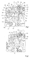
- eine Teilansicht eines Leitungsschutzschalters im Bereich des Schaltschlosses, in Ausschaltstellung und
- Fig. 2
- den Leitungsschutzschalter gemäß Fig. 1 in der gleichen zeichnerischen Darstellung, in Einschaltstellung.
- Es sei nun Bezug genommen auf die Fig. 1.
- Innerhalb eines Gehäuses 10 eines Leitungsschutzschalters 11 befindet sich ein feststehendes Kontaktstück 12, das mit einem beweglichen Kontaktstück 13 zusammenwirkt, welches an einem Kontakthebel 15 angeordnet ist, der an einem Lagerzapfen 14 drehbar gelagert ist. Der Kontakthebel 15 ist ein Doppelarmhebel mit einem ersten Kontakthebelarm 16 und einem zweiten Kontakthebelarm 17; an letzterem ist das bewegliche Kontaktstück 13 angeformt. An dem Kontakthebelarm 16 ist ein Kupplungselement 18 angelenkt, welches eine U-Form aufweist mit zwei in die Zeichenebene hinein vorspringenden Schenkeln 19 und 20. Der Schenkel 19 greift in eine Bohrung 21 am Kontakthebel an, wogegen der andere Schenkel 20 in ein Langloch 22 in einer Lasche 23 eingreift, deren anderes Ende über einen Achszapfen 24 mit einem Schaltgriff 25, der aus einer Ausnehmung 26 in der vorderen Frontwand 27 herausragt. Der Schaltknebel 25 ist um eine ortsfeste Achse 28 im Gehäuse 10 drehbar gelagert.
- Wie aus Fig. 1 hervorgeht, besitzt die Lasche 23 einen Vorsprung 29, der den Schenkel 19 überdeckt, so dass der Schenkel 19 die Lasche im eingeschalteten Zustand führt.
- An dem schaltgriffseitigen Ende der Lasche 23 befindet sich ein Laschenkopf 30, der eine dreieckförmige Umfangskontur aufweist, wobei die Umfangskontur mit einer kreisbogenförmigen Nockenfläche 31 versehen ist, deren Kreismittelpunkt mit dem Mittelpunkt der Drehachse 24 zusammen fällt. Die Mittelhalbierende des Kopfes 30 verläuft quer zur Längserstreckung der Achse 23, wobei der breitere Abschnitt des Kopfes in die Schalterinnenseite gerichtet ist; der schmalere, eine Art Spitze 32 bildende Bereich weist zu der vorderen Frontseite 27 hin.
- Am Schaltknebel 25 ist eine Feder 33 angeordnet, die als Drehfeder zwischen dem Schaltknebel 25 und der Lasche 23 wirkt und an der ein federnder Arm 24 anschließt, der mit dem Kopf 30 wie folgt zusammenwirkt:
In Ausschaltstellung, wie in der Fig. 1 dargestellt, verläuft der Schenkel oder Arm zu etwa in Richtung der Längserstreckung des Schaltgriffes 34 des Schaltknebels 25 und etwa in Längsrichtung der Mittelhalbierenden oder Symmetrielinie des Kopfes 30. Damit befindet sich der Arm 34 außerhalb der Nockenfläche 31 und drückt mit einer Kraft F1 gegen den Kopf 30 und damit gegen die Lasche 23, wobei der Kraftvektor der Kraft F1 senkrecht zum Arm 34 in einem Abstand A an der Drehachse 24 vorbeiläuft, so dass über den Abstand A, der als Hebelarm bezeichnet werden kann, die Kraft ein Drehmoment auf die Lasche 23 ausübt, die die Lasche um die Achse 24 im Uhrzeigersinn zu verschwenken trachtet. Über den Vorsprung 29 wird im Ausschaltzustand auf den Schenkel 19 eine Kraft F2 ausgeübt. - Zwischen einem ortsfesten Anschlag, hier einer vorderen Schmalseitenwand 10a und dem Kontakthebelarm 17 ist eine Druckfeder 40 angeordnet, die als Kontaktdruckfeder dient.
- Sowohl in Fig. 1 als auch in Fig. 2 ist das Kniehebelgelenkgetriebe in der ersten stabilen Lage dargestellt, wobei während des Ausschaltvorganges das Kniehebelgetriebe über eine Totpunktlage in eine zweite stabile Lage verbracht wird, aus der es durch die Federkräfte des Armes 34 wieder in die Stellung gemäß Fig. 2 verbracht wird, in der die Einschaltbewegung des Schaltgriffes über das Kniehebelgetriebe auf den Kontakthebel übertragen wird.
- Ergänzend sei noch darauf hingewiesen, dass die Drehachse 24 auf einer Linie liegt, die senkrecht zur vorderen Frontwand 27 zur nicht näher gezeichneten Befestigungsebene verläuft. Die Kraft F1 verläuft, wie angedeutet, außerhalb des Bereiches zwischen der Drehachse 28 und der Drehachse 24.
- Wenn der Schalter in Einschaltstellung zu verbringen ist, wird der Schaltgriff 34 im Uhrzeigersinn um seine Drehachse 28 verschwenkt, so dass er in die Stellung gemäß Fig. 2 gelangt. Dadurch bewegt sich der Verbindungspunkt bzw. die Drehachse oder Gelenkachse 24 entsprechend der Verschwenkung des Schaltgriffes 34 auf einer Kreisbahn um die Achse 28 in Richtung zur vorderen Frontwand hin. Der Arm 34 gleitet -bezogen auf die vordere Frontwand 27- unter die Nockenfläche 31, so dass die Kraft F1', die senkrecht zu dem Arm 31 verläuft, im Bereich der Nockenfläche 31 auf den Kopf 30 drückt, wobei die Anordnung so getroffen ist, dass der Kraftverlauf F1 nunmehr in Richtung zur vorderen Frontwand ausgerichtet ist. Dadurch verläuft die Kraft F1' durch die Drehachse 24 bzw. die Gelenkachse 24 mit der die Lasche am Schaltknebel 25 angelenkt ist. Dadurch wird die Lasche 23 drehmomentenfrei, so dass eine Kraft, die der Kraft F2 im Ausschaltzustand entspricht, nicht mehr auf den Schenkel 19 wirkt, so dass dort lediglich die Verklinkungskraft zu übertragen ist.
- Im Ausschaltzustand wirkt die Kontaktdruckfeder 40 nicht auf das Kniegelenk, da der schwenkbare Kontakthebel an einem Gehäuseanschlag 41 anliegt. Somit liegt der eine Schenkel 20 des Bügels 19 kraftfrei im Langloch 22 der Lasche 23 und hat Spiel. Ohne die Feder bzw. den Federarm 34 ist die Lage des Bügels 18 bezogen auf die Lasche 23 nicht exakt bestimmt. Im ungünstigen Falle könnte das Kniegelenk zwischen dem Bügel 18 und der Lasche 23 nach unten durchschnappen, sodass sich zwischen dem Bügel 18 und der Lasche 23 ein stumpfer Winkel bildet, der zur vorderen Frontwand geöffnet ist. Damit wäre der Kniewinkel negativ und es käme beim Einschalten zum Durchschnappen. Der Federarm 34 bewirkt nun aufgrund der Kraftwirkung der Federkraft F1 und des damit erzeugten Drehmomentes auf die Lasche 23 um den Gelenkpunkt 24 über die Lasche 23 immer nach oben in seine maximale Endstellung gedrückt wird, wodurch eine Kraftübertragung in Längsrichtung gewährleistet ist. Sie verhindert beim Einschalten ebenso wie beim Ausschalten, dass das Kniegelenk durchschnappt. Im eingeschalteten Zustand bewirkt die Kontaktdruckfeder 40 ein stabiles Kniegelenk und die Kraft F1' des Armes 34 ist nicht nötig und kann damit durch den Anlenkpunkt 24 hindurch verlaufen.
- Die Kraft F1 ist als "erste Kraft" bezeichnet und die Kraft F1' als "zweite Kraft".
- Zu ergänzen ist noch, dass die Kraft F1 senkrecht zur Längserstreckung des Schaltgriffes 34 verläuft und zwar in Richtung zum beweglichen Kontaktstück hin, entsprechend der Endstellung des Schaltknebels 25 sowohl in der Stellung gemäß Fig. 1 als auch in der Stellung gemäß Fig. 2 verläuft der Arm 34 etwa in der Längserstreckung des Schaltgriffes 34.
Claims (5)
- Leitungsschutzschalter mit einem Schaltschloss zur bleibenden Öffnung und Schließen einer Kontaktstelle (12, 13) mit einem Kontakthebel (15), an dem das bewegliche Kontaktstück (13) angeformt ist, mit einem Kniehebelgetriebe mit einer mit einem Schaltgriff (25) und einem Kupplungselement (18) verbundenen Lasche (23), wobei das Kupplungselement (18) die Lasche (23) mit dem Kontakthebel (15) verbindet, welches Kniehebelgetriebe aus einer ersten stabilen Stellung (Einschaltstellung, Fig. 2) mittels eines Auslösemechanismus über eine Totpunktstellung in eine zweite stabile Stellung verbringbar ist, wobei der Kontakthebel (15) verschwenkt und die Kontaktstelle (12, 13) bleibend geöffnet wird, dadurch gekennzeichnet, dass eine Druckfeder (33, 34) vorgesehen ist, die auf die Lasche (23) einwirkt und deren Kraft (F1) bei der Ausschaltstellung und damit zu Beginn des Einschaltvorganges etwa in Richtung der Längserstreckung der Lasche (23) und in Einschaltstellung quer dazu wirkt.
- Leitungsschutzschalter nach Anspruch 1, dadurch gekennzeichnet, dass die Druckfeder (33, 34) eine am Schaltgriff gelagerte Schraubenfeder mit einem daran angeformten, radial vorstehenden Arm (34) ist, welcher gegen die Lasche (23) federnd anliegt.
- Leitungsschutzschalter nach einem der vorherigen Ansprüche, dadurch gekennzeichnet, dass die Lasche (23) am schaltknebelseitigen Ende eine mit dem federnden Arm (34) zusammenwirkende, etwa kreisbogenförmige Nockenfläche (31) aufweist.
- Leitungsschutzschalter nach Anspruch 3, dadurch gekennzeichnet, dass die kreisbogenförmige Nockenfläche (31) an einem Kopf (30) angeformt ist, wobei sich der Arm (34) in Ausschaltstellung außerhalb der Nockenfläche (31) befindet und während des Einschaltvorganges in den Bereich der Nockenfläche (31) gleitet.
- Leitungsschutzschalter nach Anspruch 4, dadurch gekennzeichnet, dass der Kopf eine etwa dreieckförmige Form aufweist, wobei die Mittelachse des Kopfes quer zur Lasche (23) verläuft, dergestalt, dass im Ausschaltzustand der federnde Arm (34) eine erste Kraft (F1) auf die Lasche (23) und in Einschaltzustand eine zweite Kraft (F1') ausübt, welche erste Kraft ein Drehmoment auf die Lasche (23) ausübt, wodurch das Kniehebelgetriebe in Ausschaltstellung in ihre zweite stabile Lage drückt und welche zweite Kraft durch die Anlenkachse (24) der Lasche (23) am Schaltknebel (25) verläuft, wenn sich das bewegliche Kontaktstück in seiner Einschaltstellung befindet.
Applications Claiming Priority (1)
| Application Number | Priority Date | Filing Date | Title |
|---|---|---|---|
| DE102005038149A DE102005038149A1 (de) | 2005-08-12 | 2005-08-12 | Leitungsschutzschalter |
Publications (1)
| Publication Number | Publication Date |
|---|---|
| EP1753005A1 true EP1753005A1 (de) | 2007-02-14 |
Family
ID=37393860
Family Applications (1)
| Application Number | Title | Priority Date | Filing Date |
|---|---|---|---|
| EP06015648A Withdrawn EP1753005A1 (de) | 2005-08-12 | 2006-07-27 | Leitungsschutzschalter |
Country Status (5)
| Country | Link |
|---|---|
| US (1) | US7495189B2 (de) |
| EP (1) | EP1753005A1 (de) |
| CN (1) | CN1913074B (de) |
| CA (1) | CA2555927A1 (de) |
| DE (1) | DE102005038149A1 (de) |
Cited By (1)
| Publication number | Priority date | Publication date | Assignee | Title |
|---|---|---|---|---|
| CN106449314A (zh) * | 2016-09-20 | 2017-02-22 | 加西亚电子电器股份有限公司 | 一种漏电断路器 |
Families Citing this family (12)
| Publication number | Priority date | Publication date | Assignee | Title |
|---|---|---|---|---|
| TWD117319S1 (zh) * | 2005-12-21 | 2007-06-01 | 星電股份有限公司 | 電路斷路器 |
| AU312378S (en) * | 2006-06-03 | 2007-01-15 | Chint Group Corp | Miniature circuit breaker |
| CA137493S (en) * | 2010-08-31 | 2011-06-03 | Abb Stotz Kontakt Gmbh | Electrical switch |
| JP5788993B2 (ja) * | 2011-01-05 | 2015-10-07 | カーリング テクノロジーズ、 インコーポレイテッドCarling Technologies, Inc. | 超低背ロッカーのデザイン |
| CN202816829U (zh) * | 2012-09-20 | 2013-03-20 | 上海诺雅克电气有限公司 | 一种高稳定性小型断路器 |
| CA2929437C (en) * | 2013-12-27 | 2021-06-15 | Schneider Electric USA, Inc. | Two piece handle for miniature circuit breakers |
| CN105702537B (zh) * | 2016-04-14 | 2017-12-01 | 乐清市智顺电气有限公司 | 电气保护装置 |
| DE102016108292A1 (de) * | 2016-05-04 | 2017-11-09 | Abb Schweiz Ag | Elektrisches Installationsgerät mit Schaltstellungsanzeige |
| US10984974B2 (en) * | 2018-12-20 | 2021-04-20 | Schneider Electric USA, Inc. | Line side power, double break, switch neutral electronic circuit breaker |
| CN109727826B (zh) * | 2018-12-28 | 2024-08-13 | 浙江正泰电器股份有限公司 | 小型断路器 |
| CN109686626B (zh) * | 2018-12-28 | 2024-05-07 | 浙江正泰电器股份有限公司 | 小型断路器 |
| US10510506B1 (en) * | 2019-01-31 | 2019-12-17 | Carling Technologies, Inc. | Narrow profile circuit breaker with arc interruption |
Citations (3)
| Publication number | Priority date | Publication date | Assignee | Title |
|---|---|---|---|---|
| DE3516217A1 (de) * | 1984-05-15 | 1985-11-21 | Mitsubishi Denki K.K., Tokio/Tokyo | Schaltungsunterbrecher |
| EP0255483A2 (de) * | 1986-07-25 | 1988-02-03 | Weber Ag | Schaltmechanismus eines Schutzschalters |
| DE19919420A1 (de) * | 1999-04-28 | 2000-11-02 | Siemens Ag | Schutzschalteinrichtung, beispielsweise Leitungsschutzschalter |
Family Cites Families (8)
| Publication number | Priority date | Publication date | Assignee | Title |
|---|---|---|---|---|
| DE1192730B (de) * | 1962-03-09 | 1965-05-13 | Licentia Gmbh | Schaltmechanismus fuer Selbstschalter |
| NL9102154A (nl) * | 1991-12-20 | 1993-07-16 | Holec Syst & Componenten | Elektrische schakelaar, in het bijzonder een last- of vermogensschakelaar. |
| ATE164027T1 (de) * | 1993-03-17 | 1998-03-15 | Ellenberger & Poensgen | Mehrpoliger schutzschalter |
| US5753878A (en) * | 1996-04-23 | 1998-05-19 | General Electric Company | Circuit breaker having variable arc gas venting |
| DE10133878B4 (de) * | 2001-07-12 | 2004-07-08 | Siemens Ag | Schaltgerät mit einem Schaltschloss |
| US6897747B2 (en) * | 2002-05-10 | 2005-05-24 | Joseph T. Brandon | Circuit breaker |
| AU2004274983B2 (en) * | 2003-09-23 | 2009-11-12 | Moeller Gebaudeautomation Gmbh | Switch |
| ZA200506062B (en) * | 2004-10-04 | 2007-12-27 | Circuit Breaker Ind | Trip indicative rocker switch |
-
2005
- 2005-08-12 DE DE102005038149A patent/DE102005038149A1/de not_active Withdrawn
-
2006
- 2006-07-27 EP EP06015648A patent/EP1753005A1/de not_active Withdrawn
- 2006-08-10 CA CA002555927A patent/CA2555927A1/en not_active Abandoned
- 2006-08-11 US US11/502,522 patent/US7495189B2/en not_active Expired - Fee Related
- 2006-08-14 CN CN2006101149574A patent/CN1913074B/zh not_active Expired - Fee Related
Patent Citations (3)
| Publication number | Priority date | Publication date | Assignee | Title |
|---|---|---|---|---|
| DE3516217A1 (de) * | 1984-05-15 | 1985-11-21 | Mitsubishi Denki K.K., Tokio/Tokyo | Schaltungsunterbrecher |
| EP0255483A2 (de) * | 1986-07-25 | 1988-02-03 | Weber Ag | Schaltmechanismus eines Schutzschalters |
| DE19919420A1 (de) * | 1999-04-28 | 2000-11-02 | Siemens Ag | Schutzschalteinrichtung, beispielsweise Leitungsschutzschalter |
Cited By (1)
| Publication number | Priority date | Publication date | Assignee | Title |
|---|---|---|---|---|
| CN106449314A (zh) * | 2016-09-20 | 2017-02-22 | 加西亚电子电器股份有限公司 | 一种漏电断路器 |
Also Published As
| Publication number | Publication date |
|---|---|
| CN1913074B (zh) | 2010-12-22 |
| CN1913074A (zh) | 2007-02-14 |
| DE102005038149A1 (de) | 2007-02-22 |
| US20070034495A1 (en) | 2007-02-15 |
| CA2555927A1 (en) | 2007-02-12 |
| US7495189B2 (en) | 2009-02-24 |
Similar Documents
| Publication | Publication Date | Title |
|---|---|---|
| DE10152425B4 (de) | Leitungsschutzschalter | |
| DE102007015190A1 (de) | Schutzschalter | |
| WO2008052702A1 (de) | Elektrischer schalter | |
| DE102005038149A1 (de) | Leitungsschutzschalter | |
| DE3342469A1 (de) | Elektrischer schalter | |
| DE69636639T2 (de) | Lastschalter | |
| DE3516217C2 (de) | ||
| EP0184652A2 (de) | Sicherungsschalter | |
| DE102004055564B4 (de) | Elektrisches Installationsschaltgerät | |
| DE2711167A1 (de) | Schaltgestaenge fuer einen elektrischen niederspannungs-schalter | |
| DE69014741T2 (de) | Betätigungsmechanismus für elektrischen Schalter. | |
| EP1728260B1 (de) | Schaltwerk für ein elektrisches installationsschaltgerät | |
| DE3119165A1 (de) | Selbstschalter als baueinheit aus einem leitungsschutzschalter sowie hilfs- und signalschaltern | |
| DE3729688A1 (de) | Schaltungsunterbrecher | |
| EP0586733B1 (de) | Sprungantrieb für elektrische Schalter | |
| EP0091040A2 (de) | Überstromschutzschalter | |
| DE102007003403B4 (de) | Elektrischer Schalter | |
| EP0147629B1 (de) | Schutzschalter | |
| DE10218526B4 (de) | Schaltgerät | |
| EP1709660B1 (de) | Elektromechanischer schalter | |
| DE29917173U1 (de) | Betätigungseinrichtung für ein elektrisches Überstromrelais | |
| DE19507605C1 (de) | Verklinkungseinrichtung für elektrische Schalter | |
| EP1555681A1 (de) | Elektrisches Schaltgerät | |
| EP1659604B1 (de) | Installationsschaltgerät | |
| DE4339425A1 (de) | Schaltschloß für einen Fehlerstromschutzschalter |
Legal Events
| Date | Code | Title | Description |
|---|---|---|---|
| PUAI | Public reference made under article 153(3) epc to a published international application that has entered the european phase |
Free format text: ORIGINAL CODE: 0009012 |
|
| AK | Designated contracting states |
Kind code of ref document: A1 Designated state(s): AT BE BG CH CY CZ DE DK EE ES FI FR GB GR HU IE IS IT LI LT LU LV MC NL PL PT RO SE SI SK TR |
|
| AX | Request for extension of the european patent |
Extension state: AL BA HR MK YU |
|
| 17P | Request for examination filed |
Effective date: 20070404 |
|
| AKX | Designation fees paid |
Designated state(s): AT BE BG CH CY CZ DE DK EE ES FI FR GB GR HU IE IS IT LI LT LU LV MC NL PL PT RO SE SI SK TR |
|
| GRAP | Despatch of communication of intention to grant a patent |
Free format text: ORIGINAL CODE: EPIDOSNIGR1 |
|
| GRAS | Grant fee paid |
Free format text: ORIGINAL CODE: EPIDOSNIGR3 |
|
| RAP1 | Party data changed (applicant data changed or rights of an application transferred) |
Owner name: ABB AG |
|
| STAA | Information on the status of an ep patent application or granted ep patent |
Free format text: STATUS: THE APPLICATION IS DEEMED TO BE WITHDRAWN |
|
| 18D | Application deemed to be withdrawn |
Effective date: 20110201 |