EP1747839B1 - Laserbearbeitung Robotersystem - Google Patents
Laserbearbeitung Robotersystem Download PDFInfo
- Publication number
- EP1747839B1 EP1747839B1 EP06015155A EP06015155A EP1747839B1 EP 1747839 B1 EP1747839 B1 EP 1747839B1 EP 06015155 A EP06015155 A EP 06015155A EP 06015155 A EP06015155 A EP 06015155A EP 1747839 B1 EP1747839 B1 EP 1747839B1
- Authority
- EP
- European Patent Office
- Prior art keywords
- robot
- laser
- controller
- laser oscillator
- host controller
- Prior art date
- Legal status (The legal status is an assumption and is not a legal conclusion. Google has not performed a legal analysis and makes no representation as to the accuracy of the status listed.)
- Ceased
Links
Images




Classifications
-
- G—PHYSICS
- G05—CONTROLLING; REGULATING
- G05B—CONTROL OR REGULATING SYSTEMS IN GENERAL; FUNCTIONAL ELEMENTS OF SUCH SYSTEMS; MONITORING OR TESTING ARRANGEMENTS FOR SUCH SYSTEMS OR ELEMENTS
- G05B19/00—Program-control systems
- G05B19/02—Program-control systems electric
- G05B19/18—Numerical control [NC], i.e. automatically operating machines, in particular machine tools, e.g. in a manufacturing environment, so as to execute positioning, movement or co-ordinated operations by means of program data in numerical form
- G05B19/414—Structure of the control system, e.g. common controller or multiprocessor systems, interface to servo, programmable interface controller
-
- B—PERFORMING OPERATIONS; TRANSPORTING
- B23—MACHINE TOOLS; METAL-WORKING NOT OTHERWISE PROVIDED FOR
- B23K—SOLDERING OR UNSOLDERING; WELDING; CLADDING OR PLATING BY SOLDERING OR WELDING; CUTTING BY APPLYING HEAT LOCALLY, e.g. FLAME CUTTING; WORKING BY LASER BEAM
- B23K26/00—Working by laser beam, e.g. welding, cutting or boring
- B23K26/70—Auxiliary operations or equipment
- B23K26/702—Auxiliary equipment
-
- G—PHYSICS
- G05—CONTROLLING; REGULATING
- G05B—CONTROL OR REGULATING SYSTEMS IN GENERAL; FUNCTIONAL ELEMENTS OF SUCH SYSTEMS; MONITORING OR TESTING ARRANGEMENTS FOR SUCH SYSTEMS OR ELEMENTS
- G05B2219/00—Program-control systems
- G05B2219/30—Nc systems
- G05B2219/33—Director till display
- G05B2219/33162—Two bus, high speed and low speed bus, linked or not
-
- G—PHYSICS
- G05—CONTROLLING; REGULATING
- G05B—CONTROL OR REGULATING SYSTEMS IN GENERAL; FUNCTIONAL ELEMENTS OF SUCH SYSTEMS; MONITORING OR TESTING ARRANGEMENTS FOR SUCH SYSTEMS OR ELEMENTS
- G05B2219/00—Program-control systems
- G05B2219/30—Nc systems
- G05B2219/45—Nc applications
- G05B2219/45104—Lasrobot, welding robot
Definitions
- This invention relates to a robot laser processing system using an industrial robot.
- a laser processing system having an industrial robot with a processing nozzle mounted thereon, to emit a laser beam for automatically performing the desired laser processing work, is used in various areas including car assembly plants and printed circuit board production factories.
- demand is high for a configuration in which a plurality of laser oscillators different in rated output can be connected to a robot and switched in accordance with the applications and situations of a production field, or a configuration in which a second laser oscillator is connected in addition to an laser oscillator used for normal processing process and, if the oscillator for normal processing process fails for some reason, the system is switched to the second laser oscillator.
- a configuration in which a plurality of laser oscillators are connected to the robot and switched for actual use is required to meet two main conditions.
- a robot 102 controlled by a robot controller 140 includes a robot arm having a plurality of rotatably coupled arm members.
- a processing nozzle 104 mounted at the forward end of the robot 102 is connected to a laser oscillator 100-1 through an optical fiber 106.
- the laser oscillator 100-1 has four shutters 110-1, 112-1, 114-1, 116-1.
- Fig. 6 also shows another laser oscillator 100-2 which similarly has four shutters 110-2, 112-2, 114-2, 116-2.
- an operation to switch the connection of the optical fiber 106 is required first.
- the fiber 106 connected to the laser oscillator 100-1 is removed from the processing nozzle 104 of the robot 102 and the optical fiber 202 for the laser oscillator 100-2 is connected to the processing nozzle 104.
- the optical fiber 106 for the laser oscillator 100-1 may be reconnected to the laser oscillator 100-2 without removing the fiber 106 from the processing nozzle 104.
- This connecting job though carried out manually in many cases, may be conducted using an optical fiber switching device as described in Japanese Unexamined Patent Publication No. 2001-259870 .
- the laser oscillators 100-1, 100-2 use the first shutters 110-1, 110-2, respectively. In switching the oscillators, therefore, the shutter number command for the shutter which is opened when the processing operation need not be changed. In the case where the first shutter 110-1 is used for the laser oscillator 100-1 and the second shutter 112-2 is used for the laser oscillator 100-2 as shown in Fig. 8 , however, the shutter number command must be changed when switching the laser oscillators.
- the processing command from the robot After switching the optical fiber for the laser oscillator, the processing command from the robot must be transmitted to the laser oscillator after switching.
- the processing command from the robot if currently transmitted to the laser oscillator 100-1, must be transmitted to the laser oscillator 100-2 after switching from the laser oscillator 100-1 to the laser oscillator 100-2.
- Figs. 9a, 9b are block diagrams showing a general configuration of the conventional robot laser processing system.
- a host controller 120 (programmable logic controller, PLC) is directly connected with one robot controller 140 and a plurality of laser oscillators 100-1, 100-2,...., 100-n.
- the host controller 120 is connected directly with the plurality of the robot controllers 140-1, 140-2,...., 140-n and a plurality of laser oscillators 100-1, 100-2,...., 100-n.
- the laser oscillator used by the robot under the control of the robot controller 140 is not selectively switched by an instruction from the host controller (PLC, etc.).
- the laser processing command from one robot controller 140 (or 140-1) is provisionally transmitted to the host controller 120, and then to the desired laser oscillator 100-1 (or 100-2) by the host controller 120.
- this selective switching operation is performed by the host controller 120 changing the destination of the laser processing command.
- the host controller 120 similarly changes the shutter number for the desired laser oscillator.
- the host controller 120 is required to perform the control operation to switch the laser oscillator in addition to the normal line control operation and the robot control operation.
- the control operation in the host controller 120 is more complicated and leads to the problem that a considerable length of time is required to start the production line.
- the fact that the laser processing command is sent through the host controller 120 causes loss of time and lengthens the cycle time.
- the host controller 120 while controlling the factory production line in general, on the one hand, is required to meet different specifications in accordance with different line configurations, on the other hand.
- the host controller 120 executes the operation of switching the laser oscillators as described above, therefore, the problem is posed that the internal processing of the host controller 120 is complicated and a considerable length of time is required each time the production line is started.
- This invention is intended to solve these technical problems of the prior art, and the object thereof is to provide a robot laser processing system in which a processing command and a switching command can be sent directly to the laser oscillators from the robot controller without the intermediary of the host controller.
- Document US 2001/0042737 A1 discloses a laser machining apparatus which is capable of providing laser beams in a manufacturing line for motor vehicles.
- a plurality of laser beam generators are divided into groups and are aggregated to fiber-optic cables, which direct the laser beam to laser beam outlet.
- the network of fiber-optic cables is arranged in a simplified manner.
- the laser machining apparatus comprises a plurality of laser generators, one or more machining tools and machining tool moving means for supporting the machining tool.
- Each machining tool is associated with two or more of the laser generators to form a group.
- a robot laser processing system comprising at least one robot controller for controlling at least one robot, a host controller connected to the robot controller through a first network for controlling the robot controller collectively, and a plurality of laser oscillators connected to the robot controller through a second network and adapted to be selectively connected to a particular processing nozzle mounted on each robot, wherein the instruction from the host controller is transmitted to the robot controller through the first network, so that the robot controller determines the laser oscillator to be controlled and directly controls the particular laser oscillator through the second network.
- a robot laser processing system of the first aspect wherein the robot controller recognizes the laser oscillator connected to the processing nozzle of the robot to be controlled, based on the information on the laser oscillator sent from the host controller to the robot controller.
- a robot laser processing system of the first aspect wherein the instruction from the host controller constitutes an input signal to the robot controller.
- a robot laser processing system of the first aspect wherein the instruction from the host controller constitutes communication data to the robot controller.
- a robot laser processing system of the second aspect wherein the information on the laser oscillator constitutes a unique number assigned to the laser oscillator.
- the laser oscillator used for the processing control operation by the robot connected to the robot controller can be determined by the robot controller in accordance with an instruction from a host controller, such as a factory production line control unit (PLC), connected with the robot controller.
- a host controller such as a factory production line control unit (PLC)
- PLC factory production line control unit
- the processing command is issued through the direct route from the robot controller to the laser oscillator and the cycle time is shortened.
- the processing operation of the line control unit in control of the the whole factory production line is simplified and the load on the host controller is reduced, while at the same time shortening the start-up time of the production line.
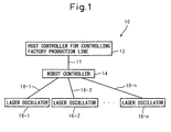
- Fig. 1 is a block diagram showing a general configuration of a robot laser processing system according to a first embodiment of the invention.
- the robot laser processing system 10 according to the first embodiment comprises a host controller 12 used for controlling a factory production line, a robot controller 14 connected to the host controller 12 through a first communication network 11, and a plurality of laser oscillators 16-1 to 16-n connected to the robot controller 14 through second communication networks 18-1 to 18-n.
- the host controller 12 can be configured of, for example, a PLC (programmable logic controller).
- Fig. 2 is a schematic diagram showing the relation between the robot, the robot controller and the laser oscillator. To facilitate understanding, Fig. 2 shows only one robot 30 and one laser oscillator 16-1. As shown in Fig. 2 , the robot 30 controlled by the robot controller 14 is assumed to be an industrial multi-joint robot including a robot arm 31 having a plurality of rotatably coupled arm members. A processing nozzle 35 for emitting a laser beam is mounted at the forward end of the robot arm. The processing nozzle 35, as explained above with reference to the prior art, is selectively connectable to one of the plurality of the laser oscillators 16-1 to 16-n through an optical fiber or, specifically in Fig. 2 , to the laser oscillator 16-1.
- the communication networks 11, 18-1 to 18-n may be formed of, for example, a signal line, a field bus, the Ethernet (registered trade mark) network based on IEEE802.3 or a serial communication network constituting a digital network used for in-factory communication between measuring and control instruments.
- the switching operation of the optical fiber to determine which one of the plurality of the laser oscillators 16-1 to 16-n is selected and connected to the processing nozzle, as described above, can be performed by manually removing the optical fiber connected to the processing nozzle and newly connecting an optical fiber to be connected to the processing nozzle or, as disclosed in Japanese Unexamined Patent Publication No. 2001- 259870 , performed automatically by an optical fiber switching device (not shown).
- the optical fiber switching device is connected to the host controller 12 by a third network not shown and controlled by the host controller 12.
- the robot controller 14 has a well-known configuration which, in addition to a shaft control amplifier used for servo control of each shaft of the robot, includes a CPU, a memory, a communication interface for conducting communication through the first communication network 11 and the second communication networks 18-1 to 18-n, input means (not shown) such as a keyboard used by the operator to operate the robot controller 14 and output means, such as a monitor, for displaying the processing conditions.
- Fig. 3 is a block diagram showing a robot controller.
- a processing program for processing a work with a laser can be stored in a memory, i.e. a storage means 41 of the robot controller 14.
- the processing program is read from the storage means 41 and then executed by a program execution means 44, so that the robot is moved along the route designated by the program.
- Fig. 4 is a diagram showing a processing program of the robot laser processing system according to the first embodiment of the invention. With reference to Fig. 4 , the operation of the first embodiment of the invention is explained below.
- the robot controller 14 When the power for the robot controller 14 is turned on (step 51), the robot controller 14 first establishes communication with the laser oscillators 16-1 to 16-n. In the process, the communication area of each of the laser oscillators 16-1 to 16-n is determined (step 52), after which the laser oscillators 16-1 to 16-n are assigned the numbers in the order of determination of the communication areas, which numbers are stored in the storage means 41 (step 53). In the case where the instruction described later from the host controller 12 contains any of the names of the laser oscillators 16-1 to 16-n, the names of the laser oscillators are also sequentially stored in the storage means 41 (step 54).
- the robot controller 14 of the robot laser processing system 10 enters a standby state waiting for an instruction from the host controller 12 (external device) (step 55).
- the instruction from the host controller 12 contains any of the unique numbers of the laser oscillators 16-1 to 16-n
- the unique numbers of the laser oscillators 16-1 to 16-n are stored in place of the names of the laser oscillators 16-1 to 16-n.
- step 56 the instruction sent from the external device, i.e. the host controller 12 through the first communication network 11 is read.
- the instruction from the host controller 12 is a signal input, for example, through an input line.
- the instruction from the host controller 12 may be communication data such as an IP address for the Ethernet (registered trade mark) or a port number for serial communication.
- the instruction from the host controller 12 contains the name of the laser oscillator, thus, the name is also read.
- the name of the laser oscillator stored in step 54 is compared with the name of the laser oscillator contained in the instruction from the host controller 12 (steps 57, 58). In the case where there exists a laser oscillator having a coincident name, the process proceeds to step 59 but, in the absence of the laser oscillator having a coincident name, the process proceeds to step 61. As described above, the unique numbers of the laser oscillators 16-1 to 16-n may alternatively be compared.
- the communication area of the laser oscillator having the name, etc. is determined by the selective switching unit 45 of the robot controller 14 as a communication area to be used in the laser processing process.
- the selective switching unit 45 selects the laser oscillator 16-2 of the laser oscillators 16-1 to 16-n (see Fig. 3 ).
- the instruction from the host controller 12 also contains the shutter number used for the laser oscillator.
- the shutter number in the instruction is also read and stored in the storage means 41 as a shutter number for use at the time of instructing laser processing.
- the process proceeds to step 61 in which the fact is indicated by alarm on a monitor or the like. After that, the process returns to step 55 to set the robot controller 14 in standby state.
- the robot controller 14 executes the processing program in accordance with the robot start/stop command sent from the host controller 12 through the first communication network 11.
- the robot is moved along the route designated by the program, while performing the on/off control and power control operation of the laser output of the selected laser oscillator through the second communication networks 18-1 to 18-n.
- the shutter number command used to open the shutter during laser processing, is sent out to the laser oscillator based on the shutter number input from the host controller 12 and used in the laser oscillator.
- the laser oscillator used by the robot connected to the robot controller for the processing control operation can be determined by the robot controller 14 in accordance with the instruction from the host controller 12. According to this invention, therefore, a processing command can be sent directly to the laser oscillator 16 from the robot controller 14 without the intermediary of the host controller 12. As can be understood from Fig. 1 , according to this invention, the processing command is transmitted directly through the route from the robot controller 14 to the laser oscillator 16. As compared with the conventional technique shown in Fig. 6 , therefore, the cycle time can be shortened. Also, as the laser processing command from the host controller 12 to the robot controller 14 is eliminated, the overall process of the host controller 12 for controlling the whole factory production line can be simplified. Thus, the load on the host controller 12 is reduced while, at the same time, making it possible to start the production line in a shorter time.
- a table describing the host controller 12 and corresponding nodes and addresses of the laser oscillators 16-1 to 16-n may be stored in the storage means of the robot controller 14 and read by the CPU to execute a communication protocol.
- the robot controller 14 confirms which one of the laser oscillators 16-1 to 16-n is connected to the processing nozzle of the robot controlled by this robot controller 14.
- the address may be the DL (data link) address in the case where the communication networks 11, 18-1 to 18-n are field buses, the IP address in the case where they are Ethernets (registered trade mark) or the port number in the case where they are serial communication networks.
- the name or unique number indicating any of the connected laser oscillators 16-1 to 16-n and the command number of the optical fiber may be input directly by the operator to the robot controller 14 through the keyboard, and read by the robot controller 14.
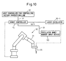
- an oscillator name/number input device 90 may be connected to the robot controller 14 through the communication network 91.
- the oscillator name/number input device 90 can be used to input the unique number of the laser oscillator and the command number of the optical fiber in addition to the name of the laser oscillator. As shown in Fig.
- the name and the unique number of the laser oscillator and the command number of the optical fiber are input by way of the oscillator name/number input device 90, and the resultant signal may be sent to the robot controller 14 through the communication network 91. Further, in the case where the switching operation of the optical fiber is carried out automatically by use of the optical fiber switching device, the name and the unique number of any one of the laser oscillators 16-1 to 16-n which is connected to the robot controller 14 and the command number of the optical fiber are sent to the robot controller 14 from the host controller 12 through the communication network 11 and may be read by the robot controller 14.
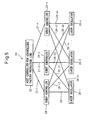
- the robot laser processing system 20 includes a host controller 22 used for controlling the factory production line, robot controllers 24-1 to 24-n connected to the host controller 22 through first communication networks 21-1 to 21-n and a plurality of laser oscillators 26-1 to 26-n connected to the robot controllers 24 through second communication networks 28-11 to 28-nn.
- each robot controlled by the robot controllers 24-1 to 24-n includes a robot arm 31 having a plurality of rotatably coupled arm members, and a processing nozzle 35 mounted at the forward end of the robot arm. Each processing nozzle is selectively connectable to only one of the plurality of the laser oscillators 26-1 to 26-n through an optical fiber without any overlap.
- the networks 21-1 to 21-n and 28-11 to 28-nn, as in the first embodiment, can be constituted of field buses, Ethernets (registered trade mark) based on IEEE802.3 or serial communication networks.
- the robot controllers 24-1 to 24-n are configured in similar manner to the robot controller 14 according to the first embodiment and will not be described in detail.
- the operation of switching the optical fiber can be performed manually by removing the optical fiber from the processing nozzle and newly connecting an optical fiber to the other processing nozzle to be connected or automatically using the optical fiber switching device (not shown) disclosed in Japanese Unexamined Patent Publication No. 2001-259870 .
- the robot controllers 24-1 to 24-n establish communication with the host controller 22 and the laser oscillators 26-1 to 26-n.
- each of the robot controllers 24-1 to 24-n compares the name, etc. contained in the instruction from the host controller 12 with the stored name, etc. and, in the case where the particular names coincide with each other, the corresponding laser oscillator is used and the shutter number is also stored.
- Each of the robot controllers 24-1 to 24-n upon confirmation of the laser oscillator to be controlled thereby in this way, executes the processing program in accordance with the robot start/stop command sent from the host controller 22 through the first communication networks 21-1 to 21-n.
- the robot is moved along the route designated by the program, on the one hand, and the on/off control and the power control of the laser output to the selected laser oscillator are performed through the second communication networks 28-11 to 28-nn, on the other hand.
- effects similar to those of the first embodiment are obtained.
Landscapes
- Engineering & Computer Science (AREA)
- Physics & Mathematics (AREA)
- Optics & Photonics (AREA)
- Plasma & Fusion (AREA)
- Mechanical Engineering (AREA)
- Human Computer Interaction (AREA)
- Manufacturing & Machinery (AREA)
- General Physics & Mathematics (AREA)
- Automation & Control Theory (AREA)
- Laser Beam Processing (AREA)
Claims (5)
- Laserbearbeitungs-Robotersystem (10) aufweisend:- mindestens eine Robotersteuereinrichtung (14, 24-1 bis 24-n) zum Steuern mindestens eines Roboters;- eine Hauptsteuereinrichtung (12, 22), die mit der Robotersteuereinrichtung (14, 24-1 bis 24-n) über ein erstes Netzwerk (11, 21-1 bis 21-n) für eine Gesamtsteuerung der mindestens einen Robotersteuereinrichtung (14, 24-1 bis 24-n) verbunden ist; und- eine Vielzahl von Laseroszillatoren (16-1 bis 16-n, 26-1 bis 26-n), die wahlweise über einen Glasfaserleiter an der Bearbeitungsdüse, die auf jedem des mindestens einen Roboters angebracht ist, verbindbar sind,dadurch gekennzeichnet,
dass die Vielzahl von Laseroszillatoren mit der Robotersteuereinrichtung (14, 24-1 bis 24-n) über ein zweites Netzwerk (18-1 bis 18-n, 28-11, 28-nn) verbunden sind;
wobei eine Anweisung von der Hauptsteuereinrichtung (12, 22) an die Robotersteuereinrichtung (14, 24-1 bis 24-n) über das erste Netzwerk (11, 21-1 bis 21-n) übermittelt wird, so dass die Robotersteuereinrichtung (14, 24-1 bis 24-n) einen anzusteuernden Laseroszillator (16-1 bis 16-n, 26-1 bis 26-n) bestimmt und den Laseroszillator (16-1 bis 16-n, 26-1 bis 26-n) unmittelbar über das zweite Netzwerk (18-1 bis 18-n, 28-11, 28-nn) ansteuert. - Laserbearbeitungs-Robotersystem (10) nach Anspruch 1, wobei die Robotersteuereinrichtung (14, 24-1 bis 24-n) aufgrund der Information über den Laseroszillator (16-1 bis 16-n, 26-1 bis 26-n), die von der Hauptsteuereinrichtung (12, 22) an die Robotersteuereinrichtung (14, 24-1 bis 24-n) gesendet wurde, den Laseroszillator (16-1 bis 16-n, 26-1 bis 26-n) erkennt, der mit der Bearbeitungsdüse des anzusteuernden Roboters verbunden ist.
- Laserbearbeitungs-Robotersystem (10) nach Anspruch 1, wobei die Anweisung von der Hauptsteuereinrichtung (12, 22) ein Eingangssignal für die Robotersteuereinrichtung (14, 24-1 bis 24-n) ist.
- Laserbearbeitungs-Robotersystem (10) nach Anspruch 1, wobei die Anweisung von der Hauptsteuereinrichtung (12, 22) Kommunikationsdaten für die Robotersteuereinrichtung (14, 24-1 bis 24-n) sind.
- Laserbearbeitungs-Robotersystem (10) nach Anspruch 2, wobei die Information über den Laseroszillator (16-1 bis 16-n, 26-1 bis 26-n) eine eindeutige Nummer ist, die dem Laseroszillator (16-1 bis 16-n, 26-1 bis 26-n) zugeordnet ist.
Applications Claiming Priority (1)
| Application Number | Priority Date | Filing Date | Title |
|---|---|---|---|
| JP2005220978A JP4302084B2 (ja) | 2005-07-29 | 2005-07-29 | ロボットレーザ加工システム |
Publications (2)
| Publication Number | Publication Date |
|---|---|
| EP1747839A1 EP1747839A1 (de) | 2007-01-31 |
| EP1747839B1 true EP1747839B1 (de) | 2010-06-02 |
Family
ID=37398289
Family Applications (1)
| Application Number | Title | Priority Date | Filing Date |
|---|---|---|---|
| EP06015155A Ceased EP1747839B1 (de) | 2005-07-29 | 2006-07-20 | Laserbearbeitung Robotersystem |
Country Status (5)
| Country | Link |
|---|---|
| US (1) | US7291806B2 (de) |
| EP (1) | EP1747839B1 (de) |
| JP (1) | JP4302084B2 (de) |
| CN (1) | CN100475413C (de) |
| DE (1) | DE602006014624D1 (de) |
Families Citing this family (8)
| Publication number | Priority date | Publication date | Assignee | Title |
|---|---|---|---|---|
| EP1690629B1 (de) * | 2005-02-09 | 2013-01-23 | Fanuc Corporation | Laserbearbeitungssystem |
| JP5336054B2 (ja) * | 2007-07-18 | 2013-11-06 | 浜松ホトニクス株式会社 | 加工情報供給装置を備える加工情報供給システム |
| JP5620553B2 (ja) * | 2013-08-01 | 2014-11-05 | 浜松ホトニクス株式会社 | 加工情報供給装置 |
| JP6975198B2 (ja) * | 2018-06-28 | 2021-12-01 | ファナック株式会社 | レーザ加工システム |
| US11154947B2 (en) | 2018-06-28 | 2021-10-26 | Fanuc Corporation | Laser processing system |
| JP7392150B2 (ja) * | 2020-06-26 | 2023-12-05 | ファナック株式会社 | レーザロボットシステム |
| WO2023042399A1 (ja) * | 2021-09-17 | 2023-03-23 | ファナック株式会社 | ロボット制御装置 |
| WO2024042729A1 (ja) * | 2022-08-26 | 2024-02-29 | ファナック株式会社 | 加工制御装置および加工制御プログラム |
Family Cites Families (6)
| Publication number | Priority date | Publication date | Assignee | Title |
|---|---|---|---|---|
| US4820899A (en) * | 1987-03-03 | 1989-04-11 | Nikon Corporation | Laser beam working system |
| JPH024052A (ja) * | 1988-06-20 | 1990-01-09 | Nissan Motor Co Ltd | 通信異常チェック方法 |
| JP3302672B2 (ja) | 2000-03-23 | 2002-07-15 | ファナック株式会社 | レーザ加工装置 |
| JP3421633B2 (ja) * | 2000-04-11 | 2003-06-30 | ファナック株式会社 | レーザ加工装置 |
| JP4479220B2 (ja) * | 2002-11-06 | 2010-06-09 | 三菱電機株式会社 | 生産設備用制御装置、生産設備制御システムおよび生産設備用制御装置による生産設備の制御方法 |
| GB0313887D0 (en) * | 2003-06-16 | 2003-07-23 | Gsi Lumonics Ltd | Monitoring and controlling of laser operation |
-
2005
- 2005-07-29 JP JP2005220978A patent/JP4302084B2/ja not_active Expired - Fee Related
-
2006
- 2006-07-20 DE DE602006014624T patent/DE602006014624D1/de active Active
- 2006-07-20 EP EP06015155A patent/EP1747839B1/de not_active Ceased
- 2006-07-27 US US11/460,498 patent/US7291806B2/en active Active
- 2006-07-28 CN CNB200610108922XA patent/CN100475413C/zh not_active Expired - Fee Related
Also Published As
| Publication number | Publication date |
|---|---|
| EP1747839A1 (de) | 2007-01-31 |
| JP2007030031A (ja) | 2007-02-08 |
| CN100475413C (zh) | 2009-04-08 |
| DE602006014624D1 (de) | 2010-07-15 |
| US7291806B2 (en) | 2007-11-06 |
| JP4302084B2 (ja) | 2009-07-22 |
| US20070023404A1 (en) | 2007-02-01 |
| CN1903496A (zh) | 2007-01-31 |
Similar Documents
| Publication | Publication Date | Title |
|---|---|---|
| EP0811451A2 (de) | Steuersystem eines Werksroboters | |
| EP1747839B1 (de) | Laserbearbeitung Robotersystem | |
| CN108818095A (zh) | 一种换刀方法及数控机床 | |
| CN113671888A (zh) | 硫化机IO-Link总线控制系统及其布局方法 | |
| CN107505917A (zh) | 伺服驱动器及伺服系统 | |
| JP2002304201A (ja) | センサ処理ユニット、コントローラ、センサおよびセンサ処理システム | |
| JP2000010615A (ja) | 制御システム | |
| EP3364260A1 (de) | Verfahren und steuerungsvorrichtung zur steuerung einer feldvorrichtung | |
| JPH0262606A (ja) | Cncの診断方式 | |
| JPH1083215A (ja) | モータ制御装置 | |
| EP3476553B1 (de) | Slave-vorrichtung, master-vorrichtung und industrielles netzwerksystem | |
| JPH07245636A (ja) | プロトコルコンバータ | |
| JPH0973310A (ja) | 数値制御装置及び数値制御システム | |
| JPH03229304A (ja) | 拡張pmc | |
| CN121239518A (zh) | 双从站的数据交换器、激光加工控制系统及方法 | |
| JP2559044B2 (ja) | プログラマブルコントローラシステム | |
| WO2026000725A1 (zh) | 一种多生产线的集成网络连接系统及数据传输方法 | |
| JP3534846B2 (ja) | 多軸位置決め制御装置 | |
| TW202603312A (zh) | 分散式風機控制系統及分散式風機控制方法 | |
| JPH03164956A (ja) | 設備管理コントローラ | |
| JPH04283B2 (de) | ||
| JP4904907B2 (ja) | スレーブ機器 | |
| JP4428260B2 (ja) | 数値制御装置及び数値制御工作機械 | |
| CN119717673A (zh) | 一种基于EtherNet/IP协议控制六轴机器人的控制方法及系统 | |
| KR20020056665A (ko) | 인쇄 회로 기판 가공 데이터 생성 시스템 및 방법 |
Legal Events
| Date | Code | Title | Description |
|---|---|---|---|
| PUAI | Public reference made under article 153(3) epc to a published international application that has entered the european phase |
Free format text: ORIGINAL CODE: 0009012 |
|
| AK | Designated contracting states |
Kind code of ref document: A1 Designated state(s): AT BE BG CH CY CZ DE DK EE ES FI FR GB GR HU IE IS IT LI LT LU LV MC NL PL PT RO SE SI SK TR |
|
| AX | Request for extension of the european patent |
Extension state: AL BA HR MK YU |
|
| 17P | Request for examination filed |
Effective date: 20070108 |
|
| 17Q | First examination report despatched |
Effective date: 20070313 |
|
| AKX | Designation fees paid |
Designated state(s): DE |
|
| GRAP | Despatch of communication of intention to grant a patent |
Free format text: ORIGINAL CODE: EPIDOSNIGR1 |
|
| GRAS | Grant fee paid |
Free format text: ORIGINAL CODE: EPIDOSNIGR3 |
|
| GRAA | (expected) grant |
Free format text: ORIGINAL CODE: 0009210 |
|
| AK | Designated contracting states |
Kind code of ref document: B1 Designated state(s): DE |
|
| REF | Corresponds to: |
Ref document number: 602006014624 Country of ref document: DE Date of ref document: 20100715 Kind code of ref document: P |
|
| RAP2 | Party data changed (patent owner data changed or rights of a patent transferred) |
Owner name: FANUC CORPORATION |
|
| PLBE | No opposition filed within time limit |
Free format text: ORIGINAL CODE: 0009261 |
|
| STAA | Information on the status of an ep patent application or granted ep patent |
Free format text: STATUS: NO OPPOSITION FILED WITHIN TIME LIMIT |
|
| 26N | No opposition filed |
Effective date: 20110303 |
|
| REG | Reference to a national code |
Ref country code: DE Ref legal event code: R097 Ref document number: 602006014624 Country of ref document: DE Effective date: 20110302 |
|
| REG | Reference to a national code |
Ref country code: DE Ref legal event code: R082 Ref document number: 602006014624 Country of ref document: DE Representative=s name: WUESTHOFF & WUESTHOFF PATENT- UND RECHTSANWAEL, DE |
|
| REG | Reference to a national code |
Ref country code: DE Ref legal event code: R082 Ref document number: 602006014624 Country of ref document: DE Representative=s name: WUESTHOFF & WUESTHOFF PATENT- UND RECHTSANWAEL, DE Effective date: 20111116 Ref country code: DE Ref legal event code: R081 Ref document number: 602006014624 Country of ref document: DE Owner name: FANUC CORPORATION, OSHINO-MURA, JP Free format text: FORMER OWNER: FANUC LTD., YAMANASHI, JP Effective date: 20111116 Ref country code: DE Ref legal event code: R082 Ref document number: 602006014624 Country of ref document: DE Representative=s name: WUESTHOFF & WUESTHOFF, PATENTANWAELTE PARTG MB, DE Effective date: 20111116 |
|
| REG | Reference to a national code |
Ref country code: DE Ref legal event code: R081 Ref document number: 602006014624 Country of ref document: DE Owner name: FANUC CORPORATION, OSHINO-MURA, JP Free format text: FORMER OWNER: FANUC CORP., YAMANASHI, JP Effective date: 20120202 Ref country code: DE Ref legal event code: R082 Ref document number: 602006014624 Country of ref document: DE Representative=s name: WUESTHOFF & WUESTHOFF PATENT- UND RECHTSANWAEL, DE Effective date: 20120202 Ref country code: DE Ref legal event code: R082 Ref document number: 602006014624 Country of ref document: DE Representative=s name: WUESTHOFF & WUESTHOFF, PATENTANWAELTE PARTG MB, DE Effective date: 20120202 |
|
| PGFP | Annual fee paid to national office [announced via postgrant information from national office to epo] |
Ref country code: DE Payment date: 20220531 Year of fee payment: 17 |
|
| REG | Reference to a national code |
Ref country code: DE Ref legal event code: R119 Ref document number: 602006014624 Country of ref document: DE |
|
| PG25 | Lapsed in a contracting state [announced via postgrant information from national office to epo] |
Ref country code: DE Free format text: LAPSE BECAUSE OF NON-PAYMENT OF DUE FEES Effective date: 20240201 |