EP1726545A2 - Bogenzuführvorrichtung und Bilderzeugungsgerät mit einer solchen darin - Google Patents
Bogenzuführvorrichtung und Bilderzeugungsgerät mit einer solchen darin Download PDFInfo
- Publication number
- EP1726545A2 EP1726545A2 EP06009875A EP06009875A EP1726545A2 EP 1726545 A2 EP1726545 A2 EP 1726545A2 EP 06009875 A EP06009875 A EP 06009875A EP 06009875 A EP06009875 A EP 06009875A EP 1726545 A2 EP1726545 A2 EP 1726545A2
- Authority
- EP
- European Patent Office
- Prior art keywords
- sheet
- stack tray
- detection sensor
- sheet stack
- drive motor
- Prior art date
- Legal status (The legal status is an assumption and is not a legal conclusion. Google has not performed a legal analysis and makes no representation as to the accuracy of the status listed.)
- Granted
Links
Images




Classifications
-
- B—PERFORMING OPERATIONS; TRANSPORTING
- B65—CONVEYING; PACKING; STORING; HANDLING THIN OR FILAMENTARY MATERIAL
- B65H—HANDLING THIN OR FILAMENTARY MATERIAL, e.g. SHEETS, WEBS, CABLES
- B65H3/00—Separating articles from piles
- B65H3/46—Supplementary devices or measures to assist separation or prevent double feed
- B65H3/52—Friction retainers acting on under or rear side of article being separated
-
- B—PERFORMING OPERATIONS; TRANSPORTING
- B65—CONVEYING; PACKING; STORING; HANDLING THIN OR FILAMENTARY MATERIAL
- B65H—HANDLING THIN OR FILAMENTARY MATERIAL, e.g. SHEETS, WEBS, CABLES
- B65H1/00—Supports or magazines for piles from which articles are to be separated
- B65H1/08—Supports or magazines for piles from which articles are to be separated with means for advancing the articles to present the articles to the separating device
- B65H1/18—Supports or magazines for piles from which articles are to be separated with means for advancing the articles to present the articles to the separating device controlled by height of pile
-
- B—PERFORMING OPERATIONS; TRANSPORTING
- B65—CONVEYING; PACKING; STORING; HANDLING THIN OR FILAMENTARY MATERIAL
- B65H—HANDLING THIN OR FILAMENTARY MATERIAL, e.g. SHEETS, WEBS, CABLES
- B65H2511/00—Dimensions; Position; Numbers; Identification; Occurrences
- B65H2511/20—Location in space
- B65H2511/22—Distance
-
- B—PERFORMING OPERATIONS; TRANSPORTING
- B65—CONVEYING; PACKING; STORING; HANDLING THIN OR FILAMENTARY MATERIAL
- B65H—HANDLING THIN OR FILAMENTARY MATERIAL, e.g. SHEETS, WEBS, CABLES
- B65H2515/00—Physical entities not provided for in groups B65H2511/00 or B65H2513/00
- B65H2515/10—Mass, e.g. mass flow rate; Weight; Inertia
-
- B—PERFORMING OPERATIONS; TRANSPORTING
- B65—CONVEYING; PACKING; STORING; HANDLING THIN OR FILAMENTARY MATERIAL
- B65H—HANDLING THIN OR FILAMENTARY MATERIAL, e.g. SHEETS, WEBS, CABLES
- B65H2555/00—Actuating means
- B65H2555/20—Actuating means angular
- B65H2555/25—D.C. motors, e.g. shunt motors
-
- B—PERFORMING OPERATIONS; TRANSPORTING
- B65—CONVEYING; PACKING; STORING; HANDLING THIN OR FILAMENTARY MATERIAL
- B65H—HANDLING THIN OR FILAMENTARY MATERIAL, e.g. SHEETS, WEBS, CABLES
- B65H2601/00—Problem to be solved or advantage achieved
- B65H2601/20—Avoiding or preventing undesirable effects
- B65H2601/22—Gravity effects, e.g. effect of weight of handled material
Definitions
- the present invention relates to a sheet feeding apparatus for feeding sheets, and an image forming apparatus equipped with the same.
- a sheet feeding apparatus connected to or equipped in an image forming apparatus such as a printer, a copying apparatus or a facsimile apparatus is generally so constructed that plural sheets stacked on a sheet stack tray are elevated to a predetermined position, and are separated and fed one by one from the uppermost one for example by a feed roller.
- a widely utilized apparatus employs a DC motor as a power source for elevating the sheet stack tray, and is equipped with height detection means for the sheet stack tray or the sheets, for detecting the height of the sheet stack tray or the uppermost sheet stacked thereon, in order to maintain the sheet stack tray at an optimum height relative to the feeding roller.
- Fig. 6 shows a number of rotations of the DC motor per unit time (hereinafter simply referred to as "rotation number") in the ordinate, as a function of a load torque of the DC motor corresponding to a sheet stacking amount in the abscissa.
- the rotation number of the DC motor increases as the sheet stacking amount on the sheet stack tray decreases.
- the sheet stack tray when the sheet stack tray is elevated and the DC motor is stopped after detecting that the uppermost sheet reaches the predetermined height, the uppermost sheet on the sheet stack tray is elevated to a position higher than the predetermined feed position. Stated differently, the sheet stack tray causes an overrun in case a small amount of sheets is stacked thereon.
- the sheet may impinge on the feed roller at the feeding operation, thereby causing a jam and hindering an appropriate sheet feeding operation.
- Japanese Patent Application Laid-open No. H03-23120 discloses a constitution in which the movement of the sheet stack tray is switched up, down, up and down at timings when the output of a detection sensor for detecting the uppermost sheet position is turned off, on, off and on.
- Japanese Patent Application Laid-open No. H03-23120 discloses a constitution in which the movement of the sheet stack tray is switched up, down, up and down at timings when the output of a detection sensor for detecting the uppermost sheet position is turned off, on, off and on.
- the present invention has been made in consideration of such situation, and an object thereof is provide a sheet feeding apparatus capable of preventing a feeding failure by an overrun of a sheet stack tray even when a small amount of sheets is stacked thereon, thereby realizing a stable feeding performance at a low cost, and an image forming apparatus equipped with such sheet feeding apparatus.
- Another object of the present invention is to provide a sheet feeding apparatus comprising a sheet stack tray movable up and down, wherein sheets to be fed are stacked on said sheet stack tray; a drive motor for moving said sheet stack tray up; a detection sensor for detecting a position of an uppermost sheet stacked on said sheet stack tray; and a control part for controlling a function of the drive motor based on a result of detection by said detection sensor, wherein, when the detection sensor detects that the uppermost sheet reaches a predetermined height while the drive motor drives to move said sheet stack tray up, said control part effects a tentative stop or a speed reduction of said drive motor and, after the tentative stop or the speed reduction, drives said drive motor to move up said sheet stacked on the sheet stack tray to a feed position.
- Fig. 2 is a cross-sectional view of an image forming apparatus equipped with a sheet feeding apparatus of the present embodiment.
- the image forming apparatus 1 is provided with a main body 10 of the image forming apparatus and a sheet cassette 2 provided in a lower part of the image forming apparatus and serving as sheet container means for stacking and storing sheets.
- the sheet cassette 2 is detachably mounted on a front side (front side relative to the plane of Fig. 2) of the image forming apparatus 1.
- the main body 10 of the image forming apparatus is provided with a pickup roller 3 which selectively advances sheets S, contained in the sheet cassette 2, from the uppermost sheet, a feed roller 4 and a retard roller 5.
- the feed roller 4 and the retard roller 5 serve to one by one separate and feed sheets advanced by the pickup roller 3.
- the main body 10 of the image forming apparatus is provided with a pair of conveying rollers 6, 7 and a pair of registration rollers 8.
- the pair of conveying rollers 6, 7 receives the sheets S fed by the feed rollers 4 and conveys them toward the pair of registration rollers 8 sequentially.
- the sheet S conveyed by the pair of conveying rollers 7 is made to impinge, at a leading end, on a nip portion of the pair of registration rollers, in a tentatively stopped state, thereby forming a loop and being corrected from skewing.
- the pair of registration rollers 8 conveys the sheet S, at a predetermined timing, to a nip portion a photosensitive drum 11 constituting image forming means incorporated a process cartridge 9 therein, and a transfer roller 12 opposed thereto.
- the process cartridge 9, incorporating known process means of the image forming apparatus 1, is detachably mounted on the main body 10 of the image forming apparatus.
- the main body 10 is also provided with a laser exposure optical system 13, which irradiates a uniformly charged surface of the photosensitive drum 11 with a laser light modulated according to image information, thereby forming an electrostatic latent image on the surface of the photosensitive drum 11.
- an unillustrated developing roller incorporated in the process cartridge 9 develops the electrostatic latent image into a toner image.
- the sheet S is conveyed by the pair of registration rollers 8 to the nip portion between the photosensitive drum 11 and the transfer roller 12, whereby the toner image formed on the photosensitive drum 11 is transferred onto the sheet S, by means of the transfer roller 12.
- the main body 10 of the image forming apparatus is provided with a fixing apparatus 14.
- the fixing apparatus 14 executes, when the sheet S bearing the transferred toner image passes, a process of heating and pressurizing the toner image thereby permanently fixing the toner image onto the sheet S.
- the sheet S, bearing the toner image fixed by the fixing apparatus 14, is conveyed by a pair of discharge rollers 15 and is discharged onto a discharge tray 16, formed on an upper surface of the image forming apparatus 1.
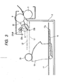
- Fig. 3 is a cross-sectional view showing the structure of the sheet feeding apparatus.
- the sheet feeding apparatus is provided with a sheet stack tray 17 for stacking sheets to be fed, drive means 20, a detection sensor 23, a control part 30 and an informing part.
- the sheet stack tray 17 is provided rotatably (vertically movably) in the sheet cassette 2.
- the sheet stack tray 17 is provided with a Through hole 17a, for receiving a lower end portion of a sheet presence/absence flag 22b to be explained later.
- the drive means 20 includes a lift arm 18, a lift gear 19, a gear 29, a lift motor 24 serving as a driving motor, a worm gear 25 and gears 26, 27, 28.
- the lift motor 24 is constituted of a DC motor.
- the lift arm 18 is fixed to the lift gear 19 at a lower part of the sheet stack tray 17.
- the lift gear 19 meshes with the gear 29, and the lift arm 18 and the lift gear 19 are rendered pivotable by the rotation of the gear 29.
- the detection sensor 23 includes a sheet height sensor 23a, and a sheet presence/absence detection sensor 23b.
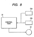
- the control part 30 constituting control means is electrically connected to the sheet height detection sensor 23a and the sheet presence/absence detection sensor 23b, constituting the detection sensor 23, and to the lift motor 24, thereby transmitting a command to the lift motor 24 based on the detection result of the detection sensor 23.
- the notifying part for example a display panel D, for example indicates that a sheet is not stacked on the sheet stack tray 17.
- Fig. 4 is a perspective view showing a gear train of the lift motor 24.
- the worm gear 25 is mounted on a driving shaft of the lift motor 24 and meshes with the gear 26, which in turn meshes with the gear 27, meshing in turn with the gear 28, whereby the revolution of the lift motor 24 is reduced.
- the lift motor 24, the worm gear 25 and the gears 26, 27, 28 are mounted in the image forming apparatus 1, and the gears 28 and 29 are connected when the sheet cassette 2 is mounted on the image forming apparatus 1.
- the detection sensor 23 constitutes parts of the sheet height detection means and the sheet presence/absence detection means.
- the sheet height detection means includes a sheet height detection sensor 23a and a sheet height detection flag 22a.
- the sheet presence/absence detection means includes a sheet presence/absence detection sensor 23b and a sheet presence/absence flag 22b. The sheet height detection means and the sheet presence/absence detection means will be explained with reference to Fig. 5.
- the feed roller 4 and the pickup roller 3 are connected by a pickup arm 22, and the pickup roller 3 is rendered pivotable about the feed roller 4.
- the pickup arm 22 is provided, at an end opposite to the feed roller 4, with the sheet height detection flag 22a, and the sheet height detection sensor 23a is turned on when the sheet height detection flag 22a intercepts the light thereto, thereby detecting the height of the sheets S stacked on the sheet stack tray 17.
- sheet presence/absence detection sensor 23b is turned on when the sheet presence/absence flag 22b transmits the light thereto, thereby detecting presence/absence of the sheet S stacked on the sheet stack tray 17.
- the sheet height detection sensor 23a and the sheet presence/absence detection sensor 23b are provided in different positions along a depth direction of the drawing.
- a sheet presence/absence detection position L1 is a contact height between a lower end portion of the sheet presence/absence flag 22b and the sheet stack tray 17 at a timing of an on/off switching of the sheet presence/absence detection sensor 23b.
- the sheet presence/absence detection sensor 23b which is a detection sensor, detects whether an uppermost sheet on the sheet stack tray 17 has reached the predetermined sheet presence/absence detection position L1.
- a sheet height detection position L2 is a contact height between the pickup roller 3 and the sheet stack tray 17 at a timing of on/off switching of the sheet height detection sensor 23a (cf. Fig. 5).
- the sheet presence/absence detection position L1 is positioned lower than the sheet height detection position L2.
- the sheet height detection position L2 corresponds to a feed position for feeding a sheet by the pickup roller 3, when the sheet is stacked on the sheet stack tray 17.
- the sheet height sensor 23a which is a height detection sensor, detects whether the uppermost sheet on the sheet stack tray 17 has reached the feed position.
- the sheet presence/absence flag 22b contacts with the upper surface of the sheet S stacked on the sheet stack tray 17, pivoting about the feed roller 4.
- the sheet stack tray 17 is provided with the through hole 17a in a position at which the end of the sheet presence/absence flag 22b contacts assuming that the sheet presence/absence flag 22b pivots in the absence of a sheet on the sheet stack tray 17.
- the sheet presence/absence flag 22b contacts the upper surface of the sheet S and pivots about the feed roller 4, thereby transmitting or intercepting the light to the sheet presence/absence detection sensor 23b and switching on/off state thereof.
- the sheet presence/absence detection position L1 is a position for judging whether the sheet presence/absence flag 22b pivots in contact with the upper surface of the sheet S.
- the sheet height detection flag 22a rotates about the feed roller 4, by a movement of the pickup roller 3 in contact with the upper surface of the sheet S on the sheet stack tray 17.
- the sheet presence/absence flag 22b contacts, earlier than the sheet height detection flag 22a, the sheet S stacked on the sheet stack tray 17. In case the sheet presence/absence flag 22b enters the Through hole 17a when the sheet stack tray 17 is moved up, because of the absence of the sheet thereon, the sheet height detection flag 22a does not move as the pickup roller 3 is not pushed up by the upper surface of the sheet S on the sheet stack tray 17.
- the sheet presence/absence flag 22b in contact with the upper surface of the sheet S pivots about the feed roller 4, the sheet presence/absence flag 22b moves at first and then the sheet height detection flag 22a moves from a position where the pickup roller 3 is in contact with the upper surface of the sheet S on the sheet stack tray 17. A position where the pickup roller 3 is in contact with the upper surface of the sheet S on the sheet stack tray 17 and pushes up the sheet height detection flag 22a becomes the feed position.
- the sheet height detection flag 22a is moved, when the upper surface of the sheet S on the sheet stack tray 17 reaches the feed position and pushes up the pickup roller 3, to execute transmission or interception of the light to the sheet height detection sensor 23a thereby causing an on/off operation thereof.
- the sheet height detection flag 22a starts to move thereby switching the on/off state of the sheet height detection sensor 23a.
- an unillustrated sheet cassette sensor detects the sheet cassette 2 (step S101). In case the sheet cassette 2 is not detected (in case the sheet cassette sensor is off), an absence of the cassette is notified (step S102).
- sheet presence/absence detection sensor 23b detects whether a sheet S is present (step S103), namely whether an uppermost sheet S is higher than the sheet presence/absence detection position L1.
- the lift motor 24 is activated to move up the sheet to a height where the sheet height detection sensor 23a is turned on (step S108).
- the sheet .. presence/absence detection sensor 23b being in an on-state at this point means that sheets S of an almost full amount are stacked on the sheet stack tray 17 and that the uppermost sheet S is located between the sheet presence/absence detection position L1 and the sheet height detection position L2.
- the rotation number of the lift motor 24 is low because of a large amount of the sheets S, so that the sheets can be stopped at an approximately optimum height even by terminating the drive of the lift motor 24 at a timing when the sheet height detection sensor 23a is turned on.
- the lift motor 24 is activated to move up the sheet stack tray 17. Then the sheet presence/absence detection sensor 23b detects whether the sheet S is present (step S104).
- the lift motor 24 is activated, and the sheet height detection sensor 23a detects the sheet height (step S105).
- the sheet height detection sensor 23a is turned on, the lift motor 24 is stopped and absence of sheet is notified (step S106).
- the sheet presence/absence flag 22b does not pivot as the lower end thereof enters the Through hole 17a of the sheet stack tray 17, so that the sheet presence/absence detection sensor 23b remains in the off-state.
- the pickup roller 3 is pushed up by the sheet stack tray 17, thereby pivoting clockwise about the feed roller 4.
- the sheet height detection flag 22a of the pickup arm 22 intercepts the light to the sheet height detection sensor 23a, which is thus turned on (cf. Fig. 7).
- the absence of sheet is notified to the user by displaying, on the display panel D shown in Fig. 1, a message that no sheet is present on the sheet stack tray 17.
- the lift motor 24 is activated.
- a period of maintaining such stopped state is selected as a period required by the rotation of the lift motor 24 to completely stop. It can be selected, for example, as a period required by the rotation of the lift motor 24 to completely stop in a state where the sheet stack amount is smallest or the sheet is not stacked.
- the sheet height detection sensor 23a detects the sheet height (step S108).
- the sheet feeding can be executed while the lift motor 24 remains stopped.
- the lift motor 24 is so activated again as to move up the sheet stack tray 17.
- control part 30 which control the lift motor 24 based on the detection results of the sheet height detection sensor 23a and the sheet presence/absence detection sensor 23b.
- the lift motor 24 is tentatively stopped at the sheet presence/absence detection position L1 which is lower than the sheet height detection position L2, and, after the tentative stop, the lift motor 24 is driven again so as to move up the sheet stack tray 17 to the position where the sheet height detection sensor 23a is turned on.
- the sheet S can be maintained at a constant height even when only a small amount of sheets S is stacked on the sheet stack tray 17, thereby enabling a stable sheet feeding.
- the lift motor 24 is tentatively stopped when the sheet presence/absence detection sensor 23b detects a sheet at the sheet presence/absence detection position L1 for detecting the uppermost sheet. It is however also possible to control the lift motor 24 so as to decelerate the sheet stack tray 17, when the sheet presence/absence detection sensor 23b detects a sheet at the sheet presence/absence detection position L1 for detecting the uppermost sheet. Then, after such deceleration of the sheet stack tray 17, it is moved up until the sheet height detection sensor 23a detects that the uppermost sheet has reached the sheet height detection position L2 which is the feed position.
Landscapes
- Engineering & Computer Science (AREA)
- Mechanical Engineering (AREA)
- Sheets, Magazines, And Separation Thereof (AREA)
- Controlling Sheets Or Webs (AREA)
Applications Claiming Priority (1)
| Application Number | Priority Date | Filing Date | Title |
|---|---|---|---|
| JP2005152755 | 2005-05-25 |
Publications (3)
| Publication Number | Publication Date |
|---|---|
| EP1726545A2 true EP1726545A2 (de) | 2006-11-29 |
| EP1726545A3 EP1726545A3 (de) | 2007-03-21 |
| EP1726545B1 EP1726545B1 (de) | 2010-02-10 |
Family
ID=36734961
Family Applications (1)
| Application Number | Title | Priority Date | Filing Date |
|---|---|---|---|
| EP06009875A Ceased EP1726545B1 (de) | 2005-05-25 | 2006-05-12 | Bogenzuführvorrichtung und Bilderzeugungsgerät mit einer solchen darin |
Country Status (7)
| Country | Link |
|---|---|
| US (1) | US7753366B2 (de) |
| EP (1) | EP1726545B1 (de) |
| JP (1) | JP2007001767A (de) |
| KR (1) | KR100804839B1 (de) |
| CN (1) | CN100524058C (de) |
| DE (1) | DE602006012136D1 (de) |
| RU (1) | RU2325698C2 (de) |
Cited By (1)
| Publication number | Priority date | Publication date | Assignee | Title |
|---|---|---|---|---|
| KR100804839B1 (ko) * | 2005-05-25 | 2008-02-20 | 캐논 가부시끼가이샤 | 시트 급송 장치 및 시트 급송 장치를 그 내부에 구비한화상 형성 장치 |
Families Citing this family (13)
| Publication number | Priority date | Publication date | Assignee | Title |
|---|---|---|---|---|
| JP4612882B2 (ja) * | 2005-09-27 | 2011-01-12 | キヤノン株式会社 | シートカセット及びシート給送装置及び画像形成装置 |
| JP2008007284A (ja) * | 2006-06-29 | 2008-01-17 | Canon Inc | シート給送装置及びその制御方法と当該シート給送装置を有する画像形成装置 |
| US20080251999A1 (en) * | 2007-04-12 | 2008-10-16 | Canon Kabushiki Kaisha | Image forming apparatus |
| JP2009078872A (ja) * | 2007-09-25 | 2009-04-16 | Kyocera Mita Corp | 給紙カセット及びそれを備えた画像形成装置 |
| JP6313535B2 (ja) * | 2012-08-27 | 2018-04-18 | ゼロックス コーポレイションXerox Corporation | 給紙装置 |
| US9199809B2 (en) * | 2013-01-18 | 2015-12-01 | Canon Kabushiki Kaisha | Sheet feeding device and image forming apparatus |
| JP2015131699A (ja) * | 2014-01-10 | 2015-07-23 | キヤノン株式会社 | シート給送装置及び画像形成装置 |
| JP6429683B2 (ja) * | 2014-03-17 | 2018-11-28 | キヤノン株式会社 | 給送装置及び画像形成装置 |
| JP6335598B2 (ja) * | 2014-04-09 | 2018-05-30 | キヤノン株式会社 | シート給送装置及び画像形成装置 |
| JP6778998B2 (ja) * | 2015-08-05 | 2020-11-04 | キヤノン株式会社 | 画像読取装置、その制御方法、及びプログラム |
| US9983536B2 (en) * | 2016-09-06 | 2018-05-29 | Kabushiki Kaisha Toshiba | Image forming system that adjusts a discharge interval from an image forming section according to a speed of a motor in a post processing section |
| JP6604302B2 (ja) * | 2016-10-18 | 2019-11-13 | 京セラドキュメントソリューションズ株式会社 | 画像形成装置 |
| KR20200011809A (ko) * | 2018-07-25 | 2020-02-04 | 휴렛-팩커드 디벨롭먼트 컴퍼니, 엘.피. | 녹업플레이트를 이동시키는 구동력에 의해 회전하는 픽업 롤러 |
Family Cites Families (52)
| Publication number | Priority date | Publication date | Assignee | Title |
|---|---|---|---|---|
| DD124786A1 (de) * | 1976-03-15 | 1977-03-16 | ||
| US4623887A (en) * | 1984-05-15 | 1986-11-18 | General Electric Company | Reconfigurable remote control |
| US4774511A (en) * | 1985-05-30 | 1988-09-27 | Nap Consumer Electronics Corp. | Universal remote control unit |
| JPS61277521A (ja) | 1985-05-31 | 1986-12-08 | Mita Ind Co Ltd | ペ−パリフトアツプ停止装置 |
| JPS63218453A (ja) * | 1987-03-05 | 1988-09-12 | Fuji Photo Film Co Ltd | 画像記録装置 |
| US6014092A (en) * | 1987-10-14 | 2000-01-11 | Universal Electronics Inc. | Key mover |
| US5481256A (en) * | 1987-10-14 | 1996-01-02 | Universal Electronics Inc. | Direct entry remote control with channel scan |
| US5515052A (en) * | 1987-10-14 | 1996-05-07 | Universal Electronics Inc. | Universal remote control with function synthesis |
| US4959810A (en) * | 1987-10-14 | 1990-09-25 | Universal Electronics, Inc. | Universal remote control device |
| JPH02123035A (ja) * | 1988-10-31 | 1990-05-10 | Toshiba Corp | 紙無し検知機構並びに画像形成装置 |
| JPH0829846B2 (ja) * | 1989-05-09 | 1996-03-27 | シャープ株式会社 | 給紙装置 |
| JPH0323120A (ja) | 1989-06-16 | 1991-01-31 | Fujitsu Ltd | 給紙面の初期停止位置制御方式 |
| JPH0467275A (ja) * | 1990-07-06 | 1992-03-03 | Matsushita Electric Ind Co Ltd | 認識方法及び認識装置 |
| JPH04277138A (ja) * | 1991-02-28 | 1992-10-02 | Ricoh Co Ltd | 給紙装置 |
| US5207416A (en) * | 1992-03-27 | 1993-05-04 | Xerox Corporation | Stack height sensing system |
| DE69435214D1 (de) * | 1993-12-10 | 2009-08-06 | Ricoh Kk | Verfahren zur Bilderkennung und zum Herausziehen und Erkennen eines spezifizierten Bildes aus einem Bildeingabesignal |
| US5472183A (en) * | 1994-03-17 | 1995-12-05 | Nisca Corporation | Sheet feeding device with multiple sheet stackers |
| US5678814A (en) * | 1994-10-20 | 1997-10-21 | Minolta Co., Ltd. | Sheet feeding apparatus having a feeding tray and paper feeding method |
| JPH08169568A (ja) * | 1994-12-21 | 1996-07-02 | Ricoh Co Ltd | 昇降式給紙トレイの制御装置 |
| JP3483356B2 (ja) | 1995-06-30 | 2004-01-06 | キヤノン株式会社 | シート給送装置および記録装置 |
| US5918873A (en) | 1995-03-30 | 1999-07-06 | Canon Kabushiki Kaisha | Sheet supplying apparatus which regulates tip end of sheet by first and second abutment means |
| US5988629A (en) * | 1996-09-30 | 1999-11-23 | Eastman Kodak Company | Control for a sheet stack supporting platform |
| US5839015A (en) * | 1996-03-28 | 1998-11-17 | Xerox Corporation | Paper height measure apparatus for a media tray with linear sensor |
| JPH10231029A (ja) | 1997-02-21 | 1998-09-02 | Canon Inc | シート供給装置及び画像形成装置 |
| KR100205595B1 (ko) * | 1997-04-24 | 1999-07-01 | 윤종용 | 급지카세트의 용지유무 감지장치 |
| US6211870B1 (en) * | 1997-07-07 | 2001-04-03 | Combi/Mote Corp. | Computer programmable remote control |
| DE19804929A1 (de) | 1998-02-07 | 1999-08-12 | Eastman Kodak Co | Vorrichtung zum Erfassen einer Blattstapelhöhe in einem Behälter |
| US6157319A (en) * | 1998-07-23 | 2000-12-05 | Universal Electronics Inc. | Universal remote control system with device activated setup |
| US7586398B2 (en) * | 1998-07-23 | 2009-09-08 | Universal Electronics, Inc. | System and method for setting up a universal remote control |
| US7218243B2 (en) * | 1998-07-23 | 2007-05-15 | Universal Electronics Inc. | System and method for automatically setting up a universal remote control |
| JP2000191152A (ja) | 1998-12-23 | 2000-07-11 | Xerox Corp | シ―ト給紙装置 |
| US6225938B1 (en) * | 1999-01-14 | 2001-05-01 | Universal Electronics Inc. | Universal remote control system with bar code setup |
| KR100524061B1 (ko) * | 1999-01-26 | 2005-10-26 | 삼성전자주식회사 | 용지 잔량 감지방법 |
| JP2000219409A (ja) | 1999-01-29 | 2000-08-08 | Canon Inc | シート処理装置及びこれを備える画像形成装置 |
| US6611622B1 (en) * | 1999-11-23 | 2003-08-26 | Microsoft Corporation | Object recognition system and process for identifying people and objects in an image of a scene |
| DE10057052B4 (de) * | 1999-12-23 | 2009-12-24 | Heidelberger Druckmaschinen Ag | Verfahren zum Steuern oder Regeln der Höhenposition von gestapelten Bogen |
| JP4321943B2 (ja) * | 2000-04-27 | 2009-08-26 | 桂川電機株式会社 | 給紙装置および給紙方法 |
| JP4536897B2 (ja) | 2000-10-02 | 2010-09-01 | キヤノン株式会社 | 画像形成装置 |
| US6763148B1 (en) * | 2000-11-13 | 2004-07-13 | Visual Key, Inc. | Image recognition methods |
| US6488277B2 (en) * | 2001-03-19 | 2002-12-03 | Hewlett-Packard Company | Sheet separation mechanism |
| US6947101B2 (en) * | 2001-08-03 | 2005-09-20 | Universal Electronics Inc. | Control device with easy lock feature |
| JP3782760B2 (ja) * | 2002-07-12 | 2006-06-07 | キヤノン株式会社 | シート給送装置及びこれを備えた画像形成装置 |
| US7029006B2 (en) | 2002-08-29 | 2006-04-18 | Canon Kabushiki Kaisha | Sheet feeding apparatus and image forming apparatus |
| KR100476977B1 (ko) * | 2002-12-09 | 2005-03-17 | 삼성전자주식회사 | 사무기기의 급지오류 감지장치 및 방법 |
| JP2005067853A (ja) * | 2003-08-27 | 2005-03-17 | Kyocera Mita Corp | 給紙装置 |
| KR100605171B1 (ko) * | 2004-04-27 | 2006-07-31 | 삼성전자주식회사 | 화상형성장치의 급지장치 및 그 제어방법 |
| US7266777B2 (en) * | 2004-09-08 | 2007-09-04 | Universal Electronics Inc. | Configurable controlling device having an associated editing program |
| US7458570B2 (en) | 2004-09-13 | 2008-12-02 | Ricoh Printing Systems, Ltd. | Sheet-supplying device |
| JP3992039B2 (ja) * | 2004-12-27 | 2007-10-17 | ブラザー工業株式会社 | シート材供給装置及び画像形成装置 |
| DE602006012136D1 (de) * | 2005-05-25 | 2010-03-25 | Canon Kk | Bogenzuführvorrichtung und Bilderzeugungsgerät mit einer solchen darin |
| JP4612882B2 (ja) | 2005-09-27 | 2011-01-12 | キヤノン株式会社 | シートカセット及びシート給送装置及び画像形成装置 |
| JP2008007284A (ja) * | 2006-06-29 | 2008-01-17 | Canon Inc | シート給送装置及びその制御方法と当該シート給送装置を有する画像形成装置 |
-
2006
- 2006-05-12 DE DE602006012136T patent/DE602006012136D1/de active Active
- 2006-05-12 EP EP06009875A patent/EP1726545B1/de not_active Ceased
- 2006-05-22 US US11/437,725 patent/US7753366B2/en active Active
- 2006-05-24 RU RU2006117886/09A patent/RU2325698C2/ru not_active IP Right Cessation
- 2006-05-24 KR KR1020060046355A patent/KR100804839B1/ko not_active Expired - Fee Related
- 2006-05-25 CN CNB2006100815224A patent/CN100524058C/zh not_active Expired - Fee Related
- 2006-05-25 JP JP2006145355A patent/JP2007001767A/ja not_active Withdrawn
Cited By (1)
| Publication number | Priority date | Publication date | Assignee | Title |
|---|---|---|---|---|
| KR100804839B1 (ko) * | 2005-05-25 | 2008-02-20 | 캐논 가부시끼가이샤 | 시트 급송 장치 및 시트 급송 장치를 그 내부에 구비한화상 형성 장치 |
Also Published As
| Publication number | Publication date |
|---|---|
| KR100804839B1 (ko) | 2008-02-20 |
| EP1726545B1 (de) | 2010-02-10 |
| DE602006012136D1 (de) | 2010-03-25 |
| CN100524058C (zh) | 2009-08-05 |
| JP2007001767A (ja) | 2007-01-11 |
| US7753366B2 (en) | 2010-07-13 |
| CN1869829A (zh) | 2006-11-29 |
| RU2325698C2 (ru) | 2008-05-27 |
| RU2006117886A (ru) | 2007-12-10 |
| KR20060121739A (ko) | 2006-11-29 |
| US20060269349A1 (en) | 2006-11-30 |
| EP1726545A3 (de) | 2007-03-21 |
Similar Documents
| Publication | Publication Date | Title |
|---|---|---|
| EP1726545B1 (de) | Bogenzuführvorrichtung und Bilderzeugungsgerät mit einer solchen darin | |
| US7308853B2 (en) | Bulk paper feeding device with intermediate conveyor for image forming device | |
| KR100325512B1 (ko) | 다수의 종이 카세트를 취급할 수 있는 종이공급방법 및 장치 | |
| EP2033915A2 (de) | Blattzuführvorrichtung und Bilderzeugungsvorrichtung damit | |
| EP2098466B1 (de) | Blattzufuhrvorrichtung und Bildlesevorrichtung | |
| US20080001342A1 (en) | Sheet feeder and image forming apparatus having said sheet feeder | |
| US7305209B2 (en) | Sheet transport device, image reading device, and image forming device | |
| US20080197563A1 (en) | Recording medium supply apparatus and image forming apparatus | |
| JP3332893B2 (ja) | シート材給送装置及び画像形成装置 | |
| JP4007277B2 (ja) | 画像形成装置 | |
| US7845631B2 (en) | Transporting device and image forming apparatus | |
| JP7508257B2 (ja) | シート給送装置及び画像形成装置 | |
| US20190300307A1 (en) | Paper feeder and image forming device incorporating same | |
| JP7627439B2 (ja) | 給送装置、及び、画像形成装置 | |
| JPH10231029A (ja) | シート供給装置及び画像形成装置 | |
| JP5943784B2 (ja) | シート給送装置及び画像形成装置 | |
| JP3815250B2 (ja) | シート供給装置 | |
| US10935916B2 (en) | Sheet conveying device and image recording apparatus | |
| JP2009078872A (ja) | 給紙カセット及びそれを備えた画像形成装置 | |
| JP2002249278A (ja) | 画像形成装置の排紙装置 | |
| JP2026061630A (ja) | シート搬送装置、画像形成装置、シート搬送方法 | |
| JP2026061631A (ja) | 画像形成装置、異常判定方法 | |
| JP2001335186A (ja) | シート残量検出装置及びシート給送装置及び画像形成装置 | |
| JPH0977271A (ja) | 画像形成装置 | |
| JP2001039553A (ja) | 画像形成装置 |
Legal Events
| Date | Code | Title | Description |
|---|---|---|---|
| PUAI | Public reference made under article 153(3) epc to a published international application that has entered the european phase |
Free format text: ORIGINAL CODE: 0009012 |
|
| AK | Designated contracting states |
Kind code of ref document: A2 Designated state(s): AT BE BG CH CY CZ DE DK EE ES FI FR GB GR HU IE IS IT LI LT LU LV MC NL PL PT RO SE SI SK TR |
|
| AX | Request for extension of the european patent |
Extension state: AL BA HR MK YU |
|
| PUAL | Search report despatched |
Free format text: ORIGINAL CODE: 0009013 |
|
| AK | Designated contracting states |
Kind code of ref document: A3 Designated state(s): AT BE BG CH CY CZ DE DK EE ES FI FR GB GR HU IE IS IT LI LT LU LV MC NL PL PT RO SE SI SK TR |
|
| AX | Request for extension of the european patent |
Extension state: AL BA HR MK YU |
|
| 17P | Request for examination filed |
Effective date: 20070921 |
|
| AKX | Designation fees paid |
Designated state(s): DE FR GB |
|
| RTI1 | Title (correction) |
Free format text: SHEET FEEDING APPARATUS AND IMAGE FORMING APPARATUS WITH SUCH A SHEET FEEDING APPARATUS THEREIN |
|
| GRAP | Despatch of communication of intention to grant a patent |
Free format text: ORIGINAL CODE: EPIDOSNIGR1 |
|
| GRAS | Grant fee paid |
Free format text: ORIGINAL CODE: EPIDOSNIGR3 |
|
| GRAA | (expected) grant |
Free format text: ORIGINAL CODE: 0009210 |
|
| AK | Designated contracting states |
Kind code of ref document: B1 Designated state(s): DE FR GB |
|
| REG | Reference to a national code |
Ref country code: GB Ref legal event code: FG4D |
|
| REF | Corresponds to: |
Ref document number: 602006012136 Country of ref document: DE Date of ref document: 20100325 Kind code of ref document: P |
|
| PLBE | No opposition filed within time limit |
Free format text: ORIGINAL CODE: 0009261 |
|
| STAA | Information on the status of an ep patent application or granted ep patent |
Free format text: STATUS: NO OPPOSITION FILED WITHIN TIME LIMIT |
|
| 26N | No opposition filed |
Effective date: 20101111 |
|
| REG | Reference to a national code |
Ref country code: FR Ref legal event code: PLFP Year of fee payment: 11 |
|
| REG | Reference to a national code |
Ref country code: FR Ref legal event code: PLFP Year of fee payment: 12 |
|
| REG | Reference to a national code |
Ref country code: FR Ref legal event code: PLFP Year of fee payment: 13 |
|
| PGFP | Annual fee paid to national office [announced via postgrant information from national office to epo] |
Ref country code: FR Payment date: 20190528 Year of fee payment: 14 |
|
| PG25 | Lapsed in a contracting state [announced via postgrant information from national office to epo] |
Ref country code: FR Free format text: LAPSE BECAUSE OF NON-PAYMENT OF DUE FEES Effective date: 20200531 |
|
| PGFP | Annual fee paid to national office [announced via postgrant information from national office to epo] |
Ref country code: GB Payment date: 20220426 Year of fee payment: 17 Ref country code: DE Payment date: 20220420 Year of fee payment: 17 |
|
| REG | Reference to a national code |
Ref country code: DE Ref legal event code: R119 Ref document number: 602006012136 Country of ref document: DE |
|
| GBPC | Gb: european patent ceased through non-payment of renewal fee |
Effective date: 20230512 |
|
| PG25 | Lapsed in a contracting state [announced via postgrant information from national office to epo] |
Ref country code: DE Free format text: LAPSE BECAUSE OF NON-PAYMENT OF DUE FEES Effective date: 20231201 Ref country code: GB Free format text: LAPSE BECAUSE OF NON-PAYMENT OF DUE FEES Effective date: 20230512 |