EP1725916B1 - Verification system for robot pose - Google Patents
Verification system for robot pose Download PDFInfo
- Publication number
- EP1725916B1 EP1725916B1 EP05703175A EP05703175A EP1725916B1 EP 1725916 B1 EP1725916 B1 EP 1725916B1 EP 05703175 A EP05703175 A EP 05703175A EP 05703175 A EP05703175 A EP 05703175A EP 1725916 B1 EP1725916 B1 EP 1725916B1
- Authority
- EP
- European Patent Office
- Prior art keywords
- sensor
- robot
- links
- sensors
- moving platform
- Prior art date
- Legal status (The legal status is an assumption and is not a legal conclusion. Google has not performed a legal analysis and makes no representation as to the accuracy of the status listed.)
- Expired - Lifetime
Links
- 238000012795 verification Methods 0.000 title claims description 8
- 238000000034 method Methods 0.000 claims description 25
- 239000012636 effector Substances 0.000 claims description 12
- 230000033001 locomotion Effects 0.000 description 11
- 238000004458 analytical method Methods 0.000 description 4
- 210000002414 leg Anatomy 0.000 description 4
- 238000001356 surgical procedure Methods 0.000 description 4
- 238000004364 calculation method Methods 0.000 description 3
- 238000006073 displacement reaction Methods 0.000 description 3
- 238000004519 manufacturing process Methods 0.000 description 2
- 241001417524 Pomacanthidae Species 0.000 description 1
- 230000009471 action Effects 0.000 description 1
- 238000001574 biopsy Methods 0.000 description 1
- 210000004556 brain Anatomy 0.000 description 1
- 230000011748 cell maturation Effects 0.000 description 1
- 230000008859 change Effects 0.000 description 1
- 238000000205 computational method Methods 0.000 description 1
- 238000013461 design Methods 0.000 description 1
- 230000000694 effects Effects 0.000 description 1
- 238000005516 engineering process Methods 0.000 description 1
- 230000002708 enhancing effect Effects 0.000 description 1
- 231100001261 hazardous Toxicity 0.000 description 1
- 238000011540 hip replacement Methods 0.000 description 1
- 238000013150 knee replacement Methods 0.000 description 1
- 238000005259 measurement Methods 0.000 description 1
- 230000007246 mechanism Effects 0.000 description 1
- 238000012986 modification Methods 0.000 description 1
- 230000004048 modification Effects 0.000 description 1
- 238000011160 research Methods 0.000 description 1
Images
Classifications
-
- G—PHYSICS
- G05—CONTROLLING; REGULATING
- G05B—CONTROL OR REGULATING SYSTEMS IN GENERAL; FUNCTIONAL ELEMENTS OF SUCH SYSTEMS; MONITORING OR TESTING ARRANGEMENTS FOR SUCH SYSTEMS OR ELEMENTS
- G05B19/00—Programme-control systems
- G05B19/02—Programme-control systems electric
- G05B19/18—Numerical control [NC], i.e. automatically operating machines, in particular machine tools, e.g. in a manufacturing environment, so as to execute positioning, movement or co-ordinated operations by means of programme data in numerical form
- G05B19/406—Numerical control [NC], i.e. automatically operating machines, in particular machine tools, e.g. in a manufacturing environment, so as to execute positioning, movement or co-ordinated operations by means of programme data in numerical form characterised by monitoring or safety
- G05B19/4062—Monitoring servoloop, e.g. overload of servomotor, loss of feedback or reference
-
- G—PHYSICS
- G05—CONTROLLING; REGULATING
- G05B—CONTROL OR REGULATING SYSTEMS IN GENERAL; FUNCTIONAL ELEMENTS OF SUCH SYSTEMS; MONITORING OR TESTING ARRANGEMENTS FOR SUCH SYSTEMS OR ELEMENTS
- G05B15/00—Systems controlled by a computer
-
- B—PERFORMING OPERATIONS; TRANSPORTING
- B25—HAND TOOLS; PORTABLE POWER-DRIVEN TOOLS; MANIPULATORS
- B25J—MANIPULATORS; CHAMBERS PROVIDED WITH MANIPULATION DEVICES
- B25J17/00—Joints
- B25J17/02—Wrist joints
- B25J17/0258—Two-dimensional joints
- B25J17/0266—Two-dimensional joints comprising more than two actuating or connecting rods
-
- B—PERFORMING OPERATIONS; TRANSPORTING
- B25—HAND TOOLS; PORTABLE POWER-DRIVEN TOOLS; MANIPULATORS
- B25J—MANIPULATORS; CHAMBERS PROVIDED WITH MANIPULATION DEVICES
- B25J9/00—Programme-controlled manipulators
- B25J9/16—Programme controls
- B25J9/1615—Programme controls characterised by special kind of manipulator, e.g. planar, scara, gantry, cantilever, space, closed chain, passive/active joints and tendon driven manipulators
- B25J9/1623—Parallel manipulator, Stewart platform, links are attached to a common base and to a common platform, plate which is moved parallel to the base
-
- G—PHYSICS
- G05—CONTROLLING; REGULATING
- G05B—CONTROL OR REGULATING SYSTEMS IN GENERAL; FUNCTIONAL ELEMENTS OF SUCH SYSTEMS; MONITORING OR TESTING ARRANGEMENTS FOR SUCH SYSTEMS OR ELEMENTS
- G05B2219/00—Program-control systems
- G05B2219/30—Nc systems
- G05B2219/42—Servomotor, servo controller kind till VSS
- G05B2219/42318—Using two, more, redundant measurements or scales to detect bad function
-
- G—PHYSICS
- G05—CONTROLLING; REGULATING
- G05B—CONTROL OR REGULATING SYSTEMS IN GENERAL; FUNCTIONAL ELEMENTS OF SUCH SYSTEMS; MONITORING OR TESTING ARRANGEMENTS FOR SUCH SYSTEMS OR ELEMENTS
- G05B2219/00—Program-control systems
- G05B2219/30—Nc systems
- G05B2219/50—Machine tool, machine tool null till machine tool work handling
- G05B2219/50162—Stewart platform, hexapod construction
Definitions
- the present invention relates to the field of verifying the reliability of the controlled end effector pose in robots, especially with regard to the minimal back-up configuration required to assure a statistically acceptable level of reliability of the robot pose.
- Robotic systems have been recently entered the medical arena for enhancing the surgeons' ability to precisely and minimally invasively position surgical tools.
- they have been used for remote manipulation (e.g. the daVinci ® system supplied by Intuitive Surgical Inc., of Sunnyvale, CA), as semi active devices for brain biopsies applications (the NeuroMateTM system, supplied by Integrated Surgical Systems Inc., of Davis, CA) and as an active robot for hip and knee replacement (e.g. the ROBODOC ® system, supplied by Integrated Surgical Systems Inc., of Davis, CA).
- each joint actuator affects the end-effector location serially and there is generally no internal position sensor that measures the end-effector location.
- each encoder needs to be backed up by a second encoder on the same axis.
- the present invention seeks to provide a method of verifying the positional reliability of a robot, by utilizing only a single extra sensor attached between the end actuator and the base.
- the use of such a single extra sensor provides effective back up that may be considered statistically significant for common applications, for any sensor/encoder failure occurring anywhere in the system, whether in one of the sensors associated with the actuating links or hinges of the robot, or in the extra sensor itself.
- a single additional sensor effectively provides the robotic system with one redundant information input to the robot control algorithm, which can be used in order to determine whether any of the other control sensors, or even the additional sensor itself, has failed and is delivering an erroneous reading, and hence to warn the operator of the failure. Furthermore, the use of a single additional sensor is able to provide useful warning of the simultaneous failure of two sensors or more, given that the likelihood that two sensors or more fail simultaneously in a mode that makes the failures undetectable, is so small that it can be regarded as statistically insignificant, and hence, within the safety requirements of such robots, even for use in surgical procedures.
- the method and apparatus of the present invention may be applied for use in robots having any number of degrees of freedom, and the additional sensor generally provides one redundant measurement over and above that provided by the number of sensors necessary for the degrees of freedom of the particular robot.
- the sensors utilized in the present invention whether for determining the status of the actuating links or hinges of the robot, or whether the additional sensor itself, may be either length sensors, or angular sensors, or a combination thereof. If a length sensor, then the status of the actuator link determined is its length; if an angular sensor, then the status determined is the angular orientation of the associated link or hinge.
- the terms encoder and sensor are often used interchangeably, even though more formally, the sensor is any device used to ascertain a link length or a joint angle, and an encoder is a device for providing a digital output signal according to the length or angle detected by the device.
- the sensor is any device used to ascertain a link length or a joint angle
- an encoder is a device for providing a digital output signal according to the length or angle detected by the device.
- At least one of the adjustable links may preferably be a linear extensible link, in which case the sensor associated with the linear extensible link is a length sensor.
- at least one of the adjustable links may be an angular rotational hinge, in which case the sensor associated therewith is an angular sensor.
- the single additional sensor may preferably be either a length sensor or an angular sensor.
- the controller preferably provides an absolute verification of at least one of the position and orientation of the moving platform in the event that any one sensor is providing an erroneous output.
- the controller may provide a verification having a statistically insignificant probability of falsehood, of at least one of the position and orientation of the moving platform, in the event that two or more sensors simultaneously provide erroneous outputs.
- the maximum value of that statistically insignificant probability is the product of the square of the probability that one sensor is providing an erroneous output divided by the number of incremental positions in that one of the sensors having the least resolution '
- the plurality of extensible links may preferably be six links, and the single additional sensor a seventh sensor, or the plurality of links may preferably be four links, and the single additional sensor a fifth sensor, or even more generally, the single additional sensor is one sensor more than the number of degrees of freedom of the robot.
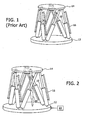
- Fig. 1 illustrates schematically a prior art exemplary parallel robot, with six extensible links 10.
- Each of the six extensible links is connected between the base platform 12 and the moving end-effector platform 14, preferably by means of a spherical joint at one end of the link and a U-joint at the other.
- each link length is measured by means of a position or length sensor 16 that moves with the link, and which provides a feedback signal to the robot control system indicating the length of the link, and hence, in combination with the information from the other link sensors, the position and orientation (pose) of the moving platform 14.
- the prior art methods of ensuring the reliability of the robot position are either to double-up each sensor 16 with a back-up sensor fixed adjacent to the primary sensor on each link, the sole purpose being to provide a one-to-one back-up for each sensor, or, according to the methods described in the above mentioned International Publication No. WO 01/19272 , to add three or more sensors connected between the base platform 12 and the moving platform 14. Either of these solutions is expensive in terms of available space and cost.
- Fig. 2 illustrates schematically the parallel robot shown in Fig. 1 , but adapted according to a preferred embodiment of the present invention, by the addition of one extra sensor, the 7 th sensor, 20, attached between the moving and the base platform, preferably in their central regions, such that it measures the distance between the attachment points on the moving and the base platforms.
- This extra sensor enables absolute verification of the moving platform location if one sensor fails, and statistically reliable verification of the moving platform if two or more sensors fail.
- Changing the lengths of the extensible links generally changes the distance between the platform centers, and this change is detected by the 7 th sensor.
- the data from this 7 th sensor is passed, preferably through a connector in the base to the robot control system 22, together with all of the encoder outputs from the six extensible links, and the data is compared for compatibility. Since the moving platform to which the 7 th sensor is connected is a rigid body, the length of the 7 th sensor is uniquely determined by the known length of the six links and hence provides backup information in the case of incorrect platform position. If as a result of a sensor failure, the moving platform is sent to a position other than that defined by the six sensor readings, then the 7 th sensor will provide an inconsistent readout, and the controller 22 thus provides warning of a sensor failure.
- a length sensor is a particularly convenient configuration for the 7 th sensor, and such a length sensor is used to illustrate the various preferred embodiments of the present invention, it is to be understood that the invention is not meant to be limited to use of a length sensor as the additional sensor, and that it is also implementable using an angular sensor as the additional sensor.
- the moving platform might perform a pure rotation about its diametric axis, which will not be detected by the 7 th sensor, if the 7 th sensor is a length sensor, but may be detected if the seventh sensor is an angular sensor, depending on the type of angular sensor.
- the moving platform trajectories that maintain the 7 th sensor reading constant should be calculated.
- Such singular configurations arise either when the robot cannot physically get to a commanded point, in which case the robot is said to have lost one degree of freedom, or when the robot loses control of the moving platform, which can undergo a displacement even while all the actuators maintain their length, in which case the robot is said to have gained one extra degree of freedom.
- Most practically used robots, including the 6-link parallel robot used to describe this preferred embodiment of the present invention are designed in such a way that all of the possible singular configurations are outside of the robot work envelope.
- any unplanned platform motion generated by an erroneous link-length sensor is positively detected by the 7th sensor. This is true since otherwise, there would be two different distinct solutions for the link lengths for the same position and orientation of the moving platform, as determined up to a single assembly mode by the inverse kinematics from the 5 link-length sensors and the 7 th sensor.
- the robot can switch assembly modes only when it passes through a singular configuration, which has been defined above as being out of the working envelope.
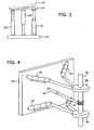
- Fig. 3 shows two links 30, 32, and the 7 th sensor 34 of a six-link parallel robot of the type shown in the embodiment of Fig. 2 .
- the "correct" position of the moving platform 14 is shown as a full line. Due to the incorrect output reading of the sensor of the right hand link 30, the control system is provided with a signal from this sensor that makes the control system believe that the moving platform is in the tilted position 14', as indicated by the dotted lines, while the 7 th sensor 34 outputs correctly that its length has not changed, as the moving platform has performed a tilt about the point of attachment of the 7 th sensor.
- the location of the moving platform is defined by only 5 distance readings (4 link-lengths and the 7 th sensor), then it is not fully defined and the platform might move freely and have an infinite number of locations. Now whatever the reading of one failed sensor, it incorrectly defines the position of the moving platform, since the situation is effectively the same as the previous case with only one failed sensor. Whatever the first failing sensor reading is, there are now six other readings, the five correctly reading sensors and the seventh one. This uniquely determines the location of the platform (up to assembly mode) and hence we are at the same point as the analysis of one sensor failing, and can continue from that point by noting that for one sensor failing there is no way it can go undetected. This means that there is only one combination within the current assembly mode, of the two failed sensors that match the remaining five correctly operating sensors.
- the probability that the platform undergoes a movement without being detected by the 7 th sensor when either one or two sensors fail simultaneously may be calculated by the following procedure:
- the probability for a single sensor error reading during a one hour surgical procedure might be reduced by as much as an order of magnitude, to 10 -3 .
- the probability of such an undetected failure in a single operation is 2.44 x 10 -10 . This is equivalent to the probability that if the robot is used for performing such a one hour surgical procedure on every one of the earth's current population, then using the 7 th sensor back-up system of the present invention, only one undetected failure arising from a double sensor failure will be statistically expected.
- the probability that three or more sensors fail without being detected by the use of the 7 th sensor is, of course, even smaller than the probability that two sensors fail without this being detected.
- Fig. 4 illustrates schematically the application of the methods of the present invention to a further preferred type of parallel robot, similar to that described in U.S. Patent No. 6,837,892 for "Miniature Bone-mounted Surgical Robot" to the inventor of the present application.
- the parallel robot shown in Fig. 4 has a base member 40, to which are flexibly connected four extensible links 42, each with their own length sensor installed, and which provide controlled motion to the end effector, which is preferably shown in Fig. 4 as a guide tube 44 supported by two ring joints 46 whose position is moved by extension of the links 42. A tool can be inserted through the guide tube 44 and maneuvered to the desired position.
- a fifth sensor 48 is attached between a known point on the base member 40 and a known point on the end effector 46, and the output of this 5 th sensor is utilized, in the same way as is described hereinabove with respect to the 7 th sensor in the six-link robot of Fig. 2 , to provide back-up information to verify the position of the end effector provided by the four extensible link sensors.
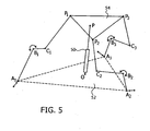
- FIG. 5 is a perspective view of the kinematic configuration of a further robot type, having a hybrid series-parallel configuration.
- Fig. 5 illustrates schematically the application of the methods of the present invention to such a hybrid robot configuration.
- the robot is similar in mechanical structure to that described in the article entitled " Kinematic Structure of a Parallel Robot for MEMS Fabrication" by H.
- the preferred robot configuration shown in Fig. 5 differs from the first above-mentioned robot in that, besides the three linear motors located at the base of the robot, it also comprises an angular actuator in each of its jointed arms, such that the moving platform is endowed with a total of six degrees of freedom.
- the fixed robot base 52 is connected to the moving platform 54, by means of three articulated legs.
- Each leg preferably has three arms, each arm including one linear motor and one rotational motor.
- leg A1, B1, C1, P1 is attached to the base at point A1, which is moved in the plane of the base by means of a linear motor, has an angular rotational motor, preferably at revolute hinge B1, a passive revolute hinge at C1, and is connected to the moving platform 54 at point P1.
- Such a robotic structure is not a pure parallel configuration, because of the action of the additional links and joints connected in each loop, whose effect is serial to the motion imparted to each leg by the linear motors at the base.
- the robot shown in Fig. 5 includes an additional redundant sensor 50, connected between a point O in the central region of the base, and a point P on the central region of the moving platform.
- This 7 th sensor is operative to provide verification information about the expected moving platform position. Failure of one or more motor encoders/sensors, whether linear or rotational, will be detected by the additional redundant sensor, in a similar manner to that described above for the pure parallel robot configurations.
- the robotic configuration shown in Fig. 5 is only one preferred embodiment of a hybrid robot to which the methods of the present invention can be successfully applied, and other hybrid robot configurations can also use a single redundant sensor to detect sensor failure.
- One common preferred configuration of such a different type could have a linear motor as the serial actuator within the link, rather than the angular actuator in the preferred embodiment shown in Fig. 5 .
Landscapes
- Engineering & Computer Science (AREA)
- Mechanical Engineering (AREA)
- Robotics (AREA)
- General Physics & Mathematics (AREA)
- Automation & Control Theory (AREA)
- Physics & Mathematics (AREA)
- Health & Medical Sciences (AREA)
- General Health & Medical Sciences (AREA)
- Orthopedic Medicine & Surgery (AREA)
- Human Computer Interaction (AREA)
- Manufacturing & Machinery (AREA)
- General Engineering & Computer Science (AREA)
- Manipulator (AREA)
- Transmission And Conversion Of Sensor Element Output (AREA)
Applications Claiming Priority (2)
| Application Number | Priority Date | Filing Date | Title |
|---|---|---|---|
| US54125604P | 2004-02-04 | 2004-02-04 | |
| PCT/IL2005/000132 WO2005074368A2 (en) | 2004-02-04 | 2005-02-03 | Verification system for robot pose |
Publications (3)
| Publication Number | Publication Date |
|---|---|
| EP1725916A2 EP1725916A2 (en) | 2006-11-29 |
| EP1725916A4 EP1725916A4 (en) | 2008-08-13 |
| EP1725916B1 true EP1725916B1 (en) | 2012-11-21 |
Family
ID=34837471
Family Applications (1)
| Application Number | Title | Priority Date | Filing Date |
|---|---|---|---|
| EP05703175A Expired - Lifetime EP1725916B1 (en) | 2004-02-04 | 2005-02-03 | Verification system for robot pose |
Country Status (7)
| Country | Link |
|---|---|
| US (1) | US8442677B2 (enExample) |
| EP (1) | EP1725916B1 (enExample) |
| JP (1) | JP4833084B2 (enExample) |
| KR (1) | KR101151515B1 (enExample) |
| AU (1) | AU2005211244B2 (enExample) |
| CA (1) | CA2555334C (enExample) |
| WO (1) | WO2005074368A2 (enExample) |
Families Citing this family (46)
| Publication number | Priority date | Publication date | Assignee | Title |
|---|---|---|---|---|
| US8768516B2 (en) * | 2009-06-30 | 2014-07-01 | Intuitive Surgical Operations, Inc. | Control of medical robotic system manipulator about kinematic singularities |
| ATE491551T1 (de) * | 2004-06-10 | 2011-01-15 | Abb Ab | Kinematischer parallelroboter und verfahren zur steuerung dieses roboters |
| CZ303752B6 (cs) * | 2006-01-04 | 2013-04-24 | CVUT v Praze - fakulta strojní | Zpusob a zarízení pro merení a/nebo kalibraci polohy telesa v prostoru |
| US8219178B2 (en) * | 2007-02-16 | 2012-07-10 | Catholic Healthcare West | Method and system for performing invasive medical procedures using a surgical robot |
| US8219177B2 (en) * | 2006-02-16 | 2012-07-10 | Catholic Healthcare West | Method and system for performing invasive medical procedures using a surgical robot |
| EP1991121B1 (en) * | 2006-02-16 | 2014-08-06 | Globus Medical, Inc. | System utilizing radio frequency signals for tracking and improving navigation of slender instruments during insertion into the body |
| JP4960038B2 (ja) * | 2006-08-09 | 2012-06-27 | オークマ株式会社 | パラレルメカニズム機械の制御方法及び制御装置 |
| JP4280278B2 (ja) * | 2006-09-29 | 2009-06-17 | ファナック株式会社 | エンコーダ通信回路 |
| US8683429B2 (en) * | 2008-08-25 | 2014-03-25 | Adobe Systems Incorporated | Systems and methods for runtime control of hierarchical objects |
| US8373704B1 (en) | 2008-08-25 | 2013-02-12 | Adobe Systems Incorporated | Systems and methods for facilitating object movement using object component relationship markers |
| JP5471482B2 (ja) * | 2010-01-18 | 2014-04-16 | トヨタ自動車株式会社 | パラレルリンク型ロボット及びその異常検知方法 |
| JP5054842B2 (ja) * | 2010-03-17 | 2012-10-24 | パナソニック株式会社 | パラレルリンクロボット、および、パラレルリンクロボットの教示方法 |
| JP5476195B2 (ja) * | 2010-04-09 | 2014-04-23 | 株式会社トライフォース・マネジメント | 力検出機能をもった駆動装置 |
| CA2713053A1 (en) * | 2010-08-12 | 2012-02-12 | Socpra-Sciences Et Genie S.E.C. | Device for orienting an object according to a given spatial orientation |
| US9707043B2 (en) | 2011-09-02 | 2017-07-18 | Stryker Corporation | Surgical instrument including housing, a cutting accessory that extends from the housing and actuators that establish the position of the cutting accessory relative to the housing |
| US9044863B2 (en) | 2013-02-06 | 2015-06-02 | Steelcase Inc. | Polarized enhanced confidentiality in mobile camera applications |
| FR3010628B1 (fr) | 2013-09-18 | 2015-10-16 | Medicrea International | Procede permettant de realiser la courbure ideale d'une tige d'un materiel d'osteosynthese vertebrale destinee a etayer la colonne vertebrale d'un patient |
| FR3012030B1 (fr) | 2013-10-18 | 2015-12-25 | Medicrea International | Procede permettant de realiser la courbure ideale d'une tige d'un materiel d'osteosynthese vertebrale destinee a etayer la colonne vertebrale d'un patient |
| KR101606075B1 (ko) | 2014-06-30 | 2016-03-25 | 주식회사 고영테크놀러지 | 병렬형 마이크로 로봇 및 이를 갖는 수술 로봇 시스템 |
| WO2017073055A1 (ja) * | 2015-10-27 | 2017-05-04 | パナソニックIpマネジメント株式会社 | 搬送装置 |
| AU2016349705B2 (en) | 2015-11-04 | 2021-07-29 | Medicrea International | Methods and Apparatus for spinal reconstructive surgery and measuring spinal length and intervertebral spacing, tension and rotation |
| JP6565752B2 (ja) * | 2016-03-17 | 2019-08-28 | 株式会社安川電機 | ロボット制御装置及びロボット制御方法 |
| US10315311B2 (en) | 2016-03-22 | 2019-06-11 | The Boeing Company | Robots, robotic systems, and related methods |
| JP2017177290A (ja) * | 2016-03-30 | 2017-10-05 | ソニー株式会社 | アーム制御方法及びアーム制御装置 |
| US11209121B2 (en) | 2016-04-26 | 2021-12-28 | The Boeing Company | Lifting support device and method of controlling operation |
| US10065311B1 (en) * | 2016-06-08 | 2018-09-04 | X Development Llc | Singularity handling for robot jogging |
| WO2018109556A1 (en) | 2016-12-12 | 2018-06-21 | Medicrea International | Systems and methods for patient-specific spinal implants |
| AU2018253996A1 (en) | 2017-04-21 | 2019-10-17 | Medicrea International | A system for developing one or more patient-specific spinal implants |
| US11033341B2 (en) | 2017-05-10 | 2021-06-15 | Mako Surgical Corp. | Robotic spine surgery system and methods |
| US11065069B2 (en) | 2017-05-10 | 2021-07-20 | Mako Surgical Corp. | Robotic spine surgery system and methods |
| US11221497B2 (en) | 2017-06-05 | 2022-01-11 | Steelcase Inc. | Multiple-polarization cloaking |
| US10918422B2 (en) | 2017-12-01 | 2021-02-16 | Medicrea International | Method and apparatus for inhibiting proximal junctional failure |
| US10762727B2 (en) * | 2017-12-29 | 2020-09-01 | Loon Llc | Estimation of aerial vehicle state |
| US11106124B2 (en) | 2018-02-27 | 2021-08-31 | Steelcase Inc. | Multiple-polarization cloaking for projected and writing surface view screens |
| US10888385B2 (en) | 2018-07-09 | 2021-01-12 | Point Robotics Medtech Inc. | Calibration device and calibration method for surgical instrument |
| CN108858273A (zh) * | 2018-07-17 | 2018-11-23 | 东北大学 | 一种气动肌肉驱动的六自由度柔顺关节 |
| DE102018126022B3 (de) * | 2018-10-19 | 2019-12-12 | Physik Instrumente (Pi) Gmbh & Co. Kg | Anordnung zur Positionierung und Positionserfassung einer verformbaren Lasttragplatte |
| US11925417B2 (en) | 2019-04-02 | 2024-03-12 | Medicrea International | Systems, methods, and devices for developing patient-specific spinal implants, treatments, operations, and/or procedures |
| US11877801B2 (en) | 2019-04-02 | 2024-01-23 | Medicrea International | Systems, methods, and devices for developing patient-specific spinal implants, treatments, operations, and/or procedures |
| US11944385B2 (en) | 2019-04-02 | 2024-04-02 | Medicrea International | Systems and methods for medical image analysis |
| CN114375183A (zh) | 2019-07-15 | 2022-04-19 | 史赛克公司 | 机器人手持式外科器械系统和方法 |
| CN110722540B (zh) * | 2019-10-31 | 2021-04-06 | 北京机械设备研究所 | 一种气动人工肌肉驱动的三自由度平台 |
| US11769251B2 (en) | 2019-12-26 | 2023-09-26 | Medicrea International | Systems and methods for medical image analysis |
| DE102020106741A1 (de) | 2020-03-12 | 2021-09-16 | Physik Instrumente (PI) GmbH & Co KG | 6-Achs-Positioniersystem mit arretierender Komponente |
| KR102471779B1 (ko) * | 2021-06-03 | 2022-11-28 | 원광대학교산학협력단 | 마이크로 나노 로봇 제어 시스템 |
| KR102734486B1 (ko) * | 2022-10-31 | 2024-11-25 | 원광대학교산학협력단 | 코일 틸팅 기반의 마이크로 나노 로봇 제어 시스템 |
Family Cites Families (26)
| Publication number | Priority date | Publication date | Assignee | Title |
|---|---|---|---|---|
| FR2549916B1 (fr) * | 1983-07-25 | 1988-05-20 | Onera (Off Nat Aerospatiale) | Dispositif d'articulation actif a compliance |
| US5382885A (en) * | 1993-08-09 | 1995-01-17 | The University Of British Columbia | Motion scaling tele-operating system with force feedback suitable for microsurgery |
| JP3640087B2 (ja) * | 1994-11-29 | 2005-04-20 | 豊田工機株式会社 | 工作機械 |
| US5847528A (en) * | 1995-05-19 | 1998-12-08 | Canadian Space Agency | Mechanism for control of position and orientation in three dimensions |
| JPH0966480A (ja) * | 1995-08-29 | 1997-03-11 | Toyoda Mach Works Ltd | 工具ハンドおよびそれを用いた工作機械 |
| DE19534535C2 (de) * | 1995-09-18 | 2000-05-31 | Leitz Mestechnik Gmbh | Koordinatenmeßmaschine |
| US5987726A (en) | 1996-03-11 | 1999-11-23 | Fanuc Robotics North America, Inc. | Programmable positioner for the stress-free assembly of components |
| FR2754205A1 (fr) | 1996-10-07 | 1998-04-10 | Gec Alsthom Syst Et Serv | Robot a structure parallele |
| US5870834A (en) * | 1996-10-22 | 1999-02-16 | Sheldon/Van Someren, Inc. | Six-axis metrology sensor device |
| US6047610A (en) * | 1997-04-18 | 2000-04-11 | Stocco; Leo J | Hybrid serial/parallel manipulator |
| JPH1110575A (ja) | 1997-06-26 | 1999-01-19 | Toshiba Mach Co Ltd | パラレルリンク機構 |
| JP3807847B2 (ja) * | 1997-08-11 | 2006-08-09 | 株式会社ジェイテクト | 工作機械の制御方法 |
| JPH11274031A (ja) * | 1998-03-20 | 1999-10-08 | Canon Inc | 露光装置およびデバイス製造方法ならびに位置決め装置 |
| US6021579A (en) * | 1998-04-01 | 2000-02-08 | Joseph M. Schimmels | Spatial parallel compliant mechanism |
| SE513503C2 (sv) * | 1998-08-26 | 2000-09-25 | Alfa Laval Agri Ab | Förfarande och anordning för att styra rörelsen hos en robotarm hos en mjölkningsrobot |
| US6497548B1 (en) * | 1999-08-05 | 2002-12-24 | Shambhu Nath Roy | Parallel kinematics mechanism with a concentric sperical joint |
| DE19944457C1 (de) | 1999-09-16 | 2001-05-17 | Urs Universal Robot Systems Gm | Präzisionsroboter mit paralleler Kinematik |
| JP4290312B2 (ja) * | 2000-03-30 | 2009-07-01 | 三菱プレシジョン株式会社 | パラレル機構と、その制御方法及び制御装置 |
| US6418811B1 (en) * | 2000-05-26 | 2002-07-16 | Ross-Hime Designs, Inc. | Robotic manipulator |
| WO2001098023A1 (fr) * | 2000-06-23 | 2001-12-27 | Constructions Mecaniques Des Vosges-Marioni | Procede pour determiner la position relative des deux plateaux d'un hexapode |
| US6837892B2 (en) * | 2000-07-24 | 2005-01-04 | Mazor Surgical Technologies Ltd. | Miniature bone-mounted surgical robot |
| US6729202B2 (en) * | 2001-05-31 | 2004-05-04 | UNIVERSITé LAVAL | Cartesian parallel manipulators |
| US7040033B2 (en) * | 2001-10-05 | 2006-05-09 | Trustees Of Stevens Institute Of Technology | Six degrees of freedom precision measuring system |
| CN1233511C (zh) * | 2002-05-23 | 2005-12-28 | 河北工业大学 | 可重组模块化3~6自由度结构解耦并联微动机器人 |
| WO2003102495A2 (en) * | 2002-06-04 | 2003-12-11 | Zygo Corporation | Metrology system for precision 3d motion |
| US7039498B2 (en) * | 2003-07-23 | 2006-05-02 | Newport Corporation | Robot end effector position error correction using auto-teach methodology |
-
2005
- 2005-02-03 KR KR1020067016898A patent/KR101151515B1/ko not_active Expired - Fee Related
- 2005-02-03 CA CA2555334A patent/CA2555334C/en not_active Expired - Fee Related
- 2005-02-03 JP JP2006552006A patent/JP4833084B2/ja not_active Expired - Fee Related
- 2005-02-03 US US10/597,673 patent/US8442677B2/en active Active
- 2005-02-03 WO PCT/IL2005/000132 patent/WO2005074368A2/en not_active Ceased
- 2005-02-03 AU AU2005211244A patent/AU2005211244B2/en not_active Ceased
- 2005-02-03 EP EP05703175A patent/EP1725916B1/en not_active Expired - Lifetime
Also Published As
| Publication number | Publication date |
|---|---|
| EP1725916A2 (en) | 2006-11-29 |
| AU2005211244A2 (en) | 2005-08-18 |
| KR101151515B1 (ko) | 2012-07-06 |
| US8442677B2 (en) | 2013-05-14 |
| EP1725916A4 (en) | 2008-08-13 |
| WO2005074368A3 (en) | 2006-04-13 |
| US20080294285A1 (en) | 2008-11-27 |
| KR20060129402A (ko) | 2006-12-15 |
| AU2005211244A1 (en) | 2005-08-18 |
| JP4833084B2 (ja) | 2011-12-07 |
| AU2005211244B2 (en) | 2010-02-04 |
| JP2007520361A (ja) | 2007-07-26 |
| CA2555334A1 (en) | 2005-08-18 |
| WO2005074368A2 (en) | 2005-08-18 |
| CA2555334C (en) | 2014-02-11 |
Similar Documents
| Publication | Publication Date | Title |
|---|---|---|
| EP1725916B1 (en) | Verification system for robot pose | |
| US7446496B2 (en) | Abnormality detection system of mobile robot | |
| US7348746B2 (en) | Abnormality detection system of mobile robot | |
| US8594847B2 (en) | Manipulator, particularly industrial robot, having a redundant sensor arrangement, and method for the control thereof | |
| EP2760642B1 (en) | Calibration and programming of robots | |
| JP3443030B2 (ja) | 測定装置 | |
| EP1645374A1 (en) | Gripping hand with strain detecting means for adjusting its gripping force | |
| Sim et al. | Collision detection and safe reaction algorithm for non-backdrivable manipulator with single force/torque sensor | |
| Notash | Joint sensor fault detection for fault tolerant parallel manipulators | |
| Bonitz et al. | Calibrating a multi-manipulator robotic system | |
| JP3811073B2 (ja) | 移動ロボットの異常検知装置 | |
| Abtahi et al. | Calibration of parallel kinematic machine tools using mobility constraint on the tool center point | |
| Park et al. | Passive compliant module with the displacement measurement sensor and its application for automatic assembly | |
| Hudgens et al. | A new prototype parallel manipulator: kinematics and sensor calibration | |
| JPH0863210A (ja) | マニピュレータのキャリブレーション方法及びその装置 | |
| Khoshzaban et al. | Kinematic calibration of industrial hydraulic manipulators | |
| KR100637056B1 (ko) | 이동 로봇의 이상 검지 장치 | |
| Roman et al. | The active test facility and experimental study of the multi-link space robot in ground conditions | |
| JP2024157089A (ja) | 多軸機構の位置決め装置、方法及びプログラム | |
| KR100643718B1 (ko) | 이동 로봇의 이상 검지 장치 | |
| Niku | Scheme for Active positional correction of robot Arms | |
| Tesar et al. | Modularity in robotic systems |
Legal Events
| Date | Code | Title | Description |
|---|---|---|---|
| PUAI | Public reference made under article 153(3) epc to a published international application that has entered the european phase |
Free format text: ORIGINAL CODE: 0009012 |
|
| 17P | Request for examination filed |
Effective date: 20060904 |
|
| AK | Designated contracting states |
Kind code of ref document: A2 Designated state(s): AT BE BG CH CY CZ DE DK EE ES FI FR GB GR HU IE IS IT LI LT LU MC NL PL PT RO SE SI SK TR |
|
| DAX | Request for extension of the european patent (deleted) | ||
| A4 | Supplementary search report drawn up and despatched |
Effective date: 20080710 |
|
| RIC1 | Information provided on ipc code assigned before grant |
Ipc: B25J 9/16 20060101AFI20080704BHEP Ipc: B25J 17/02 20060101ALI20080704BHEP |
|
| 17Q | First examination report despatched |
Effective date: 20081030 |
|
| REG | Reference to a national code |
Ref country code: DE Ref legal event code: R079 Ref document number: 602005037070 Country of ref document: DE Free format text: PREVIOUS MAIN CLASS: G05B0015000000 Ipc: G05B0019406200 |
|
| GRAP | Despatch of communication of intention to grant a patent |
Free format text: ORIGINAL CODE: EPIDOSNIGR1 |
|
| RIC1 | Information provided on ipc code assigned before grant |
Ipc: B25J 9/16 20060101ALI20120524BHEP Ipc: G05B 19/4062 20060101AFI20120524BHEP Ipc: B25J 17/02 20060101ALI20120524BHEP |
|
| RAP1 | Party data changed (applicant data changed or rights of an application transferred) |
Owner name: MAZOR ROBOTICS LTD. |
|
| GRAS | Grant fee paid |
Free format text: ORIGINAL CODE: EPIDOSNIGR3 |
|
| GRAA | (expected) grant |
Free format text: ORIGINAL CODE: 0009210 |
|
| AK | Designated contracting states |
Kind code of ref document: B1 Designated state(s): AT BE BG CH CY CZ DE DK EE ES FI FR GB GR HU IE IS IT LI LT LU MC NL PL PT RO SE SI SK TR |
|
| REG | Reference to a national code |
Ref country code: GB Ref legal event code: FG4D |
|
| REG | Reference to a national code |
Ref country code: CH Ref legal event code: EP |
|
| REG | Reference to a national code |
Ref country code: AT Ref legal event code: REF Ref document number: 585377 Country of ref document: AT Kind code of ref document: T Effective date: 20121215 |
|
| REG | Reference to a national code |
Ref country code: IE Ref legal event code: FG4D |
|
| REG | Reference to a national code |
Ref country code: DE Ref legal event code: R096 Ref document number: 602005037070 Country of ref document: DE Effective date: 20130117 |
|
| REG | Reference to a national code |
Ref country code: NL Ref legal event code: VDEP Effective date: 20121121 |
|
| REG | Reference to a national code |
Ref country code: AT Ref legal event code: MK05 Ref document number: 585377 Country of ref document: AT Kind code of ref document: T Effective date: 20121121 |
|
| REG | Reference to a national code |
Ref country code: LT Ref legal event code: MG4D |
|
| PG25 | Lapsed in a contracting state [announced via postgrant information from national office to epo] |
Ref country code: LT Free format text: LAPSE BECAUSE OF FAILURE TO SUBMIT A TRANSLATION OF THE DESCRIPTION OR TO PAY THE FEE WITHIN THE PRESCRIBED TIME-LIMIT Effective date: 20121121 Ref country code: FI Free format text: LAPSE BECAUSE OF FAILURE TO SUBMIT A TRANSLATION OF THE DESCRIPTION OR TO PAY THE FEE WITHIN THE PRESCRIBED TIME-LIMIT Effective date: 20121121 Ref country code: ES Free format text: LAPSE BECAUSE OF FAILURE TO SUBMIT A TRANSLATION OF THE DESCRIPTION OR TO PAY THE FEE WITHIN THE PRESCRIBED TIME-LIMIT Effective date: 20130304 Ref country code: SE Free format text: LAPSE BECAUSE OF FAILURE TO SUBMIT A TRANSLATION OF THE DESCRIPTION OR TO PAY THE FEE WITHIN THE PRESCRIBED TIME-LIMIT Effective date: 20121121 |
|
| PG25 | Lapsed in a contracting state [announced via postgrant information from national office to epo] |
Ref country code: SI Free format text: LAPSE BECAUSE OF FAILURE TO SUBMIT A TRANSLATION OF THE DESCRIPTION OR TO PAY THE FEE WITHIN THE PRESCRIBED TIME-LIMIT Effective date: 20121121 Ref country code: GR Free format text: LAPSE BECAUSE OF FAILURE TO SUBMIT A TRANSLATION OF THE DESCRIPTION OR TO PAY THE FEE WITHIN THE PRESCRIBED TIME-LIMIT Effective date: 20130222 Ref country code: PT Free format text: LAPSE BECAUSE OF FAILURE TO SUBMIT A TRANSLATION OF THE DESCRIPTION OR TO PAY THE FEE WITHIN THE PRESCRIBED TIME-LIMIT Effective date: 20130321 Ref country code: BE Free format text: LAPSE BECAUSE OF FAILURE TO SUBMIT A TRANSLATION OF THE DESCRIPTION OR TO PAY THE FEE WITHIN THE PRESCRIBED TIME-LIMIT Effective date: 20121121 Ref country code: PL Free format text: LAPSE BECAUSE OF FAILURE TO SUBMIT A TRANSLATION OF THE DESCRIPTION OR TO PAY THE FEE WITHIN THE PRESCRIBED TIME-LIMIT Effective date: 20121121 |
|
| PG25 | Lapsed in a contracting state [announced via postgrant information from national office to epo] |
Ref country code: AT Free format text: LAPSE BECAUSE OF FAILURE TO SUBMIT A TRANSLATION OF THE DESCRIPTION OR TO PAY THE FEE WITHIN THE PRESCRIBED TIME-LIMIT Effective date: 20121121 |
|
| PG25 | Lapsed in a contracting state [announced via postgrant information from national office to epo] |
Ref country code: DK Free format text: LAPSE BECAUSE OF FAILURE TO SUBMIT A TRANSLATION OF THE DESCRIPTION OR TO PAY THE FEE WITHIN THE PRESCRIBED TIME-LIMIT Effective date: 20121121 Ref country code: BG Free format text: LAPSE BECAUSE OF FAILURE TO SUBMIT A TRANSLATION OF THE DESCRIPTION OR TO PAY THE FEE WITHIN THE PRESCRIBED TIME-LIMIT Effective date: 20130221 Ref country code: SK Free format text: LAPSE BECAUSE OF FAILURE TO SUBMIT A TRANSLATION OF THE DESCRIPTION OR TO PAY THE FEE WITHIN THE PRESCRIBED TIME-LIMIT Effective date: 20121121 Ref country code: EE Free format text: LAPSE BECAUSE OF FAILURE TO SUBMIT A TRANSLATION OF THE DESCRIPTION OR TO PAY THE FEE WITHIN THE PRESCRIBED TIME-LIMIT Effective date: 20121121 Ref country code: CZ Free format text: LAPSE BECAUSE OF FAILURE TO SUBMIT A TRANSLATION OF THE DESCRIPTION OR TO PAY THE FEE WITHIN THE PRESCRIBED TIME-LIMIT Effective date: 20121121 |
|
| PG25 | Lapsed in a contracting state [announced via postgrant information from national office to epo] |
Ref country code: RO Free format text: LAPSE BECAUSE OF FAILURE TO SUBMIT A TRANSLATION OF THE DESCRIPTION OR TO PAY THE FEE WITHIN THE PRESCRIBED TIME-LIMIT Effective date: 20121121 Ref country code: NL Free format text: LAPSE BECAUSE OF FAILURE TO SUBMIT A TRANSLATION OF THE DESCRIPTION OR TO PAY THE FEE WITHIN THE PRESCRIBED TIME-LIMIT Effective date: 20121121 |
|
| PLBE | No opposition filed within time limit |
Free format text: ORIGINAL CODE: 0009261 |
|
| STAA | Information on the status of an ep patent application or granted ep patent |
Free format text: STATUS: NO OPPOSITION FILED WITHIN TIME LIMIT |
|
| PG25 | Lapsed in a contracting state [announced via postgrant information from national office to epo] |
Ref country code: MC Free format text: LAPSE BECAUSE OF NON-PAYMENT OF DUE FEES Effective date: 20130228 |
|
| REG | Reference to a national code |
Ref country code: CH Ref legal event code: PL |
|
| 26N | No opposition filed |
Effective date: 20130822 |
|
| PG25 | Lapsed in a contracting state [announced via postgrant information from national office to epo] |
Ref country code: CH Free format text: LAPSE BECAUSE OF NON-PAYMENT OF DUE FEES Effective date: 20130228 Ref country code: LI Free format text: LAPSE BECAUSE OF NON-PAYMENT OF DUE FEES Effective date: 20130228 |
|
| REG | Reference to a national code |
Ref country code: IE Ref legal event code: MM4A |
|
| REG | Reference to a national code |
Ref country code: DE Ref legal event code: R097 Ref document number: 602005037070 Country of ref document: DE Effective date: 20130822 |
|
| PG25 | Lapsed in a contracting state [announced via postgrant information from national office to epo] |
Ref country code: IE Free format text: LAPSE BECAUSE OF NON-PAYMENT OF DUE FEES Effective date: 20130203 |
|
| PG25 | Lapsed in a contracting state [announced via postgrant information from national office to epo] |
Ref country code: CY Free format text: LAPSE BECAUSE OF FAILURE TO SUBMIT A TRANSLATION OF THE DESCRIPTION OR TO PAY THE FEE WITHIN THE PRESCRIBED TIME-LIMIT Effective date: 20121121 Ref country code: TR Free format text: LAPSE BECAUSE OF FAILURE TO SUBMIT A TRANSLATION OF THE DESCRIPTION OR TO PAY THE FEE WITHIN THE PRESCRIBED TIME-LIMIT Effective date: 20121121 |
|
| PG25 | Lapsed in a contracting state [announced via postgrant information from national office to epo] |
Ref country code: HU Free format text: LAPSE BECAUSE OF FAILURE TO SUBMIT A TRANSLATION OF THE DESCRIPTION OR TO PAY THE FEE WITHIN THE PRESCRIBED TIME-LIMIT; INVALID AB INITIO Effective date: 20050203 Ref country code: LU Free format text: LAPSE BECAUSE OF NON-PAYMENT OF DUE FEES Effective date: 20130203 |
|
| REG | Reference to a national code |
Ref country code: FR Ref legal event code: PLFP Year of fee payment: 12 |
|
| PG25 | Lapsed in a contracting state [announced via postgrant information from national office to epo] |
Ref country code: IS Free format text: LAPSE BECAUSE OF FAILURE TO SUBMIT A TRANSLATION OF THE DESCRIPTION OR TO PAY THE FEE WITHIN THE PRESCRIBED TIME-LIMIT Effective date: 20121121 |
|
| REG | Reference to a national code |
Ref country code: FR Ref legal event code: PLFP Year of fee payment: 13 |
|
| REG | Reference to a national code |
Ref country code: FR Ref legal event code: PLFP Year of fee payment: 14 |
|
| PGFP | Annual fee paid to national office [announced via postgrant information from national office to epo] |
Ref country code: IT Payment date: 20210120 Year of fee payment: 17 |
|
| REG | Reference to a national code |
Ref country code: DE Ref legal event code: R082 Ref document number: 602005037070 Country of ref document: DE Representative=s name: SCHIEBER - FARAGO PATENTANWAELTE, DE Ref country code: DE Ref legal event code: R082 Ref document number: 602005037070 Country of ref document: DE Representative=s name: FARAGO PATENTANWALTSGESELLSCHAFT MBH, DE |
|
| REG | Reference to a national code |
Ref country code: DE Ref legal event code: R082 Ref document number: 602005037070 Country of ref document: DE Representative=s name: SCHIEBER - FARAGO PATENTANWAELTE, DE |
|
| PGFP | Annual fee paid to national office [announced via postgrant information from national office to epo] |
Ref country code: FR Payment date: 20230119 Year of fee payment: 19 |
|
| PG25 | Lapsed in a contracting state [announced via postgrant information from national office to epo] |
Ref country code: IT Free format text: LAPSE BECAUSE OF NON-PAYMENT OF DUE FEES Effective date: 20220203 |
|
| PGFP | Annual fee paid to national office [announced via postgrant information from national office to epo] |
Ref country code: GB Payment date: 20230121 Year of fee payment: 19 Ref country code: DE Payment date: 20230119 Year of fee payment: 19 |
|
| REG | Reference to a national code |
Ref country code: DE Ref legal event code: R119 Ref document number: 602005037070 Country of ref document: DE |
|
| GBPC | Gb: european patent ceased through non-payment of renewal fee |
Effective date: 20240203 |
|
| PG25 | Lapsed in a contracting state [announced via postgrant information from national office to epo] |
Ref country code: DE Free format text: LAPSE BECAUSE OF NON-PAYMENT OF DUE FEES Effective date: 20240903 |
|
| PG25 | Lapsed in a contracting state [announced via postgrant information from national office to epo] |
Ref country code: GB Free format text: LAPSE BECAUSE OF NON-PAYMENT OF DUE FEES Effective date: 20240203 |
|
| PG25 | Lapsed in a contracting state [announced via postgrant information from national office to epo] |
Ref country code: FR Free format text: LAPSE BECAUSE OF NON-PAYMENT OF DUE FEES Effective date: 20240229 |
|
| PG25 | Lapsed in a contracting state [announced via postgrant information from national office to epo] |
Ref country code: GB Free format text: LAPSE BECAUSE OF NON-PAYMENT OF DUE FEES Effective date: 20240203 Ref country code: FR Free format text: LAPSE BECAUSE OF NON-PAYMENT OF DUE FEES Effective date: 20240229 Ref country code: DE Free format text: LAPSE BECAUSE OF NON-PAYMENT OF DUE FEES Effective date: 20240903 |