EP1722161A2 - Projektionsscheinwerfer für Fahrzeuge - Google Patents
Projektionsscheinwerfer für Fahrzeuge Download PDFInfo
- Publication number
- EP1722161A2 EP1722161A2 EP06113683A EP06113683A EP1722161A2 EP 1722161 A2 EP1722161 A2 EP 1722161A2 EP 06113683 A EP06113683 A EP 06113683A EP 06113683 A EP06113683 A EP 06113683A EP 1722161 A2 EP1722161 A2 EP 1722161A2
- Authority
- EP
- European Patent Office
- Prior art keywords
- panel
- lever
- lever arm
- headlamp according
- arm
- Prior art date
- Legal status (The legal status is an assumption and is not a legal conclusion. Google has not performed a legal analysis and makes no representation as to the accuracy of the status listed.)
- Granted
Links
- 230000008878 coupling Effects 0.000 claims abstract description 19
- 238000010168 coupling process Methods 0.000 claims abstract description 19
- 238000005859 coupling reaction Methods 0.000 claims abstract description 19
- 238000003466 welding Methods 0.000 claims description 4
- 238000011144 upstream manufacturing Methods 0.000 description 3
- 239000000203 mixture Substances 0.000 description 2
- 239000000463 material Substances 0.000 description 1
Images

Classifications
-
- F—MECHANICAL ENGINEERING; LIGHTING; HEATING; WEAPONS; BLASTING
- F21—LIGHTING
- F21S—NON-PORTABLE LIGHTING DEVICES; SYSTEMS THEREOF; VEHICLE LIGHTING DEVICES SPECIALLY ADAPTED FOR VEHICLE EXTERIORS
- F21S41/00—Illuminating devices specially adapted for vehicle exteriors, e.g. headlamps
- F21S41/60—Illuminating devices specially adapted for vehicle exteriors, e.g. headlamps characterised by a variable light distribution
- F21S41/68—Illuminating devices specially adapted for vehicle exteriors, e.g. headlamps characterised by a variable light distribution by acting on screens
- F21S41/683—Illuminating devices specially adapted for vehicle exteriors, e.g. headlamps characterised by a variable light distribution by acting on screens by moving screens
- F21S41/686—Blades, i.e. screens moving in a vertical plane
Definitions
- the invention relates to a projection headlamp for vehicles with a reflector, with a reflector associated with the light source, with a reflector in Lichtabstrahlraum upstream lens, with an arranged between the light source and the lens aperture device having a fixed aperture for generating a high beam distribution and an adjustable control panel for generating a low-beam distribution, with an electrical adjusting device for adjusting the switching diaphragm, wherein the electrical adjusting device is connected via a linearly movable adjusting bolt articulated to the switching panel.
- the EP 0 864 804 B1 is a projection headlight for vehicles with a reflector, a light source, a reflector in the light emission direction upstream lens, known with an arranged between the light source and the lens aperture device.
- the diaphragm device comprises a fixed diaphragm for generating a high-beam distribution and an adjustable shift diaphragm for generating a low-beam distribution.
- An electrical adjusting device is provided for pivoting the switching panel.
- the electric adjusting device comprises a linearly movable adjusting bolt, which is connected to the switching panel directly via a hinge.
- a disadvantage of the known projection headlamp that exact coordination of the Verstellbolzenhubes is to the Verschwenkwinkel Colour the switching panel required by the direct coupling between the adjusting bolt of the adjusting and the switching panel.
- Object of the present invention is to develop a projection headlight for vehicles such that an adjustment of Verstellbolzenhubes an electrical adjusting device is ensured at the predetermined pivoting angle range of a pivotable switching panel.
- the invention in conjunction with the preamble of claim 1, characterized in that the adjusting bolt is pivotally connected via a pivotally mounted on the fixed panel coupling element with the switching panel.
- the particular advantage of the invention is that by the provision of a pivotable coupling element which extends between an adjusting bolt of the electrical adjusting device and a switching diaphragm of the diaphragm device, the adjusting bolt acts indirectly on the switching panel.
- the coupling element is used to set the over- or reduction of Verstellbolzenhubes the electrical adjustment to the Verschwenkweg the switching panel.
- the coupling element al as a two-armed lever is formed, wherein a first lever arm is pivotally connected to the adjusting bolt and a second lever arm pivotally connected to the switching panel.
- the length of the first lever arm and / or the second lever arm is selected such that a predetermined Verstellbolzenhub the switching panel pivoted about a defined pivot angle between the active position and the inactive position thereof.
- an actuator of the electrical adjusting device in which the adjusting bolt is mounted, is connected by welding to the fixed panel. This is a stable and positionally accurate Attachment of the actuator given. Due to the low friction bearing results in increased switching safety.
- a projection headlight for vehicles consists in the usual way of a reflector, a reflector associated with the light source, a light beam in the direction of the reflector 1 upstream lens and a diaphragm device, which cooperate according to the projection principle and are arranged in a housing which is closed by a cover plate.
- a projection headlight is for example in the EP 0 864 804 B1 disclosed.
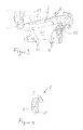
- the projection headlamp invention provides that a pivotable about a horizontal axis of rotation 2 switch panel 3 of a diaphragm device 4 is actuated via a coupling element 6 connected to an electrical adjustment device 5.
- the coupling element 6 is designed as a two-armed lever which has a first lever arm 7 for articulated connection with one end of a linearly movable adjusting bolt 8.
- the adjusting bolt 8 is mounted axially in an electric actuator (electric motor) of the electric adjusting device 5.
- the lever 6 has a second lever arm 9 which is hingedly connected to a lug arm 10 of the switching panel 3.
- the lug arm 10 is - as the switch panel 3 - via a pivot bearing 11, through which the axis of rotation 2 extends, pivotally attached to a fixed aperture 12.
- the fixed panel 12 has on a top side a blend edge 13 which is exposed in an inactive position of the control panel 3 and used to generate a high beam distribution, see Figure 3.
- a blend edge 14 of the control panel 3 is effective for generating a asymmetric low beam distribution.
- the fixed panel 12 serves as a support body for a switch panel 3, which is fixed via the pivot bearing 11 pivotally mounted on the fixed panel 12.
- the fixed aperture 12 serves as a support body for the coupling element 6, which is rotatably mounted on the fixed aperture 12 via a pivot bearing 15 which forms the pivot point of the coupling element 6.
- the fixed aperture 12 serves as a supporting body for the actuator 5, which is connected to fastening points 16 of the fixed aperture with the same by welding (laser welding).
- the adjusting bolt 8 is movably mounted in the horizontal direction between two end positions.
- the coupling element 6 is V-shaped and forming an obtuse opening angle ⁇ laterally outwardly oriented.
- the first lever arm 7 and the second lever arm 9 are arranged inclined in the active position of the diaphragm to a horizontal plane H.
- the actuator 5 In the inactive position of the control panel 3, the actuator 5 is in an energized state, in which the adjusting bolt 8 is arranged in a retracted end position.
- the first lever arm 7 extends substantially in the vertical direction, while the second lever arm 9 is disposed more inclined to the horizontal plane H, see Figure 3.
- the length of the first lever arm 7 and the second lever arm 9 are determined such that upon actuation of the actuator 5 by moving the adjusting bolt 8 by a predetermined stroke, the control panel 3 is pivoted about a defined pivot angle ⁇ between the active position and the inactive position thereof and vice versa ,
- the free end of the adjusting bolt 8 is arranged at an angle and engages in a direction parallel to the axis of rotation 2 extending bore 18 of the free end of the first lever arm 7 a.
- a free end of the second lever arm 9 is pivotally connected to the extension arm 10.
- the lug arm 10 is like the coupling element 6 made of a plastic material.
- the second lever arm 9 is shorter than the first lever arm 7.
- the length of the extension arm 10 between the hinge parts 11 and the free end of the second lever arm 9 is in the region of the length of the first lever arm. 7
- the lever 6 extends substantially upright between the articulation point of the lug arm 10 and the axis of rotation 2 of the switch panel 3 on the one hand and the free end of the adjusting bolt 8 on the other.
Landscapes
- Engineering & Computer Science (AREA)
- General Engineering & Computer Science (AREA)
- Non-Portable Lighting Devices Or Systems Thereof (AREA)
- Lighting Device Outwards From Vehicle And Optical Signal (AREA)
Abstract
Description
- Die Erfindung betrifft einen Projektionsscheinwerfer für Fahrzeuge mit einem Reflektor, mit einer dem Reflektor zugeordneten Lichtquelle, mit einer dem Reflektor in Lichtabstrahlrichtung vorgelagerten Linse, mit einer zwischen der Lichtquelle und der Linse angeordneten Blendeneinrichtung, die eine feststehende Blende zur Erzeugung einer Fernlichtverteilung und einer verstellbare Schaltblende zur Erzeugung einer Abblendlichtverteilung aufweist, mit einer elektrischen Verstelleinrichtung zum Verstellen der Schaltblende, wobei die elektrische Verstelleinrichtung über einen linearbeweglichen Verstellbolzen gelenkig mit der Schaltblende verbunden ist.
- Aus der
EP 0 864 804 B1 ist ein Projektionsscheinwerfer für Fahrzeuge mit einem Reflektor, einer Lichtquelle, einer dem Reflektor in Lichtabstrahlrichtung vorgelagerten Linse, mit einer zwischen der Lichtquelle und der Linse angeordneten Blendeneinrichtung bekannt. Die Blendeneinrichtung umfasst eine feststehende Blende zur Erzeugung einer Fernlichtverteilung sowie eine verstellbare Schaltblende zur Erzeugung einer Abblendlichtverteilung. Eine elektrische Verstelleinrichtung ist vorgesehen zum Verschwenken der Schaltblende. Die elektrische Verstelleinrichtung umfasst einen linear beweglichen Verstellbolzen, der mit der Schaltblende direkt über ein Gelenk verbunden ist. Nachteilig an dem bekannten Projektionsscheinwerfer ist, dass durch die direkte Kopplung zwischen dem Verstellbolzen der Verstelleinrichtung und der Schaltblende eine genaue Abstimmung des Verstellbolzenhubes zu dem Verschwenkwinkelbereich der Schaltblende erforderlich ist.
Aufgabe der vorliegenden Erfindung ist es, einen Projektionsscheinwerfer für Fahrzeuge derart weiterzubilden, dass eine Anpassung des Verstellbolzenhubes einer elektrischen Verstelleinrichtung an den vorgegebenen Schwenkwinkelbereich einer verschwenkbaren Schaltblende gewährleistet ist. - Zur Lösung dieser Aufgabe ist die Erfindung in Verbindung mit dem Oberbegriff des Patentanspruchs 1 dadurch gekennzeichnet, dass der Verstellbolzen über ein schwenkbar an der feststehenden Blende gelagertes Koppelelement mit der Schaltblende gelenkig verbunden ist.
- Der besondere Vorteil der Erfindung besteht darin, dass durch das Vorsehen eines schwenkbaren Koppelelementes, das sich zwischen einem Verstellbolzen der elektrischen Verstelleinrichtung und einer Schaltblende der Blendeneinrichtung erstreckt, der Verstellbolzen indirekt auf die Schaltblende einwirkt. Hierdurch kann eine Anpassung des Verstellbolzenhubes an den Schwenkwinkelbereich der Schaltblende erfolgen. Das Koppelelement dient zur Einstellung der Über- bzw. Untersetzung des Verstellbolzenhubes der elektrischen Verstelleinrichtung zu dem Verschwenkweg der Schaltblende.
- Nach einer bevorzugten Ausführungsform der Erfindung ist das Koppelelement al ein zweiarmiger Hebel ausgebildet, wobei ein erster Hebelarm gelenkig mit dem Verstellbolzen und ein zweiter Hebelarm gelenkig mit der Schaltblende verbunden ist. Die Länge des ersten Hebelarms und/oder des zweiten Hebelarms ist so gewählt, dass ein vorgegebener Verstellbolzenhub die Schaltblende um einen definierten Schwenkwinkel zwischen der Aktivstellung und der Inaktivstellung derselben verschwenkt.
- Nach einer Weiterbildung der Erfindung ist ein Aktor der elektrischen Verstelleinrichtung, in der der Verstellbolzen gelagert ist, durch Schweißen mit der feststehenden Blende verbunden. Hierdurch ist eine stabile und positionsgenaue Befestigung des Aktors gegeben. Durch die reibungsarme Lagerung ergibt sich eine erhöhte Schaltsicherheit.
- Weitere Vorteile der Erfindung ergeben sich aus den weiteren Unteransprüchen.
- Ein Ausführungsbeispiel der Erfindung wird nachfolgend anhand der Zeichnungen näher erläutert.
- Es zeigen:
- Figur 1
- eine schematische Vorderansicht einer Blendeneinrichtung sowie einer elektrischen Verstelleinrichtung eines Projektionsscheinwerfers,
- Figur 2
- eine Vorderansicht der Blendeneinrichtung in einer Aktivstellung einer über ein Koppelelement verschwenkbaren Schaltblende, wobei die elektrische Verstelleinrichtung nicht dargestellt ist,
- Figur 3
- eine Vorderansicht der Blendeneinrichtung in einer Inaktivstellung der Schaltblende unter Weglassung der elektrischen Verstelleinrichtung und
- Figur 4
- eine perspektivische Darstellung des Koppelelementes zur Betätigung der Schaltblende.
- Ein Projektionsscheinwerfer für Fahrzeuge besteht in üblicher Weise aus einem Reflektor, einer dem Reflektor zugeordneten Lichtquelle, einer in Lichtabstrahlrichtung 1 dem Reflektor vorgelagerten Linse und einer Blendeneinrichtung, die nach dem Projektionsprinzip zusammenwirken und in einem Gehäuse angeordnet sind, das durch eine Abdeckscheibe verschlossen ist. Ein solcher Projektionsscheinwerfer ist beispielsweise aus in der
EP 0 864 804 B1 offenbart. - Der erfindungsgemäße Projektionsscheinwerfer sieht vor, dass eine um eine horizontale Drehachse 2 verschwenkbare Schaltblende 3 einer Blendeneinrichtung 4 über ein mit einer elektrischen Verstelleinrichtung 5 verbundenes Koppelelement 6 betätigt wird. Das Koppelelement 6 ist als ein zweiarmiger Hebel ausgebildet, der über einen ersten Hebelarm 7 zur gelenkigen Anbindung mit einem Ende eines linearbewegbaren Verstellbolzens 8 verfügt. Der Verstellbolzen 8 ist axial in einem elektrischen Aktor (elektrischen Motor) der elektrischen Verstelleinrichtung 5 gelagert. Ferner weist der Hebel 6 einen zweiten Hebelarm 9 auf, der gelenkig mit einem Ansatzarm 10 der Schaltblende 3 verbunden ist. Der Ansatzarm 10 ist - wie die Schaltblende 3 - über ein Drehlager 11, durch das die Drehachse 2 verläuft, schwenkbar an einer feststehenden Blende 12 befestigt.
- Die feststehende Blende 12 weist an einer Oberseite eine Blendkante 13 auf, die in einer Inaktivstellung der Schaltblende 3 freigelegt ist und zur Erzeugung einer Fernlichtverteilung dient, siehe Figur 3. In einer Aktivstellung der Schaltblende 3 ist eine Blendkante 14 der Schaltblende 3 wirksam zur Erzeugung einer asymmetrischen Abblendlichtverteilung.
- Die feststehende Blende 12 dient als Tragkörper zum einen für die Schaltblende 3, die über das Drehlager 11 schwenkbar an der feststehenden Blende 12 befestigt ist. Zum zweiten dient die feststehende Blende 12 als Tragkörper für das Koppelelement 6, das über ein Drehlager 15, das den Drehpunkt des Koppelelementes 6 bildet, drehbar an der feststehenden Blende 12 gelagert ist.
- Zum dritten dient die feststehende Blende 12 als Tragkörper für den Aktor 5, der an Befestigungspunkten 16 der feststehenden Blende mit derselben durch Schweißen (Laserschweißen) verbunden ist.
- In dem Aktor 5 ist der Verstellbolzen 8 in horizontaler Richtung zwischen zwei Endstellungen beweglich gelagert. In dem stromlosen Zustand des Aktors 5 ist der Verstellbolzen 8 in einer ausgefahrenen Stellung, wobei das freie Ende des Verstellbolzens 8 in seitlicher Richtung der feststehenden Blende 12 über das Drehlager 15 des Koppelelementes 6 hinausragt. Das Koppelelement 6 ist V-förmig ausgebildet und Bildung eines stumpfen Öffnungswinkels α seitlich nach außen orientiert. Der erste Hebelarm 7 und der zweite Hebelarm 9 sind in der Aktivstellung der Blende geneigt zu einer horizontalen Ebene H angeordnet. Der Scheitel des Hebels 6, der durch das Drehlager 15 gebildet ist. Es erstreckt sich in horizontaler Richtung zwischen einer Stirnfläche 17 der Aktors 5 einerseits und den Enden des ersten Hebelarms 7 und des zweiten Hebelarms 9 andererseits.
- In der Inaktivstellung der Schaltblende 3 ist der Aktor 5 in einem bestromten Zustand, in der der Verstellbolzen 8 in einer eingefahrenen Endstellung angeordnet ist. Der erste Hebelarm 7 erstreckt sich im Wesentlichen in vertikaler Richtung, während der zweite Hebelarm 9 stärker geneigt zu der horizontalen Ebene H angeordnet ist, siehe Figur 3.
- Die Länge des ersten Hebelarms 7 und des zweiten Hebelarms 9 sind derart bestimmt, dass bei Betätigung des Aktors 5 unter Bewegen des Verstellbolzens 8 um einen vorgegebenen Hub die Schaltblende 3 um einen definierten Schwenkwinkel β zwischen der Aktivstellung und der Inaktivstellung derselben und vice versa verschwenkt wird.
- Das freie Ende des Verstellbolzens 8 ist winkelig angeordnet und greift in eine parallel zur Drehachse 2 verlaufende Bohrung 18 des freien Endes des ersten Hebelarms 7 ein. Ein freies Ende des zweiten Hebelarms 9 ist gelenkig mit dem Ansatzarm 10 verbunden. Der Ansatzarm 10 ist wie das Koppelelement 6 aus einem Kunststoffmaterial hergestellt.
- Im vorliegenden Ausführungsbeispiel ist der zweite Hebelarm 9 kürzer ausgebildet als der erste Hebelarm 7. Die Länge des Ansatzarmes 10 zwischen den Gelenkteilen 11 und dem freien Ende des zweiten Hebelarms 9 liegt im Bereich der Länge des ersten Hebelarms 7.
- Der Hebel 6 erstreckt sich im Wesentlichen aufrecht zwischen dem Anlenkungspunkt des Ansatzarms 10 bzw. der Drehachse 2 der Schaltblende 3 einerseits und dem freien Ende des Verstellbolzens 8 andererseits.
Claims (10)
- Projektionsscheinwerfer für Fahrzeuge mit einem Reflektor, mit einer dem Reflektor zugeordneten Lichtquelle, mit einer dem Reflektor in Lichtabstrahlrichtung vorgelagerten Linse, mit einer zwischen der Lichtquelle und der Linse angeordneten Blendeneinrichtung, die eine feststehende Blende zur Erzeugung einer Fernlichtverteilung und einer verstellbare Schaltblende zur Erzeugung einer Abblendlichtverteilung aufweist, mit einer elektrischen Verstelleinrichtung zum Verstellen der Schaltblende, wobei die elektrische Verstelleinrichtung über einen linearbeweglichen Verstellbolzen gelenkig mit der Schaltblende verbunden ist, dadurch gekennzeichnet, dass der Verstellbolzen (8) über ein schwenkbar an der feststehenden Blende (12) gelagertes Koppelelement (6) mit der Schaltblende (3) gelenkig verbunden ist.
- Scheinwerfer nach Anspruch 1, dadurch gekennzeichnet, dass das Koppelelement (6) als ein zweiarmiger Hebel ausgebildet ist, wobei ein erster Hebelarm (7) gelenkig mit dem Verstellbolzen (8) und ein zweiter Hebelarm (9) gelenkig mit der Schaltblende (3) verbunden ist.
- Scheinwerfer nach Anspruch 1 oder 2, dadurch gekennzeichnet, dass die Länge des ersten Hebelarms (7) und/oder des zweiten Hebelarms (9) derart gewählt ist, dass die Schaltblende (3) bei einem vorgegebenen Hub des Verstellbolzens (8) um einen definierten Schwenkwinkel (β) zwischen der oberen Aktivstellung derselben und der unteren Inaktivstellung derselben bewegbar ist.
- Scheinwerfer nach einem der Ansprüche 1 bis 3, dadurch gekennzeichnet, dass der Hebel (6) über ein den Drehpunkt desselben bildendes Drehlager (15) an der feststehenden Blende (12) befestigt ist.
- Scheinwerfer nach einem der Ansprüche 1 bis 4, dadurch gekennzeichnet, dass der Hebel (6) V-förmig ausgebildet ist, wobei ein Drehpunkt des Hebels (6) einen Scheitel bildet und wobei sich der erste Hebelarm (7) und der zweite Hebelarm (9) des Hebels (6) in der Aktivstellung der Schaltblende (3) zu einer horizontalen Ebene (H) geneigt seitlich nach außen hin erstrecken.
- Scheinwerfer nach einem der Ansprüche 1 bis 5, dadurch gekennzeichnet, dass der zweite Hebelarm (9) mit einem Ansatzarm (10) der Schaltblende (3) gelenkig verbunden ist.
- Scheinwerfer nach einem der Ansprüche 1 bis 6, dadurch gekennzeichnet, dass der Ansatzarm (6) zusammen mit der Schaltblende (3) über ein Drehlager (11) schwenkbar an der feststehenden Blende (12) gelagert ist.
- Scheinwerfer nach einem der Ansprüche 1 bis 7, dadurch gekennzeichnet, dass sich der Hebel (6) im Wesentlichen aufrecht zwischen einem freien Ende des Verstellbolzens (8) und einer Drehachse (2) der Schaltblende (3) erstreckt.
- Scheinwerfer nach einem der Ansprüche 1 bis 8, dadurch gekennzeichnet, dass das Koppelelement (6) und/oder der Ansatzarm (10) als Kunststoffbauteil ausgebildet ist.
- Scheinwerfer nach einem der Ansprüche 1 bis 9, dadurch gekennzeichnet, dass die elektrische Verstelleinrichtung (5) einen Aktor aufweist, der durch Schweißen mit der feststehenden Blende (12) verbunden ist.
Applications Claiming Priority (1)
| Application Number | Priority Date | Filing Date | Title |
|---|---|---|---|
| DE102005021706A DE102005021706A1 (de) | 2005-05-11 | 2005-05-11 | Projektionsscheinwerfer für Fahrzeuge |
Publications (3)
| Publication Number | Publication Date |
|---|---|
| EP1722161A2 true EP1722161A2 (de) | 2006-11-15 |
| EP1722161A3 EP1722161A3 (de) | 2008-08-27 |
| EP1722161B1 EP1722161B1 (de) | 2012-02-08 |
Family
ID=36622981
Family Applications (1)
| Application Number | Title | Priority Date | Filing Date |
|---|---|---|---|
| EP06113683A Expired - Lifetime EP1722161B1 (de) | 2005-05-11 | 2006-05-09 | Projektionsscheinwerfer für Fahrzeuge |
Country Status (3)
| Country | Link |
|---|---|
| EP (1) | EP1722161B1 (de) |
| AT (1) | ATE544989T1 (de) |
| DE (1) | DE102005021706A1 (de) |
Citations (2)
| Publication number | Priority date | Publication date | Assignee | Title |
|---|---|---|---|---|
| EP1201980A2 (de) | 2000-10-30 | 2002-05-02 | Framatome Connectors International | Halteeinrichtung für Versorgungsleitungen in Gebäuden |
| EP0864804B1 (de) | 1997-02-28 | 2003-05-14 | Hella KG Hueck & Co. | Fernbetätigbares Einstellsystem für die Blende eines Fahrzeugscheinwerfers |
Family Cites Families (10)
| Publication number | Priority date | Publication date | Assignee | Title |
|---|---|---|---|---|
| GB1504513A (en) * | 1974-03-05 | 1978-03-22 | Lucas Electrical Ltd | Vehicle lamp unit |
| DE19858225A1 (de) * | 1998-12-17 | 2000-06-21 | Hella Kg Hueck & Co | Scheinwerfer für Fahrzeuge |
| IT1307677B1 (it) * | 1999-02-08 | 2001-11-14 | Magneti Marelli Spa | Proiettore per autoveicoli |
| DE19933414B4 (de) * | 1999-07-16 | 2005-02-03 | Automotive Lighting Reutlingen Gmbh | Scheinwerfer für Kraftfahrzeuge |
| JP4101427B2 (ja) * | 2000-03-08 | 2008-06-18 | 株式会社小糸製作所 | 車輌用前照灯 |
| AT413752B (de) * | 2000-03-23 | 2006-05-15 | Zizala Lichtsysteme Gmbh | Fahrzeugscheinwerfer |
| ATA18292000A (de) * | 2000-10-25 | 2005-09-15 | Zizala Lichtsysteme Gmbh | Fahrzeugscheinwerfer |
| DE10216177A1 (de) * | 2002-04-12 | 2003-11-13 | Hella Kg Hueck & Co | Projektionsmodul für einen Fahrzeugscheinwerfer |
| JP4131182B2 (ja) * | 2003-03-17 | 2008-08-13 | 市光工業株式会社 | 車両用前照灯 |
| DE202004020183U1 (de) * | 2004-12-30 | 2005-03-24 | Wang Jen Mao | Umschaltevorrichtung für Fern- und Nahlicht |
-
2005
- 2005-05-11 DE DE102005021706A patent/DE102005021706A1/de not_active Withdrawn
-
2006
- 2006-05-09 AT AT06113683T patent/ATE544989T1/de active
- 2006-05-09 EP EP06113683A patent/EP1722161B1/de not_active Expired - Lifetime
Patent Citations (2)
| Publication number | Priority date | Publication date | Assignee | Title |
|---|---|---|---|---|
| EP0864804B1 (de) | 1997-02-28 | 2003-05-14 | Hella KG Hueck & Co. | Fernbetätigbares Einstellsystem für die Blende eines Fahrzeugscheinwerfers |
| EP1201980A2 (de) | 2000-10-30 | 2002-05-02 | Framatome Connectors International | Halteeinrichtung für Versorgungsleitungen in Gebäuden |
Also Published As
| Publication number | Publication date |
|---|---|
| EP1722161A3 (de) | 2008-08-27 |
| DE102005021706A1 (de) | 2006-11-16 |
| ATE544989T1 (de) | 2012-02-15 |
| EP1722161B1 (de) | 2012-02-08 |
Similar Documents
| Publication | Publication Date | Title |
|---|---|---|
| DE3729515C2 (de) | ||
| EP1234716B1 (de) | Fahrzeugscheinwerfer | |
| DE69721459T2 (de) | Fahrzeugscheinwerfer mit Einstelleinrichtung des Reflektors | |
| DE4306316A1 (en) | Reflector positioner e.g. for varying vehicle headlamp light distribution - involves servomotor in controlled movement of reflector guided by pins engaging in grooves of fixed plate | |
| DE4407108C2 (de) | Fahrzeugscheinwerfer mit einer verstellbaren Blendenanordnung | |
| DE19815107C2 (de) | Ausrichtungsvorrichtung für Fahrzeugleuchten | |
| DE19833431A1 (de) | Kraftfahrzeugscheinwerfer für Abblendlicht und Fernlicht mit einer lageveränderbaren Lichtquelle | |
| DE3902229C2 (de) | ||
| EP2062775B1 (de) | Projektionsscheinwerferanordnung für Fahrzeuge | |
| EP1149731A2 (de) | Scheinwerfer für Fahrzeuge | |
| EP0113365A1 (de) | Scheinwerfer mit verstellbarem reflektor für kraftfahrzeuge. | |
| EP0231924B1 (de) | Elektrischer Schalter, insbesondere Lenkstockschalter für Kraftfahrzeuge | |
| DE3129900C2 (de) | Hebeschiebedach für Kraftfahrzeuge | |
| DE3939710C1 (de) | ||
| EP1201988A2 (de) | Fahrzeugscheinwerfer | |
| WO2016141926A1 (de) | Verstellvorrichtung für scheinwerfer | |
| DE4243174C2 (de) | Kraftfahrzeugscheinwerfer mit einer verstellbaren Blendenanordnung | |
| EP1722161B1 (de) | Projektionsscheinwerfer für Fahrzeuge | |
| DE69809336T2 (de) | Vorrichtung zur Kontrolle der Neigung des Lichtstrahls eines Kfz-Scheinwerfers | |
| AT413752B (de) | Fahrzeugscheinwerfer | |
| DE102009004870A1 (de) | Scheinwerfer für Fahrzeuge | |
| DE19907393C2 (de) | Kraftfahrzeugscheinwerfer für Abblendlicht und Fernlicht mit einer lageveränderbaren Lichtquelle | |
| DE69605063T2 (de) | Scheinwerfer | |
| DE69935763T2 (de) | Kraftfahrzeugscheinwerfer mit elliptischem Reflektor und mit einer schwenkbaren Blende | |
| DE102006056333B4 (de) | Blendenanordnung für eine Lichteinheit |
Legal Events
| Date | Code | Title | Description |
|---|---|---|---|
| PUAI | Public reference made under article 153(3) epc to a published international application that has entered the european phase |
Free format text: ORIGINAL CODE: 0009012 |
|
| AK | Designated contracting states |
Kind code of ref document: A2 Designated state(s): AT BE BG CH CY CZ DE DK EE ES FI FR GB GR HU IE IS IT LI LT LU LV MC NL PL PT RO SE SI SK TR |
|
| AX | Request for extension of the european patent |
Extension state: AL BA HR MK YU |
|
| PUAL | Search report despatched |
Free format text: ORIGINAL CODE: 0009013 |
|
| AK | Designated contracting states |
Kind code of ref document: A3 Designated state(s): AT BE BG CH CY CZ DE DK EE ES FI FR GB GR HU IE IS IT LI LT LU LV MC NL PL PT RO SE SI SK TR |
|
| AX | Request for extension of the european patent |
Extension state: AL BA HR MK YU |
|
| 17P | Request for examination filed |
Effective date: 20090221 |
|
| 17Q | First examination report despatched |
Effective date: 20090409 |
|
| AKX | Designation fees paid |
Designated state(s): AT BE BG CH CY CZ DE DK EE ES FI FR GB GR HU IE IS IT LI LT LU LV MC NL PL PT RO SE SI SK TR |
|
| GRAP | Despatch of communication of intention to grant a patent |
Free format text: ORIGINAL CODE: EPIDOSNIGR1 |
|
| GRAS | Grant fee paid |
Free format text: ORIGINAL CODE: EPIDOSNIGR3 |
|
| GRAA | (expected) grant |
Free format text: ORIGINAL CODE: 0009210 |
|
| AK | Designated contracting states |
Kind code of ref document: B1 Designated state(s): AT BE BG CH CY CZ DE DK EE ES FI FR GB GR HU IE IS IT LI LT LU LV MC NL PL PT RO SE SI SK TR |
|
| REG | Reference to a national code |
Ref country code: GB Ref legal event code: FG4D Free format text: NOT ENGLISH |
|
| REG | Reference to a national code |
Ref country code: DE Ref legal event code: R081 Ref document number: 502006010964 Country of ref document: DE Owner name: HELLA GMBH & CO. KGAA, DE Free format text: FORMER OWNER: HELLA KGAA HUECK & CO., 59557 LIPPSTADT, DE |
|
| REG | Reference to a national code |
Ref country code: CH Ref legal event code: EP Ref country code: AT Ref legal event code: REF Ref document number: 544989 Country of ref document: AT Kind code of ref document: T Effective date: 20120215 |
|
| REG | Reference to a national code |
Ref country code: DE Ref legal event code: R096 Ref document number: 502006010964 Country of ref document: DE Effective date: 20120405 |
|
| REG | Reference to a national code |
Ref country code: NL Ref legal event code: VDEP Effective date: 20120208 |
|
| LTIE | Lt: invalidation of european patent or patent extension |
Effective date: 20120208 |
|
| PG25 | Lapsed in a contracting state [announced via postgrant information from national office to epo] |
Ref country code: LT Free format text: LAPSE BECAUSE OF FAILURE TO SUBMIT A TRANSLATION OF THE DESCRIPTION OR TO PAY THE FEE WITHIN THE PRESCRIBED TIME-LIMIT Effective date: 20120208 Ref country code: NL Free format text: LAPSE BECAUSE OF FAILURE TO SUBMIT A TRANSLATION OF THE DESCRIPTION OR TO PAY THE FEE WITHIN THE PRESCRIBED TIME-LIMIT Effective date: 20120208 Ref country code: IS Free format text: LAPSE BECAUSE OF FAILURE TO SUBMIT A TRANSLATION OF THE DESCRIPTION OR TO PAY THE FEE WITHIN THE PRESCRIBED TIME-LIMIT Effective date: 20120608 |
|
| REG | Reference to a national code |
Ref country code: IE Ref legal event code: FD4D |
|
| PG25 | Lapsed in a contracting state [announced via postgrant information from national office to epo] |
Ref country code: PL Free format text: LAPSE BECAUSE OF FAILURE TO SUBMIT A TRANSLATION OF THE DESCRIPTION OR TO PAY THE FEE WITHIN THE PRESCRIBED TIME-LIMIT Effective date: 20120208 Ref country code: LV Free format text: LAPSE BECAUSE OF FAILURE TO SUBMIT A TRANSLATION OF THE DESCRIPTION OR TO PAY THE FEE WITHIN THE PRESCRIBED TIME-LIMIT Effective date: 20120208 Ref country code: PT Free format text: LAPSE BECAUSE OF FAILURE TO SUBMIT A TRANSLATION OF THE DESCRIPTION OR TO PAY THE FEE WITHIN THE PRESCRIBED TIME-LIMIT Effective date: 20120608 Ref country code: GR Free format text: LAPSE BECAUSE OF FAILURE TO SUBMIT A TRANSLATION OF THE DESCRIPTION OR TO PAY THE FEE WITHIN THE PRESCRIBED TIME-LIMIT Effective date: 20120509 Ref country code: FI Free format text: LAPSE BECAUSE OF FAILURE TO SUBMIT A TRANSLATION OF THE DESCRIPTION OR TO PAY THE FEE WITHIN THE PRESCRIBED TIME-LIMIT Effective date: 20120208 |
|
| PG25 | Lapsed in a contracting state [announced via postgrant information from national office to epo] |
Ref country code: CY Free format text: LAPSE BECAUSE OF FAILURE TO SUBMIT A TRANSLATION OF THE DESCRIPTION OR TO PAY THE FEE WITHIN THE PRESCRIBED TIME-LIMIT Effective date: 20120208 |
|
| PG25 | Lapsed in a contracting state [announced via postgrant information from national office to epo] |
Ref country code: SE Free format text: LAPSE BECAUSE OF FAILURE TO SUBMIT A TRANSLATION OF THE DESCRIPTION OR TO PAY THE FEE WITHIN THE PRESCRIBED TIME-LIMIT Effective date: 20120208 Ref country code: SI Free format text: LAPSE BECAUSE OF FAILURE TO SUBMIT A TRANSLATION OF THE DESCRIPTION OR TO PAY THE FEE WITHIN THE PRESCRIBED TIME-LIMIT Effective date: 20120208 Ref country code: DK Free format text: LAPSE BECAUSE OF FAILURE TO SUBMIT A TRANSLATION OF THE DESCRIPTION OR TO PAY THE FEE WITHIN THE PRESCRIBED TIME-LIMIT Effective date: 20120208 Ref country code: CZ Free format text: LAPSE BECAUSE OF FAILURE TO SUBMIT A TRANSLATION OF THE DESCRIPTION OR TO PAY THE FEE WITHIN THE PRESCRIBED TIME-LIMIT Effective date: 20120208 Ref country code: RO Free format text: LAPSE BECAUSE OF FAILURE TO SUBMIT A TRANSLATION OF THE DESCRIPTION OR TO PAY THE FEE WITHIN THE PRESCRIBED TIME-LIMIT Effective date: 20120208 Ref country code: IE Free format text: LAPSE BECAUSE OF FAILURE TO SUBMIT A TRANSLATION OF THE DESCRIPTION OR TO PAY THE FEE WITHIN THE PRESCRIBED TIME-LIMIT Effective date: 20120208 Ref country code: EE Free format text: LAPSE BECAUSE OF FAILURE TO SUBMIT A TRANSLATION OF THE DESCRIPTION OR TO PAY THE FEE WITHIN THE PRESCRIBED TIME-LIMIT Effective date: 20120208 |
|
| BERE | Be: lapsed |
Owner name: HELLA KGAA HUECK & CO. Effective date: 20120531 |
|
| PG25 | Lapsed in a contracting state [announced via postgrant information from national office to epo] |
Ref country code: IT Free format text: LAPSE BECAUSE OF FAILURE TO SUBMIT A TRANSLATION OF THE DESCRIPTION OR TO PAY THE FEE WITHIN THE PRESCRIBED TIME-LIMIT Effective date: 20120208 Ref country code: SK Free format text: LAPSE BECAUSE OF FAILURE TO SUBMIT A TRANSLATION OF THE DESCRIPTION OR TO PAY THE FEE WITHIN THE PRESCRIBED TIME-LIMIT Effective date: 20120208 |
|
| PLBE | No opposition filed within time limit |
Free format text: ORIGINAL CODE: 0009261 |
|
| STAA | Information on the status of an ep patent application or granted ep patent |
Free format text: STATUS: NO OPPOSITION FILED WITHIN TIME LIMIT |
|
| PG25 | Lapsed in a contracting state [announced via postgrant information from national office to epo] |
Ref country code: MC Free format text: LAPSE BECAUSE OF NON-PAYMENT OF DUE FEES Effective date: 20120531 |
|
| REG | Reference to a national code |
Ref country code: CH Ref legal event code: PL |
|
| 26N | No opposition filed |
Effective date: 20121109 |
|
| PG25 | Lapsed in a contracting state [announced via postgrant information from national office to epo] |
Ref country code: CH Free format text: LAPSE BECAUSE OF NON-PAYMENT OF DUE FEES Effective date: 20120531 Ref country code: LI Free format text: LAPSE BECAUSE OF NON-PAYMENT OF DUE FEES Effective date: 20120531 |
|
| PG25 | Lapsed in a contracting state [announced via postgrant information from national office to epo] |
Ref country code: BE Free format text: LAPSE BECAUSE OF NON-PAYMENT OF DUE FEES Effective date: 20120531 |
|
| REG | Reference to a national code |
Ref country code: DE Ref legal event code: R097 Ref document number: 502006010964 Country of ref document: DE Effective date: 20121109 |
|
| PG25 | Lapsed in a contracting state [announced via postgrant information from national office to epo] |
Ref country code: ES Free format text: LAPSE BECAUSE OF FAILURE TO SUBMIT A TRANSLATION OF THE DESCRIPTION OR TO PAY THE FEE WITHIN THE PRESCRIBED TIME-LIMIT Effective date: 20120519 |
|
| PG25 | Lapsed in a contracting state [announced via postgrant information from national office to epo] |
Ref country code: BG Free format text: LAPSE BECAUSE OF FAILURE TO SUBMIT A TRANSLATION OF THE DESCRIPTION OR TO PAY THE FEE WITHIN THE PRESCRIBED TIME-LIMIT Effective date: 20120508 |
|
| PGFP | Annual fee paid to national office [announced via postgrant information from national office to epo] |
Ref country code: GB Payment date: 20130508 Year of fee payment: 8 |
|
| PG25 | Lapsed in a contracting state [announced via postgrant information from national office to epo] |
Ref country code: TR Free format text: LAPSE BECAUSE OF FAILURE TO SUBMIT A TRANSLATION OF THE DESCRIPTION OR TO PAY THE FEE WITHIN THE PRESCRIBED TIME-LIMIT Effective date: 20120208 |
|
| PG25 | Lapsed in a contracting state [announced via postgrant information from national office to epo] |
Ref country code: LU Free format text: LAPSE BECAUSE OF NON-PAYMENT OF DUE FEES Effective date: 20120509 |
|
| PG25 | Lapsed in a contracting state [announced via postgrant information from national office to epo] |
Ref country code: HU Free format text: LAPSE BECAUSE OF FAILURE TO SUBMIT A TRANSLATION OF THE DESCRIPTION OR TO PAY THE FEE WITHIN THE PRESCRIBED TIME-LIMIT Effective date: 20060509 |
|
| GBPC | Gb: european patent ceased through non-payment of renewal fee |
Effective date: 20140509 |
|
| PG25 | Lapsed in a contracting state [announced via postgrant information from national office to epo] |
Ref country code: GB Free format text: LAPSE BECAUSE OF NON-PAYMENT OF DUE FEES Effective date: 20140509 |
|
| REG | Reference to a national code |
Ref country code: FR Ref legal event code: PLFP Year of fee payment: 11 |
|
| REG | Reference to a national code |
Ref country code: FR Ref legal event code: PLFP Year of fee payment: 12 |
|
| PGFP | Annual fee paid to national office [announced via postgrant information from national office to epo] |
Ref country code: AT Payment date: 20170425 Year of fee payment: 12 |
|
| REG | Reference to a national code |
Ref country code: DE Ref legal event code: R081 Ref document number: 502006010964 Country of ref document: DE Owner name: HELLA GMBH & CO. KGAA, DE Free format text: FORMER OWNER: HELLA KGAA HUECK & CO., 59557 LIPPSTADT, DE |
|
| REG | Reference to a national code |
Ref country code: FR Ref legal event code: PLFP Year of fee payment: 13 |
|
| PGFP | Annual fee paid to national office [announced via postgrant information from national office to epo] |
Ref country code: FR Payment date: 20180411 Year of fee payment: 13 |
|
| REG | Reference to a national code |
Ref country code: AT Ref legal event code: MM01 Ref document number: 544989 Country of ref document: AT Kind code of ref document: T Effective date: 20180509 |
|
| PG25 | Lapsed in a contracting state [announced via postgrant information from national office to epo] |
Ref country code: AT Free format text: LAPSE BECAUSE OF NON-PAYMENT OF DUE FEES Effective date: 20180509 |
|
| PGFP | Annual fee paid to national office [announced via postgrant information from national office to epo] |
Ref country code: DE Payment date: 20190423 Year of fee payment: 14 |
|
| PG25 | Lapsed in a contracting state [announced via postgrant information from national office to epo] |
Ref country code: FR Free format text: LAPSE BECAUSE OF NON-PAYMENT OF DUE FEES Effective date: 20190531 |
|
| REG | Reference to a national code |
Ref country code: DE Ref legal event code: R119 Ref document number: 502006010964 Country of ref document: DE |
|
| PG25 | Lapsed in a contracting state [announced via postgrant information from national office to epo] |
Ref country code: DE Free format text: LAPSE BECAUSE OF NON-PAYMENT OF DUE FEES Effective date: 20201201 |