EP1719721A1 - Sortiereinrichtung - Google Patents
Sortiereinrichtung Download PDFInfo
- Publication number
- EP1719721A1 EP1719721A1 EP06009009A EP06009009A EP1719721A1 EP 1719721 A1 EP1719721 A1 EP 1719721A1 EP 06009009 A EP06009009 A EP 06009009A EP 06009009 A EP06009009 A EP 06009009A EP 1719721 A1 EP1719721 A1 EP 1719721A1
- Authority
- EP
- European Patent Office
- Prior art keywords
- sorting
- carrying elements
- conveyor
- sorting device
- carrying
- Prior art date
- Legal status (The legal status is an assumption and is not a legal conclusion. Google has not performed a legal analysis and makes no representation as to the accuracy of the status listed.)
- Granted
Links
Images


Classifications
-
- B—PERFORMING OPERATIONS; TRANSPORTING
- B65—CONVEYING; PACKING; STORING; HANDLING THIN OR FILAMENTARY MATERIAL
- B65G—TRANSPORT OR STORAGE DEVICES, e.g. CONVEYORS FOR LOADING OR TIPPING, SHOP CONVEYOR SYSTEMS OR PNEUMATIC TUBE CONVEYORS
- B65G47/00—Article or material-handling devices associated with conveyors; Methods employing such devices
- B65G47/74—Feeding, transfer, or discharging devices of particular kinds or types
- B65G47/94—Devices for flexing or tilting travelling structures; Throw-off carriages
- B65G47/96—Devices for tilting links or platform
- B65G47/962—Devices for tilting links or platform tilting about an axis substantially parallel to the conveying direction
- B65G47/965—Devices for tilting links or platform tilting about an axis substantially parallel to the conveying direction tilting about a sided-axis, i.e. the axis is not located near the center-line of the load-carrier
-
- B—PERFORMING OPERATIONS; TRANSPORTING
- B65—CONVEYING; PACKING; STORING; HANDLING THIN OR FILAMENTARY MATERIAL
- B65G—TRANSPORT OR STORAGE DEVICES, e.g. CONVEYORS FOR LOADING OR TIPPING, SHOP CONVEYOR SYSTEMS OR PNEUMATIC TUBE CONVEYORS
- B65G2201/00—Indexing codes relating to handling devices, e.g. conveyors, characterised by the type of product or load being conveyed or handled
- B65G2201/02—Articles
- B65G2201/0235—Containers
- B65G2201/0258—Trays, totes or bins
-
- B—PERFORMING OPERATIONS; TRANSPORTING
- B65—CONVEYING; PACKING; STORING; HANDLING THIN OR FILAMENTARY MATERIAL
- B65G—TRANSPORT OR STORAGE DEVICES, e.g. CONVEYORS FOR LOADING OR TIPPING, SHOP CONVEYOR SYSTEMS OR PNEUMATIC TUBE CONVEYORS
- B65G2201/00—Indexing codes relating to handling devices, e.g. conveyors, characterised by the type of product or load being conveyed or handled
- B65G2201/02—Articles
- B65G2201/0264—Luggage
Definitions
- the present invention relates to a sorting device for sorting products, such as in particular pieces of luggage, comprising a supply conveyor, a sorting conveyor, to which the supply conveyor connects for transferring products to be sorted from the supply conveyor to the sorting conveyor, the sorting conveyor being arranged for selectively delivering products to be sorted to a sorting position during transport in a direction of transport, said sorting conveyor comprising a frame as well as a plurality of carrying elements that are movable along guide means of the frame for supporting a product to be sorted in a group of carrying elements positioned adjacent to each other, each of which carrying elements being pivotable by pivot means about a pivot axis extending parallel to the direction of transport so as to cause a product to slide from said group of adjacent carrying elements to the sorting position.
- Such a sorting device is known from WO-A1-9929601 .
- Said known sorting device comprises a sorting conveyor provided with a plurality of carrying elements being evenly distributed over the length of the sorting conveyor.
- the carrying elements each comprise permanent magnets.
- a supply conveyor transfers containers to the sorting conveyor, with fixed pairs of successive carrying elements of the sorting conveyor taking over the containers.
- the containers in turn carry products such as pieces of luggage.
- Pivot means are provided for sorting out said containers in lateral direction.
- Said pivot means comprise pivot arms, which pivot arms are pivotally connected to the successive carrying elements with one end, alternately on the left-hand side and on the right-hand side, and which are provided with guide wheels at their opposite end, which guide wheels travel in respective opposed parallel guide sections.
- pivot guide sections are provided above or below the guide sections, towards which the guide wheels are guided by suitably actuating a switch element simultaneously both for the front and for the rear carrying element of the pair of carrying elements in question.
- the container Upon pivoting, the container is held by the magnets of the carrying elements, but the product that is present in the container will slide from the container onto a discharge conveyor or a chute or the like under the influence of the force of gravity. After selective pivoting and thus sorting has taken place, the container is transferred to a discharge conveyor again by the sorting conveyor.
- a sorting device as described above is used in luggage handling systems at airports, in particular large airports.
- luggage handling systems capable of handling luggage with increasingly larger capacities/speeds.
- the sorting device according to WO-A1-9929601 has this drawback that a certain degree of synchronisation between the supply conveyor and the sorting conveyor is required in order to realise an adequate transfer of pieces of luggage. In practice this actually implies that the supply conveyor stops after a container has arrived at the end thereof and waits for a suitable moment to transfer the container to the sorting conveyor, which is driven continuously.
- US patent US 6,607,066 B1 describes a tilt-tray sorting device which makes it possible to connect constructionally different trays of adjacent conveying units to obtain fixed combinations of two or maximally three trays so as to jointly form one supporting surface, as it were, for a relatively long product.
- the object of the invention is to provided a sorting device according to the introductory paragraph which makes it possible to achieve a higher sorting capacity than with the sorting device according to WO-A1-9929601 , in spite of the fact that the conveying speed of the sorting conveyor remains unchanged.
- the sorting conveyor comprises connecting means for temporarily interconnecting a group of adjacent carrying elements, so that pivoting of some of the carrying elements of said group of interconnected adjacent carrying elements will cause the other elements of said group of interconnected adjacent carrying elements to pivot along therewith.
- the connecting means used in the present invention make it possible to use dynamic (temporary) combinations of a group of, preferably rigidly, interconnected adjacent carrying elements, wherein it is not possible to vary not only the composition of a group of interconnected adjacent carrying elements but in principle also the number of carrying elements of such a group in dependence on the length of the object to be supported by the interconnected adjacent carrying elements.
- adjacent carrying elements are interconnected, said interconnected adjacent carrying elements are capable only of joint pivoting movement.
- the connecting means are arranged for connecting each carrying element to a carrying element provided upstream thereof, if desired.
- the connecting means comprise a connecting element for each carrying element.
- a connecting element makes it possible to connect a carrying element to an adjacent carrying element, so that it is possible to realise groups of interconnected adjacent carrying elements, whose group size may vary, if desired, by suitably driving the respective connecting elements.
- each of said connecting elements is capable of effecting a direct connection with an adjacent connecting element, which leads to a reliable connection.
- each connecting element preferably comprises a pin, which is inserted into a recess of an adjacent connecting element upon actuation thereof.
- a recess is preferably closed, but this is not necessary within the context of the present invention.
- a connection realised by means of a pin inserted into a recess is a highly reliable engagement.
- this makes it possible to design the pin as a shear pin, so that the pin will shear, without other parts being damaged, in the unhoped-for event of an extremely large force being exerted on the connection between adjacent carrying elements, so that eventually only the shear pin needs to be replaced.
- the pivot means preferably comprise a stationary cam track, along which a cam element of a carrying element can selectively travel so as to selectively pivot the carrying element in question as well as the carrying elements connected therewith.
- a cam element of a carrying element can selectively travel so as to selectively pivot the carrying element in question as well as the carrying elements connected therewith.
- the pivot means comprise a cam element for each carrying element.
- the most appropriate cam element of each group of interconnected carrying elements can be selected for causing said group of carrying elements to pivot.
- the most appropriate cam element will generally be the cam element associated with the carrying element or a carrying element that is located centrally in the group of interconnected carrying elements. In the case of a group of five carrying elements this would mean, for example, that the cam element of the third carrying element is used for pivoting the group of carrying elements, whilst in the case of a group of, for example, six carrying elements the cam element associated with the third or the fourth carrying element will be used for that purpose. It is assumed within this context that the centre of gravity of the object being supported on the respective group of carrying elements will be positioned approximately halfway the length, seen in the direction of transport.
- each cam element can be driven to selectively place the cam element into contact with the cam track or keeping the cam element spaced from the cam track.
- the cam track may comprise a drivable entry portion, which can be selectively moved into or out of the path of movement of cam element.
- the entry portion When the entry portion is positioned in the path of movement of a cam element, the entry portion will lead the cam element to the cam track, whereas the cam element will not travel along the stationary cam track, and pivoting will thus not take place, when, on the contrary, the entry portion is not positioned in the path of movement of a cam element.
- the sorting device comprises separate containers for accommodating the products to be sorted therein, wherein the products to be sorted are each transferred to a group of adjacent carrying elements of the sorting conveyor in a container of the supply conveyor, which group of carrying elements is provided with holding means for holding the container upon pivoting of a carrying platform with a container present thereon, whilst a product being accommodated in the container slides off the container.
- the use of such containers and holding means renders the sorting device highly suitable for handling products of varying dimensions, such as pieces of luggage at airports.
- the holding means prevent the containers themselves from sliding off the carrying elements upon pivoting of the adjacent carrying elements which, incidentally, are temporarily interconnected by the connecting means at that moment.
- the holding means comprise an upright edge for each carrying element, against which the container abuts in the pivoted position of the adjacent carrying elements that support the container. It stands to reason that the height of said upright edges must not be such that it would prevent products from sliding off the container.
- the connecting means comprise an engagement element for each carrying element, which engagement element functions to engage the container.
- the container may form the connecting factor between adjacent carrying elements.
- Said engagement need not by definition take place in a mechanical manner, but it might also be effected by magnetic means.
- a very suitable manner of engagement is realised if the engagement elements are arranged for engaging a side of the container that extends parallel to the direction of transport.
- the container may be clamped between the engagement elements on the one hand and an upright edge provided for each carrying element on the other hand. Consequently, another preferred embodiment is characterised in that the engagement elements are arranged for clamping the container against the upright edge.
- a stable support of the containers by the carrying elements, without any synchronisation between the supply conveyor and the sorting conveyor being required, can be obtained in particular if the dimensions of the containers, seen in the direction of transport, are such that each container is supported by at least three carrying elements on the sorting conveyor.
- the sorting conveyor is an endless conveyor.
- the endless path of the sorting conveyor may extend both in the horizontal plane and in the vertical plane in that case.
- An important advantage of the use of an endless path in the horizontal plane is the fact that the full length of the sorting conveyor, possibly with the exception of the non-rectilinear portions thereof, can be utilised for sorting products, whereas in the case of endless paths extending in the vertical plane only the upper (rectilinear) portion is available for sorting. In the latter case the advantage is that the sorting device requires less space and that it can be incorporated in a rectilinear conveying path.
- detection means are provided for determining on which adjacent carrying elements a product to be sorted is transferred from the supply conveyor to the sorting conveyor, and that control means are provided for driving the connecting means on the basis of information from the detection means for interconnecting the adjacent carrying elements in question.
- the connecting means operate independently of the possible presence of a container on associated carrying elements.
- This is to be understood to include the situation in which the connecting means perform the operations that would be required for connecting adjacent carrying elements via a container not only in the case that such a container is present on the carrying elements in question but also in the case that such a container is not present on the carrying elements in question. In the latter case, the operations are to certain extent unnecessary.
- the preferred embodiment in question has this important advantage that the control system need not be arranged for effecting a connection of carrying elements via the connecting means in dependence on the possible presence of container on the carrying elements in question.
- detection means are furthermore generally provided for determining on which adjacent carrying elements a product to be sorted is transferred from the supply conveyor to the sorting conveyor, and control means are provided for driving the pivot means on the basis of information from the detection means.
- the pivot means may be driven in such a manner that an optimally advantageous mechanical load will act on the connection between adjacent carrying elements.
- control means are arranged for driving the front, and preferably only, cam element associated with a carrying element of a group of adjacent carrying elements interconnected by the connecting means, said associated carrying element being positioned in the centre of the group of interconnected adjacent carrying elements, for selectively placing the driven cam element into contact with a cam track. Since the centre of gravity of a product to be sorted will generally be located at a point halfway the length thereof, it is also advantageous to apply the forces required for pivoting a group of interconnected adjacent carrying elements in the centre of said group of interconnected adjacent carrying elements.
- the pivot axis is located at a position off the centre of the dimension of the carrying elements, seen in horizontal direction transversely to the direction of transport, which leads to a more advantageous mechanical load being exerted on the carrying elements and which, in addition, may enable a reduction of the required height of the sorting device.
- the invention further relates to a method of operating a sorting device for sorting products, such as in particular pieces of luggage, comprising a supply conveyor, a sorting conveyor, to which the supply conveyor connects for transferring products to be sorted from the supply conveyor to the sorting conveyor, the sorting conveyor being arranged for selectively delivering products to be sorted to a sorting position during transport in a direction of transport, said sorting conveyor comprising a frame as well as a plurality of carrying elements that are movable along guide means of the frame for supporting a product to be sorted in a group of carrying elements positioned adjacent to each other, each of which carrying elements being pivotable by pivot means about a pivot axis extending parallel to the direction of transport so as to cause a product to slide from said group of adjacent carrying elements to the sorting position, which method comprises the steps of temporarily interconnecting a group of adjacent carrying elements supporting a product to be sorted and jointly pivoting said group of temporarily interconnected adjacent carrying elements for the purpose of sorting out the product in question in lateral direction.
- said joint pivoting of the group of temporarily interconnected adjacent carrying elements is effected by pivoting only one of the adjacent carrying elements, as a result of which the other carrying elements of said group of temporarily interconnected adjacent carrying elements will pivot along with the carrying element that is being pivoted on account of the fact that said elements are interconnected.
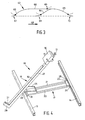
- the sorting device 1 comprises a supply conveyor 2, a sorting conveyor 3 and a discharge conveyor 4.
- the supply conveyor 2 and the discharge conveyor 4 are of the same type, they each comprise two parallel, spaced-apart belts 5, 6 and 7, 8, respectively, which are passed over pulleys.
- the sorting device 1 further comprises a number of containers 9, one empty container of which is shown in more detail in figures 2a and 2b.
- the containers comprise upright walls 10, 11 on the front side and the rear side, respectively, and a hollow bottom 12. No upright wall like the upright walls 10, 11 is provided at the longitudinal edges of said hollow bottom, so that in principle products being supported on the hollow bottom 12 of a container 9 can freely slide off said hollow bottom 12 when the container 9 is pivoted sideways, as is shown in figure 2b.
- the supply conveyor 2 and the sorting conveyor 3 connect to each other in such a manner that transfer of containers 9 containing products 15 to be sorted can take place between the two.
- the sorting conveyor 3 is an endless type of conveyor and comprises two horizontal U-shaped guide sections 13, 14, which extend parallel to each other and which each describe an endless loop in the vertical plane. The open sides of the guide sections 13, 14 face towards each other.
- the sorting conveyor 3 comprises a large number of carrying elements 16 distributed over the length thereof, which elements are attached to an endless chain (not shown) at regularly spaced position. When the chain is driven, the carrying elements are moved in the direction of transport 48 as well.
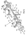
- the carrying elements 16 are each built up of a base part 17 and a load-bearing part 18.
- the load-bearing part 18 is pivotally connected to the base part 17 by means of a pivot pin 19.
- the pivot pin 19 extends parallel to the direction of transport near the guide section 13, at the upper side thereof.
- the base part 17 essentially comprises two transverse strips 20, 21, which are interconnected at one of their two ends via a connecting element 23, and which are interconnected at the opposite end via a hinge element 24, which is provided with the aforesaid pivot pin 19.
- each base part 17 is moreover provided with two guide wheels, which travel between the horizontal legs of the U-shape of the guide sections 13, 14, of which guide wheels only the guide wheels 25, 26 are shown in figure 4.
- the load-bearing part 18 essentially comprises an elongate supporting strip 27, which is provided with a bush 28 at its bottom side, through which the pivot pin 19 extends.
- the supporting strip 27 extends transversely to the direction of transport 48 of the sorting conveyor 3, with the supporting strip 27 extending beyond the guide section 13, seen from the guide section 14, with one end, which end is provided with an upright edge 29.
- each supporting strip is provided with a connecting element 30, which will be discussed in more detail yet with reference to figures 5 - 8b.
- the supporting strip 27 and the inner side of the upright edge 29 are furthermore provided with a lining material 30, 31.
- connecting elements 30 are only shown for those carrying elements that are in a pivoted position. Let there be no mistake about it, however, that since all the carrying elements 16 are of identical construction, all the supporting strips 27 will be provided with a connecting element 30.
- the connecting elements 30 make it possible to connect a supporting strip 27 to an adjacent supporting strip 27.
- the manner in which said connection is effected will be explained in more detail hereinafter in the description of figure 6 in combination with figure 7.
- Figure 6 shows a connecting mechanism 31 for five interconnected connecting elements 30 as present in the upper half of the housing 32 associated with each connecting element 30.
- the mechanism comprises a pin 33, which is capable of reciprocating motion as indicated by the double arrow 34 within the (schematically shown) guide 55, which might be configured as a bore, for example.
- the pin 33 In the position according to the four left-hand connecting elements 30, the pin 33 extends through a hole 35 present in a strip 36 that extends from an adjacent connecting element (also refer to figures 2a and 2b). It will be apparent to those skilled in the art that because of the pin 33 - hole 35 connection between two adjacent connecting elements 30, pivoting of one of the two associated supporting strips 27 will result in pivoting of the other associated supporting strip 27 as well.
- the reciprocating motion of the pin 33 as indicated by the double arrow 34 is effected by means of a linkage consisting of links 37, 38, 39.
- the link 37 can pivot about a pivot pin 40, which takes up a fixed position relative to the housing 32.
- the link 37 is pivotally connected to an end of both the link 38 and the link 39 by means of a pivot pin 41.
- the link 38 can pivot about a pivot pin 42, which takes up a fixed position relative to the housing 32.
- the links 37, 38 are provided with contact bodies 43, 44.
- the link 39 is pivotally connected to an end of the pin 33 by means of a pivot pin 45.
- the cam body 47 can be moved into the path of one of the two contact bodies 43, 44, depending on which of the two contact bodies 43, 44 is positioned more outwardly, by suitably driving the cam body 47 as indicated by the double arrow 46.
- the position in which the cam body 47 extends in the path of one of the two contact bodies 43, 44 is indicated at 47'.
- the cam body 47 would have to be moved to the position 47' before the connecting element 30 passes the cam body 47, causing the cam body 47 to come into contact with the contact body 43 upon movement of the carrying elements 16.
- the links 37, 38 will pivot about respective pivot pins 40, 42 (figure 8a) in the directions indicated by the arrows 49, 50, respectively.
- the link 38 is a link that is made up of a fixed link portion 51 and a pin portion 52 that is rigidly connected thereto, which pin portion has a smaller diameter that the fixed link portion 51 and which is surrounded by a compression spring 53.
- the free end of the pin portion 52 extends into a central bore in the bore portion 54 of the link 38, which bore portion has a length such that the pin portion 52 is capable of reciprocating motion therein in the longitudinal direction thereof.
- the sorting conveyor 3 conveys six containers 9.
- the length of said containers 9, which are identical to each other, is such that each container 9 is supported by five supporting strips 27 associated with five carrying elements 16.
- the five supporting strips 27 in question are interconnected by means of the associated connecting elements 30, in a manner as already described in the foregoing in the description of in particular figures 6, 8a and 8b.
- detection means are used in the sorting device 1, which detect on which adjacent supporting strips 27 a particular container 9 is supported, which information can also be derived from the position the container 9 take up on the supply conveyor 2 at a specific point in time.
- the control system of the sorting device 1 will now drive the cam body 47 to interconnect the supporting strips 27 in question on the basis of information obtained from the detection means.
- a stationary cam track system 62 is provided on the side of the sorting conveyor remote from the chutes 56, 57, in which connection reference is also made to figure 3.
- the cam track system 62 comprises two upwardly sloping cam track portions 63, 64 for sorting products 15 from a container 9 into the respective chutes 56, 57.
- the cam track system 62 comprises a downwardly sloping cam track portion 65 at the end thereof.
- An elevated, horizontally extending cam track portion 65 connects to the upwardly sloping cam track portion 63 on one side and to the downwardly sloping cam track portion 65 on the other side.
- the upwardly sloping cam track portion 63 too, connects to the downwardly sloping cam track portion 65 again.
- the cam track system 62 further comprises four switches 67, 68, 69, 70, a second position of which is illustrated in dotted lines, with a thick dot indicating a pivot point associated with the switch in question.
- a cam wheel 71 on the central (i.e. third) connecting element 30 of the five interconnected connecting elements 30 has been extended outwards in a manner which will be explained in more detail yet in the description of figure 5.
- said cam wheel 71 being extended, said cam wheel will move onto the upwardly sloping cam track portion 63 via said switch 67 upon movement ahead of the sorting conveyor 3, assuming that the switch 67 is in the lower position.
- the connecting elements 30 of the supporting strips 27 in question are subsequently disconnected from each other again by being suitably driven by the control system of the sorting device 1, after which the conveying means 16 are guided downwards and, via the lower return portion of the sorting conveyor 3, upwards again at the beginning of the sorting conveyor 3 for taking over a next container 9 from the supply conveyor 2. Subsequently, a new group of interconnected supporting strips 27 is created again, which group may differ from the previous group as regards the composition thereof. All this depends on the supply of containers 9 via the supply conveyor 2. It is important in this context to note that the supply conveyor 2 need not stop at any point but can continuously supply containers 9 to the sorting conveyor 3.
- a product 15 present in a container 9 is not intended for being sorted into one of the chutes 56, 57, as has been the case, for example, for the product 15 in the container 9 that is just being transferred from the sorting conveyor 3 to the discharge conveyor 4 in figure 1, it can pass the downwardly sloping cam track portion 65 in a possibly extended position of a cam wheel 71 associated with a (central) supporting strip 27 that supports the container 9 in question in that said cam wheel 71 pushes the switch 70 into the upper position (illustrated in dotted lines) against spring action (as with the switch 69).
- a switch 70 might not be required, either, if no cam wheel 71 associated with the supporting strips 27 that support a container 9 carrying a product 15 that is not to be sorted into either one of the two chutes 56, 57 were to be extended at all.
- the cam wheels 71 for all the connecting elements 30 may be in the extended position at all times (and in that sense not be drivable, therefore) and the movement of a central cam wheel 71 associated with a group of interconnected supporting strips 27 over one of the upwardly sloping cam track portions 63, 64 can be controlled by switching the switches 67 to the lower position in a very precisely timed manner, i.e. just before the cam wheel 71 in question arrives at the beginning of the switch 67, 68 in question, but after the downstream cam wheel 71 has passed the (beginning of the) switch 67, 68.
- FIG. 5 shows the extension mechanism 72 (in fivefold) for the five connecting elements 30 as shown in figure 6, which extension mechanism 72 is accommodated in the lower half of the housing 32 of each connecting element 30.
- the extension mechanism 72 comprises two links 137, 138, which are pivotally interconnected at their facing ends and which are pivotable about pivot pins 140 and 142, respectively.
- the links 137 and 138 that are interconnected by the pivot pin 141 are quite similar to the links 37 and 38 that have already been discussed extensively in the foregoing, in particular with reference to figures 8a and 8b.
- a pin 73 extending in line with the associated supporting strips 27 extends below the links 137, 138, on a free end of which the cam wheel 71 is mounted.
- the pin 73 is now mechanically connected to the pivot pin 141 by means of a pin extending perpendicularly to the plane of drawing, which pin may also simply be the extension of the pin member associated with the pivot pin 141.
- the pin extends through a slotted hole that extends in the direction of transport 48. Because of the connection via said slotted hole, the pin 73 is capable of making a rectilinear movement in its longitudinal direction through the guide 255 in spite of the slightly lateral movement that the pivot pin 141 makes while the extension mechanism is being operated. In actual fact it may be necessary to form the pin 73 with a larger diameter than is shown in figure 5. Alternatively it would also be possible to use a connection via a connecting link similar to the connecting link 39 in figure 6 instead of using the slotted hole connection.
- the cam body 147 can be moved to the position 147' (temporarily) by suitably driving the cam body 147, which is positioned at a lower level than the cam body 47 and which is capable of reciprocating vertical movement as indicated by the double arrow 146, so as to cause a cam wheel 71 to slide inwards or, quite the opposite, outwards, as is shown for the central connecting element 30 in figure 5.
- Figure 9 is a plan view of a part of a sorting conveyor 203 that may form part of a sorting device according to a second preferred embodiment of the present invention. Only five supporting strips 227 are shown, which are provided with an upright edge 229 at one end.
- the supporting strips 227 that are shown in figure 9 jointly support a container 209, which is of different construction than the container 1 in the sorting device 1, in any case because an arcuate recess 280, 281 is provided in the vertical longitudinal side walls.
- Each supporting strip 227, which is pivotable just like the supporting strip 27, is provided with a tilting arm 282, which is tiltable relative to the associated supporting strip 227 about a tilt axis 283 extending parallel to the direction of transport of the sorting conveyor 203.
- the tilting arm 282 is provided with a engaging wheel 284, whose radius corresponds to the radius of the arcuate recesses 280, 281.
- said tilting arm 282 is provided with a cam wheel 285, which travels in a stationary cam track 286.
- the engaging wheel 284 can be moved from the non-engaging position as shown in figure 10a to the engaging position as shown in figure 10b. In this way all five contact wheels 284 can be placed into engagement with one of the two vertical longitudinal side walls 209, causing the container 209 to be clamped between the five engaging wheels 284 on the one hand and the five upright edges 229 on the other hand.
- the upright edges 229 might also be provided with a certain convexity directed towards the container 209, whose radius corresponds to the radius of the recess 281.
- the engagement by engaging means of the container 209 for the purpose of ensuring that the container remains on the supporting strips 227, also in the pivoted position of the containers could generally be effected by means of a form-locked or force-locked connection between the supporting strips 227 and the container.
- the tilting arm might also be provided with hook means engaging around the longitudinal edge 290 of the container 209, possibly in a recess in the longitudinal edge 290, rather than with the engaging wheel 284.
- the important advantage of the present preferred embodiment is the fact that no (artificial) intelligence at all is required for interconnecting the supporting strips 227 associated with a particular container 209, and that thus there is no need to drive the engaging wheel 284 in a flexible manner.
- the associated engaging wheel 284 would nevertheless make the inward movement, without this leading to a container 209 being engaged, of course.
- detection means for determining exactly how a container 209 lands on the sorting conveyor 203, at least as far as this would be necessary for interconnecting adjacent supporting strips 227.
- the engaging means as detection means for determining on which adjacent supporting strips 227 a container, or a product to be sorted, is present. This information may subsequently be used in driving the pivot means.
- engaging wheels 284 can be returned from the engaging position shown in figure 10b to the non-engaging position shown in figure 10a by having a cam track 286 extend along a reverse path.
- Figures 11-15 relate to a third preferred embodiment of the sorting device according to the invention.
- adjacent carrying elements are interconnected via the container that is supported by the carrying elements in question.
- FIG 11 shows five adjacent carrying elements, whilst figure 12 shows an individual carrying element 301.
- Each carrying element 301 comprises a baseplate 302 and an elongated supporting strip 304 that is pivotable about a pivot axis 303 with respect to the associated baseplate 302.
- the carrying elements 301 form part of a sorting conveyor, with the base plates 302 being attached in regularly spaced-apart relationship to an endless chain (not shown) that defines an endless path for the carrying elements 301 in the vertical plane, comparable to the situation in the first preferred embodiment as explained inter alia with reference to figure 1.
- the pivot axes 303 extend parallel or at least tangentially relative to the endless conveying path.
- the supporting strips 304 are provided with an upright stop edge 305, against which containers, such as the container 9, being supported on the load-bearing surfaces 306 of a group of adjacent supporting strips 304 are clamped by means of a clamping mechanism 307 at the opposite end of the supporting strip 304 in question.
- the clamping mechanism 307 is shown in more detail in figure 13.
- the clamping mechanism 307 comprises a substantially triangular baseplate 308, which is pivotally journalled with respect to the remaining part of the supporting strip 304 in the bottom corner thereof, about a pivot axis 309 that extends parallel to the pivot axis 303.
- the clamping mechanism 307 is provided with a cam wheel 310, whilst at the location of the corner of the baseplate 308 that faces towards the top page 305 the clamping mechanism 307 is provided with a rubber clamping surface 311.
- a torsion spring 312 is provided on either side of the baseplate 308, coaxially with the pivot axis 309, one leg 313 of which torsion spring presses against the rear side of the clamping surface 311, whilst the other leg 314 presses against part of the supporting strip 304 in a manner that is not shown in detail.
- the clamping mechanism 307 tends to assume the position that is shown in figure 12 in unloaded condition, in which the clamping surface 311 is slightly inclined towards the stop edge 305 and the space between the stop edge 305 and the clamping surface 311 is not large enough for accommodating a container therebetween.
- the clamping mechanism 307 will assume the position as shown for the five carrying elements 301 in figure 11.
- each carrying element 301 In addition to a clamping mechanism 307, each carrying element 301, more specifically each supporting strip 304 thereof, also comprises an extension mechanism 320 at the end opposite the stop edge 305 for selectively extending a cam wheel 321.
- an extension mechanism 320 By (selectively) extending one cam wheel 321 associated with one of the carrying elements 301 that support a specific container, joint pivoting of the carrying elements 301 about the pivot axis 303 can take place because of the joint clamping engagement of the carrying elements 301 on the container in question, with only one cam wheel 321 being extended so as to have said wheel travel over a cam track forming part of a cam track system, such as the cam track system 62 in figure 1. In figure 11 the cam wheel associated with the central carrying element 301 is shown in extended position.
- the cam wheel 321 is provided at the end of a sliding shaft 322, being rotatable about its central axis.
- the sliding shaft 322 is slidably accommodated (in the directions indicated by the double arrow 323) in slide bearings 324 .
- a vertical bore is provided in the sliding shaft 322 between the slide bearings 324, through which an actuating pin 325 extends (also refer to figure 15).
- the actuating pin 325 also extends through a guide groove 326 in the sliding plate 327.
- a compression spring 328 which surrounds the sliding shaft 322, acts between the sliding bearing 324 located nearest the cam wheel 321 and the actuating pin 325.
- the extension mechanism 320 tends to assume the position that is shown in figure 14, in which the cam wheel 321 is retracted and thus remains outside the reach of a cam track.
- a force is exerted on a switch (not shown) in the direction indicated by the arrow 329, which switch can be placed in the path of the actuating pin 325 temporarily, against the action of the compression spring 328, causing the sliding shaft 322 to move out.
- the sliding shaft is now locked in the extended position by means of a locking mechanism 330, which also forms part of the extension mechanism 320.
- the locking mechanism 330 comprises a locking element 331, which extends partly above and partly below the sliding plate 327.
- the locking element 331 is provided with a press-on surface 332 provided with a projecting circumferential edge.
- a compression spring 333 acts between said projecting circumferential edge and the sliding plate 327.
- the locking element 331 comprises a U-shaped part 334 under the sliding plate 327, the upper ends of the legs of which U-shape are connected to the press-on surface 332 via openings provided in the sliding plate 327 for that purpose. Because of the action of the compression spring 333, the horizontal upper edge 335 of the web of the U-shaped part 334 presses against the bottom side of the sliding shaft 322.
- the sliding shaft 322 is provided with a groove at said bottom side, which groove, in the position that is shown in figure 14, extends between the U-shaped part 334 of the locking element 331 and the slide bearing located furthest away from the cam wheel 321.
- the groove Upon extension of the cam wheel 321, the groove will thus be positioned at the same axial position as the U-shaped part 334, which will subsequently move upward on account of the action of the compression spring 333, as a result of which the web of the U-shaped part 334 will fall partially within the groove 336 in question, thus locking the sliding shaft 322 in the extended position thereof.
- Unlocking takes place by means of the cam wheel 310 of the clamping mechanism 307.
- the fact is that the clamping engagement of the container between the clamping surfaces 311 and the stop edges 305 associated with the carrying elements 301 that support the container in question must be released before a container is transferred to a discharge conveyor by the sorting conveyor in question, to which end the cam wheels 310 are pressed down by means of a cam guide so as to pivot the clamping mechanism 307 about the pivot axis 309 from the position in that is shown in figure 12 to the position that is shown in figure 11.
- the present invention may also relate to two-sided sorting devices, in which the sorting of products can take place on two longitudinal sides of the sorting conveyor instead of only on one side, as is the case with the three preferred embodiments as described above.
Landscapes
- Engineering & Computer Science (AREA)
- Mechanical Engineering (AREA)
- Branching, Merging, And Special Transfer Between Conveyors (AREA)
- Discharge Of Articles From Conveyors (AREA)
Applications Claiming Priority (1)
| Application Number | Priority Date | Filing Date | Title |
|---|---|---|---|
| NL1028929A NL1028929C2 (nl) | 2005-05-02 | 2005-05-02 | Sorteerinrichting. |
Publications (2)
| Publication Number | Publication Date |
|---|---|
| EP1719721A1 true EP1719721A1 (de) | 2006-11-08 |
| EP1719721B1 EP1719721B1 (de) | 2013-04-10 |
Family
ID=35517451
Family Applications (1)
| Application Number | Title | Priority Date | Filing Date |
|---|---|---|---|
| EP20060009009 Not-in-force EP1719721B1 (de) | 2005-05-02 | 2006-05-01 | Sortiereinrichtung |
Country Status (2)
| Country | Link |
|---|---|
| EP (1) | EP1719721B1 (de) |
| NL (1) | NL1028929C2 (de) |
Cited By (8)
| Publication number | Priority date | Publication date | Assignee | Title |
|---|---|---|---|---|
| WO2007039163A1 (de) * | 2005-10-03 | 2007-04-12 | Siemens Aktiengesellschaft | Ausricht- und klemmvorrichtung für einen behälterwagen |
| WO2013075714A1 (en) * | 2011-11-21 | 2013-05-30 | Crisplant A/S | Sorting mechanism with dynamic discharge |
| JP2015093726A (ja) * | 2013-11-14 | 2015-05-18 | 株式会社ダイフク | 手荷物搬送用トレイ |
| EP3162742A1 (de) * | 2015-11-02 | 2017-05-03 | Siemens Aktiengesellschaft | Sortiermechanismus mit verteilter steuerung |
| EP2955121B1 (de) * | 2014-06-11 | 2017-11-22 | Schoeller Allibert GmbH | Verwendung eines transportmittels, transport- und verteilersystem und verfahren zum transportieren und verteilen von gütern |
| CH714086A1 (de) * | 2017-08-28 | 2019-02-28 | Wrh Walter Reist Holding Ag | Verfahren und Vorrichtung zum Transferieren von Fördergütern zwischen zwei Fördervorrichtungen sowie ein Fördersystem. |
| US10549929B2 (en) | 2017-08-28 | 2020-02-04 | Wrh Walter Reist Holding Ag | Conveying facility |
| EP3608264A1 (de) * | 2018-08-09 | 2020-02-12 | BEUMER Group GmbH & Co. KG | Transportvorrichtung zum transportieren von stückgutteilen |
Families Citing this family (2)
| Publication number | Priority date | Publication date | Assignee | Title |
|---|---|---|---|---|
| CH710660A1 (de) | 2015-01-29 | 2016-07-29 | Wrh Walter Reist Holding Ag | Fördereinheit für eine Fördereinrichtung und Fördereinrichtung mit wenigstens einer solchen Fördereinheit. |
| CN110817382B (zh) * | 2019-11-13 | 2020-12-22 | 中国民航大学 | 一种双向控制的导向传送带装置 |
Citations (5)
| Publication number | Priority date | Publication date | Assignee | Title |
|---|---|---|---|---|
| US3147845A (en) * | 1961-01-10 | 1964-09-08 | Prospect Mfg Co Inc | Sortation means |
| DE1263600B (de) * | 1963-06-19 | 1968-03-14 | Aerojet General Co | Endloser Verteilfoerderer |
| US4031998A (en) * | 1975-03-20 | 1977-06-28 | Rapistan, Incorporated | Automatic sorting conveyor systems |
| JPS59217524A (ja) * | 1983-05-24 | 1984-12-07 | Iseki & Co Ltd | コンベア |
| US6607066B1 (en) * | 1998-07-10 | 2003-08-19 | Crisplant A/S | Conveyor |
-
2005
- 2005-05-02 NL NL1028929A patent/NL1028929C2/nl not_active IP Right Cessation
-
2006
- 2006-05-01 EP EP20060009009 patent/EP1719721B1/de not_active Not-in-force
Patent Citations (5)
| Publication number | Priority date | Publication date | Assignee | Title |
|---|---|---|---|---|
| US3147845A (en) * | 1961-01-10 | 1964-09-08 | Prospect Mfg Co Inc | Sortation means |
| DE1263600B (de) * | 1963-06-19 | 1968-03-14 | Aerojet General Co | Endloser Verteilfoerderer |
| US4031998A (en) * | 1975-03-20 | 1977-06-28 | Rapistan, Incorporated | Automatic sorting conveyor systems |
| JPS59217524A (ja) * | 1983-05-24 | 1984-12-07 | Iseki & Co Ltd | コンベア |
| US6607066B1 (en) * | 1998-07-10 | 2003-08-19 | Crisplant A/S | Conveyor |
Non-Patent Citations (1)
| Title |
|---|
| PATENT ABSTRACTS OF JAPAN vol. 009, no. 092 (M - 373) 20 April 1985 (1985-04-20) * |
Cited By (23)
| Publication number | Priority date | Publication date | Assignee | Title |
|---|---|---|---|---|
| WO2007039163A1 (de) * | 2005-10-03 | 2007-04-12 | Siemens Aktiengesellschaft | Ausricht- und klemmvorrichtung für einen behälterwagen |
| CN104093651B (zh) * | 2011-11-21 | 2016-12-21 | 伯曼集团股份公司 | 分类机构、分类系统和用于清空分类机构中的容器的方法 |
| WO2013075714A1 (en) * | 2011-11-21 | 2013-05-30 | Crisplant A/S | Sorting mechanism with dynamic discharge |
| CN104093651A (zh) * | 2011-11-21 | 2014-10-08 | 克瑞斯普兰股份有限公司 | 具有动态卸载的分类机构 |
| JP2015501770A (ja) * | 2011-11-21 | 2015-01-19 | クリスプラント アクティーゼルスカブ | 動的な荷下ろしを伴う仕分け機構 |
| US10494193B2 (en) | 2011-11-21 | 2019-12-03 | Beumer Group A/S | Sorting mechanism with dynamic discharge |
| US9878852B2 (en) | 2011-11-21 | 2018-01-30 | Beumer Group A/S | Sorting mechanism with dynamic discharge |
| WO2015072279A1 (ja) * | 2013-11-14 | 2015-05-21 | 株式会社ダイフク | 手荷物搬送用トレイ |
| US9950828B2 (en) | 2013-11-14 | 2018-04-24 | Daifuku Co., Ltd. | Baggage conveyance tray |
| TWI579219B (zh) * | 2013-11-14 | 2017-04-21 | Daifuku Kk | Hand pouch for pallets |
| JP2015093726A (ja) * | 2013-11-14 | 2015-05-18 | 株式会社ダイフク | 手荷物搬送用トレイ |
| EP3070020A4 (de) * | 2013-11-14 | 2017-04-05 | Daifuku Co., Ltd. | Gepäckförderungstablett |
| AU2014347960B2 (en) * | 2013-11-14 | 2017-10-12 | Daifuku Co., Ltd. | Baggage conveyance tray |
| RU2641455C2 (ru) * | 2013-11-14 | 2018-01-17 | Дайфуку Ко., Лтд. | Поддон для транспортировки багажа |
| EP3070020A1 (de) * | 2013-11-14 | 2016-09-21 | Daifuku Co., Ltd. | Gepäckförderungstablett |
| EP2955121B1 (de) * | 2014-06-11 | 2017-11-22 | Schoeller Allibert GmbH | Verwendung eines transportmittels, transport- und verteilersystem und verfahren zum transportieren und verteilen von gütern |
| WO2017076541A1 (de) * | 2015-11-02 | 2017-05-11 | Siemens Aktiengesellschaft | Sortiermechanismus mit verteilter steuerung |
| CN108349667A (zh) * | 2015-11-02 | 2018-07-31 | 西门子股份公司 | 具有分布式控制装置的分拣机构 |
| EP3162742A1 (de) * | 2015-11-02 | 2017-05-03 | Siemens Aktiengesellschaft | Sortiermechanismus mit verteilter steuerung |
| CH714086A1 (de) * | 2017-08-28 | 2019-02-28 | Wrh Walter Reist Holding Ag | Verfahren und Vorrichtung zum Transferieren von Fördergütern zwischen zwei Fördervorrichtungen sowie ein Fördersystem. |
| US10549929B2 (en) | 2017-08-28 | 2020-02-04 | Wrh Walter Reist Holding Ag | Conveying facility |
| US11198566B2 (en) | 2017-08-28 | 2021-12-14 | Wrh Walter Reist Holding Ag | Method and device for transferring conveyed items between two conveying appliances, as well as a conveying system |
| EP3608264A1 (de) * | 2018-08-09 | 2020-02-12 | BEUMER Group GmbH & Co. KG | Transportvorrichtung zum transportieren von stückgutteilen |
Also Published As
| Publication number | Publication date |
|---|---|
| EP1719721B1 (de) | 2013-04-10 |
| NL1028929C2 (nl) | 2006-11-03 |
Similar Documents
| Publication | Publication Date | Title |
|---|---|---|
| EP1719721B1 (de) | Sortiereinrichtung | |
| EP2305582B2 (de) | Sortiervorrichtung, insbesondere für Gepäckstücke | |
| US20040007439A1 (en) | System for transferring conveyed items piece by piece | |
| EP0977694B1 (de) | Förderer mit federndem föderband und hochgeschwindigkeits-entlademöglichkeiten | |
| AU705403B2 (en) | Belt accumulation conveyor | |
| NL2005893C2 (nl) | Systeem en werkwijze voor het bufferen van bagagestukken. | |
| US8245835B2 (en) | Sorting apparatus | |
| US5735380A (en) | Suspended storage apparatus | |
| US4259826A (en) | Case packing machine | |
| CA2354979C (en) | Apparatus for stacking elongated members | |
| JPH11503363A (ja) | コンベヤセルマトリックスを使用して物品を仕分ける方法及び装置 | |
| WO1998051597A1 (en) | Conveyor with integrated self-actuating clamp | |
| NL2001922C (en) | An apparatus for transport and controlled discharge of products. | |
| JP5915883B2 (ja) | 物品仕分方法と物品仕分装置 | |
| KR20090008165U (ko) | 계란이 안치된 난좌의 이송 및 적재장치 | |
| US6409647B1 (en) | Device for assembling collapsible containers | |
| JP2004345820A (ja) | 重力式流動棚装置 | |
| NL1015345C1 (nl) | Werkwijze en inrichting voor het verplaatsen van met losse voorwerpen gevulde zakken. | |
| JP3791392B2 (ja) | 転換設備 | |
| SU1705190A1 (ru) | Устройство дл загрузки контейнеров издели ми | |
| CA2468455C (en) | Conveyor having a cushioned belt and high speed discharge capabilities | |
| KR970003216B1 (ko) | 다중 저장 시스템 | |
| SU1247335A1 (ru) | Устройство дл поштучной выдачи длинномерных цилиндрических изделий | |
| SU1375543A1 (ru) | Система дл пакетировани грузов на поддоны и их транспортировани | |
| JPH0546806U (ja) | 自動倉庫 |
Legal Events
| Date | Code | Title | Description |
|---|---|---|---|
| PUAI | Public reference made under article 153(3) epc to a published international application that has entered the european phase |
Free format text: ORIGINAL CODE: 0009012 |
|
| AK | Designated contracting states |
Kind code of ref document: A1 Designated state(s): AT BE BG CH CY CZ DE DK EE ES FI FR GB GR HU IE IS IT LI LT LU LV MC NL PL PT RO SE SI SK TR |
|
| AX | Request for extension of the european patent |
Extension state: AL BA HR MK YU |
|
| 17P | Request for examination filed |
Effective date: 20070501 |
|
| AKX | Designation fees paid |
Designated state(s): AT BE BG CH CY CZ DE DK EE ES FI FR GB GR HU IE IS IT LI LT LU LV MC NL PL PT RO SE SI SK TR |
|
| 17Q | First examination report despatched |
Effective date: 20070704 |
|
| GRAP | Despatch of communication of intention to grant a patent |
Free format text: ORIGINAL CODE: EPIDOSNIGR1 |
|
| GRAS | Grant fee paid |
Free format text: ORIGINAL CODE: EPIDOSNIGR3 |
|
| GRAA | (expected) grant |
Free format text: ORIGINAL CODE: 0009210 |
|
| AK | Designated contracting states |
Kind code of ref document: B1 Designated state(s): AT BE BG CH CY CZ DE DK EE ES FI FR GB GR HU IE IS IT LI LT LU LV MC NL PL PT RO SE SI SK TR |
|
| REG | Reference to a national code |
Ref country code: GB Ref legal event code: FG4D |
|
| REG | Reference to a national code |
Ref country code: CH Ref legal event code: EP Ref country code: AT Ref legal event code: REF Ref document number: 605869 Country of ref document: AT Kind code of ref document: T Effective date: 20130415 |
|
| RAP2 | Party data changed (patent owner data changed or rights of a patent transferred) |
Owner name: VANDERLANDE INDUSTRIES B.V. |
|
| REG | Reference to a national code |
Ref country code: IE Ref legal event code: FG4D |
|
| REG | Reference to a national code |
Ref country code: DE Ref legal event code: R096 Ref document number: 602006035515 Country of ref document: DE Effective date: 20130606 |
|
| REG | Reference to a national code |
Ref country code: NL Ref legal event code: T3 |
|
| PG25 | Lapsed in a contracting state [announced via postgrant information from national office to epo] |
Ref country code: SI Free format text: LAPSE BECAUSE OF FAILURE TO SUBMIT A TRANSLATION OF THE DESCRIPTION OR TO PAY THE FEE WITHIN THE PRESCRIBED TIME-LIMIT Effective date: 20130410 |
|
| REG | Reference to a national code |
Ref country code: AT Ref legal event code: MK05 Ref document number: 605869 Country of ref document: AT Kind code of ref document: T Effective date: 20130410 |
|
| REG | Reference to a national code |
Ref country code: LT Ref legal event code: MG4D |
|
| PG25 | Lapsed in a contracting state [announced via postgrant information from national office to epo] |
Ref country code: BE Free format text: LAPSE BECAUSE OF FAILURE TO SUBMIT A TRANSLATION OF THE DESCRIPTION OR TO PAY THE FEE WITHIN THE PRESCRIBED TIME-LIMIT Effective date: 20130410 Ref country code: PT Free format text: LAPSE BECAUSE OF FAILURE TO SUBMIT A TRANSLATION OF THE DESCRIPTION OR TO PAY THE FEE WITHIN THE PRESCRIBED TIME-LIMIT Effective date: 20130812 Ref country code: LT Free format text: LAPSE BECAUSE OF FAILURE TO SUBMIT A TRANSLATION OF THE DESCRIPTION OR TO PAY THE FEE WITHIN THE PRESCRIBED TIME-LIMIT Effective date: 20130410 Ref country code: AT Free format text: LAPSE BECAUSE OF FAILURE TO SUBMIT A TRANSLATION OF THE DESCRIPTION OR TO PAY THE FEE WITHIN THE PRESCRIBED TIME-LIMIT Effective date: 20130410 Ref country code: IS Free format text: LAPSE BECAUSE OF FAILURE TO SUBMIT A TRANSLATION OF THE DESCRIPTION OR TO PAY THE FEE WITHIN THE PRESCRIBED TIME-LIMIT Effective date: 20130810 Ref country code: GR Free format text: LAPSE BECAUSE OF FAILURE TO SUBMIT A TRANSLATION OF THE DESCRIPTION OR TO PAY THE FEE WITHIN THE PRESCRIBED TIME-LIMIT Effective date: 20130711 Ref country code: SE Free format text: LAPSE BECAUSE OF FAILURE TO SUBMIT A TRANSLATION OF THE DESCRIPTION OR TO PAY THE FEE WITHIN THE PRESCRIBED TIME-LIMIT Effective date: 20130410 Ref country code: ES Free format text: LAPSE BECAUSE OF FAILURE TO SUBMIT A TRANSLATION OF THE DESCRIPTION OR TO PAY THE FEE WITHIN THE PRESCRIBED TIME-LIMIT Effective date: 20130721 Ref country code: FI Free format text: LAPSE BECAUSE OF FAILURE TO SUBMIT A TRANSLATION OF THE DESCRIPTION OR TO PAY THE FEE WITHIN THE PRESCRIBED TIME-LIMIT Effective date: 20130410 |
|
| PG25 | Lapsed in a contracting state [announced via postgrant information from national office to epo] |
Ref country code: BG Free format text: LAPSE BECAUSE OF FAILURE TO SUBMIT A TRANSLATION OF THE DESCRIPTION OR TO PAY THE FEE WITHIN THE PRESCRIBED TIME-LIMIT Effective date: 20130710 Ref country code: PL Free format text: LAPSE BECAUSE OF FAILURE TO SUBMIT A TRANSLATION OF THE DESCRIPTION OR TO PAY THE FEE WITHIN THE PRESCRIBED TIME-LIMIT Effective date: 20130410 Ref country code: LV Free format text: LAPSE BECAUSE OF FAILURE TO SUBMIT A TRANSLATION OF THE DESCRIPTION OR TO PAY THE FEE WITHIN THE PRESCRIBED TIME-LIMIT Effective date: 20130410 Ref country code: CY Free format text: LAPSE BECAUSE OF FAILURE TO SUBMIT A TRANSLATION OF THE DESCRIPTION OR TO PAY THE FEE WITHIN THE PRESCRIBED TIME-LIMIT Effective date: 20130410 |
|
| REG | Reference to a national code |
Ref country code: CH Ref legal event code: PL |
|
| PG25 | Lapsed in a contracting state [announced via postgrant information from national office to epo] |
Ref country code: DK Free format text: LAPSE BECAUSE OF FAILURE TO SUBMIT A TRANSLATION OF THE DESCRIPTION OR TO PAY THE FEE WITHIN THE PRESCRIBED TIME-LIMIT Effective date: 20130410 Ref country code: CZ Free format text: LAPSE BECAUSE OF FAILURE TO SUBMIT A TRANSLATION OF THE DESCRIPTION OR TO PAY THE FEE WITHIN THE PRESCRIBED TIME-LIMIT Effective date: 20130410 Ref country code: SK Free format text: LAPSE BECAUSE OF FAILURE TO SUBMIT A TRANSLATION OF THE DESCRIPTION OR TO PAY THE FEE WITHIN THE PRESCRIBED TIME-LIMIT Effective date: 20130410 Ref country code: MC Free format text: LAPSE BECAUSE OF FAILURE TO SUBMIT A TRANSLATION OF THE DESCRIPTION OR TO PAY THE FEE WITHIN THE PRESCRIBED TIME-LIMIT Effective date: 20130410 Ref country code: LI Free format text: LAPSE BECAUSE OF NON-PAYMENT OF DUE FEES Effective date: 20130531 Ref country code: CH Free format text: LAPSE BECAUSE OF NON-PAYMENT OF DUE FEES Effective date: 20130531 Ref country code: EE Free format text: LAPSE BECAUSE OF FAILURE TO SUBMIT A TRANSLATION OF THE DESCRIPTION OR TO PAY THE FEE WITHIN THE PRESCRIBED TIME-LIMIT Effective date: 20130410 |
|
| PLBE | No opposition filed within time limit |
Free format text: ORIGINAL CODE: 0009261 |
|
| STAA | Information on the status of an ep patent application or granted ep patent |
Free format text: STATUS: NO OPPOSITION FILED WITHIN TIME LIMIT |
|
| REG | Reference to a national code |
Ref country code: IE Ref legal event code: MM4A |
|
| PG25 | Lapsed in a contracting state [announced via postgrant information from national office to epo] |
Ref country code: RO Free format text: LAPSE BECAUSE OF FAILURE TO SUBMIT A TRANSLATION OF THE DESCRIPTION OR TO PAY THE FEE WITHIN THE PRESCRIBED TIME-LIMIT Effective date: 20130410 Ref country code: IT Free format text: LAPSE BECAUSE OF FAILURE TO SUBMIT A TRANSLATION OF THE DESCRIPTION OR TO PAY THE FEE WITHIN THE PRESCRIBED TIME-LIMIT Effective date: 20130410 |
|
| 26N | No opposition filed |
Effective date: 20140113 |
|
| REG | Reference to a national code |
Ref country code: DE Ref legal event code: R097 Ref document number: 602006035515 Country of ref document: DE Effective date: 20140113 |
|
| PG25 | Lapsed in a contracting state [announced via postgrant information from national office to epo] |
Ref country code: IE Free format text: LAPSE BECAUSE OF NON-PAYMENT OF DUE FEES Effective date: 20130501 |
|
| REG | Reference to a national code |
Ref country code: FR Ref legal event code: PLFP Year of fee payment: 10 |
|
| PG25 | Lapsed in a contracting state [announced via postgrant information from national office to epo] |
Ref country code: TR Free format text: LAPSE BECAUSE OF FAILURE TO SUBMIT A TRANSLATION OF THE DESCRIPTION OR TO PAY THE FEE WITHIN THE PRESCRIBED TIME-LIMIT Effective date: 20130410 |
|
| PG25 | Lapsed in a contracting state [announced via postgrant information from national office to epo] |
Ref country code: LU Free format text: LAPSE BECAUSE OF NON-PAYMENT OF DUE FEES Effective date: 20130501 Ref country code: HU Free format text: LAPSE BECAUSE OF FAILURE TO SUBMIT A TRANSLATION OF THE DESCRIPTION OR TO PAY THE FEE WITHIN THE PRESCRIBED TIME-LIMIT; INVALID AB INITIO Effective date: 20060501 |
|
| PGFP | Annual fee paid to national office [announced via postgrant information from national office to epo] |
Ref country code: GB Payment date: 20150521 Year of fee payment: 10 Ref country code: DE Payment date: 20150521 Year of fee payment: 10 |
|
| PGFP | Annual fee paid to national office [announced via postgrant information from national office to epo] |
Ref country code: NL Payment date: 20150520 Year of fee payment: 10 Ref country code: FR Payment date: 20150521 Year of fee payment: 10 |
|
| REG | Reference to a national code |
Ref country code: DE Ref legal event code: R119 Ref document number: 602006035515 Country of ref document: DE |
|
| REG | Reference to a national code |
Ref country code: NL Ref legal event code: MM Effective date: 20160601 |
|
| GBPC | Gb: european patent ceased through non-payment of renewal fee |
Effective date: 20160501 |
|
| PG25 | Lapsed in a contracting state [announced via postgrant information from national office to epo] |
Ref country code: NL Free format text: LAPSE BECAUSE OF NON-PAYMENT OF DUE FEES Effective date: 20160601 |
|
| REG | Reference to a national code |
Ref country code: FR Ref legal event code: ST Effective date: 20170131 |
|
| PG25 | Lapsed in a contracting state [announced via postgrant information from national office to epo] |
Ref country code: FR Free format text: LAPSE BECAUSE OF NON-PAYMENT OF DUE FEES Effective date: 20160531 Ref country code: DE Free format text: LAPSE BECAUSE OF NON-PAYMENT OF DUE FEES Effective date: 20161201 |
|
| PG25 | Lapsed in a contracting state [announced via postgrant information from national office to epo] |
Ref country code: GB Free format text: LAPSE BECAUSE OF NON-PAYMENT OF DUE FEES Effective date: 20160501 |