EP1719585B1 - Maschine zur Bearbeitung von optischen Werkstücken, namentlich Kunststoff-Brillengläsern - Google Patents
Maschine zur Bearbeitung von optischen Werkstücken, namentlich Kunststoff-Brillengläsern Download PDFInfo
- Publication number
- EP1719585B1 EP1719585B1 EP06006637A EP06006637A EP1719585B1 EP 1719585 B1 EP1719585 B1 EP 1719585B1 EP 06006637 A EP06006637 A EP 06006637A EP 06006637 A EP06006637 A EP 06006637A EP 1719585 B1 EP1719585 B1 EP 1719585B1
- Authority
- EP
- European Patent Office
- Prior art keywords
- workpiece
- axis
- plane
- tool
- fast
- Prior art date
- Legal status (The legal status is an assumption and is not a legal conclusion. Google has not performed a legal analysis and makes no representation as to the accuracy of the status listed.)
- Active
Links
- 238000003754 machining Methods 0.000 title claims abstract description 14
- 230000003287 optical effect Effects 0.000 title claims description 11
- 238000005520 cutting process Methods 0.000 claims abstract description 27
- 230000033001 locomotion Effects 0.000 claims description 38
- 238000000034 method Methods 0.000 claims description 17
- 230000001154 acute effect Effects 0.000 abstract 1
- 238000003801 milling Methods 0.000 description 22
- 230000007246 mechanism Effects 0.000 description 3
- 230000000750 progressive effect Effects 0.000 description 3
- 230000000712 assembly Effects 0.000 description 2
- 238000000429 assembly Methods 0.000 description 2
- 239000011248 coating agent Substances 0.000 description 2
- 238000000576 coating method Methods 0.000 description 2
- 230000007547 defect Effects 0.000 description 2
- 229910003460 diamond Inorganic materials 0.000 description 2
- 239000010432 diamond Substances 0.000 description 2
- 238000006073 displacement reaction Methods 0.000 description 2
- 239000000463 material Substances 0.000 description 2
- 239000007787 solid Substances 0.000 description 2
- 230000000903 blocking effect Effects 0.000 description 1
- 229910052799 carbon Inorganic materials 0.000 description 1
- 230000001276 controlling effect Effects 0.000 description 1
- 238000011161 development Methods 0.000 description 1
- 230000018109 developmental process Effects 0.000 description 1
- 238000000227 grinding Methods 0.000 description 1
- 238000004519 manufacturing process Methods 0.000 description 1
- 230000002093 peripheral effect Effects 0.000 description 1
- 238000005498 polishing Methods 0.000 description 1
- 238000007517 polishing process Methods 0.000 description 1
- 230000001105 regulatory effect Effects 0.000 description 1
- 230000000717 retained effect Effects 0.000 description 1
- 230000035945 sensitivity Effects 0.000 description 1
- 238000007493 shaping process Methods 0.000 description 1
- 238000004381 surface treatment Methods 0.000 description 1
Images


Classifications
-
- B—PERFORMING OPERATIONS; TRANSPORTING
- B24—GRINDING; POLISHING
- B24B—MACHINES, DEVICES, OR PROCESSES FOR GRINDING OR POLISHING; DRESSING OR CONDITIONING OF ABRADING SURFACES; FEEDING OF GRINDING, POLISHING, OR LAPPING AGENTS
- B24B47/00—Drives or gearings; Equipment therefor
- B24B47/22—Equipment for exact control of the position of the grinding tool or work at the start of the grinding operation
-
- B—PERFORMING OPERATIONS; TRANSPORTING
- B23—MACHINE TOOLS; METAL-WORKING NOT OTHERWISE PROVIDED FOR
- B23Q—DETAILS, COMPONENTS, OR ACCESSORIES FOR MACHINE TOOLS, e.g. ARRANGEMENTS FOR COPYING OR CONTROLLING; MACHINE TOOLS IN GENERAL CHARACTERISED BY THE CONSTRUCTION OF PARTICULAR DETAILS OR COMPONENTS; COMBINATIONS OR ASSOCIATIONS OF METAL-WORKING MACHINES, NOT DIRECTED TO A PARTICULAR RESULT
- B23Q1/00—Members which are comprised in the general build-up of a form of machine, particularly relatively large fixed members
- B23Q1/25—Movable or adjustable work or tool supports
- B23Q1/44—Movable or adjustable work or tool supports using particular mechanisms
- B23Q1/56—Movable or adjustable work or tool supports using particular mechanisms with sliding pairs only, the sliding pairs being the first two elements of the mechanism
- B23Q1/60—Movable or adjustable work or tool supports using particular mechanisms with sliding pairs only, the sliding pairs being the first two elements of the mechanism two sliding pairs only, the sliding pairs being the first two elements of the mechanism
-
- B—PERFORMING OPERATIONS; TRANSPORTING
- B24—GRINDING; POLISHING
- B24B—MACHINES, DEVICES, OR PROCESSES FOR GRINDING OR POLISHING; DRESSING OR CONDITIONING OF ABRADING SURFACES; FEEDING OF GRINDING, POLISHING, OR LAPPING AGENTS
- B24B13/00—Machines or devices designed for grinding or polishing optical surfaces on lenses or surfaces of similar shape on other work; Accessories therefor
- B24B13/04—Machines or devices designed for grinding or polishing optical surfaces on lenses or surfaces of similar shape on other work; Accessories therefor grinding of lenses involving grinding wheels controlled by gearing
- B24B13/046—Machines or devices designed for grinding or polishing optical surfaces on lenses or surfaces of similar shape on other work; Accessories therefor grinding of lenses involving grinding wheels controlled by gearing using a pointed tool or scraper-like tool
-
- B—PERFORMING OPERATIONS; TRANSPORTING
- B24—GRINDING; POLISHING
- B24B—MACHINES, DEVICES, OR PROCESSES FOR GRINDING OR POLISHING; DRESSING OR CONDITIONING OF ABRADING SURFACES; FEEDING OF GRINDING, POLISHING, OR LAPPING AGENTS
- B24B13/00—Machines or devices designed for grinding or polishing optical surfaces on lenses or surfaces of similar shape on other work; Accessories therefor
- B24B13/06—Machines or devices designed for grinding or polishing optical surfaces on lenses or surfaces of similar shape on other work; Accessories therefor grinding of lenses, the tool or work being controlled by information-carrying means, e.g. patterns, punched tapes, magnetic tapes
-
- B—PERFORMING OPERATIONS; TRANSPORTING
- B24—GRINDING; POLISHING
- B24B—MACHINES, DEVICES, OR PROCESSES FOR GRINDING OR POLISHING; DRESSING OR CONDITIONING OF ABRADING SURFACES; FEEDING OF GRINDING, POLISHING, OR LAPPING AGENTS
- B24B41/00—Component parts such as frames, beds, carriages, headstocks
-
- B—PERFORMING OPERATIONS; TRANSPORTING
- B24—GRINDING; POLISHING
- B24B—MACHINES, DEVICES, OR PROCESSES FOR GRINDING OR POLISHING; DRESSING OR CONDITIONING OF ABRADING SURFACES; FEEDING OF GRINDING, POLISHING, OR LAPPING AGENTS
- B24B47/00—Drives or gearings; Equipment therefor
- B24B47/20—Drives or gearings; Equipment therefor relating to feed movement
-
- B—PERFORMING OPERATIONS; TRANSPORTING
- B29—WORKING OF PLASTICS; WORKING OF SUBSTANCES IN A PLASTIC STATE IN GENERAL
- B29D—PRODUCING PARTICULAR ARTICLES FROM PLASTICS OR FROM SUBSTANCES IN A PLASTIC STATE
- B29D11/00—Producing optical elements, e.g. lenses or prisms
- B29D11/00932—Combined cutting and grinding thereof
- B29D11/00942—Combined cutting and grinding thereof where the lens material is mounted in a support for mounting onto a cutting device, e.g. a lathe, and where the support is of machinable material, e.g. plastics
-
- B—PERFORMING OPERATIONS; TRANSPORTING
- B23—MACHINE TOOLS; METAL-WORKING NOT OTHERWISE PROVIDED FOR
- B23Q—DETAILS, COMPONENTS, OR ACCESSORIES FOR MACHINE TOOLS, e.g. ARRANGEMENTS FOR COPYING OR CONTROLLING; MACHINE TOOLS IN GENERAL CHARACTERISED BY THE CONSTRUCTION OF PARTICULAR DETAILS OR COMPONENTS; COMBINATIONS OR ASSOCIATIONS OF METAL-WORKING MACHINES, NOT DIRECTED TO A PARTICULAR RESULT
- B23Q2230/00—Special operations in a machine tool
- B23Q2230/004—Using a cutting tool reciprocating at high speeds, e.g. "fast tool"
-
- Y—GENERAL TAGGING OF NEW TECHNOLOGICAL DEVELOPMENTS; GENERAL TAGGING OF CROSS-SECTIONAL TECHNOLOGIES SPANNING OVER SEVERAL SECTIONS OF THE IPC; TECHNICAL SUBJECTS COVERED BY FORMER USPC CROSS-REFERENCE ART COLLECTIONS [XRACs] AND DIGESTS
- Y10—TECHNICAL SUBJECTS COVERED BY FORMER USPC
- Y10T—TECHNICAL SUBJECTS COVERED BY FORMER US CLASSIFICATION
- Y10T82/00—Turning
- Y10T82/10—Process of turning
-
- Y—GENERAL TAGGING OF NEW TECHNOLOGICAL DEVELOPMENTS; GENERAL TAGGING OF CROSS-SECTIONAL TECHNOLOGIES SPANNING OVER SEVERAL SECTIONS OF THE IPC; TECHNICAL SUBJECTS COVERED BY FORMER USPC CROSS-REFERENCE ART COLLECTIONS [XRACs] AND DIGESTS
- Y10—TECHNICAL SUBJECTS COVERED BY FORMER USPC
- Y10T—TECHNICAL SUBJECTS COVERED BY FORMER US CLASSIFICATION
- Y10T82/00—Turning
- Y10T82/25—Lathe
- Y10T82/2502—Lathe with program control
-
- Y—GENERAL TAGGING OF NEW TECHNOLOGICAL DEVELOPMENTS; GENERAL TAGGING OF CROSS-SECTIONAL TECHNOLOGIES SPANNING OVER SEVERAL SECTIONS OF THE IPC; TECHNICAL SUBJECTS COVERED BY FORMER USPC CROSS-REFERENCE ART COLLECTIONS [XRACs] AND DIGESTS
- Y10—TECHNICAL SUBJECTS COVERED BY FORMER USPC
- Y10T—TECHNICAL SUBJECTS COVERED BY FORMER US CLASSIFICATION
- Y10T82/00—Turning
- Y10T82/25—Lathe
- Y10T82/2531—Carriage feed
- Y10T82/2541—Slide rest
Definitions
- the present invention relates to a machine for processing optical workpieces, namely plastic spectacle lenses, according to the preamble of claim 1.
- Such a machine is in the OS WO 02/06005 released.
- plastic injection-molded spectacle lens blank also called a blank
- a plastic injection-molded spectacle lens blank also called a blank
- the generally concave inner or prescription surfaces receive a spherical, aspherical, toric, atoric, progressive or freeform geometry (progressive surfaces) by means of machining, depending on the desired optical effect.
- the typical conventional process of internal surface working after blocking the lens blank with its outer surface on a block piece, provides a milling or turning process for producing the optically active form, usually followed by a finish grinding or polishing process to achieve the necessary surface finish.
- fast-tool lathes are used in the prior art, in which a turning tool either linear reciprocating (see, for example, the generic WO 02/06005 A1 ) or rotary (see, for example, the WO 99/33611 A1 ) can be moved highly dynamically, so that non-rotationally symmetric lens surfaces can be produced in the rotation process.
- the turning tool especially in the production of high-precision optical surfaces, with be aligned with the operating point of its cutting edge with high precision on the axis of rotation of the workpiece spindle, so that in the center of the processed lens surface no protruding unprocessed zone remains.
- a very accurate height adjustment by means of special adjusting axles is required for the turning tool.
- tool holders and turrets are commercially available, which have appropriate height adjustment options for turning tools.
- replaceable tool holders are known which have corresponding mechanical height adjustment mechanisms (see, for example, the printed publications US 5,245,896 and DE 42 27 268 A1 ).
- the height adjustment is usually made in horrinstelltechnikn outside the machine, the entire turning tool holder is moved in a device by means of a cross table to an adjusting piece, which represents the position of the main spindle axis of rotation.
- the height and position of the turning tool cutting edge is detected and brought into relation to the adjusting piece.
- the object of the invention is to provide a machine for processing optical workpieces, namely plastic spectacle lenses with a fast tool arrangement, in which the operating point of the cutting edge of the turning tool can be aligned in the simplest possible way with high precision on the axis of rotation of the workpiece spindle.
- a machine for processing optical workpieces namely plastic spectacle lenses which are to be processed on a prescription surface
- which machine is a workpiece spindle, by means of which the workpiece is rotatably driven about a workpiece axis of rotation B, which passes through the prescription surface
- a fast tool arrangement by means of a turning tool in both directions of a fast tool axis F1 on the recipe surface to and from this position-controlled is movable to deliver the turning tool in the processing of the recipe surface
- the workpiece spindle and the Fast -Tool arrangement also in a further direction x, which is transverse to the fast tool axis F1, are movable relative to each other to produce a feed during the processing of the recipe surface between the workpiece and the turning tool
- the workpiece spindle in both directions of a linear axis Y, which is aligned with the workpiece axis of rotation B, on the turning tool to and from position controlled undeliverable, the further direction x and the fast tool axis
- the inventive oblique position of the plane of movement of the fast tool such that between this plane of motion and the second plane containing the workpiece axis of rotation, that is, the workpiece axis of rotation of the workpiece spindle an angle of predetermined size, can be in connection with the already present on the machine feed movement of the workpiece spindle in the second axis containing the workpiece axis of rotation, more precisely in Direction of the workpiece spindle achieve a high-precision height adjustment of the cutting tool cutting edge on the workpiece axis of rotation of the workpiece spindle, without the need for height displacements of the cutting tool bit with respect to the fast tool arrangement are required.
- the measure of the feed movement of the workpiece spindle in the direction of its axis, and thus the height compensation achieved thereby between the workpiece axis of rotation of the workpiece spindle and the operating point of the rotary bit cutting edge takes place in accordance with the sine function of the predetermined angle.
- the invention also not only saves a complete adjustment axis or limits the number of necessary axes of movement to a minimum, but it is also possible to split advantageously the feed movements of the tool (fast tool arrangement) and workpiece (workpiece spindle).
- the feed movement of the workpiece spindle be used to generate the rotationally symmetric components of a lens, ie, the spherical portion of the surface, while the non-rotationally symmetric portions of the lens, such as those in toric surfaces, prismatic surfaces, atorischen surfaces or free-form surfaces are present on the feed movement of the Fast tool arrangement can be generated.
- fast tool arrangements with a smaller stroke and thus greater rigidity (as a result of the shorter lever), which in turn contributes to the quality of the surfaces produced.
- the fast tool movement plane and the second plane including the workpiece rotation axis include an angle of incidence of between 2 ° and 10 °.
- the basic idea of the present invention namely the angular hiring of the Fast Tool Motion level with respect to the second plane containing the workpiece axis of rotation also on a machine with a rotary Fast-tool arrangement, such as from the WO 99/33611 A1 is known to be realized.
- the fast tool motion plane is perpendicular to the pivot axis of the rotary fast tool.
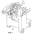
- the Fig. 1 to 5 show a schematic representation of a CNC-controlled machine 10 in particular for surface treatment of lenses L made of plastic in a rectangular Cartesian coordinate system in which the small letters x, y and z the width direction (x), the length direction (y) and the height direction (z) of the machine 10.
- the machine 10 has a machine frame 12 which limits a processing area 14.
- a processing area 14 On the in Fig. 1 left side of the processing area 14, two guide rails 16 extending in the (horizontal) width direction x parallel to each other, on an in Fig. 1 attached to the upper mounting surface 17 of the machine frame 12.
- a Y-carriage 22 is slidably mounted on the guide rails 20, which is CNC-controlled by associated CNC drive and control elements (also not shown) in both directions of a Y-axis.
- a workpiece spindle 24 is fixed, which is rotationally driven by means of an electric motor 26 in the rotational speed and the rotation angle CNC-controlled about a workpiece axis of rotation B.
- the workpiece rotation axis B is aligned with the Y axis.
- On the workpiece spindle 24, more precisely in the processing area 14 protruding end is in a conventional manner the lens block L locked on a block piece for processing in particular the prescription surface R of the lens L so mounted that it can rotate coaxially with the workpiece spindle 24.
- the workpiece spindle 24 by means of the X-stage assembly (X-slide 18, Y-slide 22) is CNC-position-controlled in an XY plane movable, which contains the workpiece axis of rotation B and to which the mounting surfaces 17th , 21 and 23 are parallel, while the lens L in rotational speed and rotation angle CNC-controlled about the workpiece axis of rotation B is rotatable.
- the milling unit 28 has a milling spindle 32 that can be driven in a speed-controlled manner by means of an electric motor 30 about a milling cutter rotation axis C, at whose end projecting into the machining area 14 a milling tool 34 is mounted.
- a milling machining operation can be performed on the lens L, which - according to the teaching of EP 0 758 571 A1 - Includes a plunge operation, in which the speed-controlled about the cutter rotation axis C rotary milling tool 34 and the rotation angle controlled about the workpiece axis of rotation B rotating lens L in each of the two axial directions X and Y are controlled in such a position relative to each other that the Cutting the milling tool 34 at least in the region of the outer edge of the lens L generate an annular recess recess before the milling tool 34 in a shaping operation along a spiral path by regulating the movement path of the spectacle lens L is guided in the X and Y axes, ie in the XY plane on the lens L from the outside inwards to remove more material.
- edge processing and the faceting of the spectacle lens L are optional, although preferably mit Signende operations in this milling process L.
- a processing of the lens blank for example, on the predetermined by the spectacle frame contour circumferential contour, while in the faceting the upper or Inner peripheral edge of the lens blank is bevelled by means of the rotary milling tool 34.
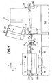
- each fast tool assembly 36, 38 an actuator 40, 42 and a respective associated carriage 44, 46 (also called “shuttle") on. While the carriage 44 of the first fast tool assembly 36 is axially movable in both directions of a fast tool axis F1 by means of the actuator 40, the carriage 46 of the second fast tool assembly 38 is in both directions by means of the actuator 42 to the first fast tool axis F1 parallel second fast tool axis F2 axially movable.
- the position or the stroke of the carriage 44, 46 independently adjustable by means of CNC.
- the fast tool axis F1, the fast tool axis F2, the Y axis, and the workpiece rotation axis B are in the same direction as seen in plan view.
- the direction of the Y axis and the workpiece rotation axis B on the one hand deviates from the direction of the Fast Tool axis F1 and the fast tool axis F2 on the other hand, which will be discussed in more detail below.
- each of the carriages 44, 46 carries, at its end projecting into the processing area 14, a turning tool 48, 50, which is fastened fixedly (as opposed to adjustable) to the respective carriage 44, 46 in a manner not shown here. such that the turning tools 48, 50 are movable in a fast-tool movement plane (X-F1 plane or X-F2 plane, respectively).
- a cutting plate 52 if necessary, releasably attached or as a coating forming a cutting edge 54 and the respective requirements, in particular specific for the material to be machined, polycrystalline diamond (PCD), CVD, natural diamond or even carbide with or without wear protection coating can exist.
- the prescription surface R of the spectacle lens L pre-machined by the milling unit 28 can be post-processed, which in turn controls the movement of the spectacle lens L in the X-axis and, if necessary.
- the fast tool arrangements 36 and 38 can be controlled such that the not involved in the turning slide moves to the slide involved in the turning in the opposite direction, so that the carriages swing virtually in opposite directions or in push-pull to mass compensation To prevent disturbing vibrations are transmitted to the machine frame 12 and to reduce these, as it is in the WO 02/06005 A1 is disclosed.
- surface qualities that are almost equivalent to the surface quality that can be achieved with conventional polishing methods can be achieved during turning.
- a peculiarity of the above-described machine 10 is, as has already been more generally mentioned above, that the fast tool assemblies 36 and 38 are mounted on a mounting surface 56 of the machine frame 12, with respect to the mounting surfaces 17, 21 and 23 for the cross table assembly (X-carriage 18, Y-slide 22) and the workpiece spindle 24 is tilted or an angle ⁇ is set so that the fast-tool movement plane (X-F1-level or X-F2-plane) with respect to the workpiece rotation axis B containing movement plane (XY plane) of the workpiece spindle 24 is tilted.
- This angle ⁇ is in the illustrated embodiment about 5 °, but may also be slightly more or less, for example, in the range of 2 ° to 10 °.
- an adjustment of the turning tool 48 by means of the fast tool assembly 36 in the F1 axis or an adjustment of the turning tool 50 by means of the fast tool assembly 38 in the F2 axis with the result that the movement of the respective Cutting edge 54 receives two components of movement, namely a component of movement in the longitudinal direction y of the machine 10 and a component of motion in the height direction z of the machine 10.
- the latter can be used, the operating point of the cutting edge 54 of the respective turning tool 48, 50 on the workpiece axis of rotation B. align the workpiece spindle 24 to compensate for height errors or deviations of the cutting edge 54 in the height direction z.
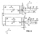
- Such a procedure is in Fig. 6 illustrated.
- a faulty height adjustment of the turning tool 48 is shown in the upper part of Fig. 6 .
- a relative delivery of workpiece spindle 24 and turning tool 48 in the longitudinal direction y takes place such that the lens L at the end of the turning (left-handed turning tool 48) has a thickness in the longitudinal direction y, the desired thickness, ie the Target end thickness d s of the lens L corresponds, a surface error remains in the form of an in Fig. 6 Excessively large illustrated pin 58 on the prescription surface R.
- This surface defect is due to the fact that the turning tool 48, more precisely its cutting edge 54 at the end of the turning operation, the workpiece rotation axis B does not "hits", but below the workpiece rotation axis B comes to a halt ( with faulty axial position y e of the workpiece spindle 24: tool 48 is too low at the end of the turning operation).
- a comparable, conical surface defect arises (not shown) when, at the end of the turning operation, the cutting edge 54 of the turning tool 48 comes to a stop above the workpiece rotation axis B (tool too high).
- Fig. 6 In the lower part of Fig. 6 is now a correct height adjustment of the turning tool 48 with respect to the workpiece axis of rotation B shown, in which on the prescription surface R of the lens L no central area error remains.
- the procedure is as follows: First, - in a known position of the cutting edge 54 of the turning tool 48 in the coordinate system of the machine 10 and known angle ⁇ of the fast tool axis F1 - calculated an axial position y k of the workpiece spindle 24 in the longitudinal direction y, in which the Operating point of the cutting edge 54 of the turning tool 48 at target end thickness d s of the lens to be processed L in the workpiece axis of rotation B containing XY plane comes to rest, ie the workpiece axis of rotation B "hits".
- the workpiece spindle 24 is brought by position-controlled axial method or in the Y-axis in the calculated axial position y k , whereupon an axial setting or holding the workpiece spindle 24 in the calculated axial position y k occurs.
- the rotationally driven spectacle lens L can be processed under position-controlled transverse feed of the workpiece spindle 24 in the X-axis and position-controlled (F1-axis) infeed of the turning tool 48 in the fast-tool movement plane, ie the X-F1 plane until the target Final thickness d s on the processed spectacle lens L is achieved.
- the workpiece rotation axis B now automatically.
- the procedure is such that the workpiece spindle 24 is not retained in the Y-axis, but in addition to the movement of the fast tool assembly 36 in the F1 axis, a geometry-generating movement of the workpiece spindle 24 in the Y-axis, more precisely the geometry generation on the Y-axis and the F1-axis is divided so that the Y-axis is responsible for the slower motion component, while the F1-axis takes over the faster motion component.
- the advantage of such a procedure is in particular that fast tool arrangements 36, 38 are used with a lower stroke and thus greater rigidity and, in addition, higher processing speeds can be achieved.
- Such a procedure then comprises the following steps: First, a spherical or even toric surface geometry is calculated which best corresponds to the desired surface geometry of the prescription surface R to be processed on the spectacle lens L ("best fit sphere” or “best fit toric surface”). , Further, as in the above-described procedure, an axial position y k of the workpiece spindle 24 is calculated at which the operating point of the cutting edge 54 of the turning tool 48 at the target final thickness d s of the lens L to be machined in the XY containing the workpiece rotation axis B. Level comes to rest.
- the rotationally driven spectacle lens L is processed, namely under position-controlled transverse feed of the workpiece spindle 24 in the X-axis, position-controlled feeding of the workpiece spindle 24 in the Y-axis along a trajectory which corresponds to the calculated spherical or toric "best fit" surface geometry, until the workpiece spindle 24 has reached the previously calculated axial position y k and simultaneous position-controlled feed of the turning tool 48 in the F1 axis or the fast tool movement plane (X-F1 plane) corresponding to deviations of the desired surface geometry of the recipe surface R to be processed from the calculated spherical or toric "best fit" surface geometry until the desired final thickness d s on the processed spectacle lens L is achieved.
- the XY plane is horizontal
- the X-F1 plane and the X-F2 plane is tilted out of the horizontal by the angle ⁇
- the conditions can basically be taken in reverse, with a horizontal X. -F1 plane or X-F2 plane and an XY plane set at an angle relative to the horizontal plane.
- the invention relates to a machine for processing optical workpieces, in particular plastic spectacle lenses, which has a workpiece spindle, by means of which the workpiece can be driven in rotation about a workpiece axis of rotation, and has a fast tool arrangement, by means of which a turning tool is provided in one Fast tool movement plane is movable, wherein the workpiece spindle and the fast tool assembly are also relatively movable in a plane containing the workpiece rotation axis.
- the fast tool movement plane is inclined with respect to the plane containing the workpiece rotation axis.
Landscapes
- Engineering & Computer Science (AREA)
- Mechanical Engineering (AREA)
- Health & Medical Sciences (AREA)
- Manufacturing & Machinery (AREA)
- Ophthalmology & Optometry (AREA)
- Turning (AREA)
- Grinding And Polishing Of Tertiary Curved Surfaces And Surfaces With Complex Shapes (AREA)
- Milling Processes (AREA)
- Eyeglasses (AREA)
- Optical Filters (AREA)
- Electrical Discharge Machining, Electrochemical Machining, And Combined Machining (AREA)
Priority Applications (3)
| Application Number | Priority Date | Filing Date | Title |
|---|---|---|---|
| DE202006005710U DE202006005710U1 (de) | 2005-05-06 | 2006-03-30 | Maschine zur Bearbeitung von optischen Werkstücken, insbesondere von Kunststoff-Brillengläsern |
| EP11002786A EP2338640B1 (de) | 2005-05-06 | 2006-03-30 | Maschine zur Bearbeitung von optischen Werkstücken, insbesondere von Kunststoff-Brillengläsern |
| DE202006020913U DE202006020913U1 (de) | 2005-05-06 | 2006-03-30 | Maschine zur Bearbeitung von optischen Werkstücken, namentlich von Kunststoff-Brillengläsern |
Applications Claiming Priority (1)
| Application Number | Priority Date | Filing Date | Title |
|---|---|---|---|
| DE102005021640A DE102005021640B4 (de) | 2005-05-06 | 2005-05-06 | Maschine zur Bearbeitung von optischen Werkstücken, insbesondere von Kunststoff-Brillengläsern |
Publications (3)
| Publication Number | Publication Date |
|---|---|
| EP1719585A2 EP1719585A2 (de) | 2006-11-08 |
| EP1719585A3 EP1719585A3 (de) | 2009-08-12 |
| EP1719585B1 true EP1719585B1 (de) | 2011-04-06 |
Family
ID=36293303
Family Applications (2)
| Application Number | Title | Priority Date | Filing Date |
|---|---|---|---|
| EP11002786A Active EP2338640B1 (de) | 2005-05-06 | 2006-03-30 | Maschine zur Bearbeitung von optischen Werkstücken, insbesondere von Kunststoff-Brillengläsern |
| EP06006637A Active EP1719585B1 (de) | 2005-05-06 | 2006-03-30 | Maschine zur Bearbeitung von optischen Werkstücken, namentlich Kunststoff-Brillengläsern |
Family Applications Before (1)
| Application Number | Title | Priority Date | Filing Date |
|---|---|---|---|
| EP11002786A Active EP2338640B1 (de) | 2005-05-06 | 2006-03-30 | Maschine zur Bearbeitung von optischen Werkstücken, insbesondere von Kunststoff-Brillengläsern |
Country Status (8)
| Country | Link |
|---|---|
| US (1) | US7597033B2 (ja) |
| EP (2) | EP2338640B1 (ja) |
| JP (1) | JP5198739B2 (ja) |
| CN (1) | CN100562387C (ja) |
| AT (1) | ATE504392T1 (ja) |
| BR (1) | BRPI0601577B1 (ja) |
| DE (4) | DE102005021640B4 (ja) |
| HK (1) | HK1093708A1 (ja) |
Families Citing this family (38)
| Publication number | Priority date | Publication date | Assignee | Title |
|---|---|---|---|---|
| DE102004037454A1 (de) * | 2004-08-02 | 2006-02-23 | Carl Zeiss Ag | Verfahren zur Bearbeitung von Oberflächen von Werkstücken |
| DE102005052314A1 (de) * | 2005-11-01 | 2007-05-03 | Satisloh Gmbh | Fast-Tool-Anordnung, insbesondere für Drehmaschinen zur Bearbeitung von optischen Werkstücken |
| DE102006026524A1 (de) * | 2006-06-06 | 2007-12-13 | Satisloh Ag | Maschine zur Bearbeitung von optischen Werkstücken, insbesondere von Kunststoff-Brillengläsern |
| JP4692444B2 (ja) * | 2006-09-07 | 2011-06-01 | 村田機械株式会社 | 旋盤 |
| EP1916060B1 (de) * | 2006-10-26 | 2009-05-06 | Satisloh AG | Maschine zur Bearbeitung von optischen Werkstücken, insbesondere von Kunststoff-Brillengläsern |
| DE102007031703A1 (de) * | 2007-07-06 | 2009-01-08 | Satisloh Gmbh | Maschine zur Bearbeitung von optischen Werkstücken, insbesondere von Kunststoff-Brillengläsern |
| WO2009006919A1 (en) * | 2007-07-09 | 2009-01-15 | Carl Zeiss Smt Ag | Method of measuring a deviation an optical surface from a target shape |
| CN101821663B (zh) | 2007-10-10 | 2012-02-08 | Hoya株式会社 | 渐进多焦镜片的制造方法和渐进多焦镜片 |
| US20090164008A1 (en) * | 2007-12-21 | 2009-06-25 | Xin Hong | Lens surface with combined diffractive, toric, and aspheric components |
| EP2093018B2 (en) | 2008-02-25 | 2017-11-01 | Satisloh AG | Block piece for holding an optical workpiece, in particular a spectacle lens, for processing thereof, and method for manufacturing spectacle lenses according to a prescription |
| EP2138271B1 (en) | 2008-06-26 | 2011-08-03 | Satisloh AG | Method for manufacturing spectacle lenses according to a prescription |
| TWI533966B (zh) * | 2008-09-18 | 2016-05-21 | Flir系統貿易比利時公司 | 切削材料之系統及方法 |
| DE102009011194A1 (de) | 2009-03-04 | 2010-09-09 | Schneider Gmbh & Co. Kg | Drehmaschine zum Herstellen von Brillengläsern aus Kunststoff |
| FR2954196B1 (fr) * | 2009-12-21 | 2012-01-20 | Essilor Int | Procede d'usinage pour tournage d'une face d'un verre de lunettes |
| FR2979558B1 (fr) * | 2011-09-01 | 2013-10-04 | Essilor Int | Procede de surfacage d'une surface d'un verre de lunettes |
| JP2014531332A (ja) * | 2011-09-22 | 2014-11-27 | アクティエボラゲット・エスコーエッフ | 機械加工操作のインプロセス補償及び機械装置 |
| DE102012004547A1 (de) | 2012-03-10 | 2013-09-12 | Satisloh Ag | Vorrichtung zur Feinbearbeitung von optisch wirksamen Flächen an insbesondere Brillengläsern und flexible Fertigungszelle umfassend eine solche Vorrichtung |
| DE102012004543A1 (de) | 2012-03-11 | 2013-09-12 | Satisloh Ag | Maschine zur Bearbeitung von optischen Werkstücken, insbesondere von Kunststoff-Brillengläsern |
| LU92190B1 (en) | 2013-05-06 | 2014-11-07 | Satisloh Gmbh | Multi part blocking piece |
| LU92191B1 (en) | 2013-05-06 | 2014-11-07 | Satisloh Gmbh | Multimaterial block piece |
| EP2813305B1 (de) | 2013-06-12 | 2016-03-23 | Satisloh AG | Fast-Tool-Drehmaschine |
| JP5916802B2 (ja) * | 2014-06-27 | 2016-05-11 | 株式会社ソディック | 旋削加工装置の工具送り装置 |
| EP2963458B1 (en) | 2014-07-05 | 2022-02-02 | Satisloh AG | Lens blank having a temporary grip coating for a method for manufacturing spectacle lenses according to a prescription |
| DE102014113421B4 (de) | 2014-09-17 | 2016-07-28 | Optotech Optikmaschinen Gmbh | Simultan-Drehmaschine für die Brillenglasfertigung |
| EP3009230B1 (en) | 2014-10-15 | 2021-01-13 | Satisloh AG | Blocking unit for a block piece for a spectacle lens and process of curing |
| JP2016153149A (ja) * | 2015-02-20 | 2016-08-25 | ファナック株式会社 | 旋削工具ホルダ装着ユニットを備えた工作機械 |
| DE102015102900A1 (de) | 2015-02-27 | 2016-09-01 | Optotech Optikmaschinen Gmbh | Simultan-Drehmaschine für die Brillenglasfertigung |
| DE102015102899B4 (de) | 2015-02-27 | 2018-02-01 | Optotech Optikmaschinen Gmbh | Fräsvorrichtung für die Brillenglasfertigung mit zwei Frässtationen |
| DE102015009973A1 (de) | 2015-07-31 | 2017-02-02 | Satisloh Ag | Verfahren zur Bearbeitung von optischen Werkstücken, insbesondere Brillenlinsen aus Kunststoff |
| GB2569307B (en) * | 2017-12-12 | 2022-06-29 | Fives Landis Ltd | Machine tools and methods of operation thereof |
| EP3542956A1 (en) | 2018-03-23 | 2019-09-25 | Carl Zeiss Vision International GmbH | Method for manufacturing spectacle lenses according to a prescription |
| US11618122B1 (en) * | 2019-03-08 | 2023-04-04 | Raytheon Company | Methods and apparatus for generating free-form optical components |
| GB2589874B (en) * | 2019-12-10 | 2024-05-01 | Fives Landis Ltd | Machine tools and methods of operation thereof |
| CN112643061B (zh) * | 2020-12-04 | 2024-05-10 | 中国科学院苏州生物医学工程技术研究所 | 一种物镜加工装置 |
| DE102021004831A1 (de) | 2021-09-24 | 2023-03-30 | Satisloh Ag | Verfahren zur spanenden bearbeitung von optischen werkstücken, insbesondere brillenlinsen aus kunststoff |
| DE102021005202A1 (de) | 2021-10-19 | 2023-04-20 | Satisloh Ag | Aufnahme für die Bearbeitung von optischen Werkstücken, insbesondere Brillenlinsen |
| CN114633030B (zh) * | 2022-02-24 | 2024-03-26 | 江门金鸿桦烨电子科技有限公司 | 一种镜片加工方法 |
| KR102588804B1 (ko) * | 2023-03-07 | 2023-10-16 | 주식회사 에스피오엠 | 렌즈 하우징 가공 장치 |
Family Cites Families (34)
| Publication number | Priority date | Publication date | Assignee | Title |
|---|---|---|---|---|
| DE494264C (de) | 1929-04-24 | 1930-03-20 | Heinrich Lanvermeyer | Support mit Hoeheneinstellung des Drehstahles |
| FR1212288A (fr) * | 1958-10-02 | 1960-03-23 | Ernault Batignolles H | Dispositif d'inversion de sens pour mécanisme de machine-outil d'avance-recul à stationnement avant recul |
| US3181382A (en) * | 1959-06-24 | 1965-05-04 | Ernest J Berlo | Machine tool |
| US4333368A (en) * | 1980-07-15 | 1982-06-08 | Kollmorgen Technologies Corporation | Method and apparatus for generating aspherical surfaces of revolution |
| JPS58171244A (ja) * | 1982-03-29 | 1983-10-07 | Mitsubishi Heavy Ind Ltd | 数値制御旋盤の位置補正装置 |
| CH666647A5 (de) * | 1985-08-10 | 1988-08-15 | Wyler Ag | Spanabhebende werkzeugmaschine. |
| DE3600231A1 (de) * | 1986-01-07 | 1987-07-09 | Heyligenstaedt & Co | Numerisch gesteuerte drehmaschine |
| DE3618938A1 (de) * | 1986-06-09 | 1987-12-10 | Ravensburg Maschf | Drehmaschine |
| US5168609A (en) * | 1987-12-24 | 1992-12-08 | Yamazaki Mazik Corp. | Workpiece support for a turret on a opposed spindle lathe |
| JP2897961B2 (ja) * | 1990-05-02 | 1999-05-31 | ヤマザキマザック株式会社 | 工作機械における芯高調整機構 |
| DE4105768A1 (de) * | 1991-02-23 | 1992-08-27 | Magdeburg Werkzeugmasch | Drehmaschine |
| ES2070399T3 (es) * | 1991-10-19 | 1995-06-01 | Index Werke Kg Hahn & Tessky | Torno. |
| JPH05200601A (ja) * | 1992-01-24 | 1993-08-10 | Takizawa Tekkosho:Kk | 工作機械 |
| JP2729248B2 (ja) * | 1992-02-25 | 1998-03-18 | オークマ株式会社 | 非真円形状加工旋盤 |
| DE4227268A1 (de) * | 1992-08-18 | 1994-02-24 | Heidelberger Druckmasch Ag | Werkzeughalter |
| US5245896A (en) * | 1992-08-19 | 1993-09-21 | Kennametal Inc. | Quick-change tool holder with center height adjustment mechanism |
| US5765456A (en) * | 1993-09-11 | 1998-06-16 | Index-Werke Gmbh & Co. Hahn & Tessky | Process for the machining of a workpiece on a CNC automatic lathe as well as a CNC automatic lathe |
| DE19529786C1 (de) | 1995-08-12 | 1997-03-06 | Loh Optikmaschinen Ag | Verfahren und Werkzeug zur Erzeugung einer konkaven Oberfläche an einem Brillenglasrohling |
| JP3938213B2 (ja) * | 1995-10-14 | 2007-06-27 | カール ツァイス ヴィジオーン ゲーエムベーハー | 光学的表面または光学的表面を製造するための型枠の加工方法およびこの方法を実施するための加工機 |
| JP2788231B2 (ja) * | 1996-09-04 | 1998-08-20 | 川崎重工業株式会社 | 長尺バー材加工装置とその加工方法 |
| DE19653233A1 (de) * | 1996-12-20 | 1998-07-02 | Schneider Gmbh & Co Kg | Hochgeschwindigkeits-Drehmaschine zum Herstellen optisch wirksamer Oberflächen |
| JP4322324B2 (ja) * | 1997-04-17 | 2009-08-26 | ノバルティス アクチエンゲゼルシャフト | 旋盤装置及び方法 |
| US6038549A (en) * | 1997-12-22 | 2000-03-14 | Motorola Inc | Portable 1-way wireless financial messaging unit |
| US6237452B1 (en) | 1997-12-29 | 2001-05-29 | Massachusetts Institute Of Technology | Precision high speed turning machine |
| JP2000107903A (ja) * | 1998-10-06 | 2000-04-18 | Murata Mach Ltd | 旋 盤 |
| SE513774C2 (sv) * | 1999-03-16 | 2000-11-06 | Quintax Machine Tools Ab | Förfarande för svarvning, objekt framställt genom förfarandet och svarv för genomförande av förfarandet |
| CA2313830A1 (en) * | 2000-07-13 | 2002-01-13 | Micro Optics Design Corporation | Single point diamond turning lathe with vibration cancelling feature |
| JP2002273602A (ja) * | 2001-03-21 | 2002-09-25 | Big Alpha Co Ltd | 自動工具交換装置付旋盤 |
| DE10143848C2 (de) * | 2001-09-06 | 2003-10-02 | Loh Optikmaschinen Ag | Verfahren und Vorrichtung zur Flächenbearbeitung von Werkstücken aus nicht-sprödharten Materialien in der Optikfertigung sowie Werkzeug dafür |
| DE502004012401D1 (de) * | 2003-03-11 | 2011-05-26 | Carl Zeiss Vision Gmbh | Verfahren und vorrichtung zur fertigung von brillengläsern und anderen formkörpern mit optisch aktiven oberflächen |
| JP4234514B2 (ja) * | 2003-07-09 | 2009-03-04 | 株式会社森精機製作所 | Nc旋盤 |
| JP4171363B2 (ja) * | 2003-07-11 | 2008-10-22 | 西部電機株式会社 | 工作物を任意の曲面に切削加工する高速曲面加工方法 |
| JP2005125482A (ja) * | 2003-10-03 | 2005-05-19 | Tsugami Corp | 旋盤 |
| JP4632344B2 (ja) * | 2003-12-18 | 2011-02-16 | 株式会社森精機製作所 | ボーリングバーマガジンを有する工作機械 |
-
2005
- 2005-05-06 DE DE102005021640A patent/DE102005021640B4/de active Active
-
2006
- 2006-03-30 DE DE202006021076U patent/DE202006021076U1/de not_active Expired - Lifetime
- 2006-03-30 EP EP11002786A patent/EP2338640B1/de active Active
- 2006-03-30 DE DE202006020913U patent/DE202006020913U1/de not_active Expired - Lifetime
- 2006-03-30 EP EP06006637A patent/EP1719585B1/de active Active
- 2006-03-30 AT AT06006637T patent/ATE504392T1/de active
- 2006-03-30 DE DE502006009236T patent/DE502006009236D1/de active Active
- 2006-04-27 CN CNB2006100799062A patent/CN100562387C/zh active Active
- 2006-05-01 US US11/415,330 patent/US7597033B2/en active Active
- 2006-05-02 JP JP2006128276A patent/JP5198739B2/ja active Active
- 2006-05-05 BR BRPI0601577-8A patent/BRPI0601577B1/pt active IP Right Grant
-
2007
- 2007-01-25 HK HK07100878.0A patent/HK1093708A1/xx unknown
Also Published As
| Publication number | Publication date |
|---|---|
| EP2338640A1 (de) | 2011-06-29 |
| US20060260447A1 (en) | 2006-11-23 |
| CN1857835A (zh) | 2006-11-08 |
| EP1719585A3 (de) | 2009-08-12 |
| DE202006021076U1 (de) | 2012-04-16 |
| DE202006020913U1 (de) | 2010-10-28 |
| CN100562387C (zh) | 2009-11-25 |
| BRPI0601577A (pt) | 2007-07-17 |
| DE502006009236D1 (de) | 2011-05-19 |
| HK1093708A1 (en) | 2007-03-09 |
| JP5198739B2 (ja) | 2013-05-15 |
| DE102005021640B4 (de) | 2007-08-09 |
| US7597033B2 (en) | 2009-10-06 |
| JP2006312233A (ja) | 2006-11-16 |
| ATE504392T1 (de) | 2011-04-15 |
| DE102005021640A1 (de) | 2006-11-09 |
| BRPI0601577B1 (pt) | 2019-07-02 |
| EP1719585A2 (de) | 2006-11-08 |
| EP2338640B1 (de) | 2012-05-23 |
Similar Documents
| Publication | Publication Date | Title |
|---|---|---|
| EP1719585B1 (de) | Maschine zur Bearbeitung von optischen Werkstücken, namentlich Kunststoff-Brillengläsern | |
| EP1291106B1 (de) | Verfahren und Vorrichtung zur Flächenbearbeitung von Werkstücken aus nicht-sprödharten Materialien in der Optikfertigung sowie Werkzeug dafür | |
| EP1719582B1 (de) | Hochleistungs-Fräs-und Drehmaschine sowie Verfahren zur Bearbeitung von insbesondere Brillengläsern | |
| EP1864753B1 (de) | Maschine zur Bearbeitung von optischen Werkstücken, insbesondere von Kunststoff-Brillengläsern | |
| EP3463746B1 (de) | Maschine zur bearbeitung von optisch wirksamen flächen | |
| EP0685298B2 (de) | Verfahren und Vorrichtung zum Herstellen asphärischer Linsenoberflächen | |
| EP2823924A2 (de) | Doppelabrichter | |
| EP3012056A1 (de) | Verfahren und vorrichtung zum anfasen und entgraten verzahnter werkstücke | |
| EP0807491A1 (de) | Halterung für optische Linsen und Verfahren zum Polieren von Linsen | |
| DE19616526A1 (de) | Maschine zur materialabtragenden Bearbeitung optischer Werkstoffe für die Herstellung von Optikteilen | |
| CH697397B1 (de) | Verfahren und Vorrichtung zum Schleifen eines Profils eines Werkstücks. | |
| EP1422005B1 (de) | Verfahren und Vorrichtung zur Randbearbeitung einer optischen Linse aus Kunststoff | |
| DE19751750B4 (de) | Verfahren und Vorrichtung zum Herstellen von polierbaren, optischen Linsen aus Linsenrohlingen | |
| EP2308627A1 (de) | Hartfeinbearbeitungsmaschine zum Hartfeinbearbeiten eines Werkstuecks | |
| DE102004037454A1 (de) | Verfahren zur Bearbeitung von Oberflächen von Werkstücken | |
| EP0868242B1 (de) | Verfahren und vorrichtung zum drehfräsen | |
| EP2470319B1 (de) | Verfahren zur spanenden drehbearbeitung und drehbearbeitungsvorrichtung | |
| EP0991497B1 (de) | Verfahren und vorrichtung zur spanenden bearbeitung unrunder innen- und aussenkonturen | |
| EP0937542A1 (de) | Verfahren zum Polieren optischer Linsen und Mehrspindel-Poliermaschine mit verschiedenen Polierwerkzeugen zur Durchführung des Verfahrens | |
| EP0841116A2 (de) | Verfahren zum Bearbeiten von rotationssymmetrischen Werkstückflächen sowie Werkzeug zur Durchführung eines solchen Verfahrens | |
| DE102017129651A1 (de) | Verfahren zur Verzahnbearbeitung eines Werkstücks | |
| DE202006005710U1 (de) | Maschine zur Bearbeitung von optischen Werkstücken, insbesondere von Kunststoff-Brillengläsern | |
| EP3330026B1 (de) | Drehräumwerkzeug | |
| DE3611103A1 (de) | Schleifmaschine | |
| WO1984000909A1 (en) | Automatic multi-spindle lathe |
Legal Events
| Date | Code | Title | Description |
|---|---|---|---|
| PUAI | Public reference made under article 153(3) epc to a published international application that has entered the european phase |
Free format text: ORIGINAL CODE: 0009012 |
|
| AK | Designated contracting states |
Kind code of ref document: A2 Designated state(s): AT BE BG CH CY CZ DE DK EE ES FI FR GB GR HU IE IS IT LI LT LU LV MC NL PL PT RO SE SI SK TR |
|
| AX | Request for extension of the european patent |
Extension state: AL BA HR MK YU |
|
| PUAL | Search report despatched |
Free format text: ORIGINAL CODE: 0009013 |
|
| AK | Designated contracting states |
Kind code of ref document: A3 Designated state(s): AT BE BG CH CY CZ DE DK EE ES FI FR GB GR HU IE IS IT LI LT LU LV MC NL PL PT RO SE SI SK TR |
|
| AX | Request for extension of the european patent |
Extension state: AL BA HR MK YU |
|
| RIC1 | Information provided on ipc code assigned before grant |
Ipc: B24B 41/00 20060101ALI20090703BHEP Ipc: B24B 13/04 20060101ALI20090703BHEP Ipc: B23Q 1/60 20060101ALI20090703BHEP Ipc: B24B 13/06 20060101AFI20060518BHEP Ipc: B24B 47/20 20060101ALI20090703BHEP Ipc: B24B 47/22 20060101ALI20090703BHEP |
|
| 17P | Request for examination filed |
Effective date: 20090717 |
|
| AKX | Designation fees paid |
Designated state(s): AT BE BG CH CY CZ DE DK EE ES FI FR GB GR HU IE IS IT LI LT LU LV MC NL PL PT RO SE SI SK TR |
|
| RTI1 | Title (correction) |
Free format text: MACHINE FOR GRINDING OPTICAL WORKPIECES, ESPECIALLY PLASTIC SPECTACLE GLASSES |
|
| GRAP | Despatch of communication of intention to grant a patent |
Free format text: ORIGINAL CODE: EPIDOSNIGR1 |
|
| GRAS | Grant fee paid |
Free format text: ORIGINAL CODE: EPIDOSNIGR3 |
|
| RIN1 | Information on inventor provided before grant (corrected) |
Inventor name: SAVOIE, MARC Inventor name: MCPHERSON, EDWARD |
|
| GRAA | (expected) grant |
Free format text: ORIGINAL CODE: 0009210 |
|
| AK | Designated contracting states |
Kind code of ref document: B1 Designated state(s): AT BE BG CH CY CZ DE DK EE ES FI FR GB GR HU IE IS IT LI LT LU LV MC NL PL PT RO SE SI SK TR |
|
| REG | Reference to a national code |
Ref country code: GB Ref legal event code: FG4D Free format text: NOT ENGLISH |
|
| REG | Reference to a national code |
Ref country code: CH Ref legal event code: EP |
|
| REG | Reference to a national code |
Ref country code: IE Ref legal event code: FG4D |
|
| REG | Reference to a national code |
Ref country code: CH Ref legal event code: NV Representative=s name: KEMENY AG PATENTANWALTBUERO |
|
| REF | Corresponds to: |
Ref document number: 502006009236 Country of ref document: DE Date of ref document: 20110519 Kind code of ref document: P |
|
| REG | Reference to a national code |
Ref country code: DE Ref legal event code: R096 Ref document number: 502006009236 Country of ref document: DE Effective date: 20110519 |
|
| REG | Reference to a national code |
Ref country code: NL Ref legal event code: T3 |
|
| PG25 | Lapsed in a contracting state [announced via postgrant information from national office to epo] |
Ref country code: SI Free format text: LAPSE BECAUSE OF FAILURE TO SUBMIT A TRANSLATION OF THE DESCRIPTION OR TO PAY THE FEE WITHIN THE PRESCRIBED TIME-LIMIT Effective date: 20110406 |
|
| LTIE | Lt: invalidation of european patent or patent extension |
Effective date: 20110406 |
|
| REG | Reference to a national code |
Ref country code: IE Ref legal event code: FD4D |
|
| PG25 | Lapsed in a contracting state [announced via postgrant information from national office to epo] |
Ref country code: LT Free format text: LAPSE BECAUSE OF FAILURE TO SUBMIT A TRANSLATION OF THE DESCRIPTION OR TO PAY THE FEE WITHIN THE PRESCRIBED TIME-LIMIT Effective date: 20110406 Ref country code: PT Free format text: LAPSE BECAUSE OF FAILURE TO SUBMIT A TRANSLATION OF THE DESCRIPTION OR TO PAY THE FEE WITHIN THE PRESCRIBED TIME-LIMIT Effective date: 20110808 Ref country code: SE Free format text: LAPSE BECAUSE OF FAILURE TO SUBMIT A TRANSLATION OF THE DESCRIPTION OR TO PAY THE FEE WITHIN THE PRESCRIBED TIME-LIMIT Effective date: 20110406 |
|
| PG25 | Lapsed in a contracting state [announced via postgrant information from national office to epo] |
Ref country code: LV Free format text: LAPSE BECAUSE OF FAILURE TO SUBMIT A TRANSLATION OF THE DESCRIPTION OR TO PAY THE FEE WITHIN THE PRESCRIBED TIME-LIMIT Effective date: 20110406 Ref country code: IS Free format text: LAPSE BECAUSE OF FAILURE TO SUBMIT A TRANSLATION OF THE DESCRIPTION OR TO PAY THE FEE WITHIN THE PRESCRIBED TIME-LIMIT Effective date: 20110806 Ref country code: GR Free format text: LAPSE BECAUSE OF FAILURE TO SUBMIT A TRANSLATION OF THE DESCRIPTION OR TO PAY THE FEE WITHIN THE PRESCRIBED TIME-LIMIT Effective date: 20110707 Ref country code: CY Free format text: LAPSE BECAUSE OF FAILURE TO SUBMIT A TRANSLATION OF THE DESCRIPTION OR TO PAY THE FEE WITHIN THE PRESCRIBED TIME-LIMIT Effective date: 20110406 Ref country code: FI Free format text: LAPSE BECAUSE OF FAILURE TO SUBMIT A TRANSLATION OF THE DESCRIPTION OR TO PAY THE FEE WITHIN THE PRESCRIBED TIME-LIMIT Effective date: 20110406 Ref country code: ES Free format text: LAPSE BECAUSE OF FAILURE TO SUBMIT A TRANSLATION OF THE DESCRIPTION OR TO PAY THE FEE WITHIN THE PRESCRIBED TIME-LIMIT Effective date: 20110717 |
|
| PG25 | Lapsed in a contracting state [announced via postgrant information from national office to epo] |
Ref country code: CZ Free format text: LAPSE BECAUSE OF FAILURE TO SUBMIT A TRANSLATION OF THE DESCRIPTION OR TO PAY THE FEE WITHIN THE PRESCRIBED TIME-LIMIT Effective date: 20110406 Ref country code: EE Free format text: LAPSE BECAUSE OF FAILURE TO SUBMIT A TRANSLATION OF THE DESCRIPTION OR TO PAY THE FEE WITHIN THE PRESCRIBED TIME-LIMIT Effective date: 20110406 Ref country code: IE Free format text: LAPSE BECAUSE OF FAILURE TO SUBMIT A TRANSLATION OF THE DESCRIPTION OR TO PAY THE FEE WITHIN THE PRESCRIBED TIME-LIMIT Effective date: 20110406 |
|
| PLBE | No opposition filed within time limit |
Free format text: ORIGINAL CODE: 0009261 |
|
| STAA | Information on the status of an ep patent application or granted ep patent |
Free format text: STATUS: NO OPPOSITION FILED WITHIN TIME LIMIT |
|
| PG25 | Lapsed in a contracting state [announced via postgrant information from national office to epo] |
Ref country code: SK Free format text: LAPSE BECAUSE OF FAILURE TO SUBMIT A TRANSLATION OF THE DESCRIPTION OR TO PAY THE FEE WITHIN THE PRESCRIBED TIME-LIMIT Effective date: 20110406 Ref country code: DK Free format text: LAPSE BECAUSE OF FAILURE TO SUBMIT A TRANSLATION OF THE DESCRIPTION OR TO PAY THE FEE WITHIN THE PRESCRIBED TIME-LIMIT Effective date: 20110406 Ref country code: RO Free format text: LAPSE BECAUSE OF FAILURE TO SUBMIT A TRANSLATION OF THE DESCRIPTION OR TO PAY THE FEE WITHIN THE PRESCRIBED TIME-LIMIT Effective date: 20110406 Ref country code: PL Free format text: LAPSE BECAUSE OF FAILURE TO SUBMIT A TRANSLATION OF THE DESCRIPTION OR TO PAY THE FEE WITHIN THE PRESCRIBED TIME-LIMIT Effective date: 20110406 |
|
| REG | Reference to a national code |
Ref country code: CH Ref legal event code: PFA Owner name: SATISLOH GMBH Free format text: SATISLOH GMBH#WILHELM-LOH-STRASSE 2-4#35578 WETZLAR (DE) -TRANSFER TO- SATISLOH GMBH#WILHELM-LOH-STRASSE 2-4#35578 WETZLAR (DE) |
|
| 26N | No opposition filed |
Effective date: 20120110 |
|
| REG | Reference to a national code |
Ref country code: DE Ref legal event code: R097 Ref document number: 502006009236 Country of ref document: DE Effective date: 20120110 |
|
| BERE | Be: lapsed |
Owner name: SATISLOH G.M.B.H. Effective date: 20120331 |
|
| PG25 | Lapsed in a contracting state [announced via postgrant information from national office to epo] |
Ref country code: MC Free format text: LAPSE BECAUSE OF NON-PAYMENT OF DUE FEES Effective date: 20120331 |
|
| PG25 | Lapsed in a contracting state [announced via postgrant information from national office to epo] |
Ref country code: BE Free format text: LAPSE BECAUSE OF NON-PAYMENT OF DUE FEES Effective date: 20120331 |
|
| REG | Reference to a national code |
Ref country code: AT Ref legal event code: MM01 Ref document number: 504392 Country of ref document: AT Kind code of ref document: T Effective date: 20120330 |
|
| PG25 | Lapsed in a contracting state [announced via postgrant information from national office to epo] |
Ref country code: BG Free format text: LAPSE BECAUSE OF FAILURE TO SUBMIT A TRANSLATION OF THE DESCRIPTION OR TO PAY THE FEE WITHIN THE PRESCRIBED TIME-LIMIT Effective date: 20110706 |
|
| PG25 | Lapsed in a contracting state [announced via postgrant information from national office to epo] |
Ref country code: AT Free format text: LAPSE BECAUSE OF NON-PAYMENT OF DUE FEES Effective date: 20120330 |
|
| PG25 | Lapsed in a contracting state [announced via postgrant information from national office to epo] |
Ref country code: TR Free format text: LAPSE BECAUSE OF FAILURE TO SUBMIT A TRANSLATION OF THE DESCRIPTION OR TO PAY THE FEE WITHIN THE PRESCRIBED TIME-LIMIT Effective date: 20110406 |
|
| PG25 | Lapsed in a contracting state [announced via postgrant information from national office to epo] |
Ref country code: LU Free format text: LAPSE BECAUSE OF NON-PAYMENT OF DUE FEES Effective date: 20120330 |
|
| PG25 | Lapsed in a contracting state [announced via postgrant information from national office to epo] |
Ref country code: HU Free format text: LAPSE BECAUSE OF FAILURE TO SUBMIT A TRANSLATION OF THE DESCRIPTION OR TO PAY THE FEE WITHIN THE PRESCRIBED TIME-LIMIT Effective date: 20060330 |
|
| REG | Reference to a national code |
Ref country code: FR Ref legal event code: PLFP Year of fee payment: 11 |
|
| REG | Reference to a national code |
Ref country code: FR Ref legal event code: PLFP Year of fee payment: 12 |
|
| REG | Reference to a national code |
Ref country code: FR Ref legal event code: PLFP Year of fee payment: 13 |
|
| REG | Reference to a national code |
Ref country code: CH Ref legal event code: PFUS Owner name: SATISLOH GMBH, DE Free format text: FORMER OWNER: SATISLOH GMBH, DE |
|
| PGFP | Annual fee paid to national office [announced via postgrant information from national office to epo] |
Ref country code: FR Payment date: 20230327 Year of fee payment: 18 |
|
| PGFP | Annual fee paid to national office [announced via postgrant information from national office to epo] |
Ref country code: IT Payment date: 20230321 Year of fee payment: 18 |
|
| P01 | Opt-out of the competence of the unified patent court (upc) registered |
Effective date: 20230525 |
|
| PGFP | Annual fee paid to national office [announced via postgrant information from national office to epo] |
Ref country code: CH Payment date: 20230402 Year of fee payment: 18 |
|
| PGFP | Annual fee paid to national office [announced via postgrant information from national office to epo] |
Ref country code: NL Payment date: 20240326 Year of fee payment: 19 |
|
| PGFP | Annual fee paid to national office [announced via postgrant information from national office to epo] |
Ref country code: DE Payment date: 20240327 Year of fee payment: 19 Ref country code: GB Payment date: 20240327 Year of fee payment: 19 |