EP1718392B1 - Sechoir a air a double cartouche presentant un separateur d'huile et des vannes facilement remplacables - Google Patents
Sechoir a air a double cartouche presentant un separateur d'huile et des vannes facilement remplacables Download PDFInfo
- Publication number
- EP1718392B1 EP1718392B1 EP05712921.5A EP05712921A EP1718392B1 EP 1718392 B1 EP1718392 B1 EP 1718392B1 EP 05712921 A EP05712921 A EP 05712921A EP 1718392 B1 EP1718392 B1 EP 1718392B1
- Authority
- EP
- European Patent Office
- Prior art keywords
- air
- valve
- dryer system
- center section
- air dryer
- Prior art date
- Legal status (The legal status is an assumption and is not a legal conclusion. Google has not performed a legal analysis and makes no representation as to the accuracy of the status listed.)
- Not-in-force
Links
Images


Classifications
-
- B—PERFORMING OPERATIONS; TRANSPORTING
- B01—PHYSICAL OR CHEMICAL PROCESSES OR APPARATUS IN GENERAL
- B01D—SEPARATION
- B01D53/00—Separation of gases or vapours; Recovering vapours of volatile solvents from gases; Chemical or biological purification of waste gases, e.g. engine exhaust gases, smoke, fumes, flue gases, aerosols
- B01D53/02—Separation of gases or vapours; Recovering vapours of volatile solvents from gases; Chemical or biological purification of waste gases, e.g. engine exhaust gases, smoke, fumes, flue gases, aerosols by adsorption, e.g. preparative gas chromatography
- B01D53/04—Separation of gases or vapours; Recovering vapours of volatile solvents from gases; Chemical or biological purification of waste gases, e.g. engine exhaust gases, smoke, fumes, flue gases, aerosols by adsorption, e.g. preparative gas chromatography with stationary adsorbents
- B01D53/0407—Constructional details of adsorbing systems
- B01D53/0415—Beds in cartridges
-
- B—PERFORMING OPERATIONS; TRANSPORTING
- B01—PHYSICAL OR CHEMICAL PROCESSES OR APPARATUS IN GENERAL
- B01D—SEPARATION
- B01D45/00—Separating dispersed particles from gases or vapours by gravity, inertia, or centrifugal forces
- B01D45/04—Separating dispersed particles from gases or vapours by gravity, inertia, or centrifugal forces by utilising inertia
- B01D45/08—Separating dispersed particles from gases or vapours by gravity, inertia, or centrifugal forces by utilising inertia by impingement against baffle separators
-
- B—PERFORMING OPERATIONS; TRANSPORTING
- B01—PHYSICAL OR CHEMICAL PROCESSES OR APPARATUS IN GENERAL
- B01D—SEPARATION
- B01D46/00—Filters or filtering processes specially modified for separating dispersed particles from gases or vapours
- B01D46/0027—Filters or filtering processes specially modified for separating dispersed particles from gases or vapours with additional separating or treating functions
- B01D46/003—Filters or filtering processes specially modified for separating dispersed particles from gases or vapours with additional separating or treating functions including coalescing means for the separation of liquid
-
- B—PERFORMING OPERATIONS; TRANSPORTING
- B01—PHYSICAL OR CHEMICAL PROCESSES OR APPARATUS IN GENERAL
- B01D—SEPARATION
- B01D53/00—Separation of gases or vapours; Recovering vapours of volatile solvents from gases; Chemical or biological purification of waste gases, e.g. engine exhaust gases, smoke, fumes, flue gases, aerosols
- B01D53/26—Drying gases or vapours
- B01D53/261—Drying gases or vapours by adsorption
-
- F—MECHANICAL ENGINEERING; LIGHTING; HEATING; WEAPONS; BLASTING
- F26—DRYING
- F26B—DRYING SOLID MATERIALS OR OBJECTS BY REMOVING LIQUID THEREFROM
- F26B21/00—Arrangements or duct systems, e.g. in combination with pallet boxes, for supplying and controlling air or gases for drying solid materials or objects
-
- B—PERFORMING OPERATIONS; TRANSPORTING
- B01—PHYSICAL OR CHEMICAL PROCESSES OR APPARATUS IN GENERAL
- B01D—SEPARATION
- B01D2257/00—Components to be removed
- B01D2257/70—Organic compounds not provided for in groups B01D2257/00 - B01D2257/602
- B01D2257/702—Hydrocarbons
-
- B—PERFORMING OPERATIONS; TRANSPORTING
- B01—PHYSICAL OR CHEMICAL PROCESSES OR APPARATUS IN GENERAL
- B01D—SEPARATION
- B01D2257/00—Components to be removed
- B01D2257/80—Water
-
- B—PERFORMING OPERATIONS; TRANSPORTING
- B01—PHYSICAL OR CHEMICAL PROCESSES OR APPARATUS IN GENERAL
- B01D—SEPARATION
- B01D2259/00—Type of treatment
- B01D2259/40—Further details for adsorption processes and devices
- B01D2259/40003—Methods relating to valve switching
-
- B—PERFORMING OPERATIONS; TRANSPORTING
- B01—PHYSICAL OR CHEMICAL PROCESSES OR APPARATUS IN GENERAL
- B01D—SEPARATION
- B01D2259/00—Type of treatment
- B01D2259/40—Further details for adsorption processes and devices
- B01D2259/40083—Regeneration of adsorbents in processes other than pressure or temperature swing adsorption
- B01D2259/40086—Regeneration of adsorbents in processes other than pressure or temperature swing adsorption by using a purge gas
-
- B—PERFORMING OPERATIONS; TRANSPORTING
- B01—PHYSICAL OR CHEMICAL PROCESSES OR APPARATUS IN GENERAL
- B01D—SEPARATION
- B01D2259/00—Type of treatment
- B01D2259/40—Further details for adsorption processes and devices
- B01D2259/402—Further details for adsorption processes and devices using two beds
-
- B—PERFORMING OPERATIONS; TRANSPORTING
- B01—PHYSICAL OR CHEMICAL PROCESSES OR APPARATUS IN GENERAL
- B01D—SEPARATION
- B01D2259/00—Type of treatment
- B01D2259/45—Gas separation or purification devices adapted for specific applications
- B01D2259/4566—Gas separation or purification devices adapted for specific applications for use in transportation means
-
- Y—GENERAL TAGGING OF NEW TECHNOLOGICAL DEVELOPMENTS; GENERAL TAGGING OF CROSS-SECTIONAL TECHNOLOGIES SPANNING OVER SEVERAL SECTIONS OF THE IPC; TECHNICAL SUBJECTS COVERED BY FORMER USPC CROSS-REFERENCE ART COLLECTIONS [XRACs] AND DIGESTS
- Y10—TECHNICAL SUBJECTS COVERED BY FORMER USPC
- Y10S—TECHNICAL SUBJECTS COVERED BY FORMER USPC CROSS-REFERENCE ART COLLECTIONS [XRACs] AND DIGESTS
- Y10S55/00—Gas separation
- Y10S55/17—Compressed air water removal
Definitions
- the unit operates, basically, by drying incoming compressed air in one cartridge while simultaneously regenerating the opposite cartridge with a portion of previously dried air. Control over the cycles is achieved with a so-called MLT (micro-logic timer) and associated valve which controls the cycling of the apparatus.
- MLT micro-logic timer
- the air used in air brakes should be finely filtered to remove as many solid contaminants as possible, for obvious reasons, and should also contain means to separate oil from the air.
- Such an oil-air separator is a valuable feature of the present invention.
- Another object is to provide such a unit with an air-oil separator of a novel design.
- a still further object is to provide an air-oil separator which is disposed in unit so as to induce turbulent flow in incoming air, and to have the air undergo a direction-reversal before passing through a screen and filter on its way to the desiccant canisters.
- Another object is to provide a pair of valves having small orifices therein through which air may flow even when these valves are closed, such air being used to pass in a reverse direction to strip moisture from, and thus regenerate, the desiccant cartridge.
- Yet another object of the invention is to provide a cartridge which provides a filter for particulate materials and a tortuous path for the air which is to be directed to and through the desiccator.
- Still another object of the invention is to provide an air dryer wherein the desiccant is contained in bags which are in turn contained in a cylindrical housing, which means the desiccant may be very finely subdivided for maximum effectiveness, and yet not be subject to leaking from its container.
- a further object of the invention is to provide an air dryer containing twin towers in which, when one tower of the dryer is serving to dry incoming air, the other tower uses a minor portion of that air to regenerate the desiccant contained in the second tower.
- Still another object of the invention is to provide a simplified, spin-on system of cartridge removal and replacement, which may be used only every year or two.
- a further object of the invention is to provide a system wherein all essential elements of the air dryers are positioned so as to be readily available for maintenance, replacement, and/or repair.
- a still further object of the invention is to provide a dual cartridge dryer which achieves economy and which is adaptable to specialty equipment and a large variety of other applications.
- Yet another object of the invention is to provide a separator containing an aramid or equivalent adsorbing filter adhesively attached to a portion of the separator structure.
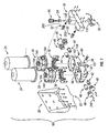
- a dual cartridge desiccator system wherein air is subjected to oil separation by a novel device used in conjunction with a well or like housing for reversing the direction of air flow, adsorbing the oil in the air stream, passing the air through a filter and through the exterior of a desiccant cartridge, and thereafter passing it down and through the desiccant cartridge, and having it exit by way of a valve to an outlet port.
- the other cartridge is simultaneously regenerated by a controlled amount of bleed air entering the cartridge and flowing backwards through the desiccant contained in that cartridge and ultimately out a drain port controlled by a valve opened by air pressure. This operates the cycle in an opposite direction, all without causing an interruption or a loss of air pressure to the main supply.
- the invention also achieves its objects by providing an electrically operated timer in the same device including a novel oil separator, whereby air pressure is directed to a control for an exhaust or purge valve for wet air and also to the inlet valve for air to be dried, while also providing certain auxiliary functions.
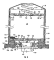
- Fig. 3 is a larger scale view showing that the moisture-laden air flowing in a reverse direction collects in the dished region 222, from which it may pass through port 96, and through the valve 46 to the discharge port 100.
Claims (20)
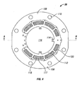
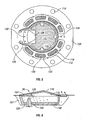
- Système de séchage d'air comprenant deux unités de séchage d'air sensiblement identiques chacune comprenant, dans un mode, une première entrée d'air humide (62), un premier clapet de non-retour d'entrée (42), un premier déshydratant pour sécher l'air (216), une première sortie d'air sec (212), et un premier moyen d'alimentation en air sec a une installation de stockage ledit système comprenant aussi, dans le même mode un premier clapet de vidange (52) alimentant une petite partie dudit air sec a des fins de régénération d'un second deshydratant, et un premier clapet de purge d'air humide (46) a des fins de déversement de l'humidité collectée au cours de la régénération dans lequel ledit premier clapet de non-retour d'entrée (42) et ledit premier clapet de purge d air humide (46) sont positionnés dans un corps de clapet inférieur (32) et sont fonctionnellement raccordés par le biais d un premier passage (86) dans le corps de clapet inférieur (32) à des fins de transmission d'air sous pression entre un espace intérieur (80) dans le premier clapet de non retour d entrée (42) et un espace intérieur (88) dans le premier clapet de purge d'air humide (46) pour fermer le premier clapet de non-retour d'entrée (42) et ouvrir le premier clapet de purge d'air humide (46) ledit système fonctionnant aussi dans un mode oppose et ayant une seconde entrée d air humide (64) un second clapet de non-retour d entrée (40), le second déshydratant, une seconde sortie d'air sec (194) et un second moyen d alimentation en air à une installation de stockage, et un second clapet de vidage (50) alimentant une petite partie dudit air sec à des fins de régénération dudit premier déshydratant et un second clapet de purge d'air humide (44), dans lequel ledit second clapet de non retour d'entrée (40) et ledit second clapet de purge d'air humide (44) sont positionnés dans le corps de clapet inférieur (32) et sont fonctionnellement raccordés par le biais d'un second passage (105) dans le corps de clapet inférieur (32) a des fins de transmission d'air sous pression entre un espace intérieur (104) du second clapet de non-retour d'entrée (40) et un espace intérieur (106) du second clapet de purge d'air humide (44) pour fermer le second clapet de non-retour d'entrée (40) et ouvrir le second clapet de purge d'air humide (44), et se trouvant entre lesdites entrées d'air humide et lesdits deshydratants, une paire de séparateurs air-huile (34, 36) comprenant un moyen définissant une alimentation en air dirigée vers le haut chaque ensemble séparateur air-huile reposant dans un logement (107, 222), lesdits ensembles ayant chacun un plateau déflecteur (128) disposé de manière opposée par rapport à ladite alimentation en air, une section centrale imperforée (116), le plateau défleteur étant situé sous une partie de ladite section centrale imperforée et une cloison verticale (124) entourant au moins partiellement ladite section centrale le moyen de passage d'air reposant à l'extérieur de ladite section centrale imperforée et contenant un milieu filtrant ledit milieu filtrant étant aussi attaché de manière adhesive sur au moins l'une parmi ladite section centrale et ladite cloison, dans lequel lesdits séparateurs air-huile sont adaptés de telle sorte que l'ensemble an et huile entraînéee est dirigé vers ledit plateau déflecteur et change de direction et tourbillonne dans le logement (107) et passe sous ladite cloison et vers le haut au travers dudit moyen de passage d'air reposant à l'extérieur de ladite section centrale imperforée et contenant le milieu filtrant
- Système de séchage d'air selon la revendication 1, dans lequel ledit deshydratant (178) est contenu dans un sac (176), ledit sac étant situé dans une cartouche à visser.
- Système de séchage d'air selon la revendication 1, dans lequel lesdits séparateur air-huile (34, 36) comprennent chacun une partie bride (108) reposant à l'extérieur dudit moyen de passage d'air, ladile partie bride servant aussi à assujettir de manière amovible ledit séparateur airhuile en place à l'intérieur dudit système de séchage d'air.
- Système de séchage d'air selon la revendication 1, dans lequel ledit moyen de passage d'air comporte une pluralité de poches (117), chacune desdites poches contenant ledit milieu filtrant et chacune desdites poches ayant une paire de tamis (118) dans celles-ci renfermant ledit milieu filtrant entre ceux-ci.
- Système de séchage d'air selon la revendication 1, dans lequel ladite section centrale imperforée est sous la forme d'un poteau avant un dôme conique peu profond.
- Système de séchage d'air selon la revendication 1, dans lequel ledit milieu filtrant comporte une matière fibreuse aramide.
- Système de séchage d'air selon la revendication 6, dans lequel ladite matière fibreuse aramide est formée en un tapis non tissé.
- Système de séchage d'air selon la revendication 7 dans lequel ladite matière fibreuse aramid recouvre à la fois l'intérieur de ladite section centrale et les surfaces intérieures de ladite section centrale, ledit tapis étant assujetti à ladite section centrage et à ladite cloison par une matière adhésive.
- Système de séchage d'air selon la revendication 1, qui comprend un moyen permettant de retirer lesdites première et seconde entrées d'air humide.
- Système de séchage d'air selon la revendication 1, qui comprend un moyen permettant de retirer et de remplacer lesdits premier et second clapets de vidange.
- Système de séchage d'air selon la revendication 1, lesdits séparateurs air-huile (34, 36) étant disposés lors de l'utilisation entre lesdits premier et second clapets de non-retour d'entrée d'air (40, 42) et lesdits premier et second déshydratants, chaque dit séparateur air-huile comprenant une plaque bride (108) à des fins d'obturation dudit logement (107, 222) en amont par rapport audits premier et second clapets d'entrée d'air, ledit moyen de passage d'air comportant au moins une ouverture dans ladite plique bride pour permettre un écoulement d'air au travers de celle-ci, ledit milieu filtrant étant disposé à l'intérieur dudit moyen de passage d'air, un plateau déflecteur étant sous une partie de ladite section centrale, ladite cloison s'étendant vers le bas depuis ladite section centrale, et une marge (126), ledit milieu filtrant recouvrant aussi une surface inférieure de ladite section centrale et la surface intérieure de ladite cloison, ladite marge (126) étant définie par une zone de matière fibreuse aramide s'étendant sous ladite cloison, lesdits premier et second clapets de non-retour d'entrée d'air dirigeant l'air et l'huile entraînée vers ledit plateau déflecteur, et ledit air passant ensuite sous ladite cloison et vers le haut au travers dudit moyen de passage d'air jusqu'audit déshydratant.
- Système de séchage d'air selon à revendication 11, dans lequel ledit milieu filtrant est une matière tensioactive ayant tendance à absorber l'huile sur sa surface en provenance de l'air contentant l'huile et étant chargée sous pression sur ledit déshydratant, et à désorber ladite huile quand l'air s'écoute sur ladite matière en provenance dudit déshydratant.
- Système de séchage d'air selon la revendication 11, dans lequel ledit milieu filtrant est réalisé à partir d'une matière fibreuse aramide.
- Système de séchage d'air selon la revendication 13 dans lequel ladite fibre aramide est sous la forme d'une matière fibreuse non tissée.
- Système de séchage d'air selon la revendication 11, dans lequel ledit milieu filtrant est assujetti de manière adhésive à la fois sur ladite cloison et ladite section centrale.
- Système de séchage d'air selon la revendication 11, dans lequel ledit moyen de passage d'air comporte plusieurs ouvertures
- Système de séchage d'air selon la revendication 11, dans lequel ledit moyen de passage d'air comprend des tamis supérieur et inférieur piégeant ledit matériau filtrant entre ceux-ci
- Système de séchage d'air selon la revendication 11, dans lequel ledit moyen de passage d'air comporte une pluralité d'ouvertures, lesdites ouvertures comportant une poche inférieure, un tamis inférieur, une charge de matériau filtrant, un tamis supérieur et un couvercle de poche supérieure.
- Système de séchage d'air selon la revendication 11, dans lequel ladite section centrale imperforée comprend une section en forme de dôme.
- Système de séchage d'air selon la revendication 1, comprenant par ailleurs un corps de clapet (32) définissant un premier passage (86) qui raccorde de manière fluidique un espace intérieur (80) dudit premier clapet de non retour d'entrée (42) sur ledit premier clapet de purge d'air humide (46) et ledit corps de clapet (32) définissant par ailleurs un second passage (105) qui raccorde de manière fluidique un espace intérieur (104) dudit second clapet de non-retour d'entrée (40) sur ledit second clapet de purge d'air humide (44) dans lequel dans ledit même mode de l'air sous pression est passé au travers d un premier orifice (84) jusque dans l'espace intérieur (80) dudit premier clapet de non-retour d'entrée (42) et au travers d un premier passage (86) jusque dans le premier clapet de purge d'air humide (46) et dans ledit mode oppose de l'air sous pression est passé au travers d un second orifice (102) jusque dans l'espace intérieur (104) du second clapet de non-retour d'entrée (40) et au travers du second passage (105) jusque dans ledit second clapet de purge d'air humide (44).
Applications Claiming Priority (2)
| Application Number | Priority Date | Filing Date | Title |
|---|---|---|---|
| US10/788,872 US7097696B2 (en) | 2004-02-27 | 2004-02-27 | Dual cartridge air dryer with oil separator and readily changeable valves |
| PCT/US2005/003661 WO2005091783A2 (fr) | 2004-02-27 | 2005-02-08 | Sechoir a air a double cartouche presentant un separateur d'huile et des vannes facilement remplacables |
Publications (3)
| Publication Number | Publication Date |
|---|---|
| EP1718392A2 EP1718392A2 (fr) | 2006-11-08 |
| EP1718392A4 EP1718392A4 (fr) | 2009-08-19 |
| EP1718392B1 true EP1718392B1 (fr) | 2014-07-16 |
Family
ID=34887111
Family Applications (1)
| Application Number | Title | Priority Date | Filing Date |
|---|---|---|---|
| EP05712921.5A Not-in-force EP1718392B1 (fr) | 2004-02-27 | 2005-02-08 | Sechoir a air a double cartouche presentant un separateur d'huile et des vannes facilement remplacables |
Country Status (10)
| Country | Link |
|---|---|
| US (1) | US7097696B2 (fr) |
| EP (1) | EP1718392B1 (fr) |
| JP (2) | JP5325419B2 (fr) |
| KR (1) | KR101128881B1 (fr) |
| CN (1) | CN1921924B (fr) |
| AU (1) | AU2005227045B2 (fr) |
| BR (1) | BRPI0507996A (fr) |
| CA (1) | CA2557332C (fr) |
| NZ (1) | NZ548964A (fr) |
| WO (1) | WO2005091783A2 (fr) |
Cited By (1)
| Publication number | Priority date | Publication date | Assignee | Title |
|---|---|---|---|---|
| DE102016006095A1 (de) | 2015-07-16 | 2017-01-19 | Mann+Hummel Gmbh | Abscheidemodul, Leitungsmodul sowie Entlüftungsvorrichtung |
Families Citing this family (40)
| Publication number | Priority date | Publication date | Assignee | Title |
|---|---|---|---|---|
| DE102004059508C5 (de) * | 2004-12-10 | 2008-07-03 | Haldex Brake Products Gmbh | Verfahren zum Reinigen von Druckluft an Druckluftbeschaffungsanlagen von Kraftfahrzeugen sowie Kartusche hierfür |
| TWI291367B (en) * | 2006-06-09 | 2007-12-21 | Bossmen Inc | Air drying device for air dryer |
| US7992667B2 (en) * | 2006-08-08 | 2011-08-09 | David Wayne Rennie | Oil cooling and filtering system, kit and apparatus |
| US20080098564A1 (en) * | 2006-10-24 | 2008-05-01 | Fojtik Shawn P | Locking Hinges for Syringe Handles, Syringes Including Locking Hinges, and Associated Methods |
| US7981194B2 (en) * | 2006-11-10 | 2011-07-19 | Bendix Commercial Vehicle Systems Llc | Air drying arrangement |
| ITUD20070024A1 (it) * | 2007-02-07 | 2008-08-08 | Ohg Ind O M I Srl | Gruppo di filtraggio per uno scambiatore di calore |
| US7635409B2 (en) | 2007-03-09 | 2009-12-22 | Skf Usa Inc. | Air dryer systems |
| CN101306291B (zh) * | 2007-05-15 | 2011-10-05 | 淳靖股份有限公司 | 旋风式油细分离罐 |
| GB0719917D0 (en) | 2007-10-11 | 2007-11-21 | Walker Filtration Ltd | Regenerative adsorption gas dryer |
| DE102007050853B3 (de) * | 2007-10-24 | 2009-05-07 | Dräger Medical AG & Co. KG | Einmalabsorber mit Adapter und Lippendichtung |
| US8663375B2 (en) | 2009-01-14 | 2014-03-04 | Nabtesco Automotive Corporation | Oil suppressing structure in air drying device |
| JP5542388B2 (ja) * | 2009-08-11 | 2014-07-09 | ナブテスコオートモーティブ株式会社 | 空気乾燥装置 |
| US8776834B2 (en) * | 2009-09-02 | 2014-07-15 | Rick Kirby | Device for the deflection of the air jet pulse from the air dryer of large truck air brakes |
| DE102010024889B4 (de) * | 2010-06-24 | 2014-12-11 | Wabco Gmbh | Luftversorgungseinrichtung für ein Fahrzeug mit pneumatischen Einrichtungen |
| US9017460B2 (en) * | 2010-11-15 | 2015-04-28 | Nabtesco Automotive Corporation | Silencer, exhaust valve, valve device, air dryer, compressed air supply device for vehicle, and compressed air supply system |
| EP2641648B1 (fr) | 2010-11-15 | 2019-08-21 | Nabtesco Automotive Corporation | Silencieux, soupape d'évacuation, dispositif soupape, sécheur d'air, dispositif d'alimentation en air comprimé pour un véhicule et système d'alimentation en air comprimé |
| US8557030B2 (en) | 2011-04-06 | 2013-10-15 | Bendix Commercial Vehicle Systems Llc | Air dryer assembly |
| US8999045B2 (en) * | 2012-01-05 | 2015-04-07 | Suburban Manufacturing, Inc. | Regenerative air dryer |
| EP2821604B1 (fr) | 2012-02-27 | 2022-01-12 | Nabtesco Automotive Corporation | Séparateur d'huile |
| CN104350247B (zh) | 2012-02-27 | 2017-12-15 | 纳薄特斯克汽车零部件有限公司 | 油分离器 |
| CN106150978B (zh) | 2012-02-27 | 2020-02-28 | 纳博特斯克汽车零部件有限公司 | 分油器 |
| IN2014MN02360A (fr) | 2012-05-10 | 2015-08-14 | Nabtesco Automotive Corp | |
| EP2889484B1 (fr) | 2012-07-02 | 2020-06-03 | Nabtesco Automotive Corporation | Séparateur d'huile |
| DE102012108581B3 (de) * | 2012-09-13 | 2014-01-23 | Knorr-Bremse Systeme für Schienenfahrzeuge GmbH | Kompakte Lufttrocknungsanlage mit modularem Aufbau |
| US9457785B2 (en) | 2012-10-30 | 2016-10-04 | Bendix Commercial Vehicle Systems, Llc | Heat-exchange dryer apparatus, system and method |
| GB201303496D0 (en) | 2013-02-27 | 2013-04-10 | Norgren Ltd C A | Filter with optimized fluid flows |
| US9375679B2 (en) | 2013-08-30 | 2016-06-28 | Haldex Brake Products Corporation | Air dryer assembly with manifold system |
| DE112014005632T5 (de) * | 2013-12-12 | 2016-10-06 | Nabtesco Automotive Corporation | Drucklufttrocknungsvorrichtung |
| CN104083995B (zh) * | 2014-07-25 | 2017-05-17 | 株洲壹星科技股份有限公司 | 空气压缩机无热吸附空气干燥方法及模块式空气干燥机 |
| DE102015122168A1 (de) * | 2015-12-18 | 2017-06-22 | Knorr-Bremse Systeme für Nutzfahrzeuge GmbH | Lufttrocknerpatrone |
| JP6728966B2 (ja) * | 2016-05-19 | 2020-07-22 | アイシン精機株式会社 | エアサスペンション用ドライヤ |
| JP6441392B2 (ja) * | 2017-02-15 | 2018-12-19 | ナブテスコオートモーティブ株式会社 | オイルセパレータ、圧縮空気供給装置、及び車両 |
| DE102018000981A1 (de) * | 2017-03-08 | 2018-09-13 | Mann+Hummel Gmbh | Strömungsoptimierte Trockenmittelkartusche |
| US10807582B2 (en) * | 2018-03-27 | 2020-10-20 | Bendix Commercial Vehicle Systems Llc | Effluent processing apparatus and method for a vehicle air brake charging system |
| CN108434944A (zh) * | 2018-04-18 | 2018-08-24 | 广州市汉粤净化科技有限公司 | 一种带三个吸附筒的干燥机 |
| CN110979285B (zh) * | 2019-12-16 | 2021-02-23 | 扬州市奥特瑞汽车电子科技有限公司 | 一种汽车气管路复合净化装置 |
| BE1028303B1 (nl) * | 2020-05-13 | 2021-12-16 | Atlas Copco Airpower Nv | Inrichting en werkwijze voor het adsorberen van een gas uit een te behandelen gasmengsel |
| CN111994062B (zh) * | 2020-08-28 | 2021-11-12 | 东风商用车有限公司 | 一种气制动空气干燥器、气制动控制系统和车辆 |
| EP4265319A1 (fr) * | 2020-12-18 | 2023-10-25 | Semyungtech Co., Ltd. | Cartouche de sécheur d'air |
| EP4026603A1 (fr) * | 2021-01-12 | 2022-07-13 | KNORR-BREMSE Systeme für Nutzfahrzeuge GmbH | Récipient de déshydratant, cartouche de séchage à l'air et dispositif de traitement d'air |
Family Cites Families (27)
| Publication number | Priority date | Publication date | Assignee | Title |
|---|---|---|---|---|
| US3891417A (en) * | 1974-01-28 | 1975-06-24 | King Eng Corp | Filter and sorbent cartridge |
| US4108617A (en) * | 1977-02-07 | 1978-08-22 | Graham-White Sales Corp. | Dual filter assembly |
| US4468239A (en) * | 1983-01-07 | 1984-08-28 | Roanoke College | Twin tower assembly for decontaminating compressed gas |
| US4692175A (en) * | 1986-03-17 | 1987-09-08 | Roanoke College | Two-stage precoalescer unit |
| US5209764A (en) * | 1991-08-20 | 1993-05-11 | Allied Signal Inc. | Compressed air system with twin air dryers |
| US5378266A (en) * | 1993-08-02 | 1995-01-03 | Alliedsignal Inc. | Air dryer system |
| JP2789426B2 (ja) * | 1994-06-03 | 1998-08-20 | ウエツトマスター株式会社 | 蒸気の減圧兼ドレン分離方法及びその装置 |
| DE4429822C2 (de) * | 1994-08-23 | 1998-02-19 | Mann & Hummel Filter | Vorrichtung zum Abscheiden von Ölaerosol aus Luft |
| DE9419512U1 (de) * | 1994-12-06 | 1995-02-02 | Mann & Hummel Filter | Flansch, insbesondere für eine Vorrichtung zum Abscheiden von Ölaerosol aus Luft |
| JPH08173740A (ja) * | 1994-12-27 | 1996-07-09 | Tokai Rubber Ind Ltd | ミスト除去装置 |
| JPH09117625A (ja) * | 1995-10-24 | 1997-05-06 | Tokai Rubber Ind Ltd | オイル回収装置 |
| AUPN877296A0 (en) * | 1996-03-19 | 1996-04-18 | General Pneumatics Pty Ltd | Compressed air filter |
| JPH1176723A (ja) * | 1997-09-05 | 1999-03-23 | Mitsubishi Electric Corp | オイルミストトラップ |
| US5901459A (en) * | 1997-11-26 | 1999-05-11 | Westinghouse Air Brake Company | Shuttle mechanism for twin tower air dryer system |
| US5901464A (en) * | 1997-11-26 | 1999-05-11 | Westinghouse Air Brake Company | E-1 twin tower air dryer for an air compressor unit |
| US6000432A (en) * | 1997-11-26 | 1999-12-14 | Westinghouse Air Brake Company | Control valve with axial sealing |
| JP3107375B2 (ja) * | 1997-12-18 | 2000-11-06 | 清武 遠藤 | オイルミスト捕集装置 |
| US6014820A (en) * | 1998-02-02 | 2000-01-18 | Westinghouse Air Brake Company | Shuttle valve for twin tower air dryer |
| US5961698A (en) * | 1998-02-02 | 1999-10-05 | Westinghouse Air Brake Company | Twin tower air dryer |
| SE9800843L (sv) * | 1998-03-16 | 1999-09-17 | Haldex Brake Prod Ab | Lufttorkare |
| US6094836A (en) * | 1999-04-12 | 2000-08-01 | Skf Usa Inc. | Dual air dryer with spin-on cartridges |
| DE10051307B4 (de) * | 2000-10-17 | 2008-07-31 | Robert Bosch Gmbh | Vorrichtung zur Trennung von Gas und Flüssigkeit-Festkörperpartikeln aus einem in einer Leitung strömenden Gas-Flüssigkeit-Festkörperpartikelgemisch und Verfahren zur Trennung derselben |
| US6581297B1 (en) * | 2000-11-17 | 2003-06-24 | Graham-White Manufacturing Company | Drying apparatus and method |
| US6641633B2 (en) * | 2001-04-23 | 2003-11-04 | Julian L. Witengier | Gas/liquid separator for a pneumatic line |
| JP2002357376A (ja) * | 2001-06-01 | 2002-12-13 | Mitsubishi Electric Corp | 油分離器 |
| JP4723130B2 (ja) * | 2001-08-08 | 2011-07-13 | シーケーディ株式会社 | 吸着分離装置 |
| US20040118092A1 (en) * | 2002-12-20 | 2004-06-24 | Honeywell International Inc. | High strength and ultra-efficient oil coalescer |
-
2004
- 2004-02-27 US US10/788,872 patent/US7097696B2/en active Active
-
2005
- 2005-02-08 WO PCT/US2005/003661 patent/WO2005091783A2/fr active Search and Examination
- 2005-02-08 BR BRPI0507996-9A patent/BRPI0507996A/pt not_active IP Right Cessation
- 2005-02-08 CA CA2557332A patent/CA2557332C/fr not_active Expired - Fee Related
- 2005-02-08 EP EP05712921.5A patent/EP1718392B1/fr not_active Not-in-force
- 2005-02-08 JP JP2007500850A patent/JP5325419B2/ja not_active Expired - Fee Related
- 2005-02-08 KR KR1020067016811A patent/KR101128881B1/ko not_active IP Right Cessation
- 2005-02-08 NZ NZ548964A patent/NZ548964A/xx not_active IP Right Cessation
- 2005-02-08 AU AU2005227045A patent/AU2005227045B2/en not_active Ceased
- 2005-02-08 CN CN200580006029XA patent/CN1921924B/zh not_active Expired - Fee Related
-
2012
- 2012-02-01 JP JP2012019977A patent/JP2012130917A/ja active Pending
Cited By (2)
| Publication number | Priority date | Publication date | Assignee | Title |
|---|---|---|---|---|
| DE102016006095A1 (de) | 2015-07-16 | 2017-01-19 | Mann+Hummel Gmbh | Abscheidemodul, Leitungsmodul sowie Entlüftungsvorrichtung |
| DE102016006095B4 (de) | 2015-07-16 | 2023-05-25 | Mann+Hummel Gmbh | Abscheidemodul, Leitungsmodul sowie Entlüftungsvorrichtung |
Also Published As
| Publication number | Publication date |
|---|---|
| US7097696B2 (en) | 2006-08-29 |
| JP2007525324A (ja) | 2007-09-06 |
| NZ548964A (en) | 2009-07-31 |
| US20050188848A1 (en) | 2005-09-01 |
| CA2557332C (fr) | 2013-05-07 |
| KR20070001963A (ko) | 2007-01-04 |
| WO2005091783A3 (fr) | 2006-03-16 |
| AU2005227045A1 (en) | 2005-10-06 |
| BRPI0507996A (pt) | 2007-07-31 |
| WO2005091783A2 (fr) | 2005-10-06 |
| KR101128881B1 (ko) | 2012-03-26 |
| EP1718392A2 (fr) | 2006-11-08 |
| JP5325419B2 (ja) | 2013-10-23 |
| EP1718392A4 (fr) | 2009-08-19 |
| CN1921924B (zh) | 2011-08-03 |
| CN1921924A (zh) | 2007-02-28 |
| CA2557332A1 (fr) | 2005-10-06 |
| AU2005227045B2 (en) | 2009-11-12 |
| JP2012130917A (ja) | 2012-07-12 |
Similar Documents
| Publication | Publication Date | Title |
|---|---|---|
| EP1718392B1 (fr) | Sechoir a air a double cartouche presentant un separateur d'huile et des vannes facilement remplacables | |
| JP2007525324A5 (fr) | ||
| KR101273987B1 (ko) | 공기 건조기 카트리지 | |
| US3464186A (en) | Dryer for compressed fluid systems | |
| US8557030B2 (en) | Air dryer assembly | |
| RU2492915C2 (ru) | Патрон для осушителя воздуха (варианты) | |
| US7625436B2 (en) | Air dryer cartridge | |
| US6094836A (en) | Dual air dryer with spin-on cartridges | |
| EP0073895A1 (fr) | Appareil pour décontaminer des gaz comprimés | |
| CA2233311C (fr) | Soupape de commande avec scellage axial | |
| US4199331A (en) | Dual filter assembly for compressed gas | |
| MXPA06009139A (en) | Dual cartridge air dryer with oil separator and readily changeable valves | |
| KR102490306B1 (ko) | 상용차용 공기 건조기 카트리지 | |
| JPH061223Y2 (ja) | エアドライヤ装置 | |
| JPH06247284A (ja) | 車両用圧縮空気の浄化装置 | |
| JP2570431Y2 (ja) | 除湿器 | |
| JPH0664713U (ja) | 除湿器 | |
| JP2002028434A (ja) | 気体の除湿装置 |
Legal Events
| Date | Code | Title | Description |
|---|---|---|---|
| PUAI | Public reference made under article 153(3) epc to a published international application that has entered the european phase |
Free format text: ORIGINAL CODE: 0009012 |
|
| 17P | Request for examination filed |
Effective date: 20060807 |
|
| AK | Designated contracting states |
Kind code of ref document: A2 Designated state(s): AT BE BG CH CY CZ DE DK EE ES FI FR GB GR HU IE IS IT LI LT LU MC NL PL PT RO SE SI SK TR |
|
| DAX | Request for extension of the european patent (deleted) | ||
| A4 | Supplementary search report drawn up and despatched |
Effective date: 20090717 |
|
| RIC1 | Information provided on ipc code assigned before grant |
Ipc: B01D 53/04 20060101AFI20060901BHEP Ipc: B01D 46/00 20060101ALI20090713BHEP Ipc: B60T 17/00 20060101ALI20090713BHEP Ipc: B01D 45/08 20060101ALI20090713BHEP |
|
| 17Q | First examination report despatched |
Effective date: 20101202 |
|
| GRAP | Despatch of communication of intention to grant a patent |
Free format text: ORIGINAL CODE: EPIDOSNIGR1 |
|
| INTG | Intention to grant announced |
Effective date: 20131217 |
|
| GRAS | Grant fee paid |
Free format text: ORIGINAL CODE: EPIDOSNIGR3 |
|
| GRAA | (expected) grant |
Free format text: ORIGINAL CODE: 0009210 |
|
| AK | Designated contracting states |
Kind code of ref document: B1 Designated state(s): AT BE BG CH CY CZ DE DK EE ES FI FR GB GR HU IE IS IT LI LT LU MC NL PL PT RO SE SI SK TR |
|
| REG | Reference to a national code |
Ref country code: GB Ref legal event code: FG4D |
|
| REG | Reference to a national code |
Ref country code: CH Ref legal event code: EP |
|
| REG | Reference to a national code |
Ref country code: IE Ref legal event code: FG4D |
|
| REG | Reference to a national code |
Ref country code: AT Ref legal event code: REF Ref document number: 677228 Country of ref document: AT Kind code of ref document: T Effective date: 20140815 |
|
| REG | Reference to a national code |
Ref country code: DE Ref legal event code: R096 Ref document number: 602005044191 Country of ref document: DE Effective date: 20140828 |
|
| REG | Reference to a national code |
Ref country code: NL Ref legal event code: VDEP Effective date: 20140716 |
|
| REG | Reference to a national code |
Ref country code: AT Ref legal event code: MK05 Ref document number: 677228 Country of ref document: AT Kind code of ref document: T Effective date: 20140716 |
|
| REG | Reference to a national code |
Ref country code: LT Ref legal event code: MG4D |
|
| PG25 | Lapsed in a contracting state [announced via postgrant information from national office to epo] |
Ref country code: FI Free format text: LAPSE BECAUSE OF FAILURE TO SUBMIT A TRANSLATION OF THE DESCRIPTION OR TO PAY THE FEE WITHIN THE PRESCRIBED TIME-LIMIT Effective date: 20140716 Ref country code: LT Free format text: LAPSE BECAUSE OF FAILURE TO SUBMIT A TRANSLATION OF THE DESCRIPTION OR TO PAY THE FEE WITHIN THE PRESCRIBED TIME-LIMIT Effective date: 20140716 Ref country code: GR Free format text: LAPSE BECAUSE OF FAILURE TO SUBMIT A TRANSLATION OF THE DESCRIPTION OR TO PAY THE FEE WITHIN THE PRESCRIBED TIME-LIMIT Effective date: 20141017 Ref country code: PT Free format text: LAPSE BECAUSE OF FAILURE TO SUBMIT A TRANSLATION OF THE DESCRIPTION OR TO PAY THE FEE WITHIN THE PRESCRIBED TIME-LIMIT Effective date: 20141117 Ref country code: SE Free format text: LAPSE BECAUSE OF FAILURE TO SUBMIT A TRANSLATION OF THE DESCRIPTION OR TO PAY THE FEE WITHIN THE PRESCRIBED TIME-LIMIT Effective date: 20140716 Ref country code: BG Free format text: LAPSE BECAUSE OF FAILURE TO SUBMIT A TRANSLATION OF THE DESCRIPTION OR TO PAY THE FEE WITHIN THE PRESCRIBED TIME-LIMIT Effective date: 20141016 Ref country code: ES Free format text: LAPSE BECAUSE OF FAILURE TO SUBMIT A TRANSLATION OF THE DESCRIPTION OR TO PAY THE FEE WITHIN THE PRESCRIBED TIME-LIMIT Effective date: 20140716 |
|
| PG25 | Lapsed in a contracting state [announced via postgrant information from national office to epo] |
Ref country code: IS Free format text: LAPSE BECAUSE OF FAILURE TO SUBMIT A TRANSLATION OF THE DESCRIPTION OR TO PAY THE FEE WITHIN THE PRESCRIBED TIME-LIMIT Effective date: 20141116 Ref country code: AT Free format text: LAPSE BECAUSE OF FAILURE TO SUBMIT A TRANSLATION OF THE DESCRIPTION OR TO PAY THE FEE WITHIN THE PRESCRIBED TIME-LIMIT Effective date: 20140716 Ref country code: CY Free format text: LAPSE BECAUSE OF FAILURE TO SUBMIT A TRANSLATION OF THE DESCRIPTION OR TO PAY THE FEE WITHIN THE PRESCRIBED TIME-LIMIT Effective date: 20140716 Ref country code: PL Free format text: LAPSE BECAUSE OF FAILURE TO SUBMIT A TRANSLATION OF THE DESCRIPTION OR TO PAY THE FEE WITHIN THE PRESCRIBED TIME-LIMIT Effective date: 20140716 Ref country code: NL Free format text: LAPSE BECAUSE OF FAILURE TO SUBMIT A TRANSLATION OF THE DESCRIPTION OR TO PAY THE FEE WITHIN THE PRESCRIBED TIME-LIMIT Effective date: 20140716 |
|
| REG | Reference to a national code |
Ref country code: DE Ref legal event code: R097 Ref document number: 602005044191 Country of ref document: DE |
|
| PG25 | Lapsed in a contracting state [announced via postgrant information from national office to epo] |
Ref country code: CZ Free format text: LAPSE BECAUSE OF FAILURE TO SUBMIT A TRANSLATION OF THE DESCRIPTION OR TO PAY THE FEE WITHIN THE PRESCRIBED TIME-LIMIT Effective date: 20140716 Ref country code: SK Free format text: LAPSE BECAUSE OF FAILURE TO SUBMIT A TRANSLATION OF THE DESCRIPTION OR TO PAY THE FEE WITHIN THE PRESCRIBED TIME-LIMIT Effective date: 20140716 Ref country code: EE Free format text: LAPSE BECAUSE OF FAILURE TO SUBMIT A TRANSLATION OF THE DESCRIPTION OR TO PAY THE FEE WITHIN THE PRESCRIBED TIME-LIMIT Effective date: 20140716 Ref country code: RO Free format text: LAPSE BECAUSE OF FAILURE TO SUBMIT A TRANSLATION OF THE DESCRIPTION OR TO PAY THE FEE WITHIN THE PRESCRIBED TIME-LIMIT Effective date: 20140716 Ref country code: IT Free format text: LAPSE BECAUSE OF FAILURE TO SUBMIT A TRANSLATION OF THE DESCRIPTION OR TO PAY THE FEE WITHIN THE PRESCRIBED TIME-LIMIT Effective date: 20140716 Ref country code: DK Free format text: LAPSE BECAUSE OF FAILURE TO SUBMIT A TRANSLATION OF THE DESCRIPTION OR TO PAY THE FEE WITHIN THE PRESCRIBED TIME-LIMIT Effective date: 20140716 |
|
| PLBE | No opposition filed within time limit |
Free format text: ORIGINAL CODE: 0009261 |
|
| STAA | Information on the status of an ep patent application or granted ep patent |
Free format text: STATUS: NO OPPOSITION FILED WITHIN TIME LIMIT |
|
| 26N | No opposition filed |
Effective date: 20150417 |
|
| PG25 | Lapsed in a contracting state [announced via postgrant information from national office to epo] |
Ref country code: BE Free format text: LAPSE BECAUSE OF NON-PAYMENT OF DUE FEES Effective date: 20150228 |
|
| REG | Reference to a national code |
Ref country code: DE Ref legal event code: R119 Ref document number: 602005044191 Country of ref document: DE |
|
| PG25 | Lapsed in a contracting state [announced via postgrant information from national office to epo] |
Ref country code: LU Free format text: LAPSE BECAUSE OF FAILURE TO SUBMIT A TRANSLATION OF THE DESCRIPTION OR TO PAY THE FEE WITHIN THE PRESCRIBED TIME-LIMIT Effective date: 20150208 |
|
| REG | Reference to a national code |
Ref country code: CH Ref legal event code: PL |
|
| GBPC | Gb: european patent ceased through non-payment of renewal fee |
Effective date: 20150208 |
|
| PG25 | Lapsed in a contracting state [announced via postgrant information from national office to epo] |
Ref country code: LI Free format text: LAPSE BECAUSE OF NON-PAYMENT OF DUE FEES Effective date: 20150228 Ref country code: MC Free format text: LAPSE BECAUSE OF FAILURE TO SUBMIT A TRANSLATION OF THE DESCRIPTION OR TO PAY THE FEE WITHIN THE PRESCRIBED TIME-LIMIT Effective date: 20140716 Ref country code: CH Free format text: LAPSE BECAUSE OF NON-PAYMENT OF DUE FEES Effective date: 20150228 |
|
| REG | Reference to a national code |
Ref country code: IE Ref legal event code: MM4A |
|
| REG | Reference to a national code |
Ref country code: FR Ref legal event code: ST Effective date: 20151030 |
|
| PG25 | Lapsed in a contracting state [announced via postgrant information from national office to epo] |
Ref country code: SI Free format text: LAPSE BECAUSE OF FAILURE TO SUBMIT A TRANSLATION OF THE DESCRIPTION OR TO PAY THE FEE WITHIN THE PRESCRIBED TIME-LIMIT Effective date: 20140716 |
|
| PG25 | Lapsed in a contracting state [announced via postgrant information from national office to epo] |
Ref country code: IE Free format text: LAPSE BECAUSE OF NON-PAYMENT OF DUE FEES Effective date: 20150208 Ref country code: DE Free format text: LAPSE BECAUSE OF NON-PAYMENT OF DUE FEES Effective date: 20150901 Ref country code: GB Free format text: LAPSE BECAUSE OF NON-PAYMENT OF DUE FEES Effective date: 20150208 |
|
| PG25 | Lapsed in a contracting state [announced via postgrant information from national office to epo] |
Ref country code: FR Free format text: LAPSE BECAUSE OF NON-PAYMENT OF DUE FEES Effective date: 20150302 |
|
| PG25 | Lapsed in a contracting state [announced via postgrant information from national office to epo] |
Ref country code: BE Free format text: LAPSE BECAUSE OF FAILURE TO SUBMIT A TRANSLATION OF THE DESCRIPTION OR TO PAY THE FEE WITHIN THE PRESCRIBED TIME-LIMIT Effective date: 20140716 |
|
| PG25 | Lapsed in a contracting state [announced via postgrant information from national office to epo] |
Ref country code: HU Free format text: LAPSE BECAUSE OF FAILURE TO SUBMIT A TRANSLATION OF THE DESCRIPTION OR TO PAY THE FEE WITHIN THE PRESCRIBED TIME-LIMIT; INVALID AB INITIO Effective date: 20050208 |
|
| PG25 | Lapsed in a contracting state [announced via postgrant information from national office to epo] |
Ref country code: TR Free format text: LAPSE BECAUSE OF FAILURE TO SUBMIT A TRANSLATION OF THE DESCRIPTION OR TO PAY THE FEE WITHIN THE PRESCRIBED TIME-LIMIT Effective date: 20140716 |