EP1714807B2 - Tool for automatically assembling or disassembling a tyre to/from a wheel rim - Google Patents
Tool for automatically assembling or disassembling a tyre to/from a wheel rim Download PDFInfo
- Publication number
- EP1714807B2 EP1714807B2 EP06005915.1A EP06005915A EP1714807B2 EP 1714807 B2 EP1714807 B2 EP 1714807B2 EP 06005915 A EP06005915 A EP 06005915A EP 1714807 B2 EP1714807 B2 EP 1714807B2
- Authority
- EP
- European Patent Office
- Prior art keywords
- tool
- wheel rim
- tyre
- machine
- carrying arm
- Prior art date
- Legal status (The legal status is an assumption and is not a legal conclusion. Google has not performed a legal analysis and makes no representation as to the accuracy of the status listed.)
- Active
Links
Images

Classifications
-
- B—PERFORMING OPERATIONS; TRANSPORTING
- B60—VEHICLES IN GENERAL
- B60C—VEHICLE TYRES; TYRE INFLATION; TYRE CHANGING; CONNECTING VALVES TO INFLATABLE ELASTIC BODIES IN GENERAL; DEVICES OR ARRANGEMENTS RELATED TO TYRES
- B60C25/00—Apparatus or tools adapted for mounting, removing or inspecting tyres
- B60C25/01—Apparatus or tools adapted for mounting, removing or inspecting tyres for removing tyres from or mounting tyres on wheels
- B60C25/05—Machines
- B60C25/132—Machines for removing and mounting tyres
- B60C25/135—Machines for removing and mounting tyres having a tyre support or a tool, movable along wheel axis
- B60C25/138—Machines for removing and mounting tyres having a tyre support or a tool, movable along wheel axis with rotary motion of tool or tyre support
-
- B—PERFORMING OPERATIONS; TRANSPORTING
- B60—VEHICLES IN GENERAL
- B60C—VEHICLE TYRES; TYRE INFLATION; TYRE CHANGING; CONNECTING VALVES TO INFLATABLE ELASTIC BODIES IN GENERAL; DEVICES OR ARRANGEMENTS RELATED TO TYRES
- B60C25/00—Apparatus or tools adapted for mounting, removing or inspecting tyres
- B60C25/01—Apparatus or tools adapted for mounting, removing or inspecting tyres for removing tyres from or mounting tyres on wheels
- B60C25/05—Machines
- B60C25/0563—Tools interacting with the tyre and moved in relation to the tyre during operation
- B60C25/0578—Tools interacting with the tyre and moved in relation to the tyre during operation hooking only
-
- B—PERFORMING OPERATIONS; TRANSPORTING
- B60—VEHICLES IN GENERAL
- B60C—VEHICLE TYRES; TYRE INFLATION; TYRE CHANGING; CONNECTING VALVES TO INFLATABLE ELASTIC BODIES IN GENERAL; DEVICES OR ARRANGEMENTS RELATED TO TYRES
- B60C25/00—Apparatus or tools adapted for mounting, removing or inspecting tyres
- B60C25/01—Apparatus or tools adapted for mounting, removing or inspecting tyres for removing tyres from or mounting tyres on wheels
- B60C25/05—Machines
- B60C25/0563—Tools interacting with the tyre and moved in relation to the tyre during operation
- B60C25/0584—Predetermined tool path, e.g. coulisse, multi-link
Definitions
- the present invention relates to a machine for automatically assembling-disassembling a tyre to/from a wheel rim.
- patent IT-1 319 475 describes a tyre assembling-disassembling machine provided with rotatable means for supporting a wheel rim, and an automatic device for assembling-disassembling a tyre.
- Such an automatic device has a arm extending cantileverwise, which can move both radially and axially with respect to a wheel rim arranged on the rotatable supporting means, that supports a hook-type assembling tool at its free end, the assembling tool being articulated at its head thereby extending transversally with respect to the arm.
- the assembling tool can be controlled to effect angular movements about its axis of rotation by a linkage system controlled by a double-acting jack.
- the tool is located in a lifted position and is lowered by the supporting arm until its hook end contacts the area between tyre and wheel rim, and the tyre bead is pressed downwards.
- the tool is rotated about its articulation pin through an angle ⁇ in the direction in which its free hook-type end moves closer to the wheel rim.
- Such a rotation assists the tyre bead in being hooked by the hook-type end of the tool.
- the tool-carrying arm is caused to move upwards, and thus the tool moves the tyre bead with it until it is extended beyond the wheel rim edge.
- the wheel rim is then set in rotation so that the tyre bead is progressively carried outside the wheel rim edge, while sliding along the hook portion of the tool.
- the tool can be rotated through an angle ⁇ in the direction in which the hook edge moves away from from the wheel rim thereby assisting in the bead extraction.
- the hook back of the tool is facing the wheel rim, whereas the hook portion proper is facing the tyre.
- the tool is not free, but it is driven and held firmly in position during all the steps needed for disassembling the tyre from its control linkage.
- Patent Application No. US-2004/0 055 712 discloses a particular embodiment of an assembling-disassembling tool fully similar to that described in IT-1 319 475 .
- Patent EP-1 459 913 discloses a tyre assembling-disassembling machine provided with a rotatable wheel-carrying table, which can be moved near to, or away from, a rear support upright, and a tyre assembling-disassembling device.
- the assembling-disassembling device is supported by a sleeve slidable along a guide member parallel to the support upright.
- An ear of a tool-carrying bush is articulated to the sleeve, the tool being formed by a rod iron with a hook-shaped end which is mounted for rotation in the bush and can be controlled by a double-acting jack so that it can effect angular movements about the axis of the bush.
- the tool is first moved against the area between bead and wheel rim edge, with its hook-shaped end being tangentially directed with respect to the wheel rim, is then driven beyond the tyre edge, the tool is caused to rotate through about 90° to allow the hook-shaped end thereof to climb over and engage with the edge of the tyre bead, and finally a tyre edge portion is extracted and the wheel is subsequently caused to rotate.
- this assembling-disassembling tool then requires an operation by means of mechanisms controlled by an operator and this, on one hand, results in considerable costs for the tool adjusting and control system, and on the other mistakes are likely to occur owing to a wrong evaluation of the trim (especially the inclination) of the tool with respect to the wheel rim or the tyre, which might result in the tool stumbling in the tyre edge thereby damaging it.
- EP-1 593 533 A2 Another tyre assembling-disassembling machine according to the preamble of claim 1 is disclosed in EP-1 593 533 A2 which falls under the provisions of Article 54 (3) EPC.
- the main object of the present invention is to provide a tyre assembling-disassembling machine provided with a rotatable support for a tyred wheel or wheel rim, which machine makes it possible to assemble-disassemble a tyre with no manual operations by an operator except the positioning of the wheel onto the rotatable support and the tool adjustment.
- Another object of the present invention is to provide a tyre assembling-disassembling tool very simple to manufacture and use which does not require any dead times as required with manual intervention of the operator, apart from manual intervention during the starting step.
- Another object of the present invention is to provide a tyre assembling-disassembling tool obtainable at competitive production costs.
- said plate-like member is articulated in at least one recess or slot formed in said tool-carrying arm, said recess or slot extends in an inclined direction with respect to both the axis of the tool-carrying arm and a direction perpendicular thereto.
- plate-like member is articulated to an end of a link or shackle member, whose other end is articulated to said tool-carrying arm.
- such a tyre assembling-disassembling machine also comprises at least one pair of bead-releasing rollers, which are arranged, in use, on opposite sides with respect to a wheel rim or tyred wheel placed on said machine, and uprights sliding parallel to the axis of a wheel rim or tyred wheel, but along two directions parallel to and spaced apart from a predetermined distance.
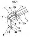
- a tool for assembling-disassembling a tyre P, comprising a tool-carrying arm 2 supported in a radial direction with respect to the tyre at one end thereof by means of a side guide 13a provided in a tyre assembling-disassembling machine with respect to which it can translate in a direction substantially parallel to the axis y-y of the tyre in Fig. 11 , as further explained below.
- the arm 2 at its other end is fork-shaped and has its tines shaped as two side plates 2a and 2b extending parallel to the arm 2.
- the fork 2 is articulated to a plate-like member 3 through a shackle member 4, which, in turn, is articulated to the two side plates 2a and 2b of the fork 2d at one end 5 thereof, and to one end of the plate-like member 3 at its other end 6.
- the plate-like member 3 is substantially plate-like shaped and has its other (free) end substantially hook-shaped and terminating with a cross length 3a arranged to delimit together with the plate-like portion both an inner recess 3b facing, in use, the tool-carrying arm 2, and an outer groove 3c facing away from the recess 3b.
- a respective resilient contrast spring 7 and 7a is provided between plate-like member 3 and shackle member 4, and between the shackle member and tool-carrying arm 2.
- Such springs are suitable for holding the plate-like member 3 in a substantially normal trim with respect to arm 2, whereas the shackle member 4 is held substantially aligned with the arm itself, and act as return members after each trim change, as further described below.
- the tool 1 can be made of any suitable material, preferably an anti-friction plastics material, e.g. nylon (registered TM), which is advantageously reinforced with reinforcing fiber or frameworks, e.g. glass fibers.
- an anti-friction plastics material e.g. nylon (registered TM)
- nylon registered TM
- reinforcing fiber or frameworks e.g. glass fibers.
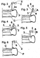
- the tool 1 is caused to abut, at the outer groove 3c of its free end 3a ( Fig. 2 ) against the wheel rim C at a contact area between wheel rim edge and tyre bead by suitably lowering the tool-carrying arm 2; then, while continuing lowering of tool-carrying arm 2 ( Fig.
- the end 3a of the plate-like member is inserted between bead and tyre edge, until the tyre bead is engaged by the plate-like member at the inner recess 3b of the hook-shaped end 3c ( Fig. 4 ).
- the plate-like member 3 in contact with the wheel rim always still at its outer groove rotates about the pin 6 in a such a direction that the end 3a moves near the wheel rim, whereas the shackle member 4 rotates about the pin 5 in the same direction of rotation as that of the plate-like member, thus changing from a substantially horizontal configuration to a substantially vertical configuration.
- Such a double rotation essentially results in a rotational-translational movement of the plate-like member 3 with respect to the tool-carrying arm 2.
- the shackle member 4 is carried to a balance position controlled by the spring 7a with respect to the arm 2, and any further upward movement of the arm 2 will result in the shackle member 4, and consequently the plate-like member 3, being moved upwards, the plate-like member 3 dragging the tyre bead to a position ( Fig. 6 ) in which it is outside the tyre edge, whereas the free end 3a of the plate-like member 3 slidably engages the adjacent edge of the wheel rim at its outer groove 3c.
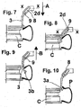
- a device comprising a tool-carrying arm 2 having its fork-shaped end 2d, in which a pair of opposite slots 8 are formed extending according to a inclined direction (e.g. 45°) with respect to the axis x-x of the tool-carrying arm.
- a pin 9 can freely slide in these slots.
- a plate-like member 3 precisely similar that described above has been previously pivoted.
- the arm 2 is caused to move backwards along its guide 13a, whereby a change in the trim of the plate-like member 3 is obtained, the plate-like member taking a trim almost parallel to the axis y-y of the wheel, and, while the backward movement of the arm continues, engaging at the hook-shaped end 3a thereof with the bead inner side until its groove 3c is moved onto the wheel rim edge ( Fig. 10 ), in which position the tyre bead is locally carried outside the wheel rim.
- a self-centering device 11 raises having expansion arms 20 to 23 for rotatably supporting a wheel rim about the axis y-y onto which a tyre is to be assembled, or a tyred wheel from which a respective tyre is to be disassembled.
- the machine 10 is also provided with a pair of bead releasing rollers 17 and 18, one of which 18 is slidably mounted along a guide 13a, the tool-carrying arm 2 being slidable thereon, whereas the other roller 17 is slidably mounted on a guide 13b parallel to the guide 13a, the guides being attached to an upright or rear column 13 of the machine usually provided in an assembling-disassembling machine.
- the tool-carrying arm can be controlled by a double-acting jack 130a, whereas the bead releasing rollers 17 and 18 are controlled to slide along respective sliding guides by means of a respective double-acting jack 130b (only one being shown in Fig. 11 ).
- rollers are mounted offset with respect to the rotatable self-centering device 11, i.e. they are located on opposite sides with respect to a wheel rim-tyre assembly, as they are slidably mounted on guides 13a and 13b parallel but displaced of a prescribed distance from one another, so as to be located and act, in use, on opposite beads of a tyre, but on opposite sides with respect to the plate-like member 3.
- a control lever 14 is also constrained to the column 13 and provided with a knob carrying a control push-bottom panel and two pedals 25 and 26 arranged in the base, as is known in the art.
- the bead releasing rollers are cantileverwise supported by means of supporting telescopic arms 15 and 16, which automatically expand and contract according to the various diameters of the wheels on which to act.
- an assembling-disassembling device does not require a particularly skilled operator.
- the tool-carrying arm 2 can be telescopic with automatic expansion/contraction movements to be adapted to various tyred-wheel diameters.
Landscapes
- Engineering & Computer Science (AREA)
- Mechanical Engineering (AREA)
- Tires In General (AREA)
- Automatic Assembly (AREA)
- Automobile Manufacture Line, Endless Track Vehicle, Trailer (AREA)
- Heating, Cooling, Or Curing Plastics Or The Like In General (AREA)
- Tyre Moulding (AREA)
- Moulds For Moulding Plastics Or The Like (AREA)
Applications Claiming Priority (1)
| Application Number | Priority Date | Filing Date | Title |
|---|---|---|---|
| IT000037A ITVR20050037A1 (it) | 2005-03-23 | 2005-03-23 | Utensile per il montaggio/smontaggio automatico di un pneumatico su/da un cerchione |
Publications (3)
| Publication Number | Publication Date |
|---|---|
| EP1714807A1 EP1714807A1 (en) | 2006-10-25 |
| EP1714807B1 EP1714807B1 (en) | 2009-07-01 |
| EP1714807B2 true EP1714807B2 (en) | 2019-03-27 |
Family
ID=36622238
Family Applications (1)
| Application Number | Title | Priority Date | Filing Date |
|---|---|---|---|
| EP06005915.1A Active EP1714807B2 (en) | 2005-03-23 | 2006-03-23 | Tool for automatically assembling or disassembling a tyre to/from a wheel rim |
Country Status (8)
| Country | Link |
|---|---|
| US (1) | US7497761B2 (enExample) |
| EP (1) | EP1714807B2 (enExample) |
| JP (1) | JP4836247B2 (enExample) |
| CN (1) | CN1935540B (enExample) |
| AT (1) | ATE435130T1 (enExample) |
| DE (1) | DE602006007513D1 (enExample) |
| ES (1) | ES2329067T5 (enExample) |
| IT (1) | ITVR20050037A1 (enExample) |
Families Citing this family (34)
| Publication number | Priority date | Publication date | Assignee | Title |
|---|---|---|---|---|
| DE502007002397D1 (de) | 2007-01-15 | 2010-02-04 | Snap On Equipment S R L A Unic | Vorrichtung zum Montieren oder Demontieren eines Luftreifens von einer Felge eines Fahrzeugrades |
| US7975579B1 (en) * | 2007-04-24 | 2011-07-12 | Eagle International, Llc | System and method for cutting tires |
| ITMO20070350A1 (it) * | 2007-11-21 | 2009-05-22 | Giuliano Spa | Macchina per il montaggio e lo smontaggio di pneumatici di ruote per veicoli |
| JP2009227006A (ja) * | 2008-03-19 | 2009-10-08 | Onodani Kiko Kk | タイヤ着脱装置のタイヤビード案内装置 |
| ITVR20080050A1 (it) * | 2008-04-28 | 2009-10-29 | Butler Eng & Marketing | Gruppo stallonatore per una macchina monta-smontagomme |
| ITRE20080044A1 (it) * | 2008-05-15 | 2009-11-16 | Corghi Spa | "metodo e macchina per lo smontaggio di pneumatici" |
| IT1393290B1 (it) | 2008-09-08 | 2012-04-20 | M&B Engineering S R L | Dispositivo per il montaggio e lo smontaggio di pneumatici |
| JP5026477B2 (ja) * | 2009-07-30 | 2012-09-12 | 小野谷機工株式会社 | タイヤ上ビードの取外し方法及びその装置 |
| CN101934689A (zh) * | 2009-06-30 | 2011-01-05 | 小野谷机工株式会社 | 胎圈拆卸臂及备有胎圈拆卸臂的轮胎拆卸装置及轮胎拆卸方法 |
| JP5026473B2 (ja) * | 2009-06-30 | 2012-09-12 | 小野谷機工株式会社 | タイヤ上ビードの取外し方法 |
| JP5026481B2 (ja) * | 2009-08-22 | 2012-09-12 | 小野谷機工株式会社 | 回転テーブルを備えたタイヤ着脱装置 |
| US8136567B2 (en) * | 2009-11-24 | 2012-03-20 | Aymar Brandon P | Car tire attachment mechanism |
| FR2957417B1 (fr) * | 2010-03-15 | 2013-01-04 | Michelin Soc Tech | Dispositif de maintien destine a l'inspection visuelle d'un pneumatique |
| US8973640B1 (en) | 2010-12-07 | 2015-03-10 | Hunter Engineering Company | Demount tool assembly and methods for automated tire changer machine |
| IT1403058B1 (it) * | 2010-12-09 | 2013-09-27 | Butler Eng & Marketing | Dispositivo di smontaggio di un pneumatico da un cerchione nonché macchina smontagomme dotata di tale dispositivo |
| CA2826851C (en) * | 2011-02-11 | 2019-03-19 | Austin Engineering Ltd | Article handling apparatus |
| CN103874593B (zh) * | 2011-10-06 | 2016-08-17 | 普利司通美国轮胎运营有限责任公司 | 用于安装轮胎的方法和装置 |
| ITMO20120009A1 (it) * | 2012-01-16 | 2013-07-17 | Gino Ferrari | Dispositivo estrattore per macchine smontagomme |
| ITBO20120189A1 (it) * | 2012-04-11 | 2013-10-12 | Corghi Spa | Utensile di smontaggio per una macchina smontagomme e macchina smontagomme |
| ITVR20120159A1 (it) * | 2012-08-01 | 2014-02-02 | Butler Engineering And Marketing S P A | Dispositivo di smontaggio di un pneumatico da un cerchione e metodo di smontaggio di una ruota gommata |
| ITBO20130523A1 (it) * | 2013-09-25 | 2015-03-26 | Corghi Spa | Utensile di smontaggio di uno pneumatico e macchina smontagomme |
| ITVR20130252A1 (it) * | 2013-11-22 | 2015-05-23 | Butler Engineering And Marketing S P A | Dispositivo di smontaggio di una ruota gommata, nonche' macchina comprendente tale dispositivo. |
| EP3501862B1 (en) | 2014-05-30 | 2022-08-03 | Snap-on Equipment Srl a unico socio | Method for mounting and demounting a tyre to and from a wheel rim |
| US11001108B2 (en) * | 2014-05-30 | 2021-05-11 | Snap-On Equipment Srl A Unico Socio | Mounting/demounting tool unit with preloaded tool |
| EP2949488B1 (en) * | 2014-05-30 | 2019-05-15 | Snap-on Equipment Srl a unico socio | Mounting/demounting tool unit with preloaded tool |
| EP2987661B1 (en) * | 2014-07-28 | 2019-10-23 | Butler Engineering & Marketing S.p.A. | Device for assembling-disassembling a tyred wheel, as well as machine comprising such a device |
| DE202014008932U1 (de) | 2014-11-11 | 2016-03-02 | Snap-On Equipment Srl A Unico Socio | Reifenmontage- und -demontagewerkzeug |
| CN104527344B (zh) * | 2014-12-29 | 2017-01-11 | 营口光明科技有限公司 | 一种安装在拆胎机助手上的胎唇分离器 |
| WO2016136972A1 (ja) * | 2015-02-28 | 2016-09-01 | 株式会社シーパーツ | タイヤ掴みヘッドとそれを含むタイヤ脱着ロボットとタイヤ脱着システム |
| IT201600071778A1 (it) | 2016-07-08 | 2018-01-08 | Butler Eng And Marketing S P A | Gruppo di stallonamento di una ruota gommata e/o di spinta di una porzione di un pneumatico di una ruota gommata |
| IT201900019864A1 (it) * | 2019-10-28 | 2021-04-28 | Beissbarth Gmbh | Macchina smontagomme |
| ES2955697T3 (es) | 2019-11-27 | 2023-12-05 | Cemb S P A | Dispositivo para montar y desmontar un neumático en y de una llanta |
| IT202100006998A1 (it) * | 2021-03-23 | 2022-09-23 | Nexion Spa | Utensile di lavoro per un apparato smontagomme |
| CN115416434B (zh) * | 2022-09-19 | 2023-11-14 | 伺轮智能机器人(南京)有限公司 | 一种自适应轮胎拆装机械手 |
Citations (3)
| Publication number | Priority date | Publication date | Assignee | Title |
|---|---|---|---|---|
| US3267983A (en) † | 1963-10-15 | 1966-08-23 | Julio Villars | Apparatus to pull tyres out from the rims of vehicle wheels |
| EP1177920A2 (en) † | 2000-08-03 | 2002-02-06 | CORGHI S.p.A. | Automatic tyre removal and mounting device, and tyre removal machines equipped therewith |
| EP1398184A1 (en) † | 2002-09-13 | 2004-03-17 | CORGHI S.p.A. | Simplified automatic tyre demounting device, and tyre removal machines equipped therewith |
Family Cites Families (6)
| Publication number | Priority date | Publication date | Assignee | Title |
|---|---|---|---|---|
| JP3626088B2 (ja) * | 2000-11-09 | 2005-03-02 | 小野谷機工株式会社 | 自動車タイヤ取外し方法、およびタイヤ取外し装置 |
| ITVR20010124A1 (it) | 2001-11-22 | 2003-05-22 | Butler Enrineering & Marketing | Testa di stallonatura con unghia per il montaggio/smontaggio di un pneumatico per macchina smontagomme. |
| JP2003320828A (ja) * | 2002-04-30 | 2003-11-11 | Takeuchi Giken Seisakusho:Goushi | チューブレスタイヤのタイヤ着脱装置、およびタイヤ着脱方法 |
| ITMO20030084A1 (it) * | 2003-03-21 | 2004-09-22 | Snap On Equipment Srl A Socio Unico | Dispositivo per il monitoraggio e lo smontaggio di pneumatici di ruote posizionate su tavole portaruote di macchine smontagomme. |
| ITMO20030132A1 (it) * | 2003-05-09 | 2004-11-10 | Giuliano Srl | Macchina per il montaggio e lo smontaggio di pneumatici e cerchi di ruote per veicoli. |
| ITRE20040049A1 (it) * | 2004-05-06 | 2004-08-06 | Corghi Spa | Dispositivo automatico per lo smontaggio ed il montaggio dei pneumatici |
-
2005
- 2005-03-23 IT IT000037A patent/ITVR20050037A1/it unknown
-
2006
- 2006-03-22 US US11/386,517 patent/US7497761B2/en active Active
- 2006-03-23 EP EP06005915.1A patent/EP1714807B2/en active Active
- 2006-03-23 JP JP2006081122A patent/JP4836247B2/ja active Active
- 2006-03-23 DE DE602006007513T patent/DE602006007513D1/de active Active
- 2006-03-23 AT AT06005915T patent/ATE435130T1/de not_active IP Right Cessation
- 2006-03-23 ES ES06005915T patent/ES2329067T5/es active Active
- 2006-03-23 CN CN2006100718900A patent/CN1935540B/zh active Active
Patent Citations (3)
| Publication number | Priority date | Publication date | Assignee | Title |
|---|---|---|---|---|
| US3267983A (en) † | 1963-10-15 | 1966-08-23 | Julio Villars | Apparatus to pull tyres out from the rims of vehicle wheels |
| EP1177920A2 (en) † | 2000-08-03 | 2002-02-06 | CORGHI S.p.A. | Automatic tyre removal and mounting device, and tyre removal machines equipped therewith |
| EP1398184A1 (en) † | 2002-09-13 | 2004-03-17 | CORGHI S.p.A. | Simplified automatic tyre demounting device, and tyre removal machines equipped therewith |
Also Published As
| Publication number | Publication date |
|---|---|
| EP1714807B1 (en) | 2009-07-01 |
| ES2329067T5 (es) | 2019-12-04 |
| EP1714807A1 (en) | 2006-10-25 |
| JP2006298360A (ja) | 2006-11-02 |
| US20060254725A1 (en) | 2006-11-16 |
| ITVR20050037A1 (it) | 2006-09-24 |
| US7497761B2 (en) | 2009-03-03 |
| ATE435130T1 (de) | 2009-07-15 |
| DE602006007513D1 (de) | 2009-08-13 |
| CN1935540B (zh) | 2011-06-15 |
| ES2329067T3 (es) | 2009-11-20 |
| CN1935540A (zh) | 2007-03-28 |
| JP4836247B2 (ja) | 2011-12-14 |
Similar Documents
| Publication | Publication Date | Title |
|---|---|---|
| EP1714807B2 (en) | Tool for automatically assembling or disassembling a tyre to/from a wheel rim | |
| JP5651351B2 (ja) | 乗物の車輪のタイア着脱用機械 | |
| US8973640B1 (en) | Demount tool assembly and methods for automated tire changer machine | |
| EP2524821B1 (en) | Device for the automatic demounting of a tire from a rim and machine equipped with such device | |
| EP2629992B1 (en) | A tyre demounting machine | |
| EP1897709B1 (en) | Machine for fitting and removing vehicle tyres | |
| US10065462B2 (en) | Device for assembling-disassembling a tyred wheel, as well as machine comprising such a device | |
| US20120267055A1 (en) | Method and device for mounting a pneumatic tire | |
| EP2282898B1 (en) | A tyre-changing machine and a relative bead-breaking method | |
| EP2692553B1 (en) | A device for disassembling a tyre from a wheel rim and a method of disassembling a tyred wheel. | |
| US7341090B2 (en) | Assembling-disassembling machine provided with a overturnable mounting-dismounting tool | |
| JP2012240676A5 (enExample) | ||
| CN111016557B (zh) | 用于安装和/或拆卸特别是卡车车轮的车辆车轮的机器 | |
| WO2009138322A1 (en) | A tyre-removing method and a tyre-changing machine | |
| US7946016B2 (en) | Method and machine for removing a tyre fitted with a rigid inner run-flat ring | |
| CN105415988A (zh) | 用于移除和安装车辆的车轮轮胎的机器 | |
| EP4169744A1 (en) | Machine for mounting and demounting a tyre relative to a corresponding rim and wheel servicing method | |
| EP1155880A2 (en) | Machine used to mount and dismount tyres of motor vehicle wheels | |
| EP2514610B1 (en) | A lifting apparatus for tyre changing machines | |
| EP1724129B1 (en) | A device for debeading tyres from wheels positioned on a turntable of a tyre-removing machine | |
| US20050092442A1 (en) | Tire changing machine implement for fitting and removing tires of vehicle wheels |
Legal Events
| Date | Code | Title | Description |
|---|---|---|---|
| PUAI | Public reference made under article 153(3) epc to a published international application that has entered the european phase |
Free format text: ORIGINAL CODE: 0009012 |
|
| AK | Designated contracting states |
Kind code of ref document: A1 Designated state(s): AT BE BG CH CY CZ DE DK EE ES FI FR GB GR HU IE IS IT LI LT LU LV MC NL PL PT RO SE SI SK TR |
|
| AX | Request for extension of the european patent |
Extension state: AL BA HR MK YU |
|
| 17P | Request for examination filed |
Effective date: 20070423 |
|
| AKX | Designation fees paid |
Designated state(s): AT BE BG CH CY CZ DE DK EE ES FI FR GB GR HU IE IS IT LI LT LU LV MC NL PL PT RO SE SI SK TR |
|
| 17Q | First examination report despatched |
Effective date: 20080819 |
|
| GRAP | Despatch of communication of intention to grant a patent |
Free format text: ORIGINAL CODE: EPIDOSNIGR1 |
|
| GRAS | Grant fee paid |
Free format text: ORIGINAL CODE: EPIDOSNIGR3 |
|
| GRAA | (expected) grant |
Free format text: ORIGINAL CODE: 0009210 |
|
| AK | Designated contracting states |
Kind code of ref document: B1 Designated state(s): AT BE BG CH CY CZ DE DK EE ES FI FR GB GR HU IE IS IT LI LT LU LV MC NL PL PT RO SE SI SK TR |
|
| REG | Reference to a national code |
Ref country code: GB Ref legal event code: FG4D |
|
| REG | Reference to a national code |
Ref country code: CH Ref legal event code: EP |
|
| REG | Reference to a national code |
Ref country code: IE Ref legal event code: FG4D |
|
| REF | Corresponds to: |
Ref document number: 602006007513 Country of ref document: DE Date of ref document: 20090813 Kind code of ref document: P |
|
| PLBI | Opposition filed |
Free format text: ORIGINAL CODE: 0009260 |
|
| REG | Reference to a national code |
Ref country code: ES Ref legal event code: FG2A Ref document number: 2329067 Country of ref document: ES Kind code of ref document: T3 |
|
| PG25 | Lapsed in a contracting state [announced via postgrant information from national office to epo] |
Ref country code: SI Free format text: LAPSE BECAUSE OF FAILURE TO SUBMIT A TRANSLATION OF THE DESCRIPTION OR TO PAY THE FEE WITHIN THE PRESCRIBED TIME-LIMIT Effective date: 20090701 |
|
| NLV1 | Nl: lapsed or annulled due to failure to fulfill the requirements of art. 29p and 29m of the patents act | ||
| 26 | Opposition filed |
Opponent name: SNAP-ON EQUIPMENT GMBH Effective date: 20091030 |
|
| PG25 | Lapsed in a contracting state [announced via postgrant information from national office to epo] |
Ref country code: EE Free format text: LAPSE BECAUSE OF FAILURE TO SUBMIT A TRANSLATION OF THE DESCRIPTION OR TO PAY THE FEE WITHIN THE PRESCRIBED TIME-LIMIT Effective date: 20090701 Ref country code: SE Free format text: LAPSE BECAUSE OF FAILURE TO SUBMIT A TRANSLATION OF THE DESCRIPTION OR TO PAY THE FEE WITHIN THE PRESCRIBED TIME-LIMIT Effective date: 20090701 Ref country code: FI Free format text: LAPSE BECAUSE OF FAILURE TO SUBMIT A TRANSLATION OF THE DESCRIPTION OR TO PAY THE FEE WITHIN THE PRESCRIBED TIME-LIMIT Effective date: 20090701 Ref country code: IS Free format text: LAPSE BECAUSE OF FAILURE TO SUBMIT A TRANSLATION OF THE DESCRIPTION OR TO PAY THE FEE WITHIN THE PRESCRIBED TIME-LIMIT Effective date: 20091101 Ref country code: AT Free format text: LAPSE BECAUSE OF FAILURE TO SUBMIT A TRANSLATION OF THE DESCRIPTION OR TO PAY THE FEE WITHIN THE PRESCRIBED TIME-LIMIT Effective date: 20090701 Ref country code: LT Free format text: LAPSE BECAUSE OF FAILURE TO SUBMIT A TRANSLATION OF THE DESCRIPTION OR TO PAY THE FEE WITHIN THE PRESCRIBED TIME-LIMIT Effective date: 20090701 |
|
| PG25 | Lapsed in a contracting state [announced via postgrant information from national office to epo] |
Ref country code: NL Free format text: LAPSE BECAUSE OF FAILURE TO SUBMIT A TRANSLATION OF THE DESCRIPTION OR TO PAY THE FEE WITHIN THE PRESCRIBED TIME-LIMIT Effective date: 20090701 Ref country code: PL Free format text: LAPSE BECAUSE OF FAILURE TO SUBMIT A TRANSLATION OF THE DESCRIPTION OR TO PAY THE FEE WITHIN THE PRESCRIBED TIME-LIMIT Effective date: 20090701 Ref country code: LV Free format text: LAPSE BECAUSE OF FAILURE TO SUBMIT A TRANSLATION OF THE DESCRIPTION OR TO PAY THE FEE WITHIN THE PRESCRIBED TIME-LIMIT Effective date: 20090701 |
|
| PG25 | Lapsed in a contracting state [announced via postgrant information from national office to epo] |
Ref country code: PT Free format text: LAPSE BECAUSE OF FAILURE TO SUBMIT A TRANSLATION OF THE DESCRIPTION OR TO PAY THE FEE WITHIN THE PRESCRIBED TIME-LIMIT Effective date: 20091102 Ref country code: BG Free format text: LAPSE BECAUSE OF FAILURE TO SUBMIT A TRANSLATION OF THE DESCRIPTION OR TO PAY THE FEE WITHIN THE PRESCRIBED TIME-LIMIT Effective date: 20091001 |
|
| PG25 | Lapsed in a contracting state [announced via postgrant information from national office to epo] |
Ref country code: RO Free format text: LAPSE BECAUSE OF FAILURE TO SUBMIT A TRANSLATION OF THE DESCRIPTION OR TO PAY THE FEE WITHIN THE PRESCRIBED TIME-LIMIT Effective date: 20090701 Ref country code: CZ Free format text: LAPSE BECAUSE OF FAILURE TO SUBMIT A TRANSLATION OF THE DESCRIPTION OR TO PAY THE FEE WITHIN THE PRESCRIBED TIME-LIMIT Effective date: 20090701 Ref country code: DK Free format text: LAPSE BECAUSE OF FAILURE TO SUBMIT A TRANSLATION OF THE DESCRIPTION OR TO PAY THE FEE WITHIN THE PRESCRIBED TIME-LIMIT Effective date: 20090701 |
|
| PLAX | Notice of opposition and request to file observation + time limit sent |
Free format text: ORIGINAL CODE: EPIDOSNOBS2 |
|
| PG25 | Lapsed in a contracting state [announced via postgrant information from national office to epo] |
Ref country code: SK Free format text: LAPSE BECAUSE OF FAILURE TO SUBMIT A TRANSLATION OF THE DESCRIPTION OR TO PAY THE FEE WITHIN THE PRESCRIBED TIME-LIMIT Effective date: 20090701 Ref country code: BE Free format text: LAPSE BECAUSE OF FAILURE TO SUBMIT A TRANSLATION OF THE DESCRIPTION OR TO PAY THE FEE WITHIN THE PRESCRIBED TIME-LIMIT Effective date: 20090701 |
|
| PLBB | Reply of patent proprietor to notice(s) of opposition received |
Free format text: ORIGINAL CODE: EPIDOSNOBS3 |
|
| PG25 | Lapsed in a contracting state [announced via postgrant information from national office to epo] |
Ref country code: GR Free format text: LAPSE BECAUSE OF FAILURE TO SUBMIT A TRANSLATION OF THE DESCRIPTION OR TO PAY THE FEE WITHIN THE PRESCRIBED TIME-LIMIT Effective date: 20091002 Ref country code: MC Free format text: LAPSE BECAUSE OF NON-PAYMENT OF DUE FEES Effective date: 20100331 |
|
| REG | Reference to a national code |
Ref country code: CH Ref legal event code: PL |
|
| GBPC | Gb: european patent ceased through non-payment of renewal fee |
Effective date: 20100323 |
|
| PG25 | Lapsed in a contracting state [announced via postgrant information from national office to epo] |
Ref country code: IE Free format text: LAPSE BECAUSE OF NON-PAYMENT OF DUE FEES Effective date: 20100323 |
|
| PG25 | Lapsed in a contracting state [announced via postgrant information from national office to epo] |
Ref country code: CH Free format text: LAPSE BECAUSE OF NON-PAYMENT OF DUE FEES Effective date: 20100331 Ref country code: LI Free format text: LAPSE BECAUSE OF NON-PAYMENT OF DUE FEES Effective date: 20100331 |
|
| PG25 | Lapsed in a contracting state [announced via postgrant information from national office to epo] |
Ref country code: GB Free format text: LAPSE BECAUSE OF NON-PAYMENT OF DUE FEES Effective date: 20100323 |
|
| PG25 | Lapsed in a contracting state [announced via postgrant information from national office to epo] |
Ref country code: CY Free format text: LAPSE BECAUSE OF FAILURE TO SUBMIT A TRANSLATION OF THE DESCRIPTION OR TO PAY THE FEE WITHIN THE PRESCRIBED TIME-LIMIT Effective date: 20090701 |
|
| PG25 | Lapsed in a contracting state [announced via postgrant information from national office to epo] |
Ref country code: LU Free format text: LAPSE BECAUSE OF NON-PAYMENT OF DUE FEES Effective date: 20100323 Ref country code: HU Free format text: LAPSE BECAUSE OF FAILURE TO SUBMIT A TRANSLATION OF THE DESCRIPTION OR TO PAY THE FEE WITHIN THE PRESCRIBED TIME-LIMIT Effective date: 20100102 |
|
| PG25 | Lapsed in a contracting state [announced via postgrant information from national office to epo] |
Ref country code: TR Free format text: LAPSE BECAUSE OF FAILURE TO SUBMIT A TRANSLATION OF THE DESCRIPTION OR TO PAY THE FEE WITHIN THE PRESCRIBED TIME-LIMIT Effective date: 20090701 |
|
| RAP2 | Party data changed (patent owner data changed or rights of a patent transferred) |
Owner name: BUTLER ENGINEERING & MARKETING S.P.A. |
|
| APBM | Appeal reference recorded |
Free format text: ORIGINAL CODE: EPIDOSNREFNO |
|
| APBP | Date of receipt of notice of appeal recorded |
Free format text: ORIGINAL CODE: EPIDOSNNOA2O |
|
| APAH | Appeal reference modified |
Free format text: ORIGINAL CODE: EPIDOSCREFNO |
|
| APBQ | Date of receipt of statement of grounds of appeal recorded |
Free format text: ORIGINAL CODE: EPIDOSNNOA3O |
|
| APAW | Appeal reference deleted |
Free format text: ORIGINAL CODE: EPIDOSDREFNO |
|
| APBQ | Date of receipt of statement of grounds of appeal recorded |
Free format text: ORIGINAL CODE: EPIDOSNNOA3O |
|
| REG | Reference to a national code |
Ref country code: FR Ref legal event code: PLFP Year of fee payment: 11 |
|
| APAH | Appeal reference modified |
Free format text: ORIGINAL CODE: EPIDOSCREFNO |
|
| REG | Reference to a national code |
Ref country code: FR Ref legal event code: PLFP Year of fee payment: 12 |
|
| APBU | Appeal procedure closed |
Free format text: ORIGINAL CODE: EPIDOSNNOA9O |
|
| PLAY | Examination report in opposition despatched + time limit |
Free format text: ORIGINAL CODE: EPIDOSNORE2 |
|
| PLBC | Reply to examination report in opposition received |
Free format text: ORIGINAL CODE: EPIDOSNORE3 |
|
| REG | Reference to a national code |
Ref country code: FR Ref legal event code: PLFP Year of fee payment: 13 |
|
| RIC2 | Information provided on ipc code assigned after grant |
Ipc: B60C 25/138 20060101ALI20180626BHEP Ipc: B60C 25/05 20060101AFI20180626BHEP |
|
| PUAH | Patent maintained in amended form |
Free format text: ORIGINAL CODE: 0009272 |
|
| STAA | Information on the status of an ep patent application or granted ep patent |
Free format text: STATUS: PATENT MAINTAINED AS AMENDED |
|
| 27A | Patent maintained in amended form |
Effective date: 20190327 |
|
| AK | Designated contracting states |
Kind code of ref document: B2 Designated state(s): AT BE BG CH CY CZ DE DK EE ES FI FR GB GR HU IE IS IT LI LT LU LV MC NL PL PT RO SE SI SK TR |
|
| REG | Reference to a national code |
Ref country code: DE Ref legal event code: R102 Ref document number: 602006007513 Country of ref document: DE |
|
| REG | Reference to a national code |
Ref country code: ES Ref legal event code: DC2A Ref document number: 2329067 Country of ref document: ES Kind code of ref document: T5 Effective date: 20191204 |
|
| P01 | Opt-out of the competence of the unified patent court (upc) registered |
Effective date: 20230515 |
|
| REG | Reference to a national code |
Ref country code: ES Ref legal event code: PC2A Owner name: VEHICLE SERVICE GROUP ITALY S.R.L. Effective date: 20241011 |
|
| PGFP | Annual fee paid to national office [announced via postgrant information from national office to epo] |
Ref country code: DE Payment date: 20250327 Year of fee payment: 20 |
|
| PGFP | Annual fee paid to national office [announced via postgrant information from national office to epo] |
Ref country code: FR Payment date: 20250324 Year of fee payment: 20 |
|
| PGFP | Annual fee paid to national office [announced via postgrant information from national office to epo] |
Ref country code: IT Payment date: 20250321 Year of fee payment: 20 |
|
| PGFP | Annual fee paid to national office [announced via postgrant information from national office to epo] |
Ref country code: ES Payment date: 20250415 Year of fee payment: 20 |