EP1714807A1 - Tool for automatically assembling or disassembling a tyre to/from a wheel rim - Google Patents
Tool for automatically assembling or disassembling a tyre to/from a wheel rim Download PDFInfo
- Publication number
- EP1714807A1 EP1714807A1 EP06005915A EP06005915A EP1714807A1 EP 1714807 A1 EP1714807 A1 EP 1714807A1 EP 06005915 A EP06005915 A EP 06005915A EP 06005915 A EP06005915 A EP 06005915A EP 1714807 A1 EP1714807 A1 EP 1714807A1
- Authority
- EP
- European Patent Office
- Prior art keywords
- tool
- tyre
- wheel rim
- nail
- disassembling
- Prior art date
- Legal status (The legal status is an assumption and is not a legal conclusion. Google has not performed a legal analysis and makes no representation as to the accuracy of the status listed.)
- Granted
Links
- 239000011324 bead Substances 0.000 claims description 34
- 239000000463 material Substances 0.000 claims description 3
- 239000004033 plastic Substances 0.000 claims description 2
- 229920003023 plastic Polymers 0.000 claims description 2
- 238000013519 translation Methods 0.000 description 4
- 230000000694 effects Effects 0.000 description 3
- 230000008859 change Effects 0.000 description 2
- 238000004519 manufacturing process Methods 0.000 description 2
- 238000000034 method Methods 0.000 description 2
- 206010017577 Gait disturbance Diseases 0.000 description 1
- 239000004677 Nylon Substances 0.000 description 1
- 229910000754 Wrought iron Inorganic materials 0.000 description 1
- 238000013459 approach Methods 0.000 description 1
- 230000002860 competitive effect Effects 0.000 description 1
- 238000010276 construction Methods 0.000 description 1
- 230000008602 contraction Effects 0.000 description 1
- 238000011156 evaluation Methods 0.000 description 1
- 238000000605 extraction Methods 0.000 description 1
- 239000003365 glass fiber Substances 0.000 description 1
- 230000007246 mechanism Effects 0.000 description 1
- 229910001092 metal group alloy Inorganic materials 0.000 description 1
- 238000012986 modification Methods 0.000 description 1
- 230000004048 modification Effects 0.000 description 1
- 229920001778 nylon Polymers 0.000 description 1
- 230000008569 process Effects 0.000 description 1
- 239000012783 reinforcing fiber Substances 0.000 description 1
Images

Classifications
-
- B—PERFORMING OPERATIONS; TRANSPORTING
- B60—VEHICLES IN GENERAL
- B60C—VEHICLE TYRES; TYRE INFLATION; TYRE CHANGING; CONNECTING VALVES TO INFLATABLE ELASTIC BODIES IN GENERAL; DEVICES OR ARRANGEMENTS RELATED TO TYRES
- B60C25/00—Apparatus or tools adapted for mounting, removing or inspecting tyres
- B60C25/01—Apparatus or tools adapted for mounting, removing or inspecting tyres for removing tyres from or mounting tyres on wheels
- B60C25/05—Machines
- B60C25/132—Machines for removing and mounting tyres
- B60C25/135—Machines for removing and mounting tyres having a tyre support or a tool, movable along wheel axis
- B60C25/138—Machines for removing and mounting tyres having a tyre support or a tool, movable along wheel axis with rotary motion of tool or tyre support
-
- B—PERFORMING OPERATIONS; TRANSPORTING
- B60—VEHICLES IN GENERAL
- B60C—VEHICLE TYRES; TYRE INFLATION; TYRE CHANGING; CONNECTING VALVES TO INFLATABLE ELASTIC BODIES IN GENERAL; DEVICES OR ARRANGEMENTS RELATED TO TYRES
- B60C25/00—Apparatus or tools adapted for mounting, removing or inspecting tyres
- B60C25/01—Apparatus or tools adapted for mounting, removing or inspecting tyres for removing tyres from or mounting tyres on wheels
- B60C25/05—Machines
- B60C25/0563—Tools interacting with the tyre and moved in relation to the tyre during operation
- B60C25/0578—Tools interacting with the tyre and moved in relation to the tyre during operation hooking only
-
- B—PERFORMING OPERATIONS; TRANSPORTING
- B60—VEHICLES IN GENERAL
- B60C—VEHICLE TYRES; TYRE INFLATION; TYRE CHANGING; CONNECTING VALVES TO INFLATABLE ELASTIC BODIES IN GENERAL; DEVICES OR ARRANGEMENTS RELATED TO TYRES
- B60C25/00—Apparatus or tools adapted for mounting, removing or inspecting tyres
- B60C25/01—Apparatus or tools adapted for mounting, removing or inspecting tyres for removing tyres from or mounting tyres on wheels
- B60C25/05—Machines
- B60C25/0563—Tools interacting with the tyre and moved in relation to the tyre during operation
- B60C25/0584—Predetermined tool path, e.g. coulisse, multi-link
Definitions
- the present invention relates to a tool for automatically assembling-disassembling a tyre to/from a wheel rim.
- patent IT-1 319 475 describes a tyre assembling-disassembling machine provided with rotatable means for supporting a wheel rim, and an automatic device for assembling-disassembling a tyre.
- Such an automatic device has a arm extending cantileverwise, which can move both radially and axially with respect to a wheel rim arranged on the rotatable supporting means, that supports a hook-type assembling tool at its free end, the assembling tool being articulated at its head thereby extending transversally with respect to the arm.
- the assembling tool can be controlled to effect angular movements about its axis of rotation by a linkage system controlled by a double-acting jack.
- the tool is located in a lifted position and is lowered by the supporting arm until its hook end contacts the area between tyre and wheel rim, and the tyre bead is pressed downwards.
- the tool is rotated about its articulation pin through an angle ⁇ in the direction in which its free hook-type end moves closer to the wheel rim.
- Such a rotation assist the tyre bead in being hooked by the hook-type end of the tool.
- the tool-carrying arm is caused to move upwards, and thus the tool moves with it the tyre bead until it is extended beyond the wheel rim edge.
- the wheel rim is then set in rotation so that the tyre bead is progressively carried outside the wheel rim edge, while sliding along the hook portion of the tool.
- the tool can be rotated through an angle ⁇ in the direction in which the hook edge moves away from from the wheel rim thereby assisting in the bead extraction.
- the hook back of the tool is facing the wheel rim, whereas the hook portion proper is facing the tyre.
- the tool is not free, but it is driven and held firmly in position during all the steps needed for disassembling the tyre from its control linkage.
- Patent Application No. US-2004/0 055 712 discloses a particular embodiment of an assembling-disassembling tool fully similar to that described in IT-1 319 475 .
- Patent EP-1 459 913 discloses a tyre assembling-disassembling machine provided with a rotatable wheel-carrying table, which can be moved near to, or away from, a rear support upright, and a tyre assembling-disassembling device.
- the assembling-disassembling device is supported by a sleeve slidable along a guide member parallel to the support upright.
- An ear of a tool-carrying bush is articulated to the sleeve, the tool being formed by a rod iron with a hook-shaped end which is mounted for rotation in the bush and can be controlled by a double-acting jack so that it can effect angular movements about the axis of the bush.
- the tool is first moved against to the area between bead and wheel rim edge, with its hook-shaped end being tangentially directed with respect to the wheel rim, it is then driven beyond the tyre edge, the tool is caused to rotate through about 90° to allow the hook-shaped end thereof to climb over and engage with the edge of the tyre bead, and finally a tyre edge portion is extracted and the wheel is subsequently caused to rotate.
- this assembling-disassembling tool then requires an operation by means of mechanisms controlled by an operator and this, on one hand, results in considerable costs for the tool adjusting and control system, and on the other mistakes are likely to occur owing to a wrong evaluation of the trim (especially the inclination) of the tool with respect to the wheel rim or the tyre, which might result in the tool stumbling in the tyre edge thereby damaging it.
- the main object of the present invention is to provide a tyre assembling-disassembling tool on a tyre assembling-disassembling machine provided with a rotatable support for a tyred wheel or wheel rim, which tool makes it possible to assemble-disassemble a tyre with no manual operations by an operator except the positioning of the wheel onto the rotatable support and the tool adjustment.
- Another object of the present invention is to provide a tyre assembling-disassembling tool very simple to manufacture and use which does not require any dead times as required with manual intervention of the operator, apart from manual intervention during the starting step.
- Another object of the present invention is to provide a tyre assembling-disassembling tool obtainable at competitive production costs.
- a tyre assembling-disassembling tool for use with a tyre assembling-disassembling machine arranged rotatably to support a tyred wheel or wheel rim, said tool being supported cantileverwise on a respective guide member of the tyre assembling-disassembling machine, said tool extending parallel to the axis of rotation of the wheel and being characterized in that it comprises a tool-carrying arm which is slidably mounted on said guide member, and at least one nail-shaped member having a first end thereof constrained to said tool-carrying arm, so that it can effect roto-translational movements with respect thereto, and its other free end is hook-shaped and has its back facing said wheel rim.
- said nail-shaped member is articulated in at least one recess or slot formed in said tool-carrying arm, said recess or slot extending in an inclined direction with respect to both the axis of the tool-carrying arm and a direction perpendicular thereto.
- said nail-shaped member is articulated to an end of a link or shackle member, whose other end is articulated to said tool-carrying arm.
- a tyre assembling-disassembling machine comprising at least one assembling-disassembling tool as described above.
- such a tyre assembling-disassembling machine also comprises at least one pair of bead-releasing rollers, which are arranged, in use, on opposite sides with respect to a wheel rim or tyred wheel placed on said machine, and uprights sliding parallel to the axis of a wheel rim or tyred wheel, but along two directions parallel and spaced apart a predetermined distance.
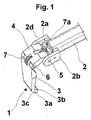
- a tool generally designed with the reference numeral 1, for assembling-disassembling a tyre P, comprising a tool-carrying arm 2 supported in a radial direction with respect to the tyre at one end thereof by means of a side guide 13a provided in a tyre assembling-disassembling machine with respect to which it can translate in a direction substantially parallel to the axis y-y of the tyre in Fig. 11, as further explained below.
- the arm 2 at its other end is fork-shaped and has its tines shaped as two side plates 2a and 2b extending parallel to the arm 2.
- the fork 2 is articulated to a nail-shaped member 3 through a shackle member 4, which, in turn, is articulated to the two side plates 2a and 2b of the fork 2d at one end 5 thereof, and to one end of the nail-shaped member 3 at its other end 6.
- the nail-shaped member 3 is substantially plate-like shaped and has its other (free) end substantially hook-shaped and terminating with a cross length 3a arranged to delimit together with the plate-like portion both an inner recess 3b facing, in use, the tool-carrying arm 2, and an outer groove 3c facing away from the recess 3b.
- a respective resilient contrast spring 7 and 7a is provided between nail-shaped member 3 and shackle member 4, and between the shackle member and tool-carrying arm 2.
- Such springs are suitable for holding the nail-shaped member 3 in a substantially normal trim with respect to arm 2, whereas the shackle member 4 is held substantially aligned with the arm itself, and act as return members after each trim change, as further described below.
- the tool 1 can be made of any suitable material, preferably an anti-friction plastics material, e.g. nylon (registered TM), which is advantageously reinforced with reinforcing fiber or frameworks, e.g. glass fibers.
- an anti-friction plastics material e.g. nylon (registered TM)
- nylon registered TM
- reinforcing fiber or frameworks e.g. glass fibers.
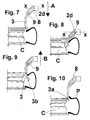
- the tool 1 is caused to abut, at the outer groove 3c of its free end 3a (Fig. 2) against the wheel rim C at a contact area between wheel rim edge and tyre bead by suitably lowering the tool-carrying arm 2; then, while continuing lowering of tool-carrying arm 2 (Fig.
- the end 3a of the nail-shaped member is inserted between bead and tyre edge, until the tyre bead is engaged by the nail at the inner recess 3b of the hook-shaped end 3c (Fig. 4).
- the nail 3 in contact with the wheel rim always still at its outer groove rotates about the pin 6 in a such a direction that the end 3a moves near the wheel rim, whereas the shackle member 4 rotates about the pin 5 in the same direction of rotation as that of the nail, thus changing from a substantially horizontal configuration to a substantially vertical configuration.
- Such a double rotation essentially results in a roto-translational movement of the nail 3 with respect to the tool-carrying arm 2.
- the shackle member 4 is carried to a balance position controlled by the spring 7a with respect to the arm 2, and any further upward movement of the arm 2 will result in the shackle member 4, and consequently the nail 3, being moved upwards, the nail 3 dragging the tyre bead to a position (Fig. 6) in which it is outside the tyre edge, whereas the free end 3a of the nail 3 slidably engages the adjacent edge of the wheel rim at its outer groove 3c.
- a device comprising a tool-carrying arm 2 having its fork-shaped end 2d, in which a pair of opposite slots 8 are formed extending according to a inclined direction (e.g. 45°) with respect to the axis x-x of the tool-carrying arm.
- a pin 9 can freely slide in these slots.
- a nail-shaped member 3 precisely similar that described above has been previously pivoted.
- the arm 2 is caused to move backwards along its guide 13a, whereby a change in the trim of the nail 3 is obtained, the nail taking a trim almost parallel to the axis y-y of the wheel, and, while the backward movement of the arm continues, engaging at the hook-shaped end 3a thereof with the bead inner side until its groove 3c is moved onto the wheel rim edge (Fig. 10), in which position the tyre bead is locally carried outside the wheel rim.
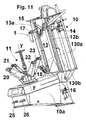
- a self-centering device 11 raises having expansion arms 20 to 23 for rotatably supporting a wheel rim about the axis y-y onto which a tyre is to be assembled, or a tyred wheel from which a respective tyre is to be disassembled.
- the machine 10 is also provided with a pair of bead releasing rollers 17 and 18, one of which 18 is slidably mounted along a guide 13a, the tool-carrying arm 2 being slidable thereon, whereas the other roller 17 is slidably mounted on a guide 13b parallel to the guide 13a, the guides being attached to an upright or rear column 13 of the machine usually provided in an assembling-disassembling machine.
- the tool-carrying arm can be controlled by a double-acting jack 130a, whereas the bead releasing rollers 17 and 18 are controlled to slide along respective sliding guides by means of a respective double-acting jack 130b (only one being shown in Fig. 11).
- rollers are mounted offset with respect to the rotatable self-centering device 11, i.e. they are located on opposite sides with respect to a wheel rim-tyre assembly, as they are slidably mounted on guides 13a and 13b parallel but displaced of a prescribed distance from one another, so as to be located and act, in use, on opposite beads of a tyre, but on opposite sides with respect to the nail 3.
- a control lever 14 is also constrained to the column 13 and provided with a knob carrying a control push-bottom panel and two pedals 25 and 26 arranged in the base, as is known in the art.
- the bead releasing rollers are cantileverwise supported by means of supporting telescopic arms 15 and 16, which automatically expand and contract according to the various diameters of the wheels on which to act.
- an assembling-disassembling device does not require a particularly skilled operator.
- the tool-carrying arm 2 can be telescopic with automatic expansion/contraction movements to be adapted to various tyred-wheel diameters.
Abstract
Description
- The present invention relates to a tool for automatically assembling-disassembling a tyre to/from a wheel rim.
- As it is known, to correctly disassemble a tyre of a tyred wheel from its respective wheel rim, after completion of the required bead releasing operations, it is necessary first to insert an hook-type assembling-disassembling tool into the contact area between tyre and wheel rim, to drive the tool into the contact are, thereby allowing both the tire bead to be spaced from the wheel rim edge and the tool hook to be engaged with the edge of the tyre bead, then to remove the tool, thus dragging with it the edge of the bead until it is extended beyond the wheel-rim edge, and finally to rotate the wheel rim or the tool to progressively force the whole tyre bead beyond the wheel rim edge. Similar and easier operations in reverse sequence must be carried out in order to assemble a tyre.
- Such assembling-disassembling operations require, however, proper accuracy of execution to prevent the wheel rim (which is often made of a light metal alloy) and the tyre from becoming damaged or simply scratched.
- A multiplicity of assembling-disassembling techniques have been suggested and extensive studies and searches have been carried out over time to find a solution to this problem.
- Thus, for example, patent
IT-1 319 475 - Obviously, such a technical solution, on the one hand, is very expensive to be carried out and, on the other, requires a skilled operator in order to avoid damaging the wheel rim and/or the tyre during the assembling-disassembling steps.
- Patent Application No.
US-2004/0 055 712 discloses a particular embodiment of an assembling-disassembling tool fully similar to that described inIT-1 319 475 - Patent
EP-1 459 913 discloses a tyre assembling-disassembling machine provided with a rotatable wheel-carrying table, which can be moved near to, or away from, a rear support upright, and a tyre assembling-disassembling device. The assembling-disassembling device is supported by a sleeve slidable along a guide member parallel to the support upright. An ear of a tool-carrying bush is articulated to the sleeve, the tool being formed by a rod iron with a hook-shaped end which is mounted for rotation in the bush and can be controlled by a double-acting jack so that it can effect angular movements about the axis of the bush. The tool is first moved against to the area between bead and wheel rim edge, with its hook-shaped end being tangentially directed with respect to the wheel rim, it is then driven beyond the tyre edge, the tool is caused to rotate through about 90° to allow the hook-shaped end thereof to climb over and engage with the edge of the tyre bead, and finally a tyre edge portion is extracted and the wheel is subsequently caused to rotate. - Also this assembling-disassembling tool then requires an operation by means of mechanisms controlled by an operator and this, on one hand, results in considerable costs for the tool adjusting and control system, and on the other mistakes are likely to occur owing to a wrong evaluation of the trim (especially the inclination) of the tool with respect to the wheel rim or the tyre, which might result in the tool stumbling in the tyre edge thereby damaging it.
- The main object of the present invention is to provide a tyre assembling-disassembling tool on a tyre assembling-disassembling machine provided with a rotatable support for a tyred wheel or wheel rim, which tool makes it possible to assemble-disassemble a tyre with no manual operations by an operator except the positioning of the wheel onto the rotatable support and the tool adjustment.
- Another object of the present invention is to provide a tyre assembling-disassembling tool very simple to manufacture and use which does not require any dead times as required with manual intervention of the operator, apart from manual intervention during the starting step.
- Another object of the present invention is to provide a tyre assembling-disassembling tool obtainable at competitive production costs.
- According to a first aspect of the present invention, there is provided a tyre assembling-disassembling tool for use with a tyre assembling-disassembling machine arranged rotatably to support a tyred wheel or wheel rim, said tool being supported cantileverwise on a respective guide member of the tyre assembling-disassembling machine, said tool extending parallel to the axis of rotation of the wheel and being characterized in that it comprises a tool-carrying arm which is slidably mounted on said guide member, and at least one nail-shaped member having a first end thereof constrained to said tool-carrying arm, so that it can effect roto-translational movements with respect thereto, and its other free end is hook-shaped and has its back facing said wheel rim.
- Advantageously, at its first end, said nail-shaped member is articulated in at least one recess or slot formed in said tool-carrying arm, said recess or slot extending in an inclined direction with respect to both the axis of the tool-carrying arm and a direction perpendicular thereto.
- Preferably, at said its first end, said nail-shaped member is articulated to an end of a link or shackle member, whose other end is articulated to said tool-carrying arm.
- According to another aspect of the present invention, there is provided a tyre assembling-disassembling machine comprising at least one assembling-disassembling tool as described above.
- Advantageously, such a tyre assembling-disassembling machine also comprises at least one pair of bead-releasing rollers, which are arranged, in use, on opposite sides with respect to a wheel rim or tyred wheel placed on said machine, and uprights sliding parallel to the axis of a wheel rim or tyred wheel, but along two directions parallel and spaced apart a predetermined distance.
- Further features and advantages of the present invention will better appear from the following detailed description of some presently preferred embodiments thereof, given with reference to the accompanying drawings, in which:
- Figure 1 is a perspective view slightly from above which illustrates a tyre assembling-disassembling machine tool according the present invention;
- Figures 2 to 6 show the sequence of the tyre disassembling steps from a wheel rim by means of a tool structured in accordance with a first embodiment thereof;
- Figures 7 to 10 show the sequence of the tyre disassembling steps from a wheel rim by means of a tool structured in accordance with another embodiment thereof; and
- Figure 11 is a perspective side view slightly from below which illustrates a tyre assembling-disassembling machine provided with both a tyre assembling-disassembling tool and a pair of opposite bead-releasing rollers arranged offset with respect to one to another.
- In the accompanying drawings the same or similar parts or components are indicated with the same reference numerals.
- With reference first to Figures 1 to 6 and 11, there is illustrated a tool, generally designed with the
reference numeral 1, for assembling-disassembling a tyre P, comprising a tool-carryingarm 2 supported in a radial direction with respect to the tyre at one end thereof by means of aside guide 13a provided in a tyre assembling-disassembling machine with respect to which it can translate in a direction substantially parallel to the axis y-y of the tyre in Fig. 11, as further explained below. Thearm 2 at its other end is fork-shaped and has its tines shaped as twoside plates arm 2. Moreover, thefork 2 is articulated to a nail-shaped member 3 through ashackle member 4, which, in turn, is articulated to the twoside plates fork 2d at oneend 5 thereof, and to one end of the nail-shaped member 3 at itsother end 6. - The nail-
shaped member 3 is substantially plate-like shaped and has its other (free) end substantially hook-shaped and terminating with across length 3a arranged to delimit together with the plate-like portion both aninner recess 3b facing, in use, the tool-carryingarm 2, and anouter groove 3c facing away from therecess 3b. - A respective
resilient contrast spring shaped member 3 andshackle member 4, and between the shackle member and tool-carryingarm 2. Such springs are suitable for holding the nail-shaped member 3 in a substantially normal trim with respect toarm 2, whereas theshackle member 4 is held substantially aligned with the arm itself, and act as return members after each trim change, as further described below. - The
tool 1 can be made of any suitable material, preferably an anti-friction plastics material, e.g. nylon (registered TM), which is advantageously reinforced with reinforcing fiber or frameworks, e.g. glass fibers. - After the bead of a tyre P has been released, e.g. by means of bead-releasing
rollers tool 1 is caused to abut, at theouter groove 3c of itsfree end 3a (Fig. 2) against the wheel rim C at a contact area between wheel rim edge and tyre bead by suitably lowering the tool-carryingarm 2; then, while continuing lowering of tool-carrying arm 2 (Fig. 3), as shown by arrow A, theend 3a of the nail-shaped member is inserted between bead and tyre edge, until the tyre bead is engaged by the nail at theinner recess 3b of the hook-shaped end 3c (Fig. 4). During these steps, thenail 3 in contact with the wheel rim always still at its outer groove rotates about thepin 6 in a such a direction that theend 3a moves near the wheel rim, whereas theshackle member 4 rotates about thepin 5 in the same direction of rotation as that of the nail, thus changing from a substantially horizontal configuration to a substantially vertical configuration. Such a double rotation essentially results in a roto-translational movement of thenail 3 with respect to the tool-carryingarm 2. - At this point, the tool-carrying
arm 2 is pushed upwards, which results (arrow B, Fig. 5) in the end ofshackle member 4, which is pivoted to the tool-carryingarm 2, being rotated and lifted, and in the end ofshackle member 4, which is pivoted tonail 3, being caused to rotate and translate. As a consequence of these movements, thenail 3, on one hand, pivoted to theshackle member 4 and, on the other, in contact with the wheel rim edge is caused to perform one rotation in such a direction as to cause theend 3a to move away from the wheel rim and to reach again a position substantially parallel to the axis y-y of wheel. - Thus, while continuing to move the
arm 2 upwards, theshackle member 4 is carried to a balance position controlled by thespring 7a with respect to thearm 2, and any further upward movement of thearm 2 will result in theshackle member 4, and consequently thenail 3, being moved upwards, thenail 3 dragging the tyre bead to a position (Fig. 6) in which it is outside the tyre edge, whereas thefree end 3a of thenail 3 slidably engages the adjacent edge of the wheel rim at itsouter groove 3c. - At this point, it will be sufficient to cause the wheel rim or the
tool 1 to rotate, thereby carrying the whole tyre bead above the wheel rim. - With reference now to the embodiment illustrated in Figures 7 to 10, there is shown a device according to the present invention, comprising a tool-carrying
arm 2 having its fork-shaped end 2d, in which a pair ofopposite slots 8 are formed extending according to a inclined direction (e.g. 45°) with respect to the axis x-x of the tool-carrying arm. Apin 9 can freely slide in these slots. To such a pin a nail-shaped member 3 precisely similar that described above has been previously pivoted. - The operation of such a tool is similar to that described with reference to Figures 1 to 6, as the tool-carrying
arm 2, during its downward movement, moves thenail 3 in contact with the wheel rim at the contact area between the wheel rim-tyre and theouter groove 3c of thehook end 3a in contact with the wheel rim, then any further downward movement of thearm 2 causes thenail 3 to become inserted between tyre bead and tyre edge and at the same time it is inclined in a direction in which itsend 3a comes nearer to the inner central band of the wheel rim owing to the sliding movement of thepin 9 along the inclined slots 8 (Fig. 8). - At this point, the
arm 2 is caused to move backwards along itsguide 13a, whereby a change in the trim of thenail 3 is obtained, the nail taking a trim almost parallel to the axis y-y of the wheel, and, while the backward movement of the arm continues, engaging at the hook-shaped end 3a thereof with the bead inner side until itsgroove 3c is moved onto the wheel rim edge (Fig. 10), in which position the tyre bead is locally carried outside the wheel rim. - To complete the tyre disassembling, it is then sufficient to set the wheel or the tool in rotation.
- With specific reference to the tyre assembling-disassembling
machine 10 in Figure 11 provided with the above describedtool 1, it will be noted that from a base generally indicated at 10a a self-centering device 11 raises havingexpansion arms 20 to 23 for rotatably supporting a wheel rim about the axis y-y onto which a tyre is to be assembled, or a tyred wheel from which a respective tyre is to be disassembled. Themachine 10 is also provided with a pair ofbead releasing rollers guide 13a, the tool-carryingarm 2 being slidable thereon, whereas theother roller 17 is slidably mounted on aguide 13b parallel to theguide 13a, the guides being attached to an upright orrear column 13 of the machine usually provided in an assembling-disassembling machine. - It will be noted that the tool-carrying arm can be controlled by a double-acting
jack 130a, whereas thebead releasing rollers jack 130b (only one being shown in Fig. 11). - The specific characteristic of the bead releasing
roller system centering device 11, i.e. they are located on opposite sides with respect to a wheel rim-tyre assembly, as they are slidably mounted onguides nail 3. - A
control lever 14 is also constrained to thecolumn 13 and provided with a knob carrying a control push-bottom panel and twopedals - Advantageously, the bead releasing rollers are cantileverwise supported by means of supporting
telescopic arms - An assembling operation of a tyre onto a wheel rim is carried out in a similar way partly acting in reverse order.
- Thus, an assembling-disassembling device according to the present invention does not require a particularly skilled operator. As a matter of fact, it is sufficient for the operator to place the tyre onto the machine and then adjust the tool-carrying arm so that the tool is placed just above the contact area between tyre and wheel rim and the
outer groove 3c is located at the wheel rim edge. At this point, it is sufficient to control the tool-carrying arm to move downwards until the nail engages with the tyre bead at the inner recess, then to control the tool-carrying arm to move upwards to carry the tyre bead above the wheel rim edge. All these operations can be carried out in a completely automatic way by means of a suitable software and a programmable control unit that can be located either in the base or the column of the machine. - Thus, it is not necessary to control the inclination of
nail 3 during the various disassembling steps, which makes it possible a safely and rapid disassembling without damaging the wheel rim or the tyre, by carrying out roto-translational and inclined movements imposed by the specific tool construction. During all the steps required for disassembling a tyre, thenail 3 remains in contact with a tyre portion at theouter groove 3c and the inclination of theend 3a in the direction of approaching the wheel rim required for thenail 3 to engage the tyre bead occurs automatically through a roto-translation movement of thenail 3 with respect to the tool-carrying arm, as shown in the embodiment of Figs. 2 to 6, where such a roto-translation movement is assured by rotation of theshackle member 4 and rotation and translation of the nail. In the embodiment of Figs. 7 to 10 this is achieved through a translation movement of thepin 9 inside theslot 8, and consequent rotation of the nail and approach of theend 3a to the end of the tool-carryingarm 2. - The tyre assembling-disassembling tool, as well as the tyre assembling-disassembling machine as described above are susceptible of numerous modifications and changes within the scope as defined by the claims.
- Thus for example the tool-carrying
arm 2 can be telescopic with automatic expansion/contraction movements to be adapted to various tyred-wheel diameters.
Claims (15)
- A tyre assembling-disassembling tool for use with a tyre assembling-disassembling machine arranged to rotatably support a tyred wheel or wheel rim, said tool being cantileverwise supported on a respective guide member (13a) of the tyre assembling-disassembling machine, said tool extending parallel to the axis of rotation of the wheel (y-y), and being characterized in that it comprises a tool-carrying arm (2) which is slidably mounted on said guide member (13a), and at least one nail-shaped member (3) having a first end thereof constrained to said supporting arm, thereby being capable of carry out roto-translational movements with respect thereto, and its other free hook-shaped end (3a) provided with a back facing said wheel rim.
- A tool as claimed in claim 1, characterized in that it comprises resiliently yielding contrast means (7, 7a) between said tool-carrying arm (2) and said nail-shaped member (3).
- A tool as claimed in claim 1 or 2, characterized in that, said nail-shaped member (3) is articulated at said first end thereof within at least one recess or slot (8) formed in said tool-carrying arm (2).
- A tool as claimed in claim 3, characterized in that said at least one recess or slot (8) extends in a direction inclined with respect to both the axis (x-x) of said tool-carrying arm and a direction perpendicular thereto.
- A tool as claimed in claim 3 or 4, characterized in that said tool-carrying arm (2) is supported by said guide member at one end thereof, and terminates at its other end (2d) with a fork-shaped member for articulated connection to said nail-shaped member (3).
- A tool as claimed in claim 1 or 2, characterized in that said nail-shaped member (3) at said first end thereof is articulated to an end of a shackle member (4), whose other end is articulated to said tool-carrying arm (2).
- A tool as claimed in claim 6, characterized in that said resiliently yielding means is provided between said nail-shaped member (3) and said shackle member (4), and between said shackle member (4) and said tool-carrying (2), thereby holding said tool in its rest position oriented substantially parallel to the axis of rotation of said wheel rim.
- A tool as claimed in claim 7, characterized in that said resiliently yielding means comprises at least one spring (7, 7a).
- A tool as claimed in any claim 6 to 8, characterized in that said tool-carrying arm (2) is cantileverwise supported by said guide member (13a) at one end thereof, whereas at its other end (2d) it terminates with a fork member for articulated connection to said shackle member (4).
- A tool as claimed in any previous claim, characterized in that said free hook-shaped end (3a) of said nail-shaped member (3) terminates with a transversal length suitable for delimitating an inner recess (3b) facing, in use, said tool-carrying arm, and an outer groove (3c) facing away from said recess.
- A tool as claimed in claim 10, characterised in that said inner recess (3b) is designed to engage and extract, in use, an edge of a tyre bead from a respective wheel rim.
- A tool as claimed in claim 10 or 11, characterized in that said outer groove (3c) is designed to slidably rest on a wheel rim edge.
- A tool as claimed in any previous claim, characterized in that it is made of a suitable anti-friction plastics material.
- A tyre assembling-disassembling machine, characterized in that it comprises at least a slidable tool-carrying arm with its respective tool according to any previous claim.
- A tyre assembling-disassembling machine as claimed in claim 15, characterized in that it comprises at least one pair of bead-releasing rollers (17, 18) arranged, in use, on opposite sides with respect to a wheel rim or tyred wheel placed on said machine, and uprights which slide parallel to the axis of rotation (y-y) of said wheel rim or tyred wheel along two directions parallel to, and spaced from, one another of a predetermined distance.
Applications Claiming Priority (1)
| Application Number | Priority Date | Filing Date | Title |
|---|---|---|---|
| IT000037A ITVR20050037A1 (en) | 2005-03-23 | 2005-03-23 | TOOL FOR AUTOMATIC ASSEMBLY / DISASSEMBLY OF A TIRE ON / FROM A RIM |
Publications (3)
| Publication Number | Publication Date |
|---|---|
| EP1714807A1 true EP1714807A1 (en) | 2006-10-25 |
| EP1714807B1 EP1714807B1 (en) | 2009-07-01 |
| EP1714807B2 EP1714807B2 (en) | 2019-03-27 |
Family
ID=36622238
Family Applications (1)
| Application Number | Title | Priority Date | Filing Date |
|---|---|---|---|
| EP06005915.1A Active EP1714807B2 (en) | 2005-03-23 | 2006-03-23 | Tool for automatically assembling or disassembling a tyre to/from a wheel rim |
Country Status (8)
| Country | Link |
|---|---|
| US (1) | US7497761B2 (en) |
| EP (1) | EP1714807B2 (en) |
| JP (1) | JP4836247B2 (en) |
| CN (1) | CN1935540B (en) |
| AT (1) | ATE435130T1 (en) |
| DE (1) | DE602006007513D1 (en) |
| ES (1) | ES2329067T5 (en) |
| IT (1) | ITVR20050037A1 (en) |
Cited By (16)
| Publication number | Priority date | Publication date | Assignee | Title |
|---|---|---|---|---|
| EP1944177A1 (en) * | 2007-01-15 | 2008-07-16 | Snap-on Equipment Srl a unico socio. | Device for mounting or dismounting a pneumatic tyre from the rim of a vehicle wheel |
| EP2113403A1 (en) | 2008-04-28 | 2009-11-04 | Butler Engineering & Marketing S.p.A. | A bead breaker group for a tire mounting-demounting machine |
| WO2009138322A1 (en) * | 2008-05-15 | 2009-11-19 | Corghi S.P.A. | A tyre-removing method and a tyre-changing machine |
| ITBO20080540A1 (en) * | 2008-09-08 | 2010-03-09 | M & B Engineering S R L | TIRE ASSEMBLY AND DISASSEMBLY |
| CN101934689A (en) * | 2009-06-30 | 2011-01-05 | 小野谷机工株式会社 | Bead detaching arm, tire demounting method and apparatus using bead detaching arm |
| ITBO20120189A1 (en) * | 2012-04-11 | 2013-10-12 | Corghi Spa | DISASSEMBLY TOOL FOR A TIRE CHANGER MACHINE AND TIRE DISASSEMBLER |
| EP2692553A1 (en) | 2012-08-01 | 2014-02-05 | Butler Engineering & Marketing Spa | A device for disassembling a tyre from a wheel rim and a method of disassembling a tyred wheel. |
| ITBO20130523A1 (en) * | 2013-09-25 | 2015-03-26 | Corghi Spa | TOOL FOR DISASSEMBLY OF A TIRE AND TIRE DISMANTLING MACHINE |
| ITVR20130252A1 (en) * | 2013-11-22 | 2015-05-23 | Butler Engineering And Marketing S P A | DISASSEMBLY DEVICE FOR A WHEELED WHEEL, AS WELL AS THE MACHINE INCLUDING THIS DEVICE. |
| EP2949488A1 (en) | 2014-05-30 | 2015-12-02 | Snap-on Equipment Srl a unico socio | Mounting/demounting tool unit with preloaded tool |
| EP2949486A1 (en) | 2014-05-30 | 2015-12-02 | Snap-on Equipment Srl a unico socio | Method for mounting and demounting a tyre to and from a wheel rim |
| CN105291727A (en) * | 2014-07-28 | 2016-02-03 | 巴特勒工程商用股份公司 | Device for assembling-disassembling a tyred wheel, as well as machine comprising such a device |
| DE202014008932U1 (en) | 2014-11-11 | 2016-03-02 | Snap-On Equipment Srl A Unico Socio | Tire mounting and dismounting tool |
| EP3266628A1 (en) | 2016-07-08 | 2018-01-10 | Butler Engineering & Marketing S.p.A. | Group for bead releasing a tyred wheel and machine for mounting or demounting a tyre |
| IT201900019864A1 (en) * | 2019-10-28 | 2021-04-28 | Beissbarth Gmbh | TIRE CHANGING MACHINE |
| IT202100006998A1 (en) * | 2021-03-23 | 2022-09-23 | Nexion Spa | WORKING TOOL FOR A TIRE CHANGER APPARATUS |
Families Citing this family (18)
| Publication number | Priority date | Publication date | Assignee | Title |
|---|---|---|---|---|
| US7975579B1 (en) * | 2007-04-24 | 2011-07-12 | Eagle International, Llc | System and method for cutting tires |
| ITMO20070350A1 (en) * | 2007-11-21 | 2009-05-22 | Giuliano Spa | MACHINE FOR ASSEMBLY AND DISASSEMBLY OF WHEEL TIRES FOR VEHICLES |
| JP2009227006A (en) * | 2008-03-19 | 2009-10-08 | Onodani Kiko Kk | Tire bead guide device for tire mounting/demounting apparatus |
| JP5026477B2 (en) * | 2009-07-30 | 2012-09-12 | 小野谷機工株式会社 | Method and apparatus for removing tire bead |
| JP5026481B2 (en) * | 2009-08-22 | 2012-09-12 | 小野谷機工株式会社 | Tire attaching / detaching device with rotating table |
| JP5026473B2 (en) * | 2009-06-30 | 2012-09-12 | 小野谷機工株式会社 | How to remove the bead on the tire |
| US8136567B2 (en) * | 2009-11-24 | 2012-03-20 | Aymar Brandon P | Car tire attachment mechanism |
| FR2957417B1 (en) * | 2010-03-15 | 2013-01-04 | Michelin Soc Tech | HOLDING DEVICE FOR VISUAL INSPECTION OF A TIRE |
| US8973640B1 (en) | 2010-12-07 | 2015-03-10 | Hunter Engineering Company | Demount tool assembly and methods for automated tire changer machine |
| IT1403058B1 (en) * | 2010-12-09 | 2013-09-27 | Butler Eng & Marketing | DEVICE FOR DISASSEMBLING A TIRE FROM A RIM AND AS A DISASSEMBLER MACHINE EQUIPPED WITH SUCH A DEVICE |
| CA2826851C (en) * | 2011-02-11 | 2019-03-19 | Austin Engineering Ltd | Article handling apparatus |
| JP2014528381A (en) * | 2011-10-06 | 2014-10-27 | ブリヂストン アメリカズ タイヤ オペレイションズ エルエルシー | Method and apparatus for mounting tires |
| ITMO20120009A1 (en) * | 2012-01-16 | 2013-07-17 | Gino Ferrari | EXTRACTOR DEVICE FOR REMOVAL MACHINES |
| US11001108B2 (en) * | 2014-05-30 | 2021-05-11 | Snap-On Equipment Srl A Unico Socio | Mounting/demounting tool unit with preloaded tool |
| CN104527344B (en) * | 2014-12-29 | 2017-01-11 | 营口光明科技有限公司 | Tire bead separator arranged on manipulator of tire changer |
| WO2016136972A1 (en) * | 2015-02-28 | 2016-09-01 | 株式会社シーパーツ | Tire-gripping head, and tire-mounting/removing robot and tire-mounting/removing system which include same |
| EP3828014B1 (en) | 2019-11-27 | 2023-06-28 | CEMB S.p.A. | Device for mounting and removing a tire on and from a rim |
| CN115416434B (en) * | 2022-09-19 | 2023-11-14 | 伺轮智能机器人(南京)有限公司 | Self-adaptation tire dismouting manipulator |
Citations (4)
| Publication number | Priority date | Publication date | Assignee | Title |
|---|---|---|---|---|
| EP1314584A1 (en) * | 2001-11-22 | 2003-05-28 | BUTLER ENGINEERING & MARKETING S.r.l. | Bead releasing and removing head for a tire-fitting machine |
| IT1319475B1 (en) | 2000-08-03 | 2003-10-10 | Corghi Spa | AUTOMATIC DEVICE FOR DISASSEMBLY AND ASSEMBLY OF PNEUMATICS, AND TIRE CHANGER MACHINES SO EQUIPPED |
| US20040055712A1 (en) | 2002-09-13 | 2004-03-25 | Corghi S.P.A. | Simplified automatic tyre demounting device, and tyre removal machines equipped therewith |
| EP1593533A2 (en) * | 2004-05-06 | 2005-11-09 | CORGHI S.p.A. | Automatic device for mounting and dismounting tires |
Family Cites Families (5)
| Publication number | Priority date | Publication date | Assignee | Title |
|---|---|---|---|---|
| CH399214A (en) * | 1963-10-15 | 1966-03-31 | Furrer Ferdinand | Apparatus for removing tires from vehicle wheels |
| JP3626088B2 (en) * | 2000-11-09 | 2005-03-02 | 小野谷機工株式会社 | Automobile tire removing method and tire removing device |
| JP2003320828A (en) * | 2002-04-30 | 2003-11-11 | Takeuchi Giken Seisakusho:Goushi | Tire mounting/dismounting device and method for tubeless tire |
| ITMO20030084A1 (en) * | 2003-03-21 | 2004-09-22 | Snap On Equipment Srl A Socio Unico | DEVICE FOR MONITORING AND DISASSEMBLING TIRES OF WHEELS POSITIONED ON WHEEL HOLDER TABLES OF TIRE CHANGERS. |
| ITMO20030132A1 (en) * | 2003-05-09 | 2004-11-10 | Giuliano Srl | MACHINE FOR THE ASSEMBLY AND DISASSEMBLY OF TIRES AND WHEEL RIMS FOR VEHICLES. |
-
2005
- 2005-03-23 IT IT000037A patent/ITVR20050037A1/en unknown
-
2006
- 2006-03-22 US US11/386,517 patent/US7497761B2/en active Active
- 2006-03-23 DE DE602006007513T patent/DE602006007513D1/en active Active
- 2006-03-23 EP EP06005915.1A patent/EP1714807B2/en active Active
- 2006-03-23 CN CN2006100718900A patent/CN1935540B/en active Active
- 2006-03-23 AT AT06005915T patent/ATE435130T1/en not_active IP Right Cessation
- 2006-03-23 ES ES06005915T patent/ES2329067T5/en active Active
- 2006-03-23 JP JP2006081122A patent/JP4836247B2/en active Active
Patent Citations (4)
| Publication number | Priority date | Publication date | Assignee | Title |
|---|---|---|---|---|
| IT1319475B1 (en) | 2000-08-03 | 2003-10-10 | Corghi Spa | AUTOMATIC DEVICE FOR DISASSEMBLY AND ASSEMBLY OF PNEUMATICS, AND TIRE CHANGER MACHINES SO EQUIPPED |
| EP1314584A1 (en) * | 2001-11-22 | 2003-05-28 | BUTLER ENGINEERING & MARKETING S.r.l. | Bead releasing and removing head for a tire-fitting machine |
| US20040055712A1 (en) | 2002-09-13 | 2004-03-25 | Corghi S.P.A. | Simplified automatic tyre demounting device, and tyre removal machines equipped therewith |
| EP1593533A2 (en) * | 2004-05-06 | 2005-11-09 | CORGHI S.p.A. | Automatic device for mounting and dismounting tires |
Cited By (34)
| Publication number | Priority date | Publication date | Assignee | Title |
|---|---|---|---|---|
| EP1944177A1 (en) * | 2007-01-15 | 2008-07-16 | Snap-on Equipment Srl a unico socio. | Device for mounting or dismounting a pneumatic tyre from the rim of a vehicle wheel |
| US7743812B2 (en) | 2007-01-15 | 2010-06-29 | Snap-On Equipment Srl A Unico Socio | Apparatus for fitting or removing a pneumatic tire to or from a rim of a vehicle wheel |
| CN101234586B (en) * | 2007-01-15 | 2013-05-29 | 施耐宝仪器股份有限公司 | Apparatus for fitting or removing a pneumatic tyre to or from a rim of a vehicle wheel |
| EP2113403A1 (en) | 2008-04-28 | 2009-11-04 | Butler Engineering & Marketing S.p.A. | A bead breaker group for a tire mounting-demounting machine |
| US8464774B2 (en) | 2008-04-28 | 2013-06-18 | Butler Engineering & Marketing S.P.A. | Bead breaker group for a tire mounting-demounting machine |
| WO2009138322A1 (en) * | 2008-05-15 | 2009-11-19 | Corghi S.P.A. | A tyre-removing method and a tyre-changing machine |
| ITBO20080540A1 (en) * | 2008-09-08 | 2010-03-09 | M & B Engineering S R L | TIRE ASSEMBLY AND DISASSEMBLY |
| WO2010026539A1 (en) * | 2008-09-08 | 2010-03-11 | M&B Engineering S.R.L. | Device for fitting and removing tyres |
| US9090135B2 (en) | 2008-09-08 | 2015-07-28 | M&B Engineering S.R.L. | Device for fitting and removing tyres |
| CN101934689A (en) * | 2009-06-30 | 2011-01-05 | 小野谷机工株式会社 | Bead detaching arm, tire demounting method and apparatus using bead detaching arm |
| EP2269841A1 (en) * | 2009-06-30 | 2011-01-05 | Onodani Machine Co., Ltd. | Bead detaching arm, tire demounting method and apparatus using bead detaching arm |
| US9067467B2 (en) | 2012-04-11 | 2015-06-30 | Corghi S.P.A. | Tyre removal tool for a tyre removing machine and a tyre removing machine |
| EP2650147A1 (en) * | 2012-04-11 | 2013-10-16 | CORGHI S.p.A. | A tyre removal tool for a tyre removing machine and a tyre removing machine |
| ITBO20120189A1 (en) * | 2012-04-11 | 2013-10-12 | Corghi Spa | DISASSEMBLY TOOL FOR A TIRE CHANGER MACHINE AND TIRE DISASSEMBLER |
| US10189322B2 (en) | 2012-08-01 | 2019-01-29 | Butler Engineering And Marketing S.P.A. | Device for disassembling a tire from a wheel rim and a method of disassembling a tired wheel |
| EP2692553A1 (en) | 2012-08-01 | 2014-02-05 | Butler Engineering & Marketing Spa | A device for disassembling a tyre from a wheel rim and a method of disassembling a tyred wheel. |
| ITBO20130523A1 (en) * | 2013-09-25 | 2015-03-26 | Corghi Spa | TOOL FOR DISASSEMBLY OF A TIRE AND TIRE DISMANTLING MACHINE |
| US9707810B2 (en) | 2013-11-22 | 2017-07-18 | Butler Engineering And Marketing S.P.A. | Device for demounting a tired wheel as well as a machine including such device |
| EP2875969A1 (en) | 2013-11-22 | 2015-05-27 | Butler Engineering & Marketing S.p.A. | A device for demounting a tired wheel as well as a machine including such device |
| ITVR20130252A1 (en) * | 2013-11-22 | 2015-05-23 | Butler Engineering And Marketing S P A | DISASSEMBLY DEVICE FOR A WHEELED WHEEL, AS WELL AS THE MACHINE INCLUDING THIS DEVICE. |
| EP3501862A1 (en) | 2014-05-30 | 2019-06-26 | Snap-on Equipment Srl a unico socio | Method for mounting and demounting a tyre to and from a wheel rim |
| EP2949486A1 (en) | 2014-05-30 | 2015-12-02 | Snap-on Equipment Srl a unico socio | Method for mounting and demounting a tyre to and from a wheel rim |
| EP2949488A1 (en) | 2014-05-30 | 2015-12-02 | Snap-on Equipment Srl a unico socio | Mounting/demounting tool unit with preloaded tool |
| US11214103B2 (en) | 2014-05-30 | 2022-01-04 | Snap-On Equipment Srl A Unico Socio | Method for mounting and demounting a tyre to and from a wheel rim |
| CN105291727A (en) * | 2014-07-28 | 2016-02-03 | 巴特勒工程商用股份公司 | Device for assembling-disassembling a tyred wheel, as well as machine comprising such a device |
| EP2987661A1 (en) * | 2014-07-28 | 2016-02-24 | Butler Engineering & Marketing S.p.A. | Device for assembling-disassembling a tyred wheel, as well as machine comprising such a device |
| US10065462B2 (en) | 2014-07-28 | 2018-09-04 | Butler Engineering And Marketings S.P.A. | Device for assembling-disassembling a tyred wheel, as well as machine comprising such a device |
| CN105291727B (en) * | 2014-07-28 | 2018-10-19 | 巴特勒工程商用股份公司 | The equipment of wheel of the assembling-dismounting equipped with tire and the machine for including this equipment |
| DE202014008932U1 (en) | 2014-11-11 | 2016-03-02 | Snap-On Equipment Srl A Unico Socio | Tire mounting and dismounting tool |
| US10377193B2 (en) | 2016-07-08 | 2019-08-13 | Butler Engineering And Marketing S.P.A. | Group for bead releasing a tyred wheel and/or for thrusting a portion of a tyre of a tyred wheel |
| EP3266628A1 (en) | 2016-07-08 | 2018-01-10 | Butler Engineering & Marketing S.p.A. | Group for bead releasing a tyred wheel and machine for mounting or demounting a tyre |
| IT201900019864A1 (en) * | 2019-10-28 | 2021-04-28 | Beissbarth Gmbh | TIRE CHANGING MACHINE |
| WO2021084398A1 (en) * | 2019-10-28 | 2021-05-06 | Beissbarth Gmbh | Tyre-changing machine |
| IT202100006998A1 (en) * | 2021-03-23 | 2022-09-23 | Nexion Spa | WORKING TOOL FOR A TIRE CHANGER APPARATUS |
Also Published As
| Publication number | Publication date |
|---|---|
| US7497761B2 (en) | 2009-03-03 |
| ATE435130T1 (en) | 2009-07-15 |
| ES2329067T3 (en) | 2009-11-20 |
| CN1935540B (en) | 2011-06-15 |
| EP1714807B2 (en) | 2019-03-27 |
| DE602006007513D1 (en) | 2009-08-13 |
| JP4836247B2 (en) | 2011-12-14 |
| ES2329067T5 (en) | 2019-12-04 |
| US20060254725A1 (en) | 2006-11-16 |
| CN1935540A (en) | 2007-03-28 |
| ITVR20050037A1 (en) | 2006-09-24 |
| JP2006298360A (en) | 2006-11-02 |
| EP1714807B1 (en) | 2009-07-01 |
Similar Documents
| Publication | Publication Date | Title |
|---|---|---|
| EP1714807B1 (en) | Tool for automatically assembling or disassembling a tyre to/from a wheel rim | |
| JP5651351B2 (en) | Vehicle wheel tire attachment / detachment machine | |
| EP2524821B1 (en) | Device for the automatic demounting of a tire from a rim and machine equipped with such device | |
| US8973640B1 (en) | Demount tool assembly and methods for automated tire changer machine | |
| EP1897709B1 (en) | Machine for fitting and removing vehicle tyres | |
| EP1897710B1 (en) | Improved device for tyre disassembling machines designed to simplify tyre assembling without exessive stretching | |
| EP2629992B1 (en) | A tyre demounting machine | |
| US10065462B2 (en) | Device for assembling-disassembling a tyred wheel, as well as machine comprising such a device | |
| US20120145333A1 (en) | Device for demounting a tire from a rim as well as a tire demounting machine equipped with such device | |
| JP2012240676A5 (en) | ||
| EP2692553B1 (en) | A device for disassembling a tyre from a wheel rim and a method of disassembling a tyred wheel. | |
| JP5404162B2 (en) | Bead breaker group for tire installation / removal machines | |
| US8464775B2 (en) | Tool for tire uninstalling and installing machines | |
| US8746317B2 (en) | Working tool orienting device in tire demounting machine | |
| US7946016B2 (en) | Method and machine for removing a tyre fitted with a rigid inner run-flat ring | |
| CN111016557B (en) | Machine for mounting and/or dismounting vehicle wheels, in particular truck wheels | |
| EP2514610B1 (en) | A lifting apparatus for tyre changing machines | |
| ITBO20130384A1 (en) | DEVICE AND METHOD FOR STALLONING WHEELS EQUIPPED WITH A TIRE PAIRED TO A RIM. |
Legal Events
| Date | Code | Title | Description |
|---|---|---|---|
| PUAI | Public reference made under article 153(3) epc to a published international application that has entered the european phase |
Free format text: ORIGINAL CODE: 0009012 |
|
| AK | Designated contracting states |
Kind code of ref document: A1 Designated state(s): AT BE BG CH CY CZ DE DK EE ES FI FR GB GR HU IE IS IT LI LT LU LV MC NL PL PT RO SE SI SK TR |
|
| AX | Request for extension of the european patent |
Extension state: AL BA HR MK YU |
|
| 17P | Request for examination filed |
Effective date: 20070423 |
|
| AKX | Designation fees paid |
Designated state(s): AT BE BG CH CY CZ DE DK EE ES FI FR GB GR HU IE IS IT LI LT LU LV MC NL PL PT RO SE SI SK TR |
|
| 17Q | First examination report despatched |
Effective date: 20080819 |
|
| GRAP | Despatch of communication of intention to grant a patent |
Free format text: ORIGINAL CODE: EPIDOSNIGR1 |
|
| GRAS | Grant fee paid |
Free format text: ORIGINAL CODE: EPIDOSNIGR3 |
|
| GRAA | (expected) grant |
Free format text: ORIGINAL CODE: 0009210 |
|
| AK | Designated contracting states |
Kind code of ref document: B1 Designated state(s): AT BE BG CH CY CZ DE DK EE ES FI FR GB GR HU IE IS IT LI LT LU LV MC NL PL PT RO SE SI SK TR |
|
| REG | Reference to a national code |
Ref country code: GB Ref legal event code: FG4D |
|
| REG | Reference to a national code |
Ref country code: CH Ref legal event code: EP |
|
| REG | Reference to a national code |
Ref country code: IE Ref legal event code: FG4D |
|
| REF | Corresponds to: |
Ref document number: 602006007513 Country of ref document: DE Date of ref document: 20090813 Kind code of ref document: P |
|
| PLBI | Opposition filed |
Free format text: ORIGINAL CODE: 0009260 |
|
| REG | Reference to a national code |
Ref country code: ES Ref legal event code: FG2A Ref document number: 2329067 Country of ref document: ES Kind code of ref document: T3 |
|
| PG25 | Lapsed in a contracting state [announced via postgrant information from national office to epo] |
Ref country code: SI Free format text: LAPSE BECAUSE OF FAILURE TO SUBMIT A TRANSLATION OF THE DESCRIPTION OR TO PAY THE FEE WITHIN THE PRESCRIBED TIME-LIMIT Effective date: 20090701 |
|
| NLV1 | Nl: lapsed or annulled due to failure to fulfill the requirements of art. 29p and 29m of the patents act | ||
| 26 | Opposition filed |
Opponent name: SNAP-ON EQUIPMENT GMBH Effective date: 20091030 |
|
| PG25 | Lapsed in a contracting state [announced via postgrant information from national office to epo] |
Ref country code: SE Free format text: LAPSE BECAUSE OF FAILURE TO SUBMIT A TRANSLATION OF THE DESCRIPTION OR TO PAY THE FEE WITHIN THE PRESCRIBED TIME-LIMIT Effective date: 20090701 Ref country code: FI Free format text: LAPSE BECAUSE OF FAILURE TO SUBMIT A TRANSLATION OF THE DESCRIPTION OR TO PAY THE FEE WITHIN THE PRESCRIBED TIME-LIMIT Effective date: 20090701 Ref country code: IS Free format text: LAPSE BECAUSE OF FAILURE TO SUBMIT A TRANSLATION OF THE DESCRIPTION OR TO PAY THE FEE WITHIN THE PRESCRIBED TIME-LIMIT Effective date: 20091101 Ref country code: AT Free format text: LAPSE BECAUSE OF FAILURE TO SUBMIT A TRANSLATION OF THE DESCRIPTION OR TO PAY THE FEE WITHIN THE PRESCRIBED TIME-LIMIT Effective date: 20090701 Ref country code: EE Free format text: LAPSE BECAUSE OF FAILURE TO SUBMIT A TRANSLATION OF THE DESCRIPTION OR TO PAY THE FEE WITHIN THE PRESCRIBED TIME-LIMIT Effective date: 20090701 Ref country code: LT Free format text: LAPSE BECAUSE OF FAILURE TO SUBMIT A TRANSLATION OF THE DESCRIPTION OR TO PAY THE FEE WITHIN THE PRESCRIBED TIME-LIMIT Effective date: 20090701 |
|
| PG25 | Lapsed in a contracting state [announced via postgrant information from national office to epo] |
Ref country code: NL Free format text: LAPSE BECAUSE OF FAILURE TO SUBMIT A TRANSLATION OF THE DESCRIPTION OR TO PAY THE FEE WITHIN THE PRESCRIBED TIME-LIMIT Effective date: 20090701 Ref country code: PL Free format text: LAPSE BECAUSE OF FAILURE TO SUBMIT A TRANSLATION OF THE DESCRIPTION OR TO PAY THE FEE WITHIN THE PRESCRIBED TIME-LIMIT Effective date: 20090701 Ref country code: LV Free format text: LAPSE BECAUSE OF FAILURE TO SUBMIT A TRANSLATION OF THE DESCRIPTION OR TO PAY THE FEE WITHIN THE PRESCRIBED TIME-LIMIT Effective date: 20090701 |
|
| PG25 | Lapsed in a contracting state [announced via postgrant information from national office to epo] |
Ref country code: PT Free format text: LAPSE BECAUSE OF FAILURE TO SUBMIT A TRANSLATION OF THE DESCRIPTION OR TO PAY THE FEE WITHIN THE PRESCRIBED TIME-LIMIT Effective date: 20091102 Ref country code: BG Free format text: LAPSE BECAUSE OF FAILURE TO SUBMIT A TRANSLATION OF THE DESCRIPTION OR TO PAY THE FEE WITHIN THE PRESCRIBED TIME-LIMIT Effective date: 20091001 |
|
| PG25 | Lapsed in a contracting state [announced via postgrant information from national office to epo] |
Ref country code: RO Free format text: LAPSE BECAUSE OF FAILURE TO SUBMIT A TRANSLATION OF THE DESCRIPTION OR TO PAY THE FEE WITHIN THE PRESCRIBED TIME-LIMIT Effective date: 20090701 Ref country code: CZ Free format text: LAPSE BECAUSE OF FAILURE TO SUBMIT A TRANSLATION OF THE DESCRIPTION OR TO PAY THE FEE WITHIN THE PRESCRIBED TIME-LIMIT Effective date: 20090701 Ref country code: DK Free format text: LAPSE BECAUSE OF FAILURE TO SUBMIT A TRANSLATION OF THE DESCRIPTION OR TO PAY THE FEE WITHIN THE PRESCRIBED TIME-LIMIT Effective date: 20090701 |
|
| PLAX | Notice of opposition and request to file observation + time limit sent |
Free format text: ORIGINAL CODE: EPIDOSNOBS2 |
|
| PG25 | Lapsed in a contracting state [announced via postgrant information from national office to epo] |
Ref country code: SK Free format text: LAPSE BECAUSE OF FAILURE TO SUBMIT A TRANSLATION OF THE DESCRIPTION OR TO PAY THE FEE WITHIN THE PRESCRIBED TIME-LIMIT Effective date: 20090701 Ref country code: BE Free format text: LAPSE BECAUSE OF FAILURE TO SUBMIT A TRANSLATION OF THE DESCRIPTION OR TO PAY THE FEE WITHIN THE PRESCRIBED TIME-LIMIT Effective date: 20090701 |
|
| PLBB | Reply of patent proprietor to notice(s) of opposition received |
Free format text: ORIGINAL CODE: EPIDOSNOBS3 |
|
| PG25 | Lapsed in a contracting state [announced via postgrant information from national office to epo] |
Ref country code: GR Free format text: LAPSE BECAUSE OF FAILURE TO SUBMIT A TRANSLATION OF THE DESCRIPTION OR TO PAY THE FEE WITHIN THE PRESCRIBED TIME-LIMIT Effective date: 20091002 Ref country code: MC Free format text: LAPSE BECAUSE OF NON-PAYMENT OF DUE FEES Effective date: 20100331 |
|
| REG | Reference to a national code |
Ref country code: CH Ref legal event code: PL |
|
| GBPC | Gb: european patent ceased through non-payment of renewal fee |
Effective date: 20100323 |
|
| PG25 | Lapsed in a contracting state [announced via postgrant information from national office to epo] |
Ref country code: IE Free format text: LAPSE BECAUSE OF NON-PAYMENT OF DUE FEES Effective date: 20100323 |
|
| PG25 | Lapsed in a contracting state [announced via postgrant information from national office to epo] |
Ref country code: CH Free format text: LAPSE BECAUSE OF NON-PAYMENT OF DUE FEES Effective date: 20100331 Ref country code: LI Free format text: LAPSE BECAUSE OF NON-PAYMENT OF DUE FEES Effective date: 20100331 |
|
| PG25 | Lapsed in a contracting state [announced via postgrant information from national office to epo] |
Ref country code: GB Free format text: LAPSE BECAUSE OF NON-PAYMENT OF DUE FEES Effective date: 20100323 |
|
| PG25 | Lapsed in a contracting state [announced via postgrant information from national office to epo] |
Ref country code: CY Free format text: LAPSE BECAUSE OF FAILURE TO SUBMIT A TRANSLATION OF THE DESCRIPTION OR TO PAY THE FEE WITHIN THE PRESCRIBED TIME-LIMIT Effective date: 20090701 |
|
| PG25 | Lapsed in a contracting state [announced via postgrant information from national office to epo] |
Ref country code: LU Free format text: LAPSE BECAUSE OF NON-PAYMENT OF DUE FEES Effective date: 20100323 Ref country code: HU Free format text: LAPSE BECAUSE OF FAILURE TO SUBMIT A TRANSLATION OF THE DESCRIPTION OR TO PAY THE FEE WITHIN THE PRESCRIBED TIME-LIMIT Effective date: 20100102 |
|
| PG25 | Lapsed in a contracting state [announced via postgrant information from national office to epo] |
Ref country code: TR Free format text: LAPSE BECAUSE OF FAILURE TO SUBMIT A TRANSLATION OF THE DESCRIPTION OR TO PAY THE FEE WITHIN THE PRESCRIBED TIME-LIMIT Effective date: 20090701 |
|
| RAP2 | Party data changed (patent owner data changed or rights of a patent transferred) |
Owner name: BUTLER ENGINEERING & MARKETING S.P.A. |
|
| APBM | Appeal reference recorded |
Free format text: ORIGINAL CODE: EPIDOSNREFNO |
|
| APBP | Date of receipt of notice of appeal recorded |
Free format text: ORIGINAL CODE: EPIDOSNNOA2O |
|
| APAH | Appeal reference modified |
Free format text: ORIGINAL CODE: EPIDOSCREFNO |
|
| APBQ | Date of receipt of statement of grounds of appeal recorded |
Free format text: ORIGINAL CODE: EPIDOSNNOA3O |
|
| APAW | Appeal reference deleted |
Free format text: ORIGINAL CODE: EPIDOSDREFNO |
|
| APBQ | Date of receipt of statement of grounds of appeal recorded |
Free format text: ORIGINAL CODE: EPIDOSNNOA3O |
|
| REG | Reference to a national code |
Ref country code: FR Ref legal event code: PLFP Year of fee payment: 11 |
|
| APAH | Appeal reference modified |
Free format text: ORIGINAL CODE: EPIDOSCREFNO |
|
| REG | Reference to a national code |
Ref country code: FR Ref legal event code: PLFP Year of fee payment: 12 |
|
| APBU | Appeal procedure closed |
Free format text: ORIGINAL CODE: EPIDOSNNOA9O |
|
| PLAY | Examination report in opposition despatched + time limit |
Free format text: ORIGINAL CODE: EPIDOSNORE2 |
|
| PLBC | Reply to examination report in opposition received |
Free format text: ORIGINAL CODE: EPIDOSNORE3 |
|
| REG | Reference to a national code |
Ref country code: FR Ref legal event code: PLFP Year of fee payment: 13 |
|
| RIC2 | Information provided on ipc code assigned after grant |
Ipc: B60C 25/138 20060101ALI20180626BHEP Ipc: B60C 25/05 20060101AFI20180626BHEP |
|
| PUAH | Patent maintained in amended form |
Free format text: ORIGINAL CODE: 0009272 |
|
| STAA | Information on the status of an ep patent application or granted ep patent |
Free format text: STATUS: PATENT MAINTAINED AS AMENDED |
|
| 27A | Patent maintained in amended form |
Effective date: 20190327 |
|
| AK | Designated contracting states |
Kind code of ref document: B2 Designated state(s): AT BE BG CH CY CZ DE DK EE ES FI FR GB GR HU IE IS IT LI LT LU LV MC NL PL PT RO SE SI SK TR |
|
| REG | Reference to a national code |
Ref country code: DE Ref legal event code: R102 Ref document number: 602006007513 Country of ref document: DE |
|
| REG | Reference to a national code |
Ref country code: ES Ref legal event code: DC2A Ref document number: 2329067 Country of ref document: ES Kind code of ref document: T5 Effective date: 20191204 |
|
| PGFP | Annual fee paid to national office [announced via postgrant information from national office to epo] |
Ref country code: FR Payment date: 20230323 Year of fee payment: 18 |
|
| PGFP | Annual fee paid to national office [announced via postgrant information from national office to epo] |
Ref country code: IT Payment date: 20230321 Year of fee payment: 18 Ref country code: DE Payment date: 20230328 Year of fee payment: 18 |
|
| P01 | Opt-out of the competence of the unified patent court (upc) registered |
Effective date: 20230515 |
|
| PGFP | Annual fee paid to national office [announced via postgrant information from national office to epo] |
Ref country code: ES Payment date: 20230424 Year of fee payment: 18 |