EP2692553A1 - A device for disassembling a tyre from a wheel rim and a method of disassembling a tyred wheel. - Google Patents
A device for disassembling a tyre from a wheel rim and a method of disassembling a tyred wheel. Download PDFInfo
- Publication number
- EP2692553A1 EP2692553A1 EP13176457.3A EP13176457A EP2692553A1 EP 2692553 A1 EP2692553 A1 EP 2692553A1 EP 13176457 A EP13176457 A EP 13176457A EP 2692553 A1 EP2692553 A1 EP 2692553A1
- Authority
- EP
- European Patent Office
- Prior art keywords
- tool
- disassembling
- wheel rim
- support member
- tyre
- Prior art date
- Legal status (The legal status is an assumption and is not a legal conclusion. Google has not performed a legal analysis and makes no representation as to the accuracy of the status listed.)
- Granted
Links
- 238000000034 method Methods 0.000 title claims description 13
- 238000000605 extraction Methods 0.000 claims abstract description 34
- 239000011324 bead Substances 0.000 claims description 45
- 238000003780 insertion Methods 0.000 claims description 22
- 230000037431 insertion Effects 0.000 claims description 22
- 238000006243 chemical reaction Methods 0.000 claims description 7
- 230000001960 triggered effect Effects 0.000 claims description 2
- 238000006073 displacement reaction Methods 0.000 claims 1
- 238000013519 translation Methods 0.000 description 3
- 230000000694 effects Effects 0.000 description 2
- 238000013459 approach Methods 0.000 description 1
- 238000004880 explosion Methods 0.000 description 1
- 238000004519 manufacturing process Methods 0.000 description 1
- 238000012986 modification Methods 0.000 description 1
- 230000004048 modification Effects 0.000 description 1
- 230000000630 rising effect Effects 0.000 description 1
Images


Classifications
-
- B—PERFORMING OPERATIONS; TRANSPORTING
- B60—VEHICLES IN GENERAL
- B60C—VEHICLE TYRES; TYRE INFLATION; TYRE CHANGING; CONNECTING VALVES TO INFLATABLE ELASTIC BODIES IN GENERAL; DEVICES OR ARRANGEMENTS RELATED TO TYRES
- B60C25/00—Apparatus or tools adapted for mounting, removing or inspecting tyres
- B60C25/01—Apparatus or tools adapted for mounting, removing or inspecting tyres for removing tyres from or mounting tyres on wheels
- B60C25/05—Machines
- B60C25/0563—Tools interacting with the tyre and moved in relation to the tyre during operation
-
- B—PERFORMING OPERATIONS; TRANSPORTING
- B60—VEHICLES IN GENERAL
- B60C—VEHICLE TYRES; TYRE INFLATION; TYRE CHANGING; CONNECTING VALVES TO INFLATABLE ELASTIC BODIES IN GENERAL; DEVICES OR ARRANGEMENTS RELATED TO TYRES
- B60C25/00—Apparatus or tools adapted for mounting, removing or inspecting tyres
- B60C25/01—Apparatus or tools adapted for mounting, removing or inspecting tyres for removing tyres from or mounting tyres on wheels
- B60C25/05—Machines
- B60C25/0524—Separating tyres from rims, e.g. by destroying
-
- B—PERFORMING OPERATIONS; TRANSPORTING
- B60—VEHICLES IN GENERAL
- B60C—VEHICLE TYRES; TYRE INFLATION; TYRE CHANGING; CONNECTING VALVES TO INFLATABLE ELASTIC BODIES IN GENERAL; DEVICES OR ARRANGEMENTS RELATED TO TYRES
- B60C25/00—Apparatus or tools adapted for mounting, removing or inspecting tyres
- B60C25/01—Apparatus or tools adapted for mounting, removing or inspecting tyres for removing tyres from or mounting tyres on wheels
- B60C25/05—Machines
- B60C25/0506—Machines for demounting only
-
- B—PERFORMING OPERATIONS; TRANSPORTING
- B60—VEHICLES IN GENERAL
- B60C—VEHICLE TYRES; TYRE INFLATION; TYRE CHANGING; CONNECTING VALVES TO INFLATABLE ELASTIC BODIES IN GENERAL; DEVICES OR ARRANGEMENTS RELATED TO TYRES
- B60C25/00—Apparatus or tools adapted for mounting, removing or inspecting tyres
- B60C25/01—Apparatus or tools adapted for mounting, removing or inspecting tyres for removing tyres from or mounting tyres on wheels
- B60C25/05—Machines
- B60C25/0563—Tools interacting with the tyre and moved in relation to the tyre during operation
- B60C25/0578—Tools interacting with the tyre and moved in relation to the tyre during operation hooking only
-
- B—PERFORMING OPERATIONS; TRANSPORTING
- B60—VEHICLES IN GENERAL
- B60C—VEHICLE TYRES; TYRE INFLATION; TYRE CHANGING; CONNECTING VALVES TO INFLATABLE ELASTIC BODIES IN GENERAL; DEVICES OR ARRANGEMENTS RELATED TO TYRES
- B60C25/00—Apparatus or tools adapted for mounting, removing or inspecting tyres
- B60C25/01—Apparatus or tools adapted for mounting, removing or inspecting tyres for removing tyres from or mounting tyres on wheels
- B60C25/05—Machines
- B60C25/0563—Tools interacting with the tyre and moved in relation to the tyre during operation
- B60C25/0593—Multi-functional tools for performing at least two operations, e.g. bead breaking and bead seeking
Definitions
- the present invention relates to a tyre disassembling device, and a method of disassembling a tyred wheel, more particularly a wheel of relatively large dimensions, e. g. a lorry or truck wheel.
- EP-1 177 920 teaches a machine for assembling and disassembling a tyre onto and from a wheel rim, that comprises a base on which a wheel bearing table is mounted for rotation and from which a column extends upwards at the rear side of the base.
- Parallel straight guides are provided on the column that are substantially vertical, in use, and on which a device for assembling and disassembling a tyre onto and from a wheel rim is slidably mounted.
- a device for assembling and disassembling a tyre onto and from a wheel rim is slidably mounted.
- Such a device comprises a carriage that is slidably mounted along the guides and bears a sleeve having a substantially horizontal axis which supports one end of a hollow shaft that overhangingly extends from the sleeve.
- the hollow shaft at its end secured to the sleeve abuts against one end of the cylinder of a cylinder-and-piston jack, whereas at its other end or distal end it supports a hollow head having an inner opening larger in size than that of the hollow shaft.
- the piston rod of the jack extends throughout the entire or almost the entire length of the hollow shaft, and by means of a leverage it controls a disassembling tool supported by the hollow head and protruding therefrom. More particularly, the disassembling tool is pivoted in order to be angularly displaceable about an articulation axis at right angles with the axis of the hollow shaft.
- an auxiliary assembling tool is secured to the hollow head.
- the hollow shaft then continues or is forced to lower so as to cause the tool to enter between tyre and wheel rim until the hook tip of the tool has engaged, i. e. grasped, from the inside the bead of the tyre.
- the operator controls a backward movement of the jack piston rod, so as to tilt, while being angularly displaced, the tool up to bring it in a position indicated as "extraction" position of the bead.
- Such a machine is rather complex to manufacture and also requires the execution of tool control operations in any operating steps.
- the device is defined as being automatic, although as a matter of fact it is permanently controlled by the operator.
- EP-1 398 184 also discloses a device similar to that described above, which is controlled and guided throughout all the disassembling steps through controls given by suitable actuators.
- the European patent application EP-1 714 807 in the name of the applicant of the present patent application discloses a tyre assembling-disassembling machine comprising a base, a wheel bearing table supported by the base, by a column rising from the base and a tool bearing arm that overhangingly extends from the column on which it is slidably mounted.
- the tool bearing arm extends in a radial direction with respect to a wheel rim mounted on the wheel bearing table, and can be caused to move in a direction substantially parallel to the axis of rotation of the wheel rim on the wheel bearing table.
- the tool bearing arm supports, either directly or through a link element, a bill element that constitutes the actual tool.
- elastic loading means e. g. a spring
- elastic loading means e. g. a spring
- a tyred wheel is arranged and blocked on the wheel bearing table of the machine.
- One proceeds to bead breaking the tyre and then, by suitably lowering the tool bearing arm, the bill tip is brought to abut against the wheel rim edge close to the tyre bead.
- the tool bearing arm is then further lowered, thereby forcing the bill tip to enter between tyre bead and edge of the wheel rim until the bead is engaged from the inside at an inner recess of the bill.
- the bill is then progressively raised in a substantially vertical trim and is forced to angularly move backwards, thereby automatically taking an inclined trim with respect to a vertical line.
- the bill brings with it the hooked bead to move it outside the edge of the wheel rim. At that point, it will be sufficient to cause the wheel rim or the tool to rotate in order to move the entire tyre bead beyond the edge of the wheel rim.
- WO-2009-13 83 22 , WO-2009 13 01 35 , EP-2 463 125 disclose respective prior art tools for disassembling a tyre from a wheel rim.
- the main object of the present invention is to provide a tyre dismounting device suitable for allowing an efficient and rapid dismounting of a tyred wheel even if of large size.
- Another object of the present invention is to provide a tyre dismounting device that is structurally simple, handy to use, and inexpensive to produce.
- Another object of the present invention is to provide a new method of dismounting a tyred wheel, which is easy and rapid to carry out.
- a device for dismounting a tyred wheel having a wheel rim and a tyre mounted on the wheel rim comprising:
- the device comprises returning means or articulation or pivoting means between the articulation end and the support member, designed to allow the disassembling tool to be controllably angularly displaced with respect to the support member between the insertion position and the engagement and extraction position due to the reaction force of a wheel rim and/or the tyre onto the work end.
- the holding means when said tool is in the first insertion position, the holding means are in a retracted position in which they do not hinder the tool articulation, whereas when the tool is moved into the second extraction position the holding means are triggered into a position in which they block any further articulation movement of the tool with respect to the support member.
- the tool is moved from the insertion position to the extraction position owing to the reaction force of the wheel rim.
- a disassembling device 1 for disassembling a tyre from a tyred wheel, particularly suitable for relatively large size, e. g. lorry wheels, which comprises a support arm or member 2, e. g. a straight arm with a longitudinal axis x-x, having a head end 2a and a connection end, preferably for being removably connected to a support or guide member (see Figures 10 to 15 ).
- the support arm 2 preferably bears on its head a fork member, e. g.
- a bill or lever-shaped disassembling tool 4 comprising a pair of parallel opposite plates 3 spaced apart from one another, between which one articulation or proximal end 4a of a bill or lever-shaped disassembling tool 4 is articulated about an axis y-y orthogonal to the longitudinal axis x-x of the arm 2.
- the other end or work or distal end 4b of the tool 4 is substantially hook-shaped or the like and is located outside the pair of plates 3.
- the disassembling tool is angularly movable, as further explained below, between a first insertion position between bead T1 of the tyre T and the respective edge W1 of the wheel rim W, and a second engagement and extraction position of the bead T1 of the tyre T.
- the tool 4 can be directly articulated to the arm 2.
- the tool 4 can be substantially shaped as a curved bill or lever.
- the tool 4 is advantageously U-shaped in cross-section starting from its articulation or proximal end 4a to an area close to its work or distal end 4b ( Fig. 3 ).
- a bush element 11 can, for example, be provided which extends transversally and is rigidly connected, e. g. welded, to the tool 4, e. g. at its proximal end 4a. With such a configuration, the bush element 11 delimits a throughout axial light that is brought in alignment with two through opposite holes 12 each formed in a respective plate 3.
- An articulation pin 13 is insertable and lockable in position in any suitable way into the holes 12 and the bush 11.
- the axis of the pin 13 coincides, in use, with the axis y-y substantially orthogonal to the longitudinal axis x-x of the arm 2.
- Articulation or pivoting means or returning means can also be provided between the articulation end 4a of the bill 4 and the support arm 2, which are designed to cause the disassembling tool 4 to return in position.
- the tool 4 is movable, in use, between an insertion position ( Figures 4 and 7 ) and an extraction position ( Figures 5, 6 , 8 and 9 ), as further described hereinbelow.
- the returning means preferably comprise a spring or another elastic loading component 6.
- the articulation or pivoting means are designed to allow the disassembling tool 4 to be angularly moved with respect to the support arm or member 2 between the insertion position and the engagement and extraction position owing to the reaction force of the wheel rim W and/or the tyre T onto the work end 4b during disassembling operations.
- the disassembling device 1 also comprises locking means or holding means for holding the tool 4 in engaging and extraction position, such means being designed to enter into action once the tool 4 has reached an extraction position.
- the holding means comprise an interception element, preferably a pin 7 that can be inserted into the arm or the plates 3 and is advantageously elastically loaded, e. g. by a spring 8.
- the pin 7 is designed to act as an interception element for the tool 4, as further illustrated hereinbelow.
- the interception element 7 can be carried either by the support member 2 or by the disassembling tool 4, and is designed to intercept the tool 4 or the support member 2, respectively, when the disassembling tool 4 reaches its engagement and extraction position.
- the tool 4 can be angularly moved between an insertion position or starting work position, in which the tool is oriented according to a given angle with respect to the longitudinal axis x-x of the support arm 2, e. g. about 120° ( Figs. 4 and 7 ), whereas the locking or interception element 7 is in a retracted position (as further explained hereinbelow), in which position it does not hinder the tool articulation or better the angular movement of the proximal end 4a thereof, and an extraction position in which the disassembling tool 4 (in contrast with the action of the spring 8, if provided) is angularly moved to form, e. g. an angle of 90° ( Figs. 5 and 8 ) with respect to the longitudinal axis x-x.
- the locking means spring or are released to reach a position in which they prevent any further articulation movement of the tool 4 with respect to the arm 2.
- the proximal end 4a of the tool moves flush with and covers the receiving seat of the pin 7, and thus the pin 7 is held in a retracted position in contrast with the spring 8 ( Fig. 8 ).
- the proximal end 4a sets free or uncovers the receiving zone of the pin or lock 7, whereby the pin 7 urged by the spring 8 enters the space between the plates 3 and reaches a position to act as abutting member for the end 4a ( Figs. 5, 6 , 8 and 9 ).
- the work end 4b of the disassembling tool 4 has, in use, a trim substantially parallel to the axis of rotation z-z of the wheel to be disassembled or the wheel rim thereof, or is directed towards the axis of rotation z-z.
- the lock 7 under the action of the spring 8 extends out of the sleeve 10 to reach the other plate 3, in which a hole 9 can be provided in alignment with the light of the sleeve 10.
- the lock can be partly inserted into the hole 9, when the tool is brought in its extraction position.
- the sleeve 10, if desired, can also act as a limit switch for the tool in the insertion position ( Figs. 4 and 7 ).
- a knob 7a can be provided which is connected to the pin and can be held from outside the plate 3 bearing the sleeve 10.
- the return spring 8 is instead advantageously connected, at one end thereof, to a pawl 14 raising from the side wall of the bush 11 and, at the other end, to a pawl 15 secured to one of the plates 3 (that one in which the hole 9 is formed) and externally extending to the zone delimited between the two plates.
- the pawl 14 is designed to contrast angular movements of the disassembling tool 4 in (clockwise, when seeing the drawings) direction opposite to that from the starting work position to the extraction position, since, should the tool 4 be pushed in that direction, the pawl 14 would bump against the edge of one of the plates 3.
- a tyre T from a wheel rim W of a vehicle wheel, e. g. a lorry wheel
- the tool 4 is brought to the starting insertion or work position, i. e. with its work end 4b abutting against the bead T1 of the tyre T ready to enter between tyre bead T1 and edge W1 of the wheel rim W.
- the arm 2 is then moved parallel to the axis of rotation z-z of the wheel (wheel rim W plus tyre T), thereby forcing the work end 4b of the tool 4 to enter between tyre and wheel rim ( Figure 4 or 7 ).
- a relative movement (typically in a direction parallel to the longitudinal axis x-x of the support arm 2) is caused between wheel and device 1, whereby controlling the angular movement of the tool 4 with respect to the wheel between insertion position and extraction position, in which the tool 4 is positively gripping a portion of the tyre bead in order to widen it radially, thereby energizing the holding means (elastically loaded pin 7) to lock in position the tool 4, and thereby preventing any backward movement of the tool 4 with respect to the arm 2 ( Figures 5, 6 , 8 and 9 ).
- the relative movement between wheel and disassembling tool 1 can be carried out by moving the support arm 2 in an approaching direction to the axis of rotation z-z of the wheel rim ( Figures 4 to 6 ), by moving the wheel or the wheel rim W in an approaching direction to the support arm 2 ( Figures 7 to 9 ), or by a combination of such movements.
- the support arm is moved backwards parallel to the axis of the wheel and the wheel or the tool 4 is set in rotation, thereby bringing the whole bead T1 of the tyre T to move beyond its respective edge W1 of the wheel rim W, thus bringing the disassembling operation to an end.
- the wheel rim W or the tyred wheel can be moved parallel to the axis of rotation z-z.
- the tool is advantageously always in contact with the wheel rim W and/or the tyre T, as they (the wheel rim W and/or the tyre T) cause, owing to respective reaction forces, the tool to angularly move during the disassembling steps.
- the device 1 does not comprise any actuator designed to control the tool 4, but only articulation means and locking means.
- the tool 4 is thus moved between starting work position and extraction position due to the action or reaction force of the wheel rim W and/or the tyre T.
- a disassembling method is described with reference to the device according to the present invention, however, it will be understood that in general a disassembling method of a tyre bead from its respective edge of a wheel rim according to the present invention, comprises the following steps in sequence:
- such method is carried out by means of the device according to the present invention, as well as with a machine according to the present invention.
- a tyre assembling-disassembling machine 15 comprising a base 16, support means and rotational drive means 17 for a tyred wheel mounted for rotation about a horizontal, in use, axis z-z on said support means, as well as a substantially horizontal guide member 18, on which the support member or arm 2 of a device 1 according to the present invention is slidably mounted.
- a disassembling device similar to that illustrated in Figs. 1 to 3 is shown which is also provided with a bead breaking roller 23 that can be connected, preferably pivoted, to the arm 2. More particularly, the roller 23 can be provided with a central pin 24 inserted and locked in position for rotation in a sleeve 25 secured in a respective bore formed in a plate 26 bridge connecting the plates 3.
- the axis of rotation w-w of the roller 23 is substantially orthogonal to the articulation axis y-y of the tool 4, and inclined with respect to the longitudinal axis x-x of the support arm 2.
- the above described device has, among the other things, locking means arranged to block the tool 4 in position once it has been brought in extraction position.
- locking means arranged to block the tool 4 in position once it has been brought in extraction position.
- a disassembling device 1 is preferably pivoted to the arm 2, and thus it can be only angularly moved with respect to the arm 2, whereas in the case of the European patent application EP-1 714 807 the tool can effect roto-translational movements with respect to the support arm.
- the combination of rotation and translation with such prior art device is required to ensure a suitable relative movement between tool and components of the wheel during a disassembling operation.
- part of the translation movement required between tool 4 and components of the wheel can be obtained owing to the provision of locking means that, after the tool has been angularly displaced, block the tool 4 in position, and following the movement of the support arm 2 the tool 4 effects translation movements with respect to the wheel rim W.
Abstract
- a support member (2),
- a bill or lever-shaped dismounting tool (4) having one end (4a) thereof articulated to the support member (2), and the other work end (4b) thereof substantially hook-shaped, and
- holding means for holding the tool (4) in an engagement and extraction position, the holding means comprising an elastically loaded pin (7).
Description
- The present invention relates to a tyre disassembling device, and a method of disassembling a tyred wheel, more particularly a wheel of relatively large dimensions, e. g. a lorry or truck wheel.
- Many machines for assembling and disassembling tyred wheels have been proposed up to now. Thus, for example, the European patent application
EP-1 177 920 teaches a machine for assembling and disassembling a tyre onto and from a wheel rim, that comprises a base on which a wheel bearing table is mounted for rotation and from which a column extends upwards at the rear side of the base. - Parallel straight guides are provided on the column that are substantially vertical, in use, and on which a device for assembling and disassembling a tyre onto and from a wheel rim is slidably mounted. Such a device comprises a carriage that is slidably mounted along the guides and bears a sleeve having a substantially horizontal axis which supports one end of a hollow shaft that overhangingly extends from the sleeve. The hollow shaft at its end secured to the sleeve abuts against one end of the cylinder of a cylinder-and-piston jack, whereas at its other end or distal end it supports a hollow head having an inner opening larger in size than that of the hollow shaft.
- The piston rod of the jack extends throughout the entire or almost the entire length of the hollow shaft, and by means of a leverage it controls a disassembling tool supported by the hollow head and protruding therefrom. More particularly, the disassembling tool is pivoted in order to be angularly displaceable about an articulation axis at right angles with the axis of the hollow shaft.
- By controlling the forward/back movements of the jack piston rod, one controls the angular movements of the disassembling tool at the front of the hollow shaft.
- At the diametrically opposite position with respect to the disassembling tool, an auxiliary assembling tool is secured to the hollow head.
- In order to disassemble a tyre from its wheel rim once the latter has been blocked on the wheel rim bearing table, one proceeds first to bead break the tyre, as is common practice in the art, by using a suitable bead breaking tool, then the carriage is caused to slide along the guides to bring the tool tip immediately above the tyre bead close to the edge of the wheel rim. At this point, a further movement of the carriage occurs along the guides to cause the hollow shaft to approach to the wheel rim, and then upon energizing the jack the disassembling tool is arranged in a tyre bead "grasping" position, in which the tool tip is directed according to the axis of rotation of the wheel bearing table. The hollow shaft then continues or is forced to lower so as to cause the tool to enter between tyre and wheel rim until the hook tip of the tool has engaged, i. e. grasped, from the inside the bead of the tyre. At that point, the operator controls a backward movement of the jack piston rod, so as to tilt, while being angularly displaced, the tool up to bring it in a position indicated as "extraction" position of the bead.
- Such a machine is rather complex to manufacture and also requires the execution of tool control operations in any operating steps. The device is defined as being automatic, although as a matter of fact it is permanently controlled by the operator.
- The European patent application
EP-1 398 184 also discloses a device similar to that described above, which is controlled and guided throughout all the disassembling steps through controls given by suitable actuators. - The European patent application
EP-1 714 807 in the name of the applicant of the present patent application discloses a tyre assembling-disassembling machine comprising a base, a wheel bearing table supported by the base, by a column rising from the base and a tool bearing arm that overhangingly extends from the column on which it is slidably mounted. The tool bearing arm extends in a radial direction with respect to a wheel rim mounted on the wheel bearing table, and can be caused to move in a direction substantially parallel to the axis of rotation of the wheel rim on the wheel bearing table. - At its overhanging end, the tool bearing arm supports, either directly or through a link element, a bill element that constitutes the actual tool.
- Between bill element and tool bearing arm, elastic loading means (e. g. a spring) can be provided which are designed to keep the bill element in a substantially vertical trim.
- In order to dismount a tyre by means of such a bill tool, a tyred wheel is arranged and blocked on the wheel bearing table of the machine. One proceeds to bead breaking the tyre and then, by suitably lowering the tool bearing arm, the bill tip is brought to abut against the wheel rim edge close to the tyre bead. The tool bearing arm is then further lowered, thereby forcing the bill tip to enter between tyre bead and edge of the wheel rim until the bead is engaged from the inside at an inner recess of the bill.
- The bill is then progressively raised in a substantially vertical trim and is forced to angularly move backwards, thereby automatically taking an inclined trim with respect to a vertical line. The bill brings with it the hooked bead to move it outside the edge of the wheel rim. At that point, it will be sufficient to cause the wheel rim or the tool to rotate in order to move the entire tyre bead beyond the edge of the wheel rim.
- Such a solution is surely simpler than the two previous ones, and is quite satisfactory for cars, whereas it is not always suitable for large size wheels, such as lorry wheels.
-
WO-2009-13 83 22 ,WO-2009 13 01 35 ,EP-2 463 125 disclose respective prior art tools for disassembling a tyre from a wheel rim. - The main object of the present invention is to provide a tyre dismounting device suitable for allowing an efficient and rapid dismounting of a tyred wheel even if of large size.
- Another object of the present invention is to provide a tyre dismounting device that is structurally simple, handy to use, and inexpensive to produce.
- Another object of the present invention is to provide a new method of dismounting a tyred wheel, which is easy and rapid to carry out.
- According to a first aspect of the present invention there is provided a device for dismounting a tyred wheel having a wheel rim and a tyre mounted on the wheel rim, comprising:
- a support member,
- a bill or lever-shaped dismounting tool having one end thereof articulated to the support member, and the other work end thereof substantially hook-shaped, whereby the dismounting tool can be angularly displaced between a first insertion position between the bead and wheel rim edge, and a second tyre bead engagement and extraction position,
- Advantageously, the device comprises returning means or articulation or pivoting means between the articulation end and the support member, designed to allow the disassembling tool to be controllably angularly displaced with respect to the support member between the insertion position and the engagement and extraction position due to the reaction force of a wheel rim and/or the tyre onto the work end.
- More advantageously, when said tool is in the first insertion position, the holding means are in a retracted position in which they do not hinder the tool articulation, whereas when the tool is moved into the second extraction position the holding means are triggered into a position in which they block any further articulation movement of the tool with respect to the support member.
- According to another aspect of the present invention there is provided a method of disassembling a tyre bead from its respective wheel rim edge, comprising the following steps in sequence:
- arranging a disassembling bill tool in an insertion position in which the work end thereof is abutting against the tyre bead of a tyred wheel to be disassembled,
- causing a relative movement between the disassembling tool and the wheel rim in a direction parallel to the axis of rotation of the tyred wheel or of the wheel rim, thereby forcing the work end of the tool to enter between the tyre and the wheel rim and to go beyond the tyre bead,
- causing a relative movement along an orthogonal direction to the axis of rotation between wheel rim and tool, thereby causing an angular movement of the tool between a first insertion position and a second extraction position, where the work end is facing in the direction moving away from the axis of rotation and is in forced grasping with the tyre bead that is thus radially widened, thereby energizing holding means to lock the tool in position,
- moving backwards the disassembling tool and/or the wheel rim parallel to the axis of rotation, and
- causing the wheel or the tool to rotate, thereby bringing the whole tyre bead beyond the edge of the wheel rim.
- Advantageously, during the relative movement the tool is moved from the insertion position to the extraction position owing to the reaction force of the wheel rim.
- Further aspects and advantages of the present invention will better appear from the following detailed description of specific embodiments of a disassembling tool, the description being made with reference to the accompanying drawings, in which:
-
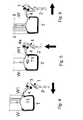
Figure 1 is a perspective view of a disassembling tool according to the present invention; -
Figure 2 is a side view of the device ofFig. 1 in two operative positions; -
Figure 3 is an exploded view of the device ofFig. 1 ; -
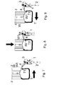
Figures 4 to 6 are side view with parts in cross-section that illustrate respective steps of a disassembling operation of a tyre by means of a disassembling device ofFigs 1 to 3 ; -
Figures 7 to 9 are side view with parts in cross-section that illustrate respective steps of another disassembling operation by means of the disassembling device ofFigs. 1 to 3 ; -
Figures 10, 11 and 12 are perspective slightly from above, front and side views, respectively, of a disassembling machine according to the present invention; -
Figures 13, 14 and 15 are perspective slightly from above, side and top views, respectively, of another embodiment of disassembling machine according to the present invention; -
Figure 16 is a perspective view of another embodiment of a disassembling tool according to the present invention; -
Figure 17 is a cross-section view of the device ofFig. 16 ; and -
Figure 18 is an enlarged view in explosion of the device ofFigs. 16 and 17 . - In the accompanying drawings, similar or the like parts or component are indicated with the same reference numerals.
- With reference first to
Figures 1 to 9 , there is illustrated a disassemblingdevice 1 for disassembling a tyre from a tyred wheel, particularly suitable for relatively large size, e. g. lorry wheels, which comprises a support arm ormember 2, e. g. a straight arm with a longitudinal axis x-x, having ahead end 2a and a connection end, preferably for being removably connected to a support or guide member (seeFigures 10 to 15 ). Thesupport arm 2 preferably bears on its head a fork member, e. g. comprising a pair of parallelopposite plates 3 spaced apart from one another, between which one articulation orproximal end 4a of a bill or lever-shaped disassembling tool 4 is articulated about an axis y-y orthogonal to the longitudinal axis x-x of thearm 2. The other end or work ordistal end 4b of thetool 4 is substantially hook-shaped or the like and is located outside the pair ofplates 3. - The disassembling tool is angularly movable, as further explained below, between a first insertion position between bead T1 of the tyre T and the respective edge W1 of the wheel rim W, and a second engagement and extraction position of the bead T1 of the tyre T.
- If desired, the
tool 4 can be directly articulated to thearm 2. - The
tool 4 can be substantially shaped as a curved bill or lever. In order to make it sturdier, thetool 4 is advantageously U-shaped in cross-section starting from its articulation orproximal end 4a to an area close to its work ordistal end 4b (Fig. 3 ). For pivoting thetool 4 to thesupport arm 2, abush element 11 can, for example, be provided which extends transversally and is rigidly connected, e. g. welded, to thetool 4, e. g. at itsproximal end 4a. With such a configuration, thebush element 11 delimits a throughout axial light that is brought in alignment with two throughopposite holes 12 each formed in arespective plate 3. Anarticulation pin 13 is insertable and lockable in position in any suitable way into theholes 12 and thebush 11. - Advantageously, the axis of the
pin 13 coincides, in use, with the axis y-y substantially orthogonal to the longitudinal axis x-x of thearm 2. - Articulation or pivoting means or returning means can also be provided between the
articulation end 4a of thebill 4 and thesupport arm 2, which are designed to cause thedisassembling tool 4 to return in position. Thetool 4 is movable, in use, between an insertion position (Figures 4 and7 ) and an extraction position (Figures 5, 6 ,8 and 9 ), as further described hereinbelow. The returning means preferably comprise a spring or anotherelastic loading component 6. - The articulation or pivoting means are designed to allow the
disassembling tool 4 to be angularly moved with respect to the support arm ormember 2 between the insertion position and the engagement and extraction position owing to the reaction force of the wheel rim W and/or the tyre T onto thework end 4b during disassembling operations. - The disassembling
device 1 also comprises locking means or holding means for holding thetool 4 in engaging and extraction position, such means being designed to enter into action once thetool 4 has reached an extraction position. Preferably, the holding means comprise an interception element, preferably apin 7 that can be inserted into the arm or theplates 3 and is advantageously elastically loaded, e. g. by aspring 8. Thepin 7 is designed to act as an interception element for thetool 4, as further illustrated hereinbelow. - As it will be understood, the
interception element 7 can be carried either by thesupport member 2 or by the disassemblingtool 4, and is designed to intercept thetool 4 or thesupport member 2, respectively, when thedisassembling tool 4 reaches its engagement and extraction position. - More particularly, the
tool 4 can be angularly moved between an insertion position or starting work position, in which the tool is oriented according to a given angle with respect to the longitudinal axis x-x of thesupport arm 2, e. g. about 120° (Figs. 4 and7 ), whereas the locking orinterception element 7 is in a retracted position (as further explained hereinbelow), in which position it does not hinder the tool articulation or better the angular movement of theproximal end 4a thereof, and an extraction position in which the disassembling tool 4 (in contrast with the action of thespring 8, if provided) is angularly moved to form, e. g. an angle of 90° (Figs. 5 and8 ) with respect to the longitudinal axis x-x. In the extraction position, the locking means spring or are released to reach a position in which they prevent any further articulation movement of thetool 4 with respect to thearm 2. - In its initial work position, the
proximal end 4a of the tool moves flush with and covers the receiving seat of thepin 7, and thus thepin 7 is held in a retracted position in contrast with the spring 8 (Fig. 8 ). When thetool 4 reaches the extraction position, theproximal end 4a sets free or uncovers the receiving zone of the pin orlock 7, whereby thepin 7 urged by thespring 8 enters the space between theplates 3 and reaches a position to act as abutting member for theend 4a (Figs. 5, 6 ,8 and 9 ). - If desired, in the starting work position the
work end 4b of thedisassembling tool 4 has, in use, a trim substantially parallel to the axis of rotation z-z of the wheel to be disassembled or the wheel rim thereof, or is directed towards the axis of rotation z-z. - Preferably, the lock or
pin 7, when thedisassembling tool 4 is in the starting work position, is urged by itsspring 8 to slidingly press against the lateral surface of theproximal end 4a of thetool 4, while it is seated in asleeve 10 overhangingly extending from aplate 3 in the zone between theplates 3. When, instead, the disassemblingtool 4 is brought in the extraction position, thelock 7 under the action of thespring 8 extends out of thesleeve 10 to reach theother plate 3, in which a hole 9 can be provided in alignment with the light of thesleeve 10. The lock can be partly inserted into the hole 9, when the tool is brought in its extraction position. Thesleeve 10, if desired, can also act as a limit switch for the tool in the insertion position (Figs. 4 and7 ). - Since when the
pin 7 is released, it opposes and prevents backward movements of the tool (i. e. from the extraction position to the starting work position). - In order to bring the
tool 4 to the starting work position, it is required to return thepin 7 to its initial position, e. g. by manually or automatically pulling it backwards in any suitable manner. To this end, aknob 7a can be provided which is connected to the pin and can be held from outside theplate 3 bearing thesleeve 10. - The
return spring 8 is instead advantageously connected, at one end thereof, to apawl 14 raising from the side wall of thebush 11 and, at the other end, to apawl 15 secured to one of the plates 3 (that one in which the hole 9 is formed) and externally extending to the zone delimited between the two plates. - Advantageously, the
pawl 14 is designed to contrast angular movements of thedisassembling tool 4 in (clockwise, when seeing the drawings) direction opposite to that from the starting work position to the extraction position, since, should thetool 4 be pushed in that direction, thepawl 14 would bump against the edge of one of theplates 3. - In order to disassemble a tyre T from a wheel rim W of a vehicle wheel, e. g. a lorry wheel, by means of the
disassembling tool 1, after a bead T1 has been bead broken, as it is known, from its respective edge W1 of the wheel rim W, thetool 4 is brought to the starting insertion or work position, i. e. with itswork end 4b abutting against the bead T1 of the tyre T ready to enter between tyre bead T1 and edge W1 of the wheel rim W. Thearm 2 is then moved parallel to the axis of rotation z-z of the wheel (wheel rim W plus tyre T), thereby forcing thework end 4b of thetool 4 to enter between tyre and wheel rim (Figure 4 or7 ). Once thehook end 4b of thetool 4 has moved beyond the bead T1 of the tyre T, a relative movement (typically in a direction parallel to the longitudinal axis x-x of the support arm 2) is caused between wheel anddevice 1, whereby controlling the angular movement of thetool 4 with respect to the wheel between insertion position and extraction position, in which thetool 4 is positively gripping a portion of the tyre bead in order to widen it radially, thereby energizing the holding means (elastically loaded pin 7) to lock in position thetool 4, and thereby preventing any backward movement of thetool 4 with respect to the arm 2 (Figures 5, 6 ,8 and 9 ). - As it will be understood, the relative movement between wheel and disassembling
tool 1 can be carried out by moving thesupport arm 2 in an approaching direction to the axis of rotation z-z of the wheel rim (Figures 4 to 6 ), by moving the wheel or the wheel rim W in an approaching direction to the support arm 2 (Figures 7 to 9 ), or by a combination of such movements. - At this point, the support arm is moved backwards parallel to the axis of the wheel and the wheel or the
tool 4 is set in rotation, thereby bringing the whole bead T1 of the tyre T to move beyond its respective edge W1 of the wheel rim W, thus bringing the disassembling operation to an end. Alternatively, instead of moving thearm 4, the wheel rim W or the tyred wheel can be moved parallel to the axis of rotation z-z. - In a method according to the present invention, the tool is advantageously always in contact with the wheel rim W and/or the tyre T, as they (the wheel rim W and/or the tyre T) cause, owing to respective reaction forces, the tool to angularly move during the disassembling steps.
- The
device 1 does not comprise any actuator designed to control thetool 4, but only articulation means and locking means. Thetool 4 is thus moved between starting work position and extraction position due to the action or reaction force of the wheel rim W and/or the tyre T. - A disassembling method is described with reference to the device according to the present invention, however, it will be understood that in general a disassembling method of a tyre bead from its respective edge of a wheel rim according to the present invention, comprises the following steps in sequence:
- bringing a bill-shaped
disassembling tool 4 in an insertion position, in which itswork end 4b is abutting against the tyre bead T1 of the tyred wheel to be disassembled and advantageously oriented substantially parallel to the axis of rotation z-z of the tyred wheel or of the respective wheel rim W, or directed towards the axis of rotation z-z, - causing a relative movement between the disassembling
tool 4 and the wheel rim W in a direction parallel to the axis of rotation z-z, thereby forcing thework end 4b of thetool 4 to enter between tyre T and wheel rim W and to go beyond the tyre bead T1, - causing a relative movement along a direction orthogonal to the axis of rotation z-z between wheel rim W and
tool 4, whereby causing an angular movement of thetool 4 between the first insertion position and a second extraction position, in which thework end 4b is arranged in the sense of moving away from the axis of rotation z-z and force engaged with the tyre bead T1 which is thus radially widened, thereby energizing holding means to lock in position thetool 4, - moving backwards the
disassembling tool 4 and/or the wheel rim W parallely to the axis of rotation z-z, and - setting in rotation the wheel or the tool thereby bringing the whole tyre bead T1 beyond the edge W1 of the wheel rim W.
- Preferably, such method is carried out by means of the device according to the present invention, as well as with a machine according to the present invention.
- With reference to the embodiment illustrated in
Figures 10 to 12 , there is illustrated a tyre assembling-disassemblingmachine 15 comprising abase 16, support means and rotational drive means 17 for a tyred wheel mounted for rotation about a horizontal, in use, axis z-z on said support means, as well as a substantiallyhorizontal guide member 18, on which the support member orarm 2 of adevice 1 according to the present invention is slidably mounted. - The embodiment shown in
Figures 13 to 15 , an assembling-disassemblingmachine 19 similar to that described above is shown where the support means and the rotational drive means 17 are designed to cause a tyred wheel to rotate about a vertical axis z-z, whereas theguide member 18 allows movements in a substantially vertical direction. - With reference to the embodiment shown in
Figures 16 to 18 , a disassembling device similar to that illustrated inFigs. 1 to 3 is shown which is also provided with abead breaking roller 23 that can be connected, preferably pivoted, to thearm 2. More particularly, theroller 23 can be provided with acentral pin 24 inserted and locked in position for rotation in a sleeve 25 secured in a respective bore formed in aplate 26 bridge connecting theplates 3. - The axis of rotation w-w of the
roller 23 is substantially orthogonal to the articulation axis y-y of thetool 4, and inclined with respect to the longitudinal axis x-x of thesupport arm 2. - With such a device, first one tyre bead is bead broken by means of the
roller 23, as it is common practice in the art, from its respective edge of the wheel rim, and then thearm 2 is set in rotation and thetool 4 is controlled as indicated above. - As it will be understood, unlike the devices and the machines described in the European patent applications
EP-1 177 920 andEP-1 398 184 the above described device according to the present invention is not equipped with actuators for controlling articulations movements of thetool 4, and has in any case a much simpler and cheaper to produce. - With respect to the device disclosed in the European patent application
EP-1 714 807 , the above described device has, among the other things, locking means arranged to block thetool 4 in position once it has been brought in extraction position. This is particularly advantageous as the disassemblingdevice 1 is suitable for firmly holding the position of the tire bead engaged and grasped by it throughout the whole extraction or dragging operation beyond the edge of its respective wheel rim. - As it will be noted, a
disassembling device 1 is preferably pivoted to thearm 2, and thus it can be only angularly moved with respect to thearm 2, whereas in the case of the European patent applicationEP-1 714 807 the tool can effect roto-translational movements with respect to the support arm. The combination of rotation and translation with such prior art device is required to ensure a suitable relative movement between tool and components of the wheel during a disassembling operation. - In a device according to the present invention, instead, part of the translation movement required between
tool 4 and components of the wheel can be obtained owing to the provision of locking means that, after the tool has been angularly displaced, block thetool 4 in position, and following the movement of thesupport arm 2 thetool 4 effects translation movements with respect to the wheel rim W. - The disassembling device, the disassembling machine, and the disassembling method described above are susceptible to numerous modifications and variations within the scope of protection of the following claims.
Claims (14)
- A device for dismounting a tyred wheel having a wheel rim (W) and a tyre (T) mounted on the wheel rim (W), comprising:- a support member (2),- a bill or lever-shaped dismounting tool (4) having one end (4a) thereof articulated to said support member (2), and the other work end (4b) thereof substantially hook-shaped, whereby said dismounting tool (4) can be angularly displaced between a first insertion position between the tyre bead (T1) of the tyre (T) and edge (W1) of the wheel rim (W) and a second engagement and extraction position of the tyre bead (T1),characterized in that it comprises holding means for holding said tool (4) in an engagement and extraction position having an interception element (7) carried either by said support member (2) or by said disassembling tool (4) and arranged to intercept said tool (4) or said support member (2), respectively, when said disassembling tool (4) reaches said engagement and extraction position, and in that said holding means comprise an elastically loaded pin (7).
- A device as claimed in claim 1, characterized in that it comprises returning means or articulation or pivoting means (6) between said articulation end (4a) and said support member (2), designed to allow angular displacements of said disassembling tool (4) with respect to said support member (2) between said insertion position and said engagement and extraction position due to the reaction force of a wheel rim (W) and/or the tyre (T) onto the work end (4b).
- A device as claimed in claim 1 or 2, characterized in that, when said tool is in the first insertion position, said holding means (7) are in a retracted position in which they do not hinder the tool articulation, whereas, when the tool is moved into the second extraction position said holding means spring or are triggered into a position in which they block any further articulation movement of said tool (4) with respect to said support member (2).
- A device as claimed in any previous claim, characterized in that in said support member (2) a hole or sleeve (10) is provided in which said elastically loaded pin (7) is slidably mounted.
- A device as claimed in any previous claim, characterized in that said returning means comprises an elastically loading component (6) designed to cause the disassembling tool (4) to return to its insertion position.
- A device as claimed in any previous claim, characterized in that it comprises a pair of plates (3) mounted at the end of said support member, said tool being pivoted or articulated to said plates (3).
- A device as claimed in any previous claim, characterized in that it comprises a bush element (11) connected to the proximal end (4a) of said tool (4) and delimiting an axial light alignable with respective holes (12) formed in said support member (2), and in which an articulation pin (13) can be inserted and locked.
- A device as claimed in any previous claim, characterized in that it comprises a bead breaking roller (23) connected or pivoted to said support member (2).
- A device as claimed in claim 8, characterized in that said roller (23) has a central pin (24) inserted and locked in position in a sleeve (25) secured in a respective hole formed in a plate (26) connected to said support member (2).
- An assembling-disassembling machine comprising a base (16), support means and rotational drive means (17) for a tyred wheel mounted for rotation about a horizontal or vertical axis (z-z), a guide member (18) on which said support member (2) of a device (1) according to any previous claim is slidably mounted.
- A method of disassembling a tyre bead from its respective wheel rim edge, comprising the following steps in sequence:- arranging a disassembling bill tool (4) in an insertion position in which a work end (4b) thereof is abutting against said tyre bead (T1) of a tyred wheel to be disassembled,- causing a relative movement between said disassembling tool (4) and said wheel rim (W) in a direction parallel to the axis of rotation (z-z) of said tyred wheel or of said wheel rim (W), thereby forcing the work end (4b) of said tool (4) to enter between the tyre (T) and the wheel rim (W) and to go beyond the tyre bead (T1),- causing a relative movement along an orthogonal direction to said axis of rotation (z-z) between wheel rim (W) and tool (4), thereby causing an angular movement of said tool (4) between said first insertion position and a second extraction position, where said work end (4b) is facing in the direction moving away from the axis of rotation (z-z) and is forced grasping with said tyre bead (T1) that is thus radially widened, thereby energizing holding means to lock said tool (4) in position,- moving backwards said disassembling tool (4) and/or said wheel rim (W) parallel to said axis of rotation (z-z), and- causing said wheel or said tool to rotate, thereby bringing the whole tyre bead (T1) beyond the edge (W1) of the wheel rim (W).
- A method as claimed in claim 11, characterized in that during said relative movement the tool is moved from said insertion position to said extraction position owing to the reaction force applied onto the tool by the wheel rim (W).
- A method as claimed in claim 11 or 12, characterized in that it is carried out through a disassembling device according to any previous claim 1 to 9.
- A method as claimed in claim 13, characterized in that in said step, in which a relative movement along a direction orthogonal to said axis of rotation (z-z) is caused, wheel rim (W) and tool (4) are relatively moved along a direction parallel to the longitudinal axis (x-x) of said support member (2).
Applications Claiming Priority (1)
| Application Number | Priority Date | Filing Date | Title |
|---|---|---|---|
| IT000159A ITVR20120159A1 (en) | 2012-08-01 | 2012-08-01 | DISMANTLING DEVICE OF A TIRE FROM A RIM AND METHOD OF DISASSEMBLY OF A WHEELED WHEEL |
Publications (2)
| Publication Number | Publication Date |
|---|---|
| EP2692553A1 true EP2692553A1 (en) | 2014-02-05 |
| EP2692553B1 EP2692553B1 (en) | 2015-03-04 |
Family
ID=46845958
Family Applications (1)
| Application Number | Title | Priority Date | Filing Date |
|---|---|---|---|
| EP13176457.3A Active EP2692553B1 (en) | 2012-08-01 | 2013-07-15 | A device for disassembling a tyre from a wheel rim and a method of disassembling a tyred wheel. |
Country Status (3)
| Country | Link |
|---|---|
| US (1) | US10189322B2 (en) |
| EP (1) | EP2692553B1 (en) |
| IT (1) | ITVR20120159A1 (en) |
Cited By (4)
| Publication number | Priority date | Publication date | Assignee | Title |
|---|---|---|---|---|
| EP2949488A1 (en) | 2014-05-30 | 2015-12-02 | Snap-on Equipment Srl a unico socio | Mounting/demounting tool unit with preloaded tool |
| EP2949486A1 (en) | 2014-05-30 | 2015-12-02 | Snap-on Equipment Srl a unico socio | Method for mounting and demounting a tyre to and from a wheel rim |
| DE202014008932U1 (en) | 2014-11-11 | 2016-03-02 | Snap-On Equipment Srl A Unico Socio | Tire mounting and dismounting tool |
| CN106926650A (en) * | 2017-04-25 | 2017-07-07 | 大力汽保(营口)装备制造有限公司 | A kind of vertical tyre disassembling devices |
Families Citing this family (3)
| Publication number | Priority date | Publication date | Assignee | Title |
|---|---|---|---|---|
| CN107379902B (en) * | 2016-05-16 | 2023-07-11 | 苏州工业园区泰格电子科技有限公司 | Tire mounting device |
| CN107379903A (en) * | 2016-05-16 | 2017-11-24 | 苏州工业园区泰格电子科技有限公司 | Tire automatic installation apparatus |
| IT201600111370A1 (en) * | 2016-11-04 | 2018-05-04 | Nexion Spa | APPARATUS FOR MOUNTING AND DISASSEMBLING A TIRE |
Citations (6)
| Publication number | Priority date | Publication date | Assignee | Title |
|---|---|---|---|---|
| EP1177920A2 (en) | 2000-08-03 | 2002-02-06 | CORGHI S.p.A. | Automatic tyre removal and mounting device, and tyre removal machines equipped therewith |
| EP1398184A1 (en) | 2002-09-13 | 2004-03-17 | CORGHI S.p.A. | Simplified automatic tyre demounting device, and tyre removal machines equipped therewith |
| EP1714807A1 (en) | 2005-03-23 | 2006-10-25 | BUTLER ENGINEERING & MARKETING SPA | Tool for automatically assembling or disassembling a tyre to/from a wheel rim |
| WO2009130135A1 (en) | 2008-04-21 | 2009-10-29 | Corghi S.P.A. | A tyre-changing machine and a relative bead-breaking method |
| WO2009138322A1 (en) | 2008-05-15 | 2009-11-19 | Corghi S.P.A. | A tyre-removing method and a tyre-changing machine |
| EP2463125A1 (en) | 2010-12-09 | 2012-06-13 | Butler Engineering & Marketing S.p.A. | A device for demounting a tire from a rim as well as a tire demounting machine equipped with such device. |
Family Cites Families (1)
| Publication number | Priority date | Publication date | Assignee | Title |
|---|---|---|---|---|
| ITRE20040049A1 (en) * | 2004-05-06 | 2004-08-06 | Corghi Spa | AUTOMATIC DEVICE FOR DISASSEMBLY AND ASSEMBLY OF TIRES |
-
2012
- 2012-08-01 IT IT000159A patent/ITVR20120159A1/en unknown
-
2013
- 2013-07-15 EP EP13176457.3A patent/EP2692553B1/en active Active
- 2013-07-30 US US13/954,510 patent/US10189322B2/en active Active
Patent Citations (6)
| Publication number | Priority date | Publication date | Assignee | Title |
|---|---|---|---|---|
| EP1177920A2 (en) | 2000-08-03 | 2002-02-06 | CORGHI S.p.A. | Automatic tyre removal and mounting device, and tyre removal machines equipped therewith |
| EP1398184A1 (en) | 2002-09-13 | 2004-03-17 | CORGHI S.p.A. | Simplified automatic tyre demounting device, and tyre removal machines equipped therewith |
| EP1714807A1 (en) | 2005-03-23 | 2006-10-25 | BUTLER ENGINEERING & MARKETING SPA | Tool for automatically assembling or disassembling a tyre to/from a wheel rim |
| WO2009130135A1 (en) | 2008-04-21 | 2009-10-29 | Corghi S.P.A. | A tyre-changing machine and a relative bead-breaking method |
| WO2009138322A1 (en) | 2008-05-15 | 2009-11-19 | Corghi S.P.A. | A tyre-removing method and a tyre-changing machine |
| EP2463125A1 (en) | 2010-12-09 | 2012-06-13 | Butler Engineering & Marketing S.p.A. | A device for demounting a tire from a rim as well as a tire demounting machine equipped with such device. |
Cited By (7)
| Publication number | Priority date | Publication date | Assignee | Title |
|---|---|---|---|---|
| EP2949488A1 (en) | 2014-05-30 | 2015-12-02 | Snap-on Equipment Srl a unico socio | Mounting/demounting tool unit with preloaded tool |
| EP2949486A1 (en) | 2014-05-30 | 2015-12-02 | Snap-on Equipment Srl a unico socio | Method for mounting and demounting a tyre to and from a wheel rim |
| EP3501862A1 (en) | 2014-05-30 | 2019-06-26 | Snap-on Equipment Srl a unico socio | Method for mounting and demounting a tyre to and from a wheel rim |
| US11214103B2 (en) | 2014-05-30 | 2022-01-04 | Snap-On Equipment Srl A Unico Socio | Method for mounting and demounting a tyre to and from a wheel rim |
| DE202014008932U1 (en) | 2014-11-11 | 2016-03-02 | Snap-On Equipment Srl A Unico Socio | Tire mounting and dismounting tool |
| CN106926650A (en) * | 2017-04-25 | 2017-07-07 | 大力汽保(营口)装备制造有限公司 | A kind of vertical tyre disassembling devices |
| CN106926650B (en) * | 2017-04-25 | 2019-04-05 | 营口大力汽保设备科技有限公司 | A kind of vertical tyre disassembling devices |
Also Published As
| Publication number | Publication date |
|---|---|
| EP2692553B1 (en) | 2015-03-04 |
| US20140034248A1 (en) | 2014-02-06 |
| ITVR20120159A1 (en) | 2014-02-02 |
| US10189322B2 (en) | 2019-01-29 |
Similar Documents
| Publication | Publication Date | Title |
|---|---|---|
| EP2692553B1 (en) | A device for disassembling a tyre from a wheel rim and a method of disassembling a tyred wheel. | |
| EP2463125B1 (en) | A device for demounting a tire from a rim as well as a tire demounting machine equipped with such device. | |
| EP2468541B1 (en) | Device for demounting the second bead of a tire from a rim and respective demounting method | |
| EP1714807B2 (en) | Tool for automatically assembling or disassembling a tyre to/from a wheel rim | |
| EP2524821B1 (en) | Device for the automatic demounting of a tire from a rim and machine equipped with such device | |
| EP2962876B1 (en) | Machine and method for fitting and removing a tyre | |
| EP2965927B1 (en) | Machine and method for fitting and removing a tyre | |
| EP2629992B1 (en) | A tyre demounting machine | |
| EP2987661B1 (en) | Device for assembling-disassembling a tyred wheel, as well as machine comprising such a device | |
| EP2338705B1 (en) | Bead breaking unit for tyre changing machines | |
| JP2006290340A (en) | Attaching/detaching device with laterally rotatable fitting/removing tool | |
| US9216621B2 (en) | Apparatus for angular positioning of an operating arm of a tire changing machine | |
| EP2527166B1 (en) | bead breaking unit for tyre changing machines | |
| JP5404162B2 (en) | Bead breaker group for tire installation / removal machines | |
| JP2012121567A5 (en) | ||
| EP2995478B1 (en) | Machine for removing and fitting wheel tyres for vehicles | |
| WO2009138322A1 (en) | A tyre-removing method and a tyre-changing machine | |
| EP3575112B1 (en) | Tyre changing machine | |
| EP2949488B1 (en) | Mounting/demounting tool unit with preloaded tool | |
| CN111016557A (en) | Machine for mounting and/or demounting vehicle wheels, in particular truck wheels | |
| EP2756969B1 (en) | Machine for removing/ fitting a tyre from/ on the rim of a vehicle vehicles | |
| US20230123205A1 (en) | Machine for mounting and demounting a tyre relative to a corresponding rim and wheel servicing method |
Legal Events
| Date | Code | Title | Description |
|---|---|---|---|
| AK | Designated contracting states |
Kind code of ref document: A1 Designated state(s): AL AT BE BG CH CY CZ DE DK EE ES FI FR GB GR HR HU IE IS IT LI LT LU LV MC MK MT NL NO PL PT RO RS SE SI SK SM TR |
|
| AX | Request for extension of the european patent |
Extension state: BA ME |
|
| PUAI | Public reference made under article 153(3) epc to a published international application that has entered the european phase |
Free format text: ORIGINAL CODE: 0009012 |
|
| 17P | Request for examination filed |
Effective date: 20140710 |
|
| RBV | Designated contracting states (corrected) |
Designated state(s): AL AT BE BG CH CY CZ DE DK EE ES FI FR GB GR HR HU IE IS IT LI LT LU LV MC MK MT NL NO PL PT RO RS SE SI SK SM TR |
|
| GRAP | Despatch of communication of intention to grant a patent |
Free format text: ORIGINAL CODE: EPIDOSNIGR1 |
|
| INTG | Intention to grant announced |
Effective date: 20140916 |
|
| GRAS | Grant fee paid |
Free format text: ORIGINAL CODE: EPIDOSNIGR3 |
|
| GRAA | (expected) grant |
Free format text: ORIGINAL CODE: 0009210 |
|
| AK | Designated contracting states |
Kind code of ref document: B1 Designated state(s): AL AT BE BG CH CY CZ DE DK EE ES FI FR GB GR HR HU IE IS IT LI LT LU LV MC MK MT NL NO PL PT RO RS SE SI SK SM TR |
|
| REG | Reference to a national code |
Ref country code: GB Ref legal event code: FG4D |
|
| REG | Reference to a national code |
Ref country code: CH Ref legal event code: EP |
|
| REG | Reference to a national code |
Ref country code: IE Ref legal event code: FG4D |
|
| REG | Reference to a national code |
Ref country code: AT Ref legal event code: REF Ref document number: 713519 Country of ref document: AT Kind code of ref document: T Effective date: 20150415 |
|
| REG | Reference to a national code |
Ref country code: DE Ref legal event code: R096 Ref document number: 602013001081 Country of ref document: DE Effective date: 20150416 |
|
| REG | Reference to a national code |
Ref country code: AT Ref legal event code: MK05 Ref document number: 713519 Country of ref document: AT Kind code of ref document: T Effective date: 20150304 Ref country code: NL Ref legal event code: VDEP Effective date: 20150304 |
|
| PG25 | Lapsed in a contracting state [announced via postgrant information from national office to epo] |
Ref country code: FI Free format text: LAPSE BECAUSE OF FAILURE TO SUBMIT A TRANSLATION OF THE DESCRIPTION OR TO PAY THE FEE WITHIN THE PRESCRIBED TIME-LIMIT Effective date: 20150304 Ref country code: LT Free format text: LAPSE BECAUSE OF FAILURE TO SUBMIT A TRANSLATION OF THE DESCRIPTION OR TO PAY THE FEE WITHIN THE PRESCRIBED TIME-LIMIT Effective date: 20150304 Ref country code: ES Free format text: LAPSE BECAUSE OF FAILURE TO SUBMIT A TRANSLATION OF THE DESCRIPTION OR TO PAY THE FEE WITHIN THE PRESCRIBED TIME-LIMIT Effective date: 20150304 Ref country code: SE Free format text: LAPSE BECAUSE OF FAILURE TO SUBMIT A TRANSLATION OF THE DESCRIPTION OR TO PAY THE FEE WITHIN THE PRESCRIBED TIME-LIMIT Effective date: 20150304 Ref country code: NO Free format text: LAPSE BECAUSE OF FAILURE TO SUBMIT A TRANSLATION OF THE DESCRIPTION OR TO PAY THE FEE WITHIN THE PRESCRIBED TIME-LIMIT Effective date: 20150604 Ref country code: HR Free format text: LAPSE BECAUSE OF FAILURE TO SUBMIT A TRANSLATION OF THE DESCRIPTION OR TO PAY THE FEE WITHIN THE PRESCRIBED TIME-LIMIT Effective date: 20150304 |
|
| REG | Reference to a national code |
Ref country code: LT Ref legal event code: MG4D |
|
| PG25 | Lapsed in a contracting state [announced via postgrant information from national office to epo] |
Ref country code: LV Free format text: LAPSE BECAUSE OF FAILURE TO SUBMIT A TRANSLATION OF THE DESCRIPTION OR TO PAY THE FEE WITHIN THE PRESCRIBED TIME-LIMIT Effective date: 20150304 Ref country code: GR Free format text: LAPSE BECAUSE OF FAILURE TO SUBMIT A TRANSLATION OF THE DESCRIPTION OR TO PAY THE FEE WITHIN THE PRESCRIBED TIME-LIMIT Effective date: 20150605 Ref country code: AT Free format text: LAPSE BECAUSE OF FAILURE TO SUBMIT A TRANSLATION OF THE DESCRIPTION OR TO PAY THE FEE WITHIN THE PRESCRIBED TIME-LIMIT Effective date: 20150304 Ref country code: RS Free format text: LAPSE BECAUSE OF FAILURE TO SUBMIT A TRANSLATION OF THE DESCRIPTION OR TO PAY THE FEE WITHIN THE PRESCRIBED TIME-LIMIT Effective date: 20150304 |
|
| PG25 | Lapsed in a contracting state [announced via postgrant information from national office to epo] |
Ref country code: NL Free format text: LAPSE BECAUSE OF FAILURE TO SUBMIT A TRANSLATION OF THE DESCRIPTION OR TO PAY THE FEE WITHIN THE PRESCRIBED TIME-LIMIT Effective date: 20150304 |
|
| PG25 | Lapsed in a contracting state [announced via postgrant information from national office to epo] |
Ref country code: PT Free format text: LAPSE BECAUSE OF FAILURE TO SUBMIT A TRANSLATION OF THE DESCRIPTION OR TO PAY THE FEE WITHIN THE PRESCRIBED TIME-LIMIT Effective date: 20150706 Ref country code: EE Free format text: LAPSE BECAUSE OF FAILURE TO SUBMIT A TRANSLATION OF THE DESCRIPTION OR TO PAY THE FEE WITHIN THE PRESCRIBED TIME-LIMIT Effective date: 20150304 Ref country code: SK Free format text: LAPSE BECAUSE OF FAILURE TO SUBMIT A TRANSLATION OF THE DESCRIPTION OR TO PAY THE FEE WITHIN THE PRESCRIBED TIME-LIMIT Effective date: 20150304 Ref country code: CZ Free format text: LAPSE BECAUSE OF FAILURE TO SUBMIT A TRANSLATION OF THE DESCRIPTION OR TO PAY THE FEE WITHIN THE PRESCRIBED TIME-LIMIT Effective date: 20150304 Ref country code: RO Free format text: LAPSE BECAUSE OF FAILURE TO SUBMIT A TRANSLATION OF THE DESCRIPTION OR TO PAY THE FEE WITHIN THE PRESCRIBED TIME-LIMIT Effective date: 20150304 |
|
| PG25 | Lapsed in a contracting state [announced via postgrant information from national office to epo] |
Ref country code: IS Free format text: LAPSE BECAUSE OF FAILURE TO SUBMIT A TRANSLATION OF THE DESCRIPTION OR TO PAY THE FEE WITHIN THE PRESCRIBED TIME-LIMIT Effective date: 20150704 Ref country code: PL Free format text: LAPSE BECAUSE OF FAILURE TO SUBMIT A TRANSLATION OF THE DESCRIPTION OR TO PAY THE FEE WITHIN THE PRESCRIBED TIME-LIMIT Effective date: 20150304 |
|
| REG | Reference to a national code |
Ref country code: DE Ref legal event code: R097 Ref document number: 602013001081 Country of ref document: DE |
|
| PLBE | No opposition filed within time limit |
Free format text: ORIGINAL CODE: 0009261 |
|
| STAA | Information on the status of an ep patent application or granted ep patent |
Free format text: STATUS: NO OPPOSITION FILED WITHIN TIME LIMIT |
|
| PG25 | Lapsed in a contracting state [announced via postgrant information from national office to epo] |
Ref country code: DK Free format text: LAPSE BECAUSE OF FAILURE TO SUBMIT A TRANSLATION OF THE DESCRIPTION OR TO PAY THE FEE WITHIN THE PRESCRIBED TIME-LIMIT Effective date: 20150304 |
|
| 26N | No opposition filed |
Effective date: 20151207 |
|
| PG25 | Lapsed in a contracting state [announced via postgrant information from national office to epo] |
Ref country code: SI Free format text: LAPSE BECAUSE OF FAILURE TO SUBMIT A TRANSLATION OF THE DESCRIPTION OR TO PAY THE FEE WITHIN THE PRESCRIBED TIME-LIMIT Effective date: 20150304 Ref country code: MC Free format text: LAPSE BECAUSE OF FAILURE TO SUBMIT A TRANSLATION OF THE DESCRIPTION OR TO PAY THE FEE WITHIN THE PRESCRIBED TIME-LIMIT Effective date: 20150304 |
|
| PG25 | Lapsed in a contracting state [announced via postgrant information from national office to epo] |
Ref country code: LU Free format text: LAPSE BECAUSE OF FAILURE TO SUBMIT A TRANSLATION OF THE DESCRIPTION OR TO PAY THE FEE WITHIN THE PRESCRIBED TIME-LIMIT Effective date: 20150715 |
|
| REG | Reference to a national code |
Ref country code: IE Ref legal event code: MM4A |
|
| REG | Reference to a national code |
Ref country code: FR Ref legal event code: ST Effective date: 20160331 |
|
| PG25 | Lapsed in a contracting state [announced via postgrant information from national office to epo] |
Ref country code: FR Free format text: LAPSE BECAUSE OF NON-PAYMENT OF DUE FEES Effective date: 20150731 |
|
| PG25 | Lapsed in a contracting state [announced via postgrant information from national office to epo] |
Ref country code: IE Free format text: LAPSE BECAUSE OF NON-PAYMENT OF DUE FEES Effective date: 20150715 |
|
| PG25 | Lapsed in a contracting state [announced via postgrant information from national office to epo] |
Ref country code: BE Free format text: LAPSE BECAUSE OF FAILURE TO SUBMIT A TRANSLATION OF THE DESCRIPTION OR TO PAY THE FEE WITHIN THE PRESCRIBED TIME-LIMIT Effective date: 20150304 |
|
| REG | Reference to a national code |
Ref country code: CH Ref legal event code: PL |
|
| PG25 | Lapsed in a contracting state [announced via postgrant information from national office to epo] |
Ref country code: MT Free format text: LAPSE BECAUSE OF FAILURE TO SUBMIT A TRANSLATION OF THE DESCRIPTION OR TO PAY THE FEE WITHIN THE PRESCRIBED TIME-LIMIT Effective date: 20150304 |
|
| PG25 | Lapsed in a contracting state [announced via postgrant information from national office to epo] |
Ref country code: CH Free format text: LAPSE BECAUSE OF NON-PAYMENT OF DUE FEES Effective date: 20160731 Ref country code: LI Free format text: LAPSE BECAUSE OF NON-PAYMENT OF DUE FEES Effective date: 20160731 |
|
| PG25 | Lapsed in a contracting state [announced via postgrant information from national office to epo] |
Ref country code: HU Free format text: LAPSE BECAUSE OF FAILURE TO SUBMIT A TRANSLATION OF THE DESCRIPTION OR TO PAY THE FEE WITHIN THE PRESCRIBED TIME-LIMIT; INVALID AB INITIO Effective date: 20130715 Ref country code: BG Free format text: LAPSE BECAUSE OF FAILURE TO SUBMIT A TRANSLATION OF THE DESCRIPTION OR TO PAY THE FEE WITHIN THE PRESCRIBED TIME-LIMIT Effective date: 20150304 |
|
| PG25 | Lapsed in a contracting state [announced via postgrant information from national office to epo] |
Ref country code: CY Free format text: LAPSE BECAUSE OF FAILURE TO SUBMIT A TRANSLATION OF THE DESCRIPTION OR TO PAY THE FEE WITHIN THE PRESCRIBED TIME-LIMIT Effective date: 20150304 |
|
| GBPC | Gb: european patent ceased through non-payment of renewal fee |
Effective date: 20170715 |
|
| PG25 | Lapsed in a contracting state [announced via postgrant information from national office to epo] |
Ref country code: GB Free format text: LAPSE BECAUSE OF NON-PAYMENT OF DUE FEES Effective date: 20170715 |
|
| PG25 | Lapsed in a contracting state [announced via postgrant information from national office to epo] |
Ref country code: SM Free format text: LAPSE BECAUSE OF FAILURE TO SUBMIT A TRANSLATION OF THE DESCRIPTION OR TO PAY THE FEE WITHIN THE PRESCRIBED TIME-LIMIT Effective date: 20150304 |
|
| PG25 | Lapsed in a contracting state [announced via postgrant information from national office to epo] |
Ref country code: MK Free format text: LAPSE BECAUSE OF FAILURE TO SUBMIT A TRANSLATION OF THE DESCRIPTION OR TO PAY THE FEE WITHIN THE PRESCRIBED TIME-LIMIT Effective date: 20150304 Ref country code: TR Free format text: LAPSE BECAUSE OF FAILURE TO SUBMIT A TRANSLATION OF THE DESCRIPTION OR TO PAY THE FEE WITHIN THE PRESCRIBED TIME-LIMIT Effective date: 20150304 |
|
| PG25 | Lapsed in a contracting state [announced via postgrant information from national office to epo] |
Ref country code: AL Free format text: LAPSE BECAUSE OF FAILURE TO SUBMIT A TRANSLATION OF THE DESCRIPTION OR TO PAY THE FEE WITHIN THE PRESCRIBED TIME-LIMIT Effective date: 20150304 |
|
| P01 | Opt-out of the competence of the unified patent court (upc) registered |
Effective date: 20230515 |
|
| PGFP | Annual fee paid to national office [announced via postgrant information from national office to epo] |
Ref country code: IT Payment date: 20230721 Year of fee payment: 11 |
|
| PGFP | Annual fee paid to national office [announced via postgrant information from national office to epo] |
Ref country code: DE Payment date: 20230726 Year of fee payment: 11 |