JP5404162B2 - Bead breaker group for tire installation / removal machines - Google Patents
Bead breaker group for tire installation / removal machines Download PDFInfo
- Publication number
- JP5404162B2 JP5404162B2 JP2009108450A JP2009108450A JP5404162B2 JP 5404162 B2 JP5404162 B2 JP 5404162B2 JP 2009108450 A JP2009108450 A JP 2009108450A JP 2009108450 A JP2009108450 A JP 2009108450A JP 5404162 B2 JP5404162 B2 JP 5404162B2
- Authority
- JP
- Japan
- Prior art keywords
- tire
- bead
- tool
- bead breaker
- rim
- Prior art date
- Legal status (The legal status is an assumption and is not a legal conclusion. Google has not performed a legal analysis and makes no representation as to the accuracy of the status listed.)
- Expired - Fee Related
Links
Images


Classifications
-
- B—PERFORMING OPERATIONS; TRANSPORTING
- B60—VEHICLES IN GENERAL
- B60C—VEHICLE TYRES; TYRE INFLATION; TYRE CHANGING; CONNECTING VALVES TO INFLATABLE ELASTIC BODIES IN GENERAL; DEVICES OR ARRANGEMENTS RELATED TO TYRES
- B60C25/00—Apparatus or tools adapted for mounting, removing or inspecting tyres
- B60C25/01—Apparatus or tools adapted for mounting, removing or inspecting tyres for removing tyres from or mounting tyres on wheels
- B60C25/05—Machines
- B60C25/125—Machines for only breaking the beads
- B60C25/13—Machines for only breaking the beads acting axially on a part of the bead or side wall only at localised regions of the bead or side wall
-
- B—PERFORMING OPERATIONS; TRANSPORTING
- B60—VEHICLES IN GENERAL
- B60C—VEHICLE TYRES; TYRE INFLATION; TYRE CHANGING; CONNECTING VALVES TO INFLATABLE ELASTIC BODIES IN GENERAL; DEVICES OR ARRANGEMENTS RELATED TO TYRES
- B60C25/00—Apparatus or tools adapted for mounting, removing or inspecting tyres
- B60C25/01—Apparatus or tools adapted for mounting, removing or inspecting tyres for removing tyres from or mounting tyres on wheels
- B60C25/05—Machines
- B60C25/132—Machines for removing and mounting tyres
- B60C25/135—Machines for removing and mounting tyres having a tyre support or a tool, movable along wheel axis
- B60C25/138—Machines for removing and mounting tyres having a tyre support or a tool, movable along wheel axis with rotary motion of tool or tyre support
-
- Y—GENERAL TAGGING OF NEW TECHNOLOGICAL DEVELOPMENTS; GENERAL TAGGING OF CROSS-SECTIONAL TECHNOLOGIES SPANNING OVER SEVERAL SECTIONS OF THE IPC; TECHNICAL SUBJECTS COVERED BY FORMER USPC CROSS-REFERENCE ART COLLECTIONS [XRACs] AND DIGESTS
- Y10—TECHNICAL SUBJECTS COVERED BY FORMER USPC
- Y10T—TECHNICAL SUBJECTS COVERED BY FORMER US CLASSIFICATION
- Y10T29/00—Metal working
- Y10T29/49—Method of mechanical manufacture
- Y10T29/49481—Wheel making
- Y10T29/49492—Land wheel
- Y10T29/49494—Assembling tire to wheel body
Landscapes
- Engineering & Computer Science (AREA)
- Mechanical Engineering (AREA)
- Tires In General (AREA)
- Automatic Tape Cassette Changers (AREA)
- Automatic Tool Replacement In Machine Tools (AREA)
Description
本発明は、ビードブレーカーグループ、及びこのグループを備えるタイヤ取付け/取外し機、並びにリムに取付けられたタイヤのビード落としを行う新規な方法に関する。 The present invention relates to a group of bead breakers, a tire mounting / dismounting machine comprising this group, and a novel method for bead dropping of a tire mounted on a rim.
公知のように、タイヤをリムから外すために、最初に、タイヤのビード落としを行う、すなわち、リムの各縁部からそのビードを分離して、適宜なタイヤ取付け/取外し工具によってタイヤの少なくとも一つのビードにそれに対面するリムの縁部を越えさせる必要がある。ビード落とし作業は、固定型であり得るか又は遊転ローラとして構成され得る、いわゆる、ビードブレーカー工具によってなされる。 As is known, in order to remove the tire from the rim, first the tire bead is dropped, i.e. the bead is separated from each edge of the rim and at least one of the tires is removed by means of a suitable tire mounting / removal tool. One bead needs to cross the edge of the rim facing it. The bead dropping operation is done with a so-called bead breaker tool, which can be fixed or configured as an idler roller.
ごく最近考えられたタイヤ取付け/取外し機は、サポート基部上で回転するように取付け配置されたホイール保持テーブルと、基部から立ち上がっていると共に一つ又は二つの伸縮自在なアームが突出するように伸びているコラムとを備え、ビードブレーカーローラがそのアームの自由端に支持されている。各ビードブレーカーローラは、通常、切頭台形で、やや平坦であり、傾斜回転軸を、例えば45°にして軸方向に且つ回転自在に支持されており、その伸縮自在な各アームの長手軸を通る平面内に含まれ、その結果、ローラは、(コラムに対する)それ自体の近(端)部に対してコラムからさらに離れている遠(端)部(使用時には、ビード落としがなされるべきタイヤに近接する)を有する。 A very recently conceived tire mounting / dismounting machine is a wheel holding table mounted and arranged to rotate on a support base, and stands up from the base and extends so that one or two telescoping arms protrude. And a bead breaker roller supported on the free end of the arm. Each bead breaker roller is usually truncated trapezoidal and slightly flat, and is rotatably supported in an axial direction with an inclined rotation axis of, for example, 45 °. The longitudinal axis of each telescopic arm is extendable. The tire is to be bead dropped in use, as a result of which the roller is farther away from the column (in use) than its own near (end) part (relative to the column) Close to).
ビード落とし作業を行うために、タイヤ付きホイールをタイヤ取付け/取外し機のホイール保持テーブルに固定した後で、典型的には、それを支持する伸縮自在な各アームの制御された伸長/後退によって、ビードブレーカーローラがビード落としがなされるべきタイヤのビード区域に位置するように上記又は各ビードブレーカーローラがホイールの上方に達する。それから、ローラの遠端がタイヤの側面及びフランジの双方に当接するまで、ローラのタイヤ側及びホイールリムのフランジの双方への接近が行われる。この点において、操作者は、(例えば、伸縮自在なローラ保持アームの伸長によって)ビードブレーカーローラの(リムに関して)ほぼ半径方向の移動を制御すると共に、次いで、その遠端がリムの縁部とタイヤのビードの間に突き刺さることになる。最後に、ホイール保持テーブルが、ビード落とし作業をタイヤのビードの全長に亘って完了するために回転される。 After a wheel with a tire is secured to a wheel holding table of a tire mount / unloader to perform a bead drop operation, typically by controlled extension / retraction of each telescopic arm that supports it The or each bead breaker roller reaches above the wheel so that the bead breaker roller is located in the bead area of the tire to be bead dropped. Then, access to both the tire side of the roller and the flange of the wheel rim is made until the far end of the roller abuts both the side of the tire and the flange. In this regard, the operator controls the substantially radial movement (with respect to the rim) of the bead breaker roller (eg, by extension of the telescopic roller holding arm) and then its distal end is in contact with the rim edge. It will pierce between the tire beads. Finally, the wheel holding table is rotated to complete the bead dropping operation over the entire length of the tire bead.
したがって、今までに提案されたビードブレーカーローラによれば、操作者の一定の介入が必要である。その操作者は、最初にローラをホイール保持テーブルの軸に向かって前進させるように駆動し、次いで、タイヤのビードとリムのフランジの間のローラ自体を前進下降駆動しなければならないからである。操作者によるローラの不正確な駆動に続いて、タイヤ又はリムが破壊されるか、又はビード落としが正しく完了する前にローラの前進及び前進下降動作が数回繰り返されなければならないということになる。 Therefore, according to the bead breaker roller proposed so far, a certain amount of operator intervention is required. This is because the operator must first drive the roller to advance toward the wheel holding table axis and then drive the roller itself between the tire bead and the rim flange forward and downward. Following an inaccurate drive of the roller by the operator, the tire or rim is destroyed or the roller advance and advance / lower operation must be repeated several times before the bead drop is completed correctly. .
この決定を改善するために、各ビードブレーカーローラに取付けられる、いわゆるフィーラピンを使用することが提案された。各フィーラピンは、ビード落としがなされるべきタイヤに各ビードブレーカーローラが接近したときに、リムのフランジに関してローラの位置を検出するように意図され、正しい位置に達したときに、ビードブレーカーローラをタイヤとリムの間にほぼ自動的に突き刺すように、伸縮自在な各アームの伸長移動戻り及び下降戻り移動を制御する適宜な制御器に信号を送信する。それにも関わらず、フィーラピン及び制御器は、ややコストがかかるシステムを構成すると共に、それらが取付けられるタイヤ取付け/取外し機の製造及び保守コストをかなり増加させる。 In order to improve this determination, it has been proposed to use so-called feeler pins attached to each bead breaker roller. Each feeler pin is intended to detect the position of the roller with respect to the rim flange as each bead breaker roller approaches the tire to be bead dropped, and when it reaches the correct position, A signal is transmitted to an appropriate controller that controls the extension movement return and the descent return movement of each of the telescopic arms so as to pierce between the rim and the rim almost automatically. Nevertheless, feeler pins and controllers constitute a rather costly system and significantly increase the manufacturing and maintenance costs of the tire mounting / removing machine to which they are attached.
したがって、本発明の主たる目的は、正確に位置決めされると共にタイヤのビードとリムの縁部の間への容易且つ迅速な挿入に適すると共に、大変簡単な構造を持つビードブレーカーグループを提供することにある。 Accordingly, it is a primary object of the present invention to provide a bead breaker group which is accurately positioned and suitable for easy and quick insertion between the tire bead and the rim edge and has a very simple structure. is there.
本発明の他の目的は、ビード落とし作業を、従来のタイヤ取付け/取外しに対してより簡単に且つより迅速に完了することができるタイヤ取付け/取外し機を提供することにある。 Another object of the present invention is to provide a tire attachment / detachment machine that can complete the bead dropping operation more simply and more quickly than conventional tire attachment / detachment.
本発明の他の目的は、非熟練操作者によってさえも、特別な困難を伴うことなく達成され得るビード落とし方法を提供することにある。 It is another object of the present invention to provide a bead dropping method that can be accomplished without special difficulties even by unskilled operators.
請求項1の発明は、ビード係合フランジを持つリムを装備するタイヤ付きホイールのタイヤのビード落としを行うビードブレーカーグループであって、前記ビードブレーカーグループは、サポート(2、5)と、前記サポート(2、5)によって担持されたピン(4)の回りに回転するように取付けられた少なくとも一つのビードブレーカー工具(3)とを備えるビードブレーカーグループにおいて、
前記ビードブレーカー工具は、ほぼ平坦であり、
−ビード落としがなされるタイヤ付きホイールのリムのフランジに対して当接フロント(3b、3d、3f)として構成された少なくとも一つの周縁部分と、
−前記ピン(4)とほぼ同軸的な湾曲した周縁部を有し、リムのフランジとビード落としがなされるタイヤのビードの間の係合/突き刺し区域(3a、3c、3e)として作動するように意図された少なくとも一つの部分とを備え、
前記当接フロント(3b、3d、3f)と前記ピン(4)の間の距離は、前記ピン(4)と前記少なくとも一つの係合/突き刺し区域(3a、3c、3e)の間の距離より短いようにしたものである。
The invention of
The bead breaker tool is substantially flat;
-At least one peripheral portion configured as an abutment front (3b, 3d, 3f) against the flange of the rim of the wheel with tire to which the bead is dropped;
-Having a curved periphery substantially coaxial with said pin (4) and acting as an engagement / piercing area (3a, 3c, 3e) between the rim flange and the bead drop of the tire bead And at least one part intended for
The distance between the abutment front (3b, 3d, 3f) and the pin (4) is greater than the distance between the pin (4) and the at least one engagement / piercing area (3a, 3c, 3e). It was made short.
請求項2の発明は、請求項1の発明において更に、前記ピン(4)の回りの前記工具の角度移動を制御するように意図されると共に、一方の側が前記サポート(2、5)に固定されると共に他方の側が前記ビードブレーカー工具(3)に固定された少なくとも一つのアクチュエータ手段(10)を備えるようにしたものである。
The invention of
請求項3の発明は、請求項2の発明において更に、前記アクチュエータ手段(10)は、前記係合/突き刺し区域(3a、3c、3e)において前記ビードブレーカー工具(3)に固定されているようにしたものである。 According to a third aspect of the present invention, in the second aspect of the present invention, the actuator means (10) is fixed to the bead breaker tool (3) in the engagement / piercing area (3a, 3c, 3e). It is a thing.
請求項4の発明は、請求項1から3のいずれか1項の発明において更に、前記ビードブレーカー工具(2)は、前記ピン(4)の回りで前記工具(3)の角度係合−突き刺し移動に対抗する少なくとも一つの戻し手段(12)を備えるようにしたものである。
The invention according to
請求項5の発明は、請求項1から4のいずれか1項の発明において更に、前記ビードブレーカー工具(2)は、使用時に、前記工具と前記タイヤの間の摩擦を低減するように意図された少なくとも一つの減摩要素(15)を備えるようにしたものである。
The invention according to
請求項6の発明は、請求項5の発明において更に、前記少なくとも一つの減摩要素は、使用時に、タイヤに向けられた前記ビードブレーカー工具(3)の面において前記ピン(4)に遊転自在に取付けられたカウンターローラ(15)を備えるようにしたものである。 According to a sixth aspect of the present invention, in the fifth aspect of the present invention, the at least one anti-friction element is idled to the pin (4) at the surface of the bead breaker tool (3) directed to a tire in use. A counter roller (15) attached freely is provided.
請求項7の発明は、請求項1から6のいずれか1項の発明において更に、前記ビードブレーカー工具(3)は、セグメントを欠くように切断されたローラとして構成されて、直線的なフロント(3b)を有するようにしたものである。
The invention according to
請求項8の発明は、請求項1から7のいずれか1項の発明において更に、前記ビードブレーカー工具(3)は、揺動アームとして構成され、係合/突き刺し縁部(3c、3e)及び二つの横方向当接フロント(3d、3f)を有するようにしたものである。
The invention according to claim 8 is the invention according to any one of
請求項9の発明は、請求項8の発明において更に、前記二つの横方向当接フロント(3f)は、互いにほぼ平行であるようにしたものである。 According to a ninth aspect of the present invention, in the eighth aspect of the present invention, the two lateral contact fronts (3f) are substantially parallel to each other.
請求項10の発明は、請求項1から9のいずれか1項の発明において更に、前記サポートは、長手軸を前記工具保持アーム(2)に関して傾斜させて前記ピン(4)を支持するようにしたブラケット要素(5)で終端する突出工具保持アーム(2)を備えるようにしたものである。
The invention of
請求項11の発明は、基部(B)と、前記基部によって回転自在に支持されたホイール保持テーブルと、前記基部(B)から始まって上方に延びるコラム(C)とを備えるタイヤ取付け/取外し機において、前記コラム(C)によって支持された請求項1に係る少なくとも一つのビードブレーカーグループを備えるようにしたものである。
The invention of
請求項12の発明は、請求項11に係るタイヤ取付け/取外し機によってタイヤ付きホイールのタイヤのビード落としを行う方法において、
a)リム及びタイヤを有するタイヤ付きホイールをホイール保持テーブル上に予め配置し、
b)ビード落としがなされるべきタイヤ付きホイールのリムのフランジに対して当接する当接フロント(3b、3d、3f)として構成される前記少なくとも一つの部分を移動させるようにビードブレーカーグループを移動し、
c)前記ホイール保持テーブルを回転させて、前記リムのフランジと前記タイヤのビードの間の係合/突き刺し区域(3a、3c、3e)の結果として生じる係合/突き刺しによる前記工具の駆動による回転を生じさせる各ステップを含むようにしたものである。
A twelfth aspect of the invention relates to a method for performing bead dropping of a tire of a wheel with a tire by the tire attaching / detaching machine according to the eleventh aspect.
a) A tire-equipped wheel having a rim and a tire is previously placed on a wheel holding table,
b) moving the bead breaker group so as to move the at least one part configured as an abutment front (3b, 3d, 3f) abutting against the flange of the rim of the wheel with tire to be bead dropped; ,
c) Rotation of the wheel holding table by rotation of the tool by engagement / piercing resulting from the engagement / piercing area (3a, 3c, 3e) between the rim flange and the tire bead. Each step for generating is included.
請求項13の発明は、請求項12の発明において更に、摩擦によって、前記ステップc)の間になされるのと反対の方向に角度移動を行うことにより、前記工具を前記リム及び前記タイヤの双方から外すために、ビード落とし完了時に前記ホイール保持テーブルの回転を停止及び反転させるようにしたものである。 According to a thirteenth aspect of the present invention, in addition to the twelfth aspect of the present invention, the tool is moved to both the rim and the tire by performing an angular movement in a direction opposite to that performed during the step c) by friction. Therefore, when the bead dropping is completed, the rotation of the wheel holding table is stopped and reversed.
請求項14の発明は、基部(B)と、前記基部によって回転自在に支持されたホイール保持テーブルと、前記基部(B)から始まって上方に延びるコラム(C)とを備えるタイヤ取付け/取外し機において、前記コラム(C)によって支持された請求項2に係る少なくとも一つのビードブレーカーグループを備えるようにしたものである。
The invention of
請求項15の発明は、請求項14に係るタイヤ取付け/取外し機によってタイヤのビード落としを行う方法において、
a)タイヤ及びリムを含むタイヤ付きホイールをホイール保持テーブル上に予め配置し、
b)ビード落としがなされるべきタイヤ付きホイールのリムのフランジに対して当接する当接フロント(3b、3d、3f)として構成される前記少なくとも一つの部分を移動させるようにビードブレーカーグループを移動し、
c)前記リムの前記フランジと前記タイヤのビードの間の前記工具の角度係合/挿入移動を作動させるべく少なくとも一つのアクチュエータ手段を駆動し、
d)前記ホイール保持テーブルを回転する各ステップを含むようにしたものである。
A fifteenth aspect of the present invention is a method for performing bead dropping of a tire by the tire attaching / detaching machine according to the fourteenth aspect,
a) A tire-equipped wheel including a tire and a rim is previously arranged on a wheel holding table,
b) moving the bead breaker group so as to move the at least one part configured as an abutment front (3b, 3d, 3f) abutting against the flange of the rim of the wheel with tire to be bead dropped; ,
c) driving at least one actuator means to actuate the angular engagement / insertion movement of the tool between the flange of the rim and the bead of the tire;
d) Each step of rotating the wheel holding table is included.
請求項16の発明は、請求項15の発明において更に、前記工具を前記リム及び前記タイヤの双方から外すために前記ホイール保持テーブルを停止させると共に前記アクチュエータ手段を後方に駆動するようにしたものである。 According to a sixteenth aspect of the present invention, in the fifteenth aspect of the present invention, the wheel holding table is stopped and the actuator means is driven rearward in order to remove the tool from both the rim and the tire. is there.
即ち、本発明の第1の態様によれば、ビードブレーカーグループが、ビード係合フランジを持つリムを装備するタイヤ付きホイールのタイヤのビード落としを行うために提供される。このビードブレーカーグループは、サポートと、サポートによって担持されたピンの回りに回転自在に取付けられた少なくとも一つのビードブレーカー工具とを備え、このビードブレーカー工具は、ほぼ平坦であり、
−ビード落としがなされるタイヤ付きホイールのリムのフランジに対して当接フロントとして構成された少なくとも一つの部分と、
−ピンとほぼ同軸的な湾曲した周縁部を有し、リムのフランジとビード落としがなされるタイヤのビードの間の係合/突き刺し区域として作動するように意図された少なくとも一つの部分とを備え、
当接フロントとピンの間の距離は、ピンと少なくとも一つの係合/突き刺し区域の間の距離より短い。
That is, according to the first aspect of the present invention, a bead breaker group is provided for bead dropping of a tire-equipped wheel equipped with a rim having a bead engaging flange. The bead breaker group includes a support and at least one bead breaker tool rotatably mounted about a pin carried by the support, the bead breaker tool being substantially flat,
-At least one part configured as an abutting front against the flange of the rim of the tired wheel to bead dropped;
-A curved periphery substantially coaxial with the pin, comprising at least one part intended to act as an engagement / piercing area between the flange of the rim and the bead of the tire to bead dropped;
The distance between the abutment front and the pin is shorter than the distance between the pin and the at least one engagement / piercing area.
本発明の他の態様によれば、ビード落とし方法が、タイヤ付きホイールのタイヤのために提供され、
a)リム及びタイヤを有するタイヤ付きホイールをホイール保持テーブル上に予め配置し、
b)ビード落としがなされるべきタイヤ付きホイールのリムのフランジに対して当接する当接フロントとして構成される少なくとも一つの部分を移動させるようにビードブレーカーグループを移動し、
c)リムのフランジとタイヤのビードの間の係合/突き刺し区域の結果として生じる係合/突き刺しによる工具の駆動による回転を生じさせるように、ホイール保持テーブルを回転させる。
According to another aspect of the invention, a bead dropping method is provided for a tire with a tire wheel,
a) A tire-equipped wheel having a rim and a tire is previously placed on a wheel holding table,
b) moving the bead breaker group to move at least one part configured as an abutting front that abuts against the flange of the tire wheel rim to be bead dropped;
c) Rotate the wheel holding table so as to cause rotation by drive of the tool due to engagement / piercing resulting from the engagement / piercing area between the rim flange and the tire bead.
さらに、本発明の他の態様は、ビードブレーカーグループのいくつかの具体的な実施形態の以下の詳細な記述、添付図を参照してなされる記述からより明らかである。 Furthermore, other aspects of the invention will be more apparent from the following detailed description of some specific embodiments of the bead breaker group, the description made with reference to the accompanying drawings.
一組の図面において、同等又は同様の部分若しくは部品には、同じ参照番号を付している。 In a set of drawings, identical or similar parts or parts are given the same reference numerals.
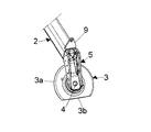
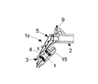
最初に、図1〜図4を参照して、ビードブレーカーグループ又はヘッド1が図示されている。ヘッド1は、例えば、突出する工具保持アーム2と、例えば、工具保持アーム2の先端に遊転自在に取付けられたローラのような、ほぼ平坦な要素によって形成されたビードブレーカー工具3とによって構成された少なくとも一つの支持部品を備える。工具保持アーム2は、使用時に、長手軸をビード落としがなされるべきタイヤ付きホイールの主軸、すなわち回転軸に対して垂直にして延びている。
Initially, with reference to FIGS. 1-4, a bead breaker group or
ローラプレート要素3は、広い周方向縁部3aを有すると共に、セグメント部(円弧部)又はセグメント(円弧)を除外するという意味で、断面が出るように切断され、すなわち切り取られ、そこで、ほぼ直線的な当接フロント3bを画成している。工具3は、工具搬送アーム2によって結局は担持された固定ピン4の回りに(適宜な形態で)回転自在に取付けられている。その結果、ピン4から周方向縁部3aの距離は、ピン4と当接フロント3bの間の距離より大きい。
The
構造的には、工具搬送アーム2は、中空であり得、好ましくは、その先端で適宜にそれに固定されたブラケット5であって、任意の適した方法で、例えば、U字形断面の中間部5aと、工具搬送アーム2の自由端内に挿入されることを意図した取付けシャンク端6(図4)と、ピン4を担持する他端7とを有するブラケット5を担持している。ピン4は、好ましくは、単一のピースで、ブラケット5(図4)と一体的に作られており、工具保持アーム2の長手軸に対しての傾斜軸x−x、例えば傾斜角45°に向けられており、使用中は、ビード落としがなされるべきタイヤ付きホイールの主軸に対しても傾斜している。そのような場合、工具3は、減摩手段、典型的には一つ以上の軸受8の介在によってピン4上に取付けられている。
Structurally, the
工具保持アーム2は、以下にさらに説明するように、回転自在なホイール保持テーブル及び立設サポート、すなわちコラムを装備するタイヤ取付け/取外し機に装着可能であり、伸縮自在のアーム又はいくつかの間接接合部を持つアームであり得、いずれにしてもホイール保持テーブルの回転軸にほぼ直角な面内で移動することができる。
The
所望ならば、工具保持アーム2は、ビードブレーカーグループを手動で移動又は操作する制御ハンドル等が固定される横方向に突き出た耳状要素9を有する。
このビードブレーカーグループの一つにおける動作は、全く簡単である。
If desired, the
Operation in one of these bead breaker groups is quite simple.
ビード落としがなされるべきタイヤ付きホイールをタイヤ取付け/取外し機の回転自在なホイール保持テーブルに固定した後で、操作者は、ビードブレーカー工具3が、ホイールのタイヤの側面及びリムの各フランジの直上、すなわち、どんな場合でもそれらの近くになるようにアーム2を移動する。この点において、ビードブレーカー工具3は、リムのフランジまで移動すると共に、当接フロント3bで、タイヤの隣接側面に対して当接、すなわち若干押し付けられた位置に維持される。
After fixing the wheel with the tire to be beaded on the rotatable wheel holding table of the tire mounting / removing machine, the operator can connect the
操作者は、次に、ホイール保持テーブルの回転を制御して、タイヤとビードブレーカー3の間の摩擦により、ビードブレーカー工具はタイヤと共に回転し、その結果、その周方向部3aは、リムのフランジとタイヤのビードの間に係合されると共に突き刺さること、すなわち、角度をもって突入移動することになり、ホイールのビード落としを開始する。ビード落とし完了時に、角度をもった後退移動によって工具を外すためには、以前の回転方向とは反対の方向にホイール搬送テーブルを一時的に回転させれば十分である。
The operator then controls the rotation of the wheel holding table so that the friction between the tire and the
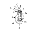
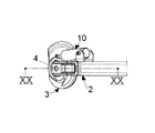
図5〜図8には、図1〜図4を参照して記載されたものと全く同じビードブレーカーグループ1aが図示されている。しかし、このビードブレーカーグループは、アクチュエータ手段、例えば、シリンダ10aが工具保持アーム2に、好ましくは、フォークブラケット11によって関節接合されると共に、ステム10bが縁部3aによって定められた区域において所定の位置にビードブレーカー工具3に関節接合されている二重効用気圧ジャッキ10を備える。
5 to 8 show the same
このビードブレーカーグループの一つにおける作用としては、前述した例にあるように進展するが、工具3を移動させて、当接フロント3bをリムのフランジに当接させた(まず、ジャッキ10のステム10bを引っ込めた)後で、ステム10bを伸長して、続いて工具3を強制回転させ、これにより、工具3がタイヤとリムの間に突き刺さることになって、ビード落としが始まる。次いで、タイヤ付きホイールが回転し、ビード落とし動作の完了時に、ステム10bは、逆戻りするように作動し、その結果、工具3はリムとタイヤのビードの双方から外れ、その後、ビードブレーカーグループは、ビード落としがなされたホイールから離れる。
The operation of one of the bead breaker groups proceeds as in the above-described example, but the
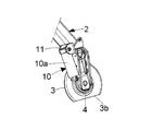
図9〜図12においては、工具3において、弾性戻し手段、例えば、つる巻きバネ12を装備するビードブレーカーグループ1bが、代わりに図示されている。つる巻きバネ12は、バネ12の作動により工具3の回転がサポート部品に対して反対になるように、一方の側がピン13に固定されて、結局はブラケット5に固定され、他方の側が(例えば、ピン14によって)ビードブレーカー工具3に固定される。
9-12, in the
上記のように、工具3を移動してそれ自体の係合フロント3bをリムのフランジ且つタイヤの側面の双方に当接させた後で、ホイール保持テーブルが時計回り方向に回転され、これにより、工具を回転且つ突き刺し、バネ12の動作に対抗させる。ビード落とし完了時に、ホイール保持テーブルの停止動作を行うことによって、バネ12が工具3を待機位置、すなわちタイヤのビードとリムの双方から外れる位置に移動させる。その結果、ビードブレーカーグループを、今ビード落としがなされたホイールから離れるように移動することができる。
As described above, after moving the
図13〜図16には、図5〜図8に参照されたものと同じビードブルーカーグループ1cが、代わりに図示されている。しかし、このビードブレーカーグループは、カウンターローラ要素15のような減摩要素を有する。この減摩要素は、その面が、使用時に、ビード落としがなされるべきタイヤの側面に対向して回転する工具3に遊転自在に且つ同軸的に取付けられている。
In FIGS. 13-16, the same bead
さらに、工具3は、上記の実施形態に係る工具の構造とは若干異なる構造を有しており、特に、揺動アームとして構成されると共に、先端3cとして形状付けられた係合/突き刺し区域と、直線的なセグメント3dとして構成されると共に、一方を係合区域3cの一方の側及び他方を区域3cの他方の側に配置した二つの横方向当接フロントを有する。
Furthermore, the
また、このグループについては、係合フロント3d及びピン4の間の距離が、ピン4と係合/突き刺し区域3c間の距離より短い。
Also, for this group, the distance between the
それにもかかわらず、図5から図8を参照してほぼ同じように説明されるこの工具の機能は、ビード落とし作業中に、カウンターローラ要素15は、タイヤによって回転駆動され、タイヤ及び工具の間の摩擦を低減する。
Nevertheless, the function of this tool, which is explained in much the same way with reference to FIGS. 5 to 8, is that during the bead dropping operation, the
このようなカウンターロータ要素15がない場合は、操作者は、タイヤ付きホイールを外す前に、種々の作業動作中のタイヤに対する工具のすべり(取付け又はビード落とし)を容易にするためにタイヤの部分にグリースを薄く塗り広げなければならない。
In the absence of such a
図17〜図22において、上記のものと大変類似したビードブレーカーグループ1dが図示されている。ただし、工具が、区域3cよりも大きく拡がった係合/突き刺し区域3eと、ほぼ平行な二つの当接フロント3fとを有する。また、このグループについては、当接フロント3fとピン4の間の距離は、ピン4と係合/突き刺し区域3dの間の距離より短い。
17-22, a
一方、図23〜図28は、図17〜図22に図示されたものと同じであるが、アクチュエータ10に代えてつる巻きバネ12が設けられているビードブレーカーグループ1eを図示している。
On the other hand, FIGS. 23 to 28 show the
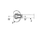
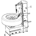
最後に、図29及び図30を参照して、コラムCが上方に延びているホイール保持テーブル用のサポート基部Bを有するタイヤ取付け/取外し機を図示する。この機械はまた、他の(図示された例では、二つの)工具保持アームを提供する。これらの工具保持アームの少なくとも一つは本発明の要旨のものと同じようにビードブレーカーグループを支持する。 Finally, referring to FIGS. 29 and 30, a tire attachment / detachment machine having a support base B for a wheel holding table with a column C extending upwards is illustrated. The machine also provides other (in the illustrated example, two) tool holding arms. At least one of these tool holding arms supports the bead breaker group in the same manner as the subject matter of the present invention.
本発明に係るビードブレーカーグループによれば、今までに提案されたグループに対してより簡便に且つより迅速にビード落とし操作を行うことができることが分かる。実際、操作者は、タイヤ付きホイールをテーブルに取付けた後で、(垂直コラムと垂直回転軸を持つホイール保持器を有する機械に対して)タイヤの直上にグループを移動して、工具がその当接前側区域においてタイヤの側面に当接するまで、グループをタイヤに接近させ、代わりに、係合/突き刺し区域は、タイヤの側面それ自体に対して持ち上げられる。テーブルを回転することにより、又はアクチュエータを駆動することにより、リムの縁部の下方に挿入されると共にタイヤとリムの間に突き刺しされる工具が回転する(特に図22及び図28を参照)。 According to the bead breaker group according to the present invention, it can be seen that the bead dropping operation can be performed more easily and more quickly with respect to the groups proposed so far. In fact, after attaching the tired wheel to the table, the operator moves the group directly over the tire (for machines with wheel retainers with vertical columns and vertical axes of rotation) so that the tool hits it. The group is brought closer to the tire until it abuts the side of the tire in the front side area, instead the engaging / piercing area is raised relative to the side of the tire itself. By rotating the table or driving the actuator, the tool inserted below the edge of the rim and pierced between the tire and the rim is rotated (see particularly FIGS. 22 and 28).
したがって、今までに提案されたビードブレーカーグループと異なり、操作者が工具をテーブルの軸方向に交わるように且つ軸それ自体に向かって移動するように制御する必要がなく、しかし、工具をテーブルの軸に平行に移動するように制御するだけでよいということが分かる。そして、工具のこの構成により、工具自体がタイヤとリムの間に(アクチュエータが設けられていなければ、自動的に)突き刺さることができる。 Thus, unlike the previously proposed bead breaker group, the operator does not need to control the tool to cross the table axially and to move toward the axis itself, but the tool is It can be seen that it only needs to be controlled to move parallel to the axis. This configuration of the tool allows the tool itself to pierce between the tire and the rim (automatically if no actuator is provided).
当業者は、タイヤ取付け/取外し機がまた、本発明に係る他のビードブレーカーグループ、例えば、タイヤの(使用時は、上部及び下部の)各側面に同時にビード落としを行うように意図された一対を装備することができることが分かる。 Those skilled in the art will recognize that the tire loader / unloader is also intended to perform bead drop on other side of the bead breaker group according to the present invention, for example, on each side of the tire (upper and lower in use) simultaneously. You can see that you can equip
ビードブレーカーグループは、垂直回転軸を持つホイール保持テーブルを有する機械に対して記載されているが、同様のことが、水平な回転軸、又は垂直に対して傾斜した回転軸を持つホイール保持テーブルを有する機械に対して考慮される。 The bead breaker group is described for machines having a wheel holding table with a vertical rotation axis, but the same applies to a wheel holding table with a horizontal rotation axis or a rotation axis inclined relative to the vertical. Considered for machines that have.
上記ビードブレーカーグループは、特許請求の範囲によって規定された保護範囲内で多くの修正及び変形を行うことができる。 The bead breaker group can make many modifications and variations within the scope of protection defined by the claims.
2、5 サポート
3 工具
3a、3c、3e 係合/突き刺し区域(engagement−penetration zone)
3b、3d、3f 当接フロント(abutment front)
4 ピン
2, 5
3b, 3d, 3f Abutment front
4 pin
Claims (16)
前記ビードブレーカー工具は、ほぼ平坦であり、
−ビード落としがなされるタイヤ付きホイールのリムのフランジに対して当接フロント(3b、3d、3f)として構成された少なくとも一つの周縁部分と、
−前記ピン(4)とほぼ同軸的な湾曲した周縁部を有し、リムのフランジとビード落としがなされるタイヤのビードの間の係合/突き刺し区域(3a、3c、3e)として作動するように意図された少なくとも一つの部分とを備え、
前記当接フロント(3b、3d、3f)と前記ピン(4)の間の距離は、前記ピン(4)と前記少なくとも一つの係合/突き刺し区域(3a、3c、3e)の間の距離より短いことを特徴とするビードブレーカーグループ。 A bead breaker group for removing a bead of a tire wheel equipped with a rim having a bead engaging flange, the bead breaker group being supported by a support (2, 5) and the support (2, 5) A bead breaker group comprising at least one bead breaker tool (3) mounted to rotate about a pin (4)
The bead breaker tool is substantially flat;
-At least one peripheral portion configured as an abutment front (3b, 3d, 3f) against the flange of the rim of the wheel with tire to which the bead is dropped;
-Having a curved periphery substantially coaxial with said pin (4) and acting as an engagement / piercing area (3a, 3c, 3e) between the rim flange and the bead drop of the tire bead And at least one part intended for
The distance between the abutment front (3b, 3d, 3f) and the pin (4) is greater than the distance between the pin (4) and the at least one engagement / piercing area (3a, 3c, 3e). A short bead breaker group.
a)リム及びタイヤを有するタイヤ付きホイールをホイール保持テーブル上に予め配置し、
b)ビード落としがなされるべきタイヤ付きホイールのリムのフランジに対して当接する当接フロント(3b、3d、3f)として構成される前記少なくとも一つの部分を移動させるようにビードブレーカーグループを移動し、
c)前記ホイール保持テーブルを回転させて、前記リムのフランジと前記タイヤのビードの間の係合/突き刺し区域(3a、3c、3e)の結果として生じる係合/突き刺しによる前記工具の駆動による回転を生じさせる各ステップを含むことを特徴とする方法。 In the method of performing the bead dropping of the tire of the tire-equipped wheel by the tire attaching / detaching machine according to claim 11,
a) A tire-equipped wheel having a rim and a tire is previously placed on a wheel holding table,
b) moving the bead breaker group so as to move the at least one part configured as an abutment front (3b, 3d, 3f) abutting against the flange of the rim of the wheel with tire to be bead dropped; ,
c) Rotation of the wheel holding table by rotation of the tool by engagement / piercing resulting from the engagement / piercing area (3a, 3c, 3e) between the rim flange and the tire bead. A method comprising the steps of:
a)タイヤ及びリムを含むタイヤ付きホイールをホイール保持テーブル上に予め配置し、
b)ビード落としがなされるべきタイヤ付きホイールのリムのフランジに対して当接する当接フロント(3b、3d、3f)として構成される前記少なくとも一つの部分を移動させるようにビードブレーカーグループを移動し、
c)前記リムの前記フランジと前記タイヤのビードの間の前記工具の角度係合/挿入移動を作動させるべく少なくとも一つのアクチュエータ手段を駆動し、
d)前記ホイール保持テーブルを回転する各ステップを含むことを特徴とする方法。 In the method of performing bead dropping of a tire by the tire attaching / detaching machine according to claim 14,
a) A tire-equipped wheel including a tire and a rim is previously arranged on a wheel holding table,
b) moving the bead breaker group so as to move the at least one part configured as an abutment front (3b, 3d, 3f) abutting against the flange of the rim of the wheel with tire to be bead dropped; ,
c) driving at least one actuator means to actuate the angular engagement / insertion movement of the tool between the flange of the rim and the bead of the tire;
d) A method comprising the steps of rotating the wheel holding table.
Applications Claiming Priority (2)
| Application Number | Priority Date | Filing Date | Title |
|---|---|---|---|
| ITVR2008A000050 | 2008-04-28 | ||
| IT000050A ITVR20080050A1 (en) | 2008-04-28 | 2008-04-28 | BREAKER GROUP FOR A TIRE CHANGER MACHINE |
Publications (3)
| Publication Number | Publication Date |
|---|---|
| JP2009262929A JP2009262929A (en) | 2009-11-12 |
| JP2009262929A5 JP2009262929A5 (en) | 2012-05-31 |
| JP5404162B2 true JP5404162B2 (en) | 2014-01-29 |
Family
ID=40297439
Family Applications (1)
| Application Number | Title | Priority Date | Filing Date |
|---|---|---|---|
| JP2009108450A Expired - Fee Related JP5404162B2 (en) | 2008-04-28 | 2009-04-27 | Bead breaker group for tire installation / removal machines |
Country Status (6)
| Country | Link |
|---|---|
| US (1) | US8464774B2 (en) |
| EP (1) | EP2113403B1 (en) |
| JP (1) | JP5404162B2 (en) |
| CN (1) | CN101570118B (en) |
| ES (1) | ES2410262T3 (en) |
| IT (1) | ITVR20080050A1 (en) |
Families Citing this family (9)
| Publication number | Priority date | Publication date | Assignee | Title |
|---|---|---|---|---|
| US8985178B1 (en) | 2010-04-23 | 2015-03-24 | Hunter Engineering Company | Tire bead breaker device and methods for automated tire changer machine |
| ITMO20120206A1 (en) * | 2012-09-04 | 2014-03-05 | M & B Engineering S R L | TANK MACHINE |
| JP6357446B2 (en) * | 2015-05-26 | 2018-07-11 | 小野谷機工株式会社 | Tire attachment / detachment method |
| IT201600111370A1 (en) * | 2016-11-04 | 2018-05-04 | Nexion Spa | APPARATUS FOR MOUNTING AND DISASSEMBLING A TIRE |
| CN108569089A (en) * | 2017-03-09 | 2018-09-25 | 科维(营口)工业有限公司 | A kind of tyre-pressing disc positioning device and tire changer |
| IT201700028239A1 (en) * | 2017-03-14 | 2018-09-14 | Nexion Spa | TOOL FOR TIRE CHANGER MACHINE |
| IT201800009322A1 (en) | 2018-10-10 | 2020-04-10 | Butler Eng And Marketing Spa | MACHINE FOR ASSEMBLY AND / OR DISASSEMBLY OF VEHICLE WHEELS, IN PARTICULAR TRUCK WHEELS |
| CN110126557A (en) * | 2019-05-23 | 2019-08-16 | 营口大力汽保设备科技有限公司 | A kind of lower operating head device of changer dismounting |
| CN114801604B (en) * | 2022-04-15 | 2023-08-01 | 伺轮智能机器人(南京)有限公司 | Method and device for detecting separation state of tire and rim |
Family Cites Families (13)
| Publication number | Priority date | Publication date | Assignee | Title |
|---|---|---|---|---|
| US3032095A (en) * | 1959-01-30 | 1962-05-01 | Big Four Ind Inc | Tire demounting apparatus |
| CH573319A5 (en) * | 1972-06-16 | 1976-03-15 | Duquesne Victor | |
| JPS5174303A (en) * | 1974-12-23 | 1976-06-28 | Yamada Yuki Seizo Co Ltd | TAIYA HAZUSHIKI |
| FR2391864A1 (en) * | 1976-10-06 | 1978-12-22 | Michelin & Cie | TIRE ASSEMBLY / DISASSEMBLY MACHINE |
| USRE33892E (en) * | 1987-04-15 | 1992-04-21 | Freezone Pty Ltd | Tire bead breaker |
| US4939941A (en) * | 1988-09-09 | 1990-07-10 | Coats Wheel Balancer Corp. | Combined distance and diameter measuring apparatus for wheel balancing machine |
| ITVR20010124A1 (en) | 2001-11-22 | 2003-05-22 | Butler Enrineering & Marketing | Bead breaker head with nail for assembly / disassembly of a tire for tire changer machine. |
| ITVR20020060A1 (en) * | 2002-05-29 | 2003-12-01 | Butler Eng & Marketing | TIRE CHANGER ASSEMBLING MACHINE |
| ITRE20020068A1 (en) * | 2002-09-13 | 2004-03-14 | Corghi Spa | AUTOMATIC SIMPLIFIED DEVICE FOR DISASSEMBLY |
| US7355687B2 (en) * | 2003-02-20 | 2008-04-08 | Hunter Engineering Company | Method and apparatus for vehicle service system with imaging components |
| ITVR20040055A1 (en) * | 2004-04-09 | 2004-07-09 | Butler Eng & Marketing | AUTOMATIC FEELER FOR TIRE MOUNTING MACHINES |
| ITMO20040205A1 (en) * | 2004-08-03 | 2004-11-03 | Sicam Srl | 'MACHINE PERFECTED FOR THE MOTORCYCLE AND DISASSEMBLY OF TIRES OF VEHICLE WHEELS'. |
| ITVR20050037A1 (en) | 2005-03-23 | 2006-09-24 | Butler Eng & Marketing | TOOL FOR AUTOMATIC ASSEMBLY / DISASSEMBLY OF A TIRE ON / FROM A RIM |
-
2008
- 2008-04-28 IT IT000050A patent/ITVR20080050A1/en unknown
-
2009
- 2009-04-07 US US12/419,743 patent/US8464774B2/en active Active
- 2009-04-24 ES ES09158682T patent/ES2410262T3/en active Active
- 2009-04-24 EP EP09158682A patent/EP2113403B1/en active Active
- 2009-04-27 JP JP2009108450A patent/JP5404162B2/en not_active Expired - Fee Related
- 2009-04-28 CN CN2009101369489A patent/CN101570118B/en not_active Expired - Fee Related
Also Published As
| Publication number | Publication date |
|---|---|
| ITVR20080050A1 (en) | 2009-10-29 |
| EP2113403B1 (en) | 2013-03-27 |
| CN101570118A (en) | 2009-11-04 |
| US20090266493A1 (en) | 2009-10-29 |
| CN101570118B (en) | 2013-03-06 |
| US8464774B2 (en) | 2013-06-18 |
| JP2009262929A (en) | 2009-11-12 |
| EP2113403A1 (en) | 2009-11-04 |
| ES2410262T3 (en) | 2013-07-01 |
Similar Documents
| Publication | Publication Date | Title |
|---|---|---|
| JP5404162B2 (en) | Bead breaker group for tire installation / removal machines | |
| EP2468541B1 (en) | Device for demounting the second bead of a tire from a rim and respective demounting method | |
| JP4519984B2 (en) | Tire changer for industrial vehicle wheels | |
| JP4185781B2 (en) | Bead removal and tire removal device | |
| EP2524821B1 (en) | Device for the automatic demounting of a tire from a rim and machine equipped with such device | |
| US8910693B2 (en) | Device for demounting a tire from a rim as well as a tire demounting machine equipped with such device | |
| EP1714807B2 (en) | Tool for automatically assembling or disassembling a tyre to/from a wheel rim | |
| JP4073299B2 (en) | Bead removal head for tire attachment / detachment device | |
| EP2629992B1 (en) | A tyre demounting machine | |
| JP5478024B2 (en) | Bead press device for tire attaching / detaching device | |
| JP5563742B2 (en) | Mount press device for tire attaching / detaching device | |
| EP1897709B1 (en) | Machine for fitting and removing vehicle tyres | |
| JP2009227006A (en) | Tire bead guide device for tire mounting/demounting apparatus | |
| JP2012131477A5 (en) | ||
| JP2009262929A5 (en) | ||
| US9126463B2 (en) | Bead breaker group for a tire mounting-demounting machine | |
| CN111016557B (en) | Machine for mounting and/or dismounting vehicle wheels, in particular truck wheels | |
| WO2022033203A1 (en) | Combined tire dismounting device and large horizontal tire changer |
Legal Events
| Date | Code | Title | Description |
|---|---|---|---|
| A521 | Request for written amendment filed |
Free format text: JAPANESE INTERMEDIATE CODE: A523 Effective date: 20120404 |
|
| A621 | Written request for application examination |
Free format text: JAPANESE INTERMEDIATE CODE: A621 Effective date: 20120404 |
|
| A977 | Report on retrieval |
Free format text: JAPANESE INTERMEDIATE CODE: A971007 Effective date: 20130926 |
|
| TRDD | Decision of grant or rejection written | ||
| A01 | Written decision to grant a patent or to grant a registration (utility model) |
Free format text: JAPANESE INTERMEDIATE CODE: A01 Effective date: 20131001 |
|
| A61 | First payment of annual fees (during grant procedure) |
Free format text: JAPANESE INTERMEDIATE CODE: A61 Effective date: 20131029 |
|
| R150 | Certificate of patent or registration of utility model |
Ref document number: 5404162 Country of ref document: JP Free format text: JAPANESE INTERMEDIATE CODE: R150 |
|
| R250 | Receipt of annual fees |
Free format text: JAPANESE INTERMEDIATE CODE: R250 |
|
| R250 | Receipt of annual fees |
Free format text: JAPANESE INTERMEDIATE CODE: R250 |
|
| R250 | Receipt of annual fees |
Free format text: JAPANESE INTERMEDIATE CODE: R250 |
|
| R250 | Receipt of annual fees |
Free format text: JAPANESE INTERMEDIATE CODE: R250 |
|
| R250 | Receipt of annual fees |
Free format text: JAPANESE INTERMEDIATE CODE: R250 |
|
| LAPS | Cancellation because of no payment of annual fees |