JP4836247B2 - Tire removal machine - Google Patents
Tire removal machine Download PDFInfo
- Publication number
- JP4836247B2 JP4836247B2 JP2006081122A JP2006081122A JP4836247B2 JP 4836247 B2 JP4836247 B2 JP 4836247B2 JP 2006081122 A JP2006081122 A JP 2006081122A JP 2006081122 A JP2006081122 A JP 2006081122A JP 4836247 B2 JP4836247 B2 JP 4836247B2
- Authority
- JP
- Japan
- Prior art keywords
- tool
- tire
- wheel rim
- arm
- wheel
- Prior art date
- Legal status (The legal status is an assumption and is not a legal conclusion. Google has not performed a legal analysis and makes no representation as to the accuracy of the status listed.)
- Active
Links
- 239000011324 bead Substances 0.000 claims description 34
- 238000012546 transfer Methods 0.000 claims description 20
- 238000013519 translation Methods 0.000 claims description 7
- 239000000463 material Substances 0.000 claims description 4
- 239000004033 plastic Substances 0.000 claims description 2
- 238000000034 method Methods 0.000 description 12
- 210000000078 claw Anatomy 0.000 description 5
- 238000013459 approach Methods 0.000 description 4
- XEEYBQQBJWHFJM-UHFFFAOYSA-N Iron Chemical compound [Fe] XEEYBQQBJWHFJM-UHFFFAOYSA-N 0.000 description 2
- 238000004519 manufacturing process Methods 0.000 description 2
- 230000002860 competitive effect Effects 0.000 description 1
- 230000008602 contraction Effects 0.000 description 1
- 239000003365 glass fiber Substances 0.000 description 1
- 229910052742 iron Inorganic materials 0.000 description 1
- 229910001092 metal group alloy Inorganic materials 0.000 description 1
- 229920001778 nylon Polymers 0.000 description 1
- 239000012783 reinforcing fiber Substances 0.000 description 1
- 238000011160 research Methods 0.000 description 1
Images


Classifications
-
- B—PERFORMING OPERATIONS; TRANSPORTING
- B60—VEHICLES IN GENERAL
- B60C—VEHICLE TYRES; TYRE INFLATION; TYRE CHANGING; CONNECTING VALVES TO INFLATABLE ELASTIC BODIES IN GENERAL; DEVICES OR ARRANGEMENTS RELATED TO TYRES
- B60C25/00—Apparatus or tools adapted for mounting, removing or inspecting tyres
- B60C25/01—Apparatus or tools adapted for mounting, removing or inspecting tyres for removing tyres from or mounting tyres on wheels
- B60C25/05—Machines
- B60C25/132—Machines for removing and mounting tyres
- B60C25/135—Machines for removing and mounting tyres having a tyre support or a tool, movable along wheel axis
- B60C25/138—Machines for removing and mounting tyres having a tyre support or a tool, movable along wheel axis with rotary motion of tool or tyre support
-
- B—PERFORMING OPERATIONS; TRANSPORTING
- B60—VEHICLES IN GENERAL
- B60C—VEHICLE TYRES; TYRE INFLATION; TYRE CHANGING; CONNECTING VALVES TO INFLATABLE ELASTIC BODIES IN GENERAL; DEVICES OR ARRANGEMENTS RELATED TO TYRES
- B60C25/00—Apparatus or tools adapted for mounting, removing or inspecting tyres
- B60C25/01—Apparatus or tools adapted for mounting, removing or inspecting tyres for removing tyres from or mounting tyres on wheels
- B60C25/05—Machines
- B60C25/0563—Tools interacting with the tyre and moved in relation to the tyre during operation
- B60C25/0578—Tools interacting with the tyre and moved in relation to the tyre during operation hooking only
-
- B—PERFORMING OPERATIONS; TRANSPORTING
- B60—VEHICLES IN GENERAL
- B60C—VEHICLE TYRES; TYRE INFLATION; TYRE CHANGING; CONNECTING VALVES TO INFLATABLE ELASTIC BODIES IN GENERAL; DEVICES OR ARRANGEMENTS RELATED TO TYRES
- B60C25/00—Apparatus or tools adapted for mounting, removing or inspecting tyres
- B60C25/01—Apparatus or tools adapted for mounting, removing or inspecting tyres for removing tyres from or mounting tyres on wheels
- B60C25/05—Machines
- B60C25/0563—Tools interacting with the tyre and moved in relation to the tyre during operation
- B60C25/0584—Predetermined tool path, e.g. coulisse, multi-link
Landscapes
- Engineering & Computer Science (AREA)
- Mechanical Engineering (AREA)
- Tires In General (AREA)
- Automatic Assembly (AREA)
- Automobile Manufacture Line, Endless Track Vehicle, Trailer (AREA)
- Heating, Cooling, Or Curing Plastics Or The Like In General (AREA)
- Tyre Moulding (AREA)
- Moulds For Moulding Plastics Or The Like (AREA)
Abstract
Description
本発明は、タイヤをホイールリムへ/から自動的に着脱する工具に関する。周知のように、所要のビード離脱操作の終了後に、タイヤ付きホイールのタイヤをその対応するホイールリムから正しく取り外すために、まずフック型着脱工具をタイヤとホイールリムとの間の接触部位に挿入し、工具を接触部位に打ち込み、それによって、タイヤビードがホイールリム縁から離され、かつ工具フックがタイヤビードの縁と係合することが可能になる。 The present invention relates to a tool for automatically attaching / detaching a tire to / from a wheel rim. As is well known, after the required bead disengagement operation has been completed, a hook-type removal tool is first inserted into the contact area between the tire and the wheel rim in order to correctly remove the tire of the tired wheel from its corresponding wheel rim. The tool is driven into the contact site, thereby separating the tire bead from the wheel rim edge and allowing the tool hook to engage the edge of the tire bead.
次に工具を取り外し、したがってそれと共にビードの縁を、それがホイールリム縁を越えて延ばされるまで引っ張り、そして最後にホイールリム又は工具を回転させて、タイヤビード全体をホイールリム縁を越えて徐々に押しやることが必要である。逆順での同様のより簡単な操作を、タイヤを取り付けるために実施する必要がある。 Then remove the tool, and therefore pull the bead edge with it until it extends beyond the wheel rim edge, and finally rotate the wheel rim or tool to gradually move the entire tire bead past the wheel rim edge. It is necessary to push it. Similar simpler operations in reverse order need to be performed to install the tire.
しかしながら、このような着脱操作は、ホイールリム(これは多くの場合軽金属合金から作られる)及びタイヤが損傷を受けるか、又は単に掻き傷を付けられることを防止するために、実行の適正な確かさを必要とする。 However, such a detachment operation can be performed properly to prevent the wheel rim (which is often made from light metal alloys) and the tire from being damaged or simply scratched. Need
非常に多数の着脱技術が提案されており、広範な研究がこの問題の解決法を見つけるために長期にわたって行われてきた。したがって、例えば、特許文献1は、ホイールリムを支える回転手段と、タイヤを着脱する自動装置とを備えるタイヤ着脱機を記載している。
A large number of attachment / detachment techniques have been proposed and extensive research has been conducted over time to find a solution to this problem. Therefore, for example,
このような自動装置は一端が張り出し式に延びるアームを有している。このアームは、フック型組立工具をその自由端で支持する回転支持手段に配置されたホイールリムに対して半径方向かつ軸方向の両方向に動くことが可能であり、組立工具はその先端部で連接され、それによってアームに対して横に延びる。 Such an automatic device has an arm with one end extending in a protruding manner. The arm is movable in both radial and axial directions relative to a wheel rim arranged on a rotational support means for supporting the hook-type assembly tool at its free end, and the assembly tool is articulated at its tip. Thereby extending laterally with respect to the arm.
組立工具は、複動ジャッキによって制御されるリンケージ装置によって、その回転軸を中心とする角運動を生じるように制御され得る。初めに、工具は高い位置に設置され、そのフック端がタイヤとホイールリムとの間の部位に接触するまで、支持アームによって下げられ、そしてタイヤビードは下方へ押される。同時に、工具は、そのフック型自由端がホイールリムに近づく方向に、その連接ピンを中心として角度αまで回転させる。 The assembly tool can be controlled to produce angular motion about its axis of rotation by a linkage device controlled by a double-acting jack. Initially, the tool is placed in a high position, lowered by the support arm until its hook end contacts the site between the tire and the wheel rim, and the tire bead is pushed downward. At the same time, the tool is rotated to an angle α about the connecting pin in the direction in which the hook-type free end approaches the wheel rim.
このような回転は、タイヤビードが工具のフック型端によって引っ掛けられるのに役立つ。この時点で、工具搬送アームは上方へ動かされ、したがって工具は、それがホイールリム縁を越えて延ばされるまで、それと共にタイヤビードを動かす。 Such rotation helps the tire bead to be hooked by the hook end of the tool. At this point, the tool transfer arm is moved upwards, so the tool moves the tire bead with it until it is extended beyond the wheel rim edge.
次に、ホイールリムは、工具のフック部分に沿って摺動しながら、タイヤビードがホイールリム縁の外へ徐々に動かされるように回転させられる。必要なら、この後の工程で、工具はフック縁がホイールリムから離れる方向に角度βまで回転させることが可能であり、それによってビードを引き出すのに役立つ。 The wheel rim is then rotated so that the tire bead is gradually moved out of the wheel rim edge while sliding along the hook portion of the tool. If necessary, in a later step, the tool can be rotated to an angle β in a direction away from the wheel rim, thereby helping to pull out the bead.
全ての取り外し工程で、工具のそのフック背部はホイールリムに面しているのに対して、フック部分本体はタイヤに面している。しかしながら、工具は自由ではなくて、それは、タイヤをその制御リンケージから取り外すのに必要である全工程中、所定の位置に押し込まれ、しっかりと保持される。
明らかに、このような技術的解決法は、一方で、実行するのに大変費用がかかり、他方で、着脱工程中にホイールリム及び/又はタイヤを損傷するのを避けるために熟練した操作者を必要とする。 Obviously, such a technical solution, on the one hand, is very expensive to carry out, and on the other hand requires skilled operators to avoid damaging the wheel rim and / or tire during the detachment process. I need.
特許文献2は、特許文献1に記載されているものに、全く類似した着脱工具の特定の実施形態を開示している。特許文献3は、後部支持直立材に近づくか、又はそれから離れるように動かされ得る回転ホイール搬送テーブルと、タイヤ着脱装置とを備えるタイヤ着脱機を開示している。
U.S. Patent No. 6,057,028 discloses a specific embodiment of a detachable tool that is quite similar to that described in U.S. Patent No. 6,057,059.
着脱装置は、支持直立材に平行なガイド部材に沿って、摺動可能なスリーブによって支持される。工具搬送ブシュの耳がスリーブに連接されている。工具は、フック形端部付きの鉄棒によって形成されている。この鉄棒は、ブシュ内で回転するように取り付けられ、かつそれがブシュの軸を中心とする角運動を生じ得るように複動ジャッキによって制御され得る。フック形端部付きの鉄棒によって形成される。 The detachable device is supported by a slidable sleeve along a guide member parallel to the support upright. The ear of the tool conveying bush is connected to the sleeve. The tool is formed by a bar with a hook-shaped end. The iron bar is mounted for rotation within the bushing and can be controlled by a double-acting jack so that it can produce angular motion about the bushing axis. It is formed by a horizontal bar with a hook-shaped end.
工具はまず、そのフック形端部がホイールリムに対して接線方向に向けられた状態で、ビードとホイールリム縁との間の部位に押し当てて動かされる。次に、それはタイヤ縁を越えて押し込まれ、工具は約90度まで回転させられて、そのフック形端部がタイヤビードの縁を乗り越え、それに係合することを可能にする。そして最後にタイヤ縁部分が引き出され、続いてホイールは回転させられる。 The tool is first moved against the part between the bead and the wheel rim edge, with its hook-shaped end directed tangential to the wheel rim. It is then pushed over the tire edge and the tool is rotated up to about 90 degrees to allow its hook-shaped end to ride over and engage the edge of the tire bead. Finally, the tire edge is pulled out and then the wheel is rotated.
また、この着脱工具は次に操作者によって制御される機構を用いた操作を必要とする。これは、一方で、工具調整及び制御装置のための多大のコストをもたらす。他方では、ホイールリム又はタイヤに対する工具の状態(特に傾き)についての間違った判定のために失敗する可能性が高く、これによって工具はタイヤ縁にぶつかり、その結果それを損傷するおそれがある。 In addition, this detachable tool requires an operation using a mechanism controlled by the operator. This, on the other hand, results in significant costs for tool adjustment and control devices. On the other hand, it is likely to fail due to an incorrect determination as to the state (especially tilt) of the tool relative to the wheel rim or tire, which may cause the tool to hit the tire edge and consequently damage it.
本発明の主目的は、タイヤ付きホイール又はホイールリムのための回転支持体を備えるタイヤ着脱機に設置されるタイヤ着脱工具を提供することである。この工具は、ホイールの回転支持体への位置決め及び工具調整を除いて、操作者による手動操作無しにタイヤを着脱することを可能にする。 A main object of the present invention is to provide a tire attaching / detaching tool installed in a tire attaching / detaching machine provided with a rotating support for a wheel with wheels or a wheel rim. This tool allows the tire to be attached and detached without manual operation by the operator, with the exception of positioning the wheel on a rotating support and adjusting the tool.
本発明の別の目的は、開始工程中の手動介入は別として、操作者の手動介入が要求されるときに、どんなむだ時間も必要としない製造し使用するのが非常に簡単なタイヤ着脱工具を提供することである。 Another object of the present invention is a tire removal tool that is very simple to manufacture and use, requiring no manual time when manual intervention by the operator is required, apart from manual intervention during the starting process. Is to provide.
本発明の別の目的は、競争力のある製造原価で得られるタイヤ着脱工具を提供することである。 Another object of the present invention is to provide a tire detachment tool obtained at a competitive manufacturing cost.
本発明の第1態様によって、タイヤ付きホイール又はホイールリムを回転可能に支持するように構成されたタイヤ着脱機と共に使用するタイヤ着脱工具が提供され、前記工具は、前記タイヤ着脱機の対応するガイド部材に一端が張り出し式に支持され、前記工具は、前記ホイールの回転軸に平行に延び、前記工具は、前記ガイド部材に摺動可能に取り付けられる工具搬送アームと、少なくとも1つの爪形部材とを備えており、前記爪形部材は、前記支持アームに対する回転並進運動を実行できるように前記支持アームに拘束された第1端部を有しており、前記爪形部材のもう一方の自由端は、フック形であり前記ホイールリムに向いた背部を有している。 According to a first aspect of the present invention, there is provided a tire detachment tool for use with a tire detacher configured to rotatably support a wheel or wheel rim with a tire, the tool being a corresponding guide of the tire detacher. One end is supported in an overhanging manner on the member, the tool extends parallel to the rotational axis of the wheel, the tool is slidably attached to the guide member, and at least one claw-shaped member; The claw-shaped member has a first end constrained by the support arm so as to be able to perform rotational translation with respect to the support arm, and the other free end of the claw-shaped member Is hook-shaped and has a back facing the wheel rim.
前記爪形部材は、その第1端部で前記工具搬送アームに形成された少なくとも1つの凹み又は長穴で連接され、前記凹み又は長穴は工具搬送アームの軸及びそれに垂直な方向の両方に対して傾いた方向に延びることが有利である。 The claw-shaped member is connected at its first end by at least one recess or slot formed in the tool transfer arm, the recess or slot being in both the axis of the tool transfer arm and the direction perpendicular thereto. It is advantageous to extend in an inclined direction.
前記第1端部で、前記爪形部材はリンク又はシャックル部材の端部に連接され、この部材の他端が前記工具搬送アームに連接されることが好ましい。 Preferably, the claw-shaped member is connected to the end of the link or shackle member at the first end, and the other end of the member is connected to the tool transfer arm.
本発明の別の態様によって、前記の少なくとも1つの着脱工具を備えるタイヤ着脱機が提供される。 According to another aspect of the present invention, there is provided a tire detacher including the at least one detachment tool.
このようなタイヤ着脱機はまた、使用中に、前記機械に置かれたホイールリム又はタイヤ付きホイールに関して対向する側に配置される少なくとも1対のビード離脱ローラーと、ホイールリム又はタイヤ付きホイールの軸に平行に、しかも互いに平行で所定の距離だけ隔てた2つの方向に沿って摺動する直立材とを備えることが有利である。 Such a tire remover also includes, in use, at least a pair of bead release rollers disposed on opposite sides with respect to a wheel rim or tired wheel placed on the machine, and a wheel rim or tired wheel shaft. And an upright that slides in two directions parallel to each other and separated by a predetermined distance.
本発明のさらなる特徴及び利点が、添付図面を参照して与えられるそのいくつかの現在の好ましい実施形態についての次の詳細な説明からより明かになるはずである。 Further features and advantages of the present invention will become more apparent from the following detailed description of several presently preferred embodiments thereof, given with reference to the accompanying drawings.
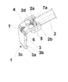
添付図面において、同じ又は類似の部品又は構成要素は、同じ参照数字で表示される。まず、図1〜図6及び図11を参照すると、タイヤPを着脱するための参照番号1で概略示された工具が示されている。工具は工具搬送アーム2を備えており、アーム2はその一端でタイヤ着脱機に設けたサイドガイド13aによって、タイヤに対して半径方向に支持されている。
In the accompanying drawings, the same or similar parts or components are denoted by the same reference numerals. First, referring to FIGS. 1 to 6 and FIG. 11, a tool schematically indicated by
以下にさらに説明されるように、工具1はガイド13aに対して図11のタイヤの軸y−yにほぼ平行な方向に移動できる。アーム2の他端はフォーク形であり、アーム2に平行に延びる2つの側板2a及び2bによって形成された歯を備えている。さらに、フォーク2はシャックル部材4を介して爪形部材3に連接されている。このシャックル部材は、その一端5でフォーク2dの2つの側板2a及び2bに連接され、そしてその他端6で爪形部材3の一端に連接される。
As will be described further below, the
爪形部材3はほぼ板状の形であり、そしてほぼフック形であり、かつ使用中に工具搬送アーム2に向く内側凹み3b及び凹み3bから見て外方に向く外側溝3cの両方を板状部分と共に画定するように構成した横長さ3aで終わる他端(自由端)を有する。
The claw-
それぞれの弾性収縮ばね7及び7aが爪形部材3とシャックル部材4との間に、そしてシャックル部材と工具搬送アーム2との間に設けられている。以下にさらに説明するように、このようなばねは爪形部材3をアーム2に対してほぼ直角の状態に保持するのに適しているのに対して、シャックル部材4はアーム自体にほぼ整列して保持され、各状態が変化した後に戻り部材の機能を果たす。
Respective elastic contraction springs 7 and 7 a are provided between the claw-
工具1は、任意の適した材料、好ましくは減摩プラスチック材料、例えばナイロン(登録商標)から作られることが可能であり、この材料は強化用繊維又は組織、例えばガラス繊維で補強されることが有利である。
The
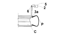
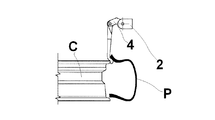
タイヤPのビードが、取り外しプロセスの第1工程中、例えばビード離脱ローラー17及び18を用いて、対応するホイールリムCから離脱された後に、工具1は、工具搬送アーム2を適切に下げることによって、その自由端3a(図2)の外側溝3cがホイールリム縁とタイヤビードとの間の接触部位においてホイールリムCと当接する。
After the bead of the tire P has been released from the corresponding wheel rim C during the first step of the removal process, for example using
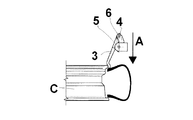
次に、矢印Aによって示すように(図3)、工具搬送アーム2を下げ続ける間に、タイヤビードがフック形端部3cの内側凹み3bで爪に係合するまで(図4)、爪形部材の端部3aはビードとタイヤ縁との間に挿入される。
Next, as indicated by arrow A (FIG. 3), while the
これらの工程中、ホイールリムと外側溝でずっと接触している爪3は、端部3aがホイールリムに接近するような方向にピン6を中心として回転する。これに対して、シャックル部材4は爪の回転方向と同じ回転方向にピン5を中心として回転し、したがってほぼ水平の配置からほぼ垂直の配置へ変化する。このような二重の回転は、本質的に爪3の工具搬送アーム2に対する回転並進運動となる。
During these steps, the
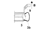
この時点で、工具搬送アーム2は押し上げられる(矢印B、図5)。これによって、工具搬送アーム2に回動自在に取り付けられているシャックル部材4の端部が回転かつ上昇し、爪3に回動自在に取り付けられているシャックル部材4の端部が回転かつ移動する。これらの運動の結果として、一方でシャックル部材4に回動自在に取り付けられ、他方でホイールリム縁と接触している爪3は、端部3aをホイールリムから離すような方向に1回転し、ホイールの軸y−yにほぼ平行な状態に再び達する。
At this point, the
したがって、アーム2を上方へ動かし続けている間に、シャックル部材4は、ばね7aによって制御されてアーム2に対する均衡状態に運ばれ、そしてアーム2のこれ以上のさらなる上方への運動は、シャックル部材4、及びその結果として爪3を上方へ移動させる結果になる。爪3はタイヤビードをそれがタイヤ縁の外側にある状態(図6)に引くのに対して、爪3の自由端3aはホイールリムの隣接する縁にその外側溝3cで摺動自在に係合する。
Thus, while continuing to move the
この時点で、ホイールリム又は工具1を回転させるのに十分になり、それによってタイヤビード全体をホイールリムの上に移動させる。
At this point, it is sufficient to rotate the wheel rim or
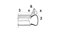
次に、図7〜図10に示す実施形態を参照して、フォーク形端部2dを有する工具搬送アーム2を備えた本発明による装置を示す。この端部2dに1対の対向する長穴8が、工具搬送アームの軸x−xに対して傾いた方向(例えば45度)に延びて形成される。ピン9がこれらの長穴を自由に摺動できる。このようなピンに、前記のものに全く似ている爪形部材3が予め回動自在に取り付けられている。
Next, with reference to the embodiment shown in FIGS. 7 to 10, an apparatus according to the invention with a
このような工具の操作は図1〜図6を参照して説明したものと似ており、工具搬送アーム2は、その下方への運動中、爪3を動かしてホイールリムとフック端部3aの外側溝3cとの間の接触部位でホイールリムに接触させる。次に、アーム2のこれ以上のさらなる下方への運動は、爪3をタイヤビードとタイヤ縁との間に挿入させる。同時にそれは、傾いた長穴8に沿ったピン9の摺動によって、爪3の端部3aは、ホイールリムの内部中央帯により近づく方向に傾けられることになる(図8)。
The operation of such a tool is similar to that described with reference to FIGS. 1 to 6, and the
この時点で、アーム2はそのガイド13aに沿って後方へ動かされ、それによって爪3の状態の変化が得られ、爪はホイールの軸y−yにほぼ平行な状態になる。そしてアームの後方への運動が続いている間に、そのフック形端部3aでビードの内側に係合し、その溝3cがホイールリム縁の上に動かされ(図10)、この位置でタイヤビードはホイールリムの外側へ局部的に押し出される。
At this point, the
そして、タイヤの取り外しを完了するために、ホイール又は工具を回転させればよい。 And in order to complete removal of a tire, what is necessary is just to rotate a wheel or a tool.
なお、前記の工具1を備える図11の着脱機10を特に参照すると、軸y−yを中心としてタイヤが取り付けられるホイールリム、又は対応するタイヤが取り外されるタイヤ付きホイールを回転可能に支持する伸張アーム20〜23を有する自己センタリング装置11が10aで概略を示す基部から立ち上がっている。
In particular, with reference to the
着脱機10は、また1対のビード離脱ローラー17及び18を備えている。これらのローラーの1つ18はガイド13aに沿って摺動自在に取り付けられ、工具搬送アーム2はその上を摺動可能である。これに対して、他のローラー17はガイド13aに平行なガイド13bに摺動自在に取り付けられている。これらのガイドは、着脱機に通常設けられる機械の直立材又は後部支柱13に取り付けられる。
The attachment /
なお、工具搬送アームは、複動ジャッキ130aによって制御されることが可能である。これに対して、ビード離脱ローラー17及び18は、それぞれの複動ジャッキ130b(1つだけ図11に示す)によって、それぞれの摺動ガイドに沿って摺動するように制御される。
The tool transfer arm can be controlled by a double-
ビード離脱ローラー装置17及び18の特有の特徴は、それらのローラーが、回転可能な自己センタリング装置11に対して偏位して取り付けられていることである。すなわち、それらは、平行であるが互いに所定の距離ずれてガイド13a及び13bに摺動自在に取り付けられているので、ホイールリム・タイヤアセンブリに関して対向する側に設置されることになる。このことにより、それらのローラーは、使用中には、タイヤの対向するビードに、しかも爪3に関して対向する側に設置され作用することになる。
A unique feature of the bead
当技術分野で周知のように、制御レバー14もまた、支柱13に拘束され、そして制御押しボタンパネルを担持するノブと、基部に配置した2つのペダル25及び26とを備える。
As is well known in the art, the
ビード離脱ローラーは、支持伸縮アーム15及び16によって一端が張り出し式に支持されることが有利であり、これらのアームは作用するホイールのさまざまな直径にしたがって自動的に伸縮する。
The bead release roller is advantageously supported at one end in an overhanging manner by support
タイヤのホイールリムへの取り付け操作が、部分的に逆の順番で作用する同様の方法で実行される。 The operation of attaching the tire to the wheel rim is carried out in a similar manner, partly in reverse order.
したがって、本発明によるタイヤ着脱装置は、特に熟練した操作者を必要としない。実際のところ、操作者がタイヤを機械の上に置き、次いで、工具がタイヤとホイールリムとの間の接触部位の真上に位置し、かつ外側溝3cがホイールリム縁に設置されるように、工具搬送アームを調整すればよい。このとき、爪が内側凹みでタイヤビードに係合するまで下方へ動くように工具搬送アームを調整し、次いでタイヤビードをホイールリム縁の上に動かすために上方へ動くように工具搬送アームを調整すればよい。
Therefore, the tire attaching / detaching device according to the present invention does not require a particularly skilled operator. In fact, the operator places the tire on the machine, then the tool is located directly above the contact area between the tire and the wheel rim, and the
これらの操作の全ては、適切なソフトウェアと、基部又は機械の支柱に設置され得るプログラム可能な制御ユニットとを用いて完全に自動的に実行してもよい。 All of these operations may be performed fully automatically using appropriate software and a programmable control unit that may be installed in the base or machine column.
したがって、さまざまな取り外し工程の間、爪3の傾きを制御することは必要ではない。取り外し工程では、特定の工具構成によって課せられる回転並進及び傾斜運動を実行することによって、ホイールリム又はタイヤを損傷せずに安全かつ早急な取り外しを可能にする。
Therefore, it is not necessary to control the inclination of the
タイヤを取り外すのに必要な全ての工程中、爪3は外側溝3cでタイヤ部分と接触したままである。図2〜図6の実施形態に示すように、爪3がタイヤビードと係合するのに必要な端部3aのホイールリムに近づく方向における傾きが、爪3の工具搬送アームに対する回転並進運動によって自動的に起きる。このような回転並進運動は、シャックル部材4の回転並びに爪の回転及び並進運動によって確実にされる。
During all the steps necessary to remove the tire, the
これは、図7〜図10の実施形態では、ピン9の長穴8内における並進運動、結果として生じる爪の回転及び端部3aの工具搬送アーム2の端部への接近によって達成される。
This is achieved in the embodiment of FIGS. 7 to 10 by the translational movement of the
前記のタイヤ着脱機及びタイヤ着脱工具は、特許請求の範囲によって規定される範囲内で多数の変更及び改変が可能である。したがって、例えば、工具搬送アーム2は、さまざまなタイヤ付きホイールの直径に適合させる自動的な伸縮運動をするように伸縮自在にすることができる。
The tire attaching / detaching machine and the tire attaching / detaching tool can be changed and modified in many ways within the scope defined by the claims. Thus, for example, the
Claims (14)
前記回転軸(y−y)とほぼ平行に、前記基部から上方に伸びた少なくとも1つのガイド部材(13a)と、
前記ガイド部材(13a)に摺動可能に取り付けられる工具搬送アーム(2)と、
自由端(3a)の一端を有する板状の工具部材(3)と、
前記板状の工具部材(3)の他端である第1端部を、前記工具搬送アーム(2)に連接し、前記工具部材の運動を限定する部材(2a、2b、4、6、7、7a、8、9)とを備えており、
これにより、前記工具部材(3)が前記ホイールリム及び/又は前記ホイールリム上の前記タイヤに接触したときに、前記ホイールリム及び/又は前記ホイールリム上の前記タイヤによる前記工具部材(3)への反力の印加により、前記工具部材(3)の前記工具搬送アーム(2)に対する回転並進運動が可能になり、
前記工具部材(3)の自由端(3a)は、前記ホイールリムに向いた背部を備えるタイヤ取り外し機。 A base (10a) configured to support a wheel or wheel rim with a tire rotatably about a rotation axis (y-y) ;
At least one guide member (13a) extending upward from the base portion substantially parallel to the rotation axis (y-y) ;
A tool transfer arm (2) slidably attached to the guide member (13a) ;
A plate-like tool member (3) having one end of the free end (3a) ;
A member (2a, 2b, 4, 6, 7 ) that connects the first end, which is the other end of the plate-shaped tool member (3) , to the tool transfer arm (2) and limits the movement of the tool member. 7a, 8, 9)
Thus, when the tool member (3) is in contact with the tire on the wheel rim and / or the wheel rim, said tool member by the tire on the wheel rim and / or the wheel rim to (3) by the application of the reaction force of enables rotational translation with respect to the tool-carrying arm (2) of said tool member (3),
The tire removal machine, wherein a free end (3a ) of the tool member (3) includes a back portion facing the wheel rim.
前記弾性的に変形する手段は、前記工具部材(3)と前記シャックル部材(4)との間と、前記シャックル部材(4)と前記工具搬送アーム(2)との間とに設けられ、それによって前記工具部材を前記ホイールリムの回転軸に実質的に平行な向きの静止位置に保持する請求項2に記載のタイヤ取り外し機。 The tool member (3) is connected to one end of a shackle member (4) at the first end, and the other end of the shackle member is connected to the tool transfer arm (2).
The elastically deforming means is provided between the tool member (3) and the shackle member (4) and between the shackle member (4) and the tool transfer arm (2). The tire removing machine according to claim 2 , wherein the tool member is held in a stationary position in a direction substantially parallel to a rotation axis of the wheel rim.
Applications Claiming Priority (2)
| Application Number | Priority Date | Filing Date | Title |
|---|---|---|---|
| ITVR2005A000037 | 2005-03-23 | ||
| IT000037A ITVR20050037A1 (en) | 2005-03-23 | 2005-03-23 | TOOL FOR AUTOMATIC ASSEMBLY / DISASSEMBLY OF A TIRE ON / FROM A RIM |
Publications (3)
| Publication Number | Publication Date |
|---|---|
| JP2006298360A JP2006298360A (en) | 2006-11-02 |
| JP2006298360A5 JP2006298360A5 (en) | 2009-04-09 |
| JP4836247B2 true JP4836247B2 (en) | 2011-12-14 |
Family
ID=36622238
Family Applications (1)
| Application Number | Title | Priority Date | Filing Date |
|---|---|---|---|
| JP2006081122A Active JP4836247B2 (en) | 2005-03-23 | 2006-03-23 | Tire removal machine |
Country Status (8)
| Country | Link |
|---|---|
| US (1) | US7497761B2 (en) |
| EP (1) | EP1714807B2 (en) |
| JP (1) | JP4836247B2 (en) |
| CN (1) | CN1935540B (en) |
| AT (1) | ATE435130T1 (en) |
| DE (1) | DE602006007513D1 (en) |
| ES (1) | ES2329067T5 (en) |
| IT (1) | ITVR20050037A1 (en) |
Families Citing this family (34)
| Publication number | Priority date | Publication date | Assignee | Title |
|---|---|---|---|---|
| EP1944177B1 (en) * | 2007-01-15 | 2009-12-23 | Snap-on Equipment Srl a unico socio. | Device for mounting or dismounting a pneumatic tyre from the rim of a vehicle wheel |
| US7975579B1 (en) * | 2007-04-24 | 2011-07-12 | Eagle International, Llc | System and method for cutting tires |
| ITMO20070350A1 (en) * | 2007-11-21 | 2009-05-22 | Giuliano Spa | MACHINE FOR ASSEMBLY AND DISASSEMBLY OF WHEEL TIRES FOR VEHICLES |
| JP2009227006A (en) * | 2008-03-19 | 2009-10-08 | Onodani Kiko Kk | Tire bead guide device for tire mounting/demounting apparatus |
| ITVR20080050A1 (en) * | 2008-04-28 | 2009-10-29 | Butler Eng & Marketing | BREAKER GROUP FOR A TIRE CHANGER MACHINE |
| ITRE20080044A1 (en) * | 2008-05-15 | 2009-11-16 | Corghi Spa | "METHOD AND TIRE DISASSEMBLY MACHINE" |
| IT1393290B1 (en) | 2008-09-08 | 2012-04-20 | M&B Engineering S R L | TIRE ASSEMBLY AND DISASSEMBLY |
| JP5026481B2 (en) * | 2009-08-22 | 2012-09-12 | 小野谷機工株式会社 | Tire attaching / detaching device with rotating table |
| JP5026473B2 (en) * | 2009-06-30 | 2012-09-12 | 小野谷機工株式会社 | How to remove the bead on the tire |
| CN101934689A (en) * | 2009-06-30 | 2011-01-05 | 小野谷机工株式会社 | Bead detaching arm, tire demounting method and apparatus using bead detaching arm |
| JP5026477B2 (en) * | 2009-07-30 | 2012-09-12 | 小野谷機工株式会社 | Method and apparatus for removing tire bead |
| US8136567B2 (en) * | 2009-11-24 | 2012-03-20 | Aymar Brandon P | Car tire attachment mechanism |
| FR2957417B1 (en) * | 2010-03-15 | 2013-01-04 | Michelin Soc Tech | HOLDING DEVICE FOR VISUAL INSPECTION OF A TIRE |
| US8973640B1 (en) | 2010-12-07 | 2015-03-10 | Hunter Engineering Company | Demount tool assembly and methods for automated tire changer machine |
| IT1403058B1 (en) * | 2010-12-09 | 2013-09-27 | Butler Eng & Marketing | DEVICE FOR DISASSEMBLING A TIRE FROM A RIM AND AS A DISASSEMBLER MACHINE EQUIPPED WITH SUCH A DEVICE |
| CA2826851C (en) * | 2011-02-11 | 2019-03-19 | Austin Engineering Ltd | Article handling apparatus |
| JP2014528381A (en) * | 2011-10-06 | 2014-10-27 | ブリヂストン アメリカズ タイヤ オペレイションズ エルエルシー | Method and apparatus for mounting tires |
| ITMO20120009A1 (en) * | 2012-01-16 | 2013-07-17 | Gino Ferrari | EXTRACTOR DEVICE FOR REMOVAL MACHINES |
| ITBO20120189A1 (en) * | 2012-04-11 | 2013-10-12 | Corghi Spa | DISASSEMBLY TOOL FOR A TIRE CHANGER MACHINE AND TIRE DISASSEMBLER |
| ITVR20120159A1 (en) | 2012-08-01 | 2014-02-02 | Butler Engineering And Marketing S P A | DISMANTLING DEVICE OF A TIRE FROM A RIM AND METHOD OF DISASSEMBLY OF A WHEELED WHEEL |
| ITBO20130523A1 (en) * | 2013-09-25 | 2015-03-26 | Corghi Spa | TOOL FOR DISASSEMBLY OF A TIRE AND TIRE DISMANTLING MACHINE |
| ITVR20130252A1 (en) | 2013-11-22 | 2015-05-23 | Butler Engineering And Marketing S P A | DISASSEMBLY DEVICE FOR A WHEELED WHEEL, AS WELL AS THE MACHINE INCLUDING THIS DEVICE. |
| US11001108B2 (en) * | 2014-05-30 | 2021-05-11 | Snap-On Equipment Srl A Unico Socio | Mounting/demounting tool unit with preloaded tool |
| EP2949488B1 (en) | 2014-05-30 | 2019-05-15 | Snap-on Equipment Srl a unico socio | Mounting/demounting tool unit with preloaded tool |
| ES2716103T5 (en) * | 2014-05-30 | 2022-10-18 | Snap On Equip Srl Unico Socio | Procedure for mounting and demounting a tire on and from a wheel rim |
| EP2987661B1 (en) * | 2014-07-28 | 2019-10-23 | Butler Engineering & Marketing S.p.A. | Device for assembling-disassembling a tyred wheel, as well as machine comprising such a device |
| DE202014008932U1 (en) * | 2014-11-11 | 2016-03-02 | Snap-On Equipment Srl A Unico Socio | Tire mounting and dismounting tool |
| CN104527344B (en) * | 2014-12-29 | 2017-01-11 | 营口光明科技有限公司 | Tire bead separator arranged on manipulator of tire changer |
| WO2016136972A1 (en) * | 2015-02-28 | 2016-09-01 | 株式会社シーパーツ | Tire-gripping head, and tire-mounting/removing robot and tire-mounting/removing system which include same |
| IT201600071778A1 (en) | 2016-07-08 | 2018-01-08 | Butler Eng And Marketing S P A | POSITIONING GROUP OF A WHEELED WHEEL AND / OR PUSHING OF A PORTION OF A TIRE OF A WHEELED WHEEL |
| IT201900019864A1 (en) * | 2019-10-28 | 2021-04-28 | Beissbarth Gmbh | TIRE CHANGING MACHINE |
| EP3828014B1 (en) | 2019-11-27 | 2023-06-28 | CEMB S.p.A. | Device for mounting and removing a tire on and from a rim |
| IT202100006998A1 (en) * | 2021-03-23 | 2022-09-23 | Nexion Spa | WORKING TOOL FOR A TIRE CHANGER APPARATUS |
| CN115416434B (en) * | 2022-09-19 | 2023-11-14 | 伺轮智能机器人(南京)有限公司 | Self-adaptation tire dismouting manipulator |
Family Cites Families (9)
| Publication number | Priority date | Publication date | Assignee | Title |
|---|---|---|---|---|
| CH399214A (en) † | 1963-10-15 | 1966-03-31 | Furrer Ferdinand | Apparatus for removing tires from vehicle wheels |
| IT1319475B1 (en) † | 2000-08-03 | 2003-10-10 | Corghi Spa | AUTOMATIC DEVICE FOR DISASSEMBLY AND ASSEMBLY OF PNEUMATICS, AND TIRE CHANGER MACHINES SO EQUIPPED |
| JP3626088B2 (en) * | 2000-11-09 | 2005-03-02 | 小野谷機工株式会社 | Automobile tire removing method and tire removing device |
| ITVR20010124A1 (en) | 2001-11-22 | 2003-05-22 | Butler Enrineering & Marketing | Bead breaker head with nail for assembly / disassembly of a tire for tire changer machine. |
| JP2003320828A (en) * | 2002-04-30 | 2003-11-11 | Takeuchi Giken Seisakusho:Goushi | Tire mounting/dismounting device and method for tubeless tire |
| ITRE20020068A1 (en) † | 2002-09-13 | 2004-03-14 | Corghi Spa | AUTOMATIC SIMPLIFIED DEVICE FOR DISASSEMBLY |
| ITMO20030084A1 (en) * | 2003-03-21 | 2004-09-22 | Snap On Equipment Srl A Socio Unico | DEVICE FOR MONITORING AND DISASSEMBLING TIRES OF WHEELS POSITIONED ON WHEEL HOLDER TABLES OF TIRE CHANGERS. |
| ITMO20030132A1 (en) * | 2003-05-09 | 2004-11-10 | Giuliano Srl | MACHINE FOR THE ASSEMBLY AND DISASSEMBLY OF TIRES AND WHEEL RIMS FOR VEHICLES. |
| ITRE20040049A1 (en) * | 2004-05-06 | 2004-08-06 | Corghi Spa | AUTOMATIC DEVICE FOR DISASSEMBLY AND ASSEMBLY OF TIRES |
-
2005
- 2005-03-23 IT IT000037A patent/ITVR20050037A1/en unknown
-
2006
- 2006-03-22 US US11/386,517 patent/US7497761B2/en active Active
- 2006-03-23 JP JP2006081122A patent/JP4836247B2/en active Active
- 2006-03-23 DE DE602006007513T patent/DE602006007513D1/en active Active
- 2006-03-23 AT AT06005915T patent/ATE435130T1/en not_active IP Right Cessation
- 2006-03-23 EP EP06005915.1A patent/EP1714807B2/en active Active
- 2006-03-23 ES ES06005915T patent/ES2329067T5/en active Active
- 2006-03-23 CN CN2006100718900A patent/CN1935540B/en active Active
Also Published As
| Publication number | Publication date |
|---|---|
| ATE435130T1 (en) | 2009-07-15 |
| ITVR20050037A1 (en) | 2006-09-24 |
| US20060254725A1 (en) | 2006-11-16 |
| ES2329067T3 (en) | 2009-11-20 |
| DE602006007513D1 (en) | 2009-08-13 |
| EP1714807B1 (en) | 2009-07-01 |
| ES2329067T5 (en) | 2019-12-04 |
| EP1714807A1 (en) | 2006-10-25 |
| US7497761B2 (en) | 2009-03-03 |
| EP1714807B2 (en) | 2019-03-27 |
| JP2006298360A (en) | 2006-11-02 |
| CN1935540A (en) | 2007-03-28 |
| CN1935540B (en) | 2011-06-15 |
Similar Documents
| Publication | Publication Date | Title |
|---|---|---|
| JP4836247B2 (en) | Tire removal machine | |
| JP2006290340A (en) | Attaching/detaching device with laterally rotatable fitting/removing tool | |
| JP5651351B2 (en) | Vehicle wheel tire attachment / detachment machine | |
| EP2524821B1 (en) | Device for the automatic demounting of a tire from a rim and machine equipped with such device | |
| US8973640B1 (en) | Demount tool assembly and methods for automated tire changer machine | |
| JP5933964B2 (en) | Device for removing a tire from a rim and tire removing machine comprising such a device | |
| JP5933966B2 (en) | Device for removing second bead of tire from rim and method for removing | |
| JP2005319985A (en) | Automatic tire attaching/detaching device | |
| JP2009073483A (en) | Bead breaker roller head for tire mounting-dismounting device | |
| JP2004106831A (en) | Simplified automatic tire demounting device, and tire removal machine equipped with the same | |
| US20110079362A1 (en) | Swing arm style tire changer | |
| JP6632241B2 (en) | Apparatus for installing and / or removing tired wheel, tire installation and removal machine, and method for removing tire from rim of tired wheel | |
| CN107775610B (en) | Integral overturning method for wheel set | |
| JP4299167B2 (en) | Device for attaching / detaching tires to / from wheels | |
| JP6074786B2 (en) | Machine for installing and removing vehicle wheel tires | |
| CN102143851A (en) | Device for fitting and removing tyres | |
| JP2012131477A5 (en) | ||
| JP5486794B2 (en) | Vehicle wheel tire mounting / removal device | |
| JP2005239145A (en) | Tire attaching/detaching machine for vehicle wheel | |
| US7946016B2 (en) | Method and machine for removing a tyre fitted with a rigid inner run-flat ring | |
| JP2000225819A (en) | Special tire attaching and detaching machine | |
| JP3766452B2 (en) | Blow pipe replacement machine | |
| JP3120993U (en) | Fluorescent lamp replacement equipment | |
| JP5026473B2 (en) | How to remove the bead on the tire | |
| CN114619810A (en) | Working head of tyre replacing equipment |
Legal Events
| Date | Code | Title | Description |
|---|---|---|---|
| A521 | Request for written amendment filed |
Free format text: JAPANESE INTERMEDIATE CODE: A523 Effective date: 20060822 |
|
| A521 | Request for written amendment filed |
Free format text: JAPANESE INTERMEDIATE CODE: A523 Effective date: 20090224 |
|
| A621 | Written request for application examination |
Free format text: JAPANESE INTERMEDIATE CODE: A621 Effective date: 20090224 |
|
| A131 | Notification of reasons for refusal |
Free format text: JAPANESE INTERMEDIATE CODE: A131 Effective date: 20110519 |
|
| A521 | Request for written amendment filed |
Free format text: JAPANESE INTERMEDIATE CODE: A523 Effective date: 20110704 |
|
| TRDD | Decision of grant or rejection written | ||
| A01 | Written decision to grant a patent or to grant a registration (utility model) |
Free format text: JAPANESE INTERMEDIATE CODE: A01 Effective date: 20110922 |
|
| A01 | Written decision to grant a patent or to grant a registration (utility model) |
Free format text: JAPANESE INTERMEDIATE CODE: A01 |
|
| A61 | First payment of annual fees (during grant procedure) |
Free format text: JAPANESE INTERMEDIATE CODE: A61 Effective date: 20110926 |
|
| FPAY | Renewal fee payment (event date is renewal date of database) |
Free format text: PAYMENT UNTIL: 20141007 Year of fee payment: 3 |
|
| R150 | Certificate of patent or registration of utility model |
Ref document number: 4836247 Country of ref document: JP Free format text: JAPANESE INTERMEDIATE CODE: R150 Free format text: JAPANESE INTERMEDIATE CODE: R150 |
|
| R250 | Receipt of annual fees |
Free format text: JAPANESE INTERMEDIATE CODE: R250 |
|
| R250 | Receipt of annual fees |
Free format text: JAPANESE INTERMEDIATE CODE: R250 |
|
| R250 | Receipt of annual fees |
Free format text: JAPANESE INTERMEDIATE CODE: R250 |
|
| R250 | Receipt of annual fees |
Free format text: JAPANESE INTERMEDIATE CODE: R250 |
|
| R250 | Receipt of annual fees |
Free format text: JAPANESE INTERMEDIATE CODE: R250 |
|
| R250 | Receipt of annual fees |
Free format text: JAPANESE INTERMEDIATE CODE: R250 |
|
| R250 | Receipt of annual fees |
Free format text: JAPANESE INTERMEDIATE CODE: R250 |
|
| R250 | Receipt of annual fees |
Free format text: JAPANESE INTERMEDIATE CODE: R250 |
|
| R250 | Receipt of annual fees |
Free format text: JAPANESE INTERMEDIATE CODE: R250 |
|
| R250 | Receipt of annual fees |
Free format text: JAPANESE INTERMEDIATE CODE: R250 |