EP1710902A1 - Verfahren zur erkennung/einstellung der synchronmotor-rotorposition - Google Patents
Verfahren zur erkennung/einstellung der synchronmotor-rotorposition Download PDFInfo
- Publication number
- EP1710902A1 EP1710902A1 EP05709397A EP05709397A EP1710902A1 EP 1710902 A1 EP1710902 A1 EP 1710902A1 EP 05709397 A EP05709397 A EP 05709397A EP 05709397 A EP05709397 A EP 05709397A EP 1710902 A1 EP1710902 A1 EP 1710902A1
- Authority
- EP
- European Patent Office
- Prior art keywords
- synchronous motor
- rotational position
- deviation
- axis
- amount
- Prior art date
- Legal status (The legal status is an assumption and is not a legal conclusion. Google has not performed a legal analysis and makes no representation as to the accuracy of the status listed.)
- Granted
Links
Images

Classifications
-
- H—ELECTRICITY
- H02—GENERATION; CONVERSION OR DISTRIBUTION OF ELECTRIC POWER
- H02K—DYNAMO-ELECTRIC MACHINES
- H02K19/00—Synchronous motors or generators
- H02K19/16—Synchronous generators
- H02K19/36—Structural association of synchronous generators with auxiliary electric devices influencing the characteristic of the generator or controlling the generator, e.g. with impedances or switches
-
- H—ELECTRICITY
- H02—GENERATION; CONVERSION OR DISTRIBUTION OF ELECTRIC POWER
- H02P—CONTROL OR REGULATION OF ELECTRIC MOTORS, ELECTRIC GENERATORS OR DYNAMO-ELECTRIC CONVERTERS; CONTROLLING TRANSFORMERS, REACTORS OR CHOKE COILS
- H02P21/00—Arrangements or methods for the control of electric machines by vector control, e.g. by control of field orientation
- H02P21/06—Rotor flux based control involving the use of rotor position or rotor speed sensors
Definitions
- the present invention relates to an adjustment method of rotor position detection of a synchronous motor and, more particularly, concerns a position adjustment method of a rotational position detector.
- a conventional method of correcting a deviation generated between a rotational position of a synchronous motor determined from an output of a rotational position detector and an actual rotational position of the synchronous motor includes: a step of detecting a no-load state of the motor with a no-load detector; a step of detecting a motor voltage applied to a winding of the motor with a motor voltage detector; a step of computing d-axis and q-axis voltages from rotation angle information of the rotational position detector and the motor voltage; and a step of correcting the rotation angle so that the d-axis voltage becomes zero (see, for example, Patent Document 1).
- Patent Document 1 Japanese Unexamined Patent Application Publication No. 6-165561
- An object of the present invention is to obtain a synchronous motor with good performance by stabilizing and improving the positioning accuracy of a rotational position detector and to obtain an adjustment method of rotor position detection of a synchronous motor with excellent productivity. Further, an object of the present invention is to obtain an adjustment method of rotor position detection of a synchronous motor which eliminates a no-load detector and a motor voltage detector and which can precisely correct a deviation of a rotational position of a rotational position detector.
- the present invention provides an adjustment method of rotor position detection of a synchronous motor, wherein a synchronous motor having a stator wound around a stator coil and a rotor provided with magnetic poles, and a rotational position detector having a sensor rotor fixed to the rotor and a sensor stator disposed opposite to the sensor rotor for detecting a rotational position of the rotor are provided, and wherein an amount of deviation between the rotational position of the synchronous motor determined from an output of the rotational position detector and an actual rotational position of the synchronous motor is adjusted, the method comprising: a step of detecting the amount of deviation during rotation of the synchronous motor; and a step of mechanically adjusting a relative position between the rotational position detector and the synchronous motor based on a detected value of the amount of deviation.
- the present invention provides an adjustment method of rotor position detection of a synchronous motor, wherein an amount of deviation between a rotational position of the synchronous motor determined from an output of a rotational position detector of the synchronous motor, on which vector control is performed, and an actual rotational position of the synchronous motor is adjusted, the method comprising: a step of making a d-axis current command and a q-axis current command zero regardless of a torque command based on a phase correction command for commanding adjustment for a rotational position deviation; a step of converting from three-phase current values of the synchronous motor to d-axis and q-axis currents; a step of determining a difference between the d-axis current command and the q-axis current command and the d-axis and q-axis currents; a step of determining a d-axis voltage command and a q-axis voltage command based on the difference; a step of estimating the amount of deviation based on the d
- the present invention also provides an adjustment method of rotor position detection of a synchronous motor, wherein an amount of deviation between a rotational position of the synchronous motor determined from an output of a rotational position detector of the synchronous motor, on which vector control is performed, and an actual rotational position of the synchronous motor is adjusted, the method comprising: a step of making a d-axis current command and a q-axis current command zero regardless of a torque command based on a phase correction command for commanding adjustment for a rotational position deviation; a step of converting from three-phase current values of the synchronous motor to d-axis and q-axis currents; a step of determining a difference between the d-axis current command and the q-axis current command and the d-axis and q-axis currents; a step of determining a d-axis voltage command and a q-axis voltage command based on the difference; a step of estimating the amount of deviation by determining the amount
- the adjustment method of rotor position detection of a synchronous motor of the present invention can obtain a synchronous motor with good performance by stabilizing and improving positioning accuracy of a rotational position detector and to obtain an adjustment method of rotor position detection of a synchronous motor with excellent productivity.
- the amount of deviation is detected while rotating, an average value of the amount of deviation can be obtained and the detection accuracy of the amount of deviation can be improved.
- the method can be simplified by eliminating extra work, such as when DC energization is applied to a stator to constrain a rotor.
- a no-load detector and a motor voltage detector are not required and a deviation of a rotational position of a rotational position detector can be corrected.
- the present invention has an object to obtain an adjustment method of rotor position detection of a synchronous motor with superior productivity than the above-mentioned earlier application.
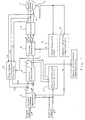
- FIG. 1 is a block diagram of a motor apparatus for explaining an adjustment method of rotor position detection of a synchronous motor of Embodiment 1 according to the present invention.
- a synchronous motor apparatus includes a synchronous motor 1 having a permanent magnet field or winding field and a controller for controlling the synchronous motor 1.
- the controller includes a resolver 2, which is a rotational position detector, for detecting a rotor position of the synchronous motor 1; a phase computing unit 3 for computing a rotor position angle ⁇ from an output of the resolver 2; a current detector 4 for detecting three-phase currents Iu, Iv, and Iw of the synchronous motor 1; and a three-phase to two-phase converter 5 for converting the rotor position angle ⁇ and the three-phase currents Iu, Iv, and Iw to d-axis and q-axis currents (actual current).
- a resolver 2 is a rotational position detector, for detecting a rotor position of the synchronous motor 1
- phase computing unit 3 for computing a rotor position angle ⁇ from an output of the resolver 2
- a current detector 4 for detecting three-phase currents Iu, Iv, and Iw of the synchronous motor 1
- a three-phase to two-phase converter 5 for converting the rotor position angle ⁇
- the controller includes an angular velocity computing unit 6 for determining the rotational angular velocity ⁇ of the synchronous motor 1 from the output of the resolver 2; a current command generator 7 for generating a d-axis current command Id* and a q-axis current command Iq* from a torque command T* and a rotational angular velocity ⁇ ; a current controller 8 for determining a d-axis voltage command Vd* and a q-axis voltage command Vq* from an error ⁇ d between the d-axis current command Id* and the d-axis current Id and an error ⁇ q between the q-axis current command Iq* and the q-axis current Iq; a voltage converter 9 for determining three-phase voltage commands Vu*, Vv*, and Vw* from the d-axis voltage command Vd* and the q-axis voltage command Vq* and the rotor position angle ⁇ ; an inverter 10 for converting electric power of a
- controller of this synchronous motor is the same as the controller configuration adopting vector control in the conventional synchronous motor or a permanent magnet field synchronous motor (DC brushless motor), except the phase correction amount detector 11, the operation of similar portion will be described briefly.
- the phase computing unit 3 determines the rotor position angle ⁇ of the synchronous motor 1 from the output of the resolver 2, which is the rotational position detector. Further, the angular velocity computing unit 6 determines the rotational angular velocity ⁇ by using the output of the resolver 2. This rotational angular velocity ⁇ and the torque command T* are inputted to the current command generator 7, and the d-axis current command Id* and the q-axis current command Iq* are determined so that the torque T at the rotational angular velocity ⁇ becomes a torque command value T*.
- the current detector 4 detects the three-phase currents Iu, Iv, and Iw flowing in the synchronous motor 1, and the d-axis current Id and the q-axis current Iq are determined from the rotor position angle ⁇ and the three-phase currents Iu, Iv, and Iw by the three-phase to two-phase converter 5.
- the current controller 8 determines the d-axis voltage command Vd* and the q-axis voltage command Vq* by performing proportional plus integral control (socalled PI control) by which the error ⁇ d between the d-axis current command Id* and the d-axis current Id and the error ⁇ q between the q-axis current command Iq* and the q-axis current Iq are controlled and by further performing decoupling control in which terms that interfere with each other are subtracted.
- the voltage converter 9 determines the three-phase voltage commands Vu*, Vv*, and Vw* based on these voltage commands Vd* and Vq* and the rotor position angle ⁇ .
- the inverter 10 performs current output control based on the three-phase voltage commands Vu*, Vv*, and Vw* to control the rotation velocity of the synchronous motor 1 and torque. Thus, vector control of the synchronous motor 1 is performed. Furthermore, in the case of having a field winding, a field current command If* is inputted to the field drive section to cause a predetermined current to flow in the field winding.
- Vd denotes the d-axis voltage
- Vq denotes the q-axis voltage
- R denotes a resistance value of one phase
- Id denotes the d-axis current
- Iq denotes the q-axis current
- Ld denotes a d-axis inductance
- Lq denotes a q-axis inductance
- ⁇ denotes rotational angular velocity
- ⁇ f denotes a magnetic flux in the permanent magnet or the winding field.
- the first embodiment provides an adjustment method of rotor position detection of a synchronous motor, wherein an amount of deviation between a rotational position of the synchronous motor determined from an output of a rotational position detector of the synchronous motor, on which vector control is performed, and an actual rotational position of the synchronous motor is adjusted, the method comprising: a step of making a d-axis current command and a q-axis current command zero regardless of a torque command based on a phase correction command for commanding adjustment for a rotational position deviation; a step of converting from three-phase current values of the synchronous motor to d-axis and q-axis currents; a step of determining a difference between the d-axis current command and the q-axis current command and the d-axis and q-axis currents; a step of determining a d-axis voltage command and a q-axis voltage command based on the difference; a step of estimating the amount of deviation based on the
- the d-axis voltage Vd and the q-axis voltage command are not required to use voltage detecting means, but the output Vd* and Vq* of the current controller 8 can be used. That is, the amount of deviation of the rotational position detector can be detected and estimated simply by using means for making the d-axis current command and the q-axis current command zero and using the already determined output Vd* and Vq* of the current controller 8 in the conventional synchronous motor apparatus, on which the vector control is performed. Further, since the amount of deviation is detected while rotating, an average value of the amount of deviation can be detected and detection accuracy of the amount of deviation is improved.
- the adjustment is performed by mechanically shifting the position of the rotational position detector in the rotational direction based on the estimated amount of deviation; after that, if necessary, the step of measuring the amount of deviation is implemented again and the adjustment is completed without shifting to mechanical adjustment of the rotational position detector when the obtained amount of deviation is smaller than a predetermined value. Further, if the obtained amount of deviation is larger than the predetermined value, the step of measuring the amount of deviation is implemented again, and mechanical adjustment of the rotational position detector may be performed again, thereby performing adjustment more certainly and improving the adjustment accuracy.
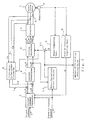
- Fig. 2 is a block diagram for explaining an adjustment method of rotor position detection of a synchronous motor of Embodiment 2 according to the present invention.
- a phase correction amount detector 11 inputs a d-axis voltage command Vd* to determine an amount of offset ⁇ concerning a rotor position angle ⁇ and outputs it to an adder 32 and also outputs it as an amount of correction detected value.
- the adder 32 adds the amount of offset ⁇ to the rotor position angle ⁇ of a phase computing unit 3.
- the phase correction command for commanding adjustment for a rotational position deviation makes the d-axis current command and the q-axis current command zero regardless of the torque command and determines a difference between these d-axis current command and q-axis current command and the d- axis and q-axis currents; then, the current controller 8 determines the d-axis voltage command and the q-axis voltage command based on the above-mentioned difference.
- Vd* which is the output of the current controller 8
- the amount of offset ⁇ is taken as + ⁇ when Vd* is positive, and is taken as - ⁇ when Vd* is negative.
- the amount of offset ⁇ is determined from an arithmetic progression (1°, 2°, ..., n°) of the angle in order and is outputted to the adder 32. In this way, ⁇ is varied until Vd* becomes zero.
- a value which subtracts half of the difference from the amount of offset ⁇ when Vd* comes close to zero and the sign of Vd* is reversed is outputted as an amount of offset ⁇ .
- ⁇ - 0.5° is set as the amount of offset. In this way, Vd* converges to zero.
- the amount of offset ⁇ determined at this time is outputted as an amount of correction detected value.
- the offset amount ⁇ is set as an amount of deviation and based on this amount of deviation, and the position of the resolver (rotational position detector) is mechanically shifted in the rotational direction to adjust it.
- the second embodiment provides an adjustment method of rotor position detection of a synchronous motor, wherein an amount of deviation between a rotational position of the synchronous motor determined from an output of a rotational position detector of the synchronous motor, on which vector control is performed, and an actual rotational position of the synchronous motor is adjusted, the method comprising: a step of making a d-axis current command and a q-axis current command zero regardless of a torque command based on a phase correction command for commanding adjustment for a rotational position deviation; a step of converting from three-phase current values of the synchronous motor to d-axis and q-axis currents; a step of determining a difference between the d-axis current command and the q-axis current command and the d-axis and q-axis currents; a step of determining a d-axis voltage command and a q-axis voltage command based on the difference; a step of estimating the amount of deviation by determining the amount
- the d-axis voltage Vd is not required to use voltage detecting means, but the output Vd* of the current controller 8 can be used. That is, the amount of deviation of the rotational position detector can be detected and estimated simply by using means for making the d-axis current command and the q-axis current command zero and using the already determined output Vd* of the current controller 8 in the conventional synchronous motor apparatus, on which the vector control is performed. Further, since the amount of deviation is detected while rotating, an average value of the amount of deviation can be detected and detection accuracy of the amount of deviation is improved.
- the adjustment is performed by mechanically shifting the position of the rotational position detector in the rotational direction based on the estimated amount of deviation; after that, if necessary, the step of measuring the amount of deviation is implemented again and the adjustment is completed without shifting to mechanical adjustment of the rotational position detector when the obtained amount of deviation is smaller than a predetermined value. Further, if the obtained amount of deviation is larger than the predetermined value, the step of measuring the amount of deviation is implemented again, and mechanical adjustment of the rotational position detector may be performed again, thereby performing adjustment more certainly and improving the adjustment accuracy.
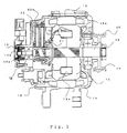
- Fig. 3 is a longitudinal sectional view showing a synchronous motor of Embodiment 3 and Fig. 4 is a front view thereof.
- a synchronous motor is composed of a rotor 12 wound by a field winding 12a, a stator 13 wound by three-phase stator windings 13a, a front bracket 14 and a rear bracket 15 holding the rotor 12 and the stator 13, a rotational position detector 16 for detecting a rotational state of the rotor 12, and the like.
- the rotor 12 is of a claw pole type.
- the rotor 12 includes a rotational shaft 19 rotatably supported by the front bracket 14 and the rear bracket 15 via bearings 17 and 18 on both sides.
- One end portion of the rotational shaft 19 protrudes from the front bracket 14 and a pulley 20 is fixed on its end portion.
- two slip rings 21 are assembled on the other end portion of the rotational shaft 19.
- the rotational position detector 16 disposed outside the rear bracket 15 is coaxially arranged with the rotational shaft 19 on the other side of the rotational shaft 19 to detect the rotational shaft 19, i.e., a magnetic pole position of the rotor 12.
- a brush 22 being in sliding contact with the slip ring 21 is held by a brush holder 22a.
- the phase correction amount detector 11 detects and estimates the amount of deviation as an amount of correction detected value.
- the rotational force of an external load device is transmitted to a belt, coupling, or the like (not shown in the figure) to make the pulley 20, the rotational shaft 19, and the rotor 12 rotate at a constant rotational velocity and the phase correction amount detector 11 detects and estimates the amount of deviation.
- the rotor 12 After that, the rotation is stopped, the rotor 12 is fixed from outside, and the amount of deviation detected and estimated according to either of the above-mentioned embodiments is adjusted by rotating a sensor stator 16a or a sensor rotor 16b in the rotational direction.
- An adjustment method of the sensor stator 16a can be easily performed by adjusting the sensor stator 16a with a jig such as a pin inserted into a hole 16c provided at the sensor stator 16a. Further, the adjustment may be performed by grasping a mounting ear 16d.
- the adjustment When adjustment is performed by turning the sensor rotor, the adjustment can be performed 360 degrees, and thus the sensor stator of the rotational position detector can be mounted at any position, thereby simplifying the assembly.
- mechanical adjustment for adjusting the amount of deviation of the rotational position detector is performed while the synchronous motor is stopped, whereby adjustment work can be done safely, mounting can be simplified, and mounting accuracy can be improved.
- the sensor stator 16a or the sensor rotor 16b of the rotational position detector 16 may be turned until the output of the rotational position detector 16 becomes a value before correction plus the amount of deviation.
- Embodiment 3 rotation is stopped when adjusting the amount of deviation; but, in Embodiment 5, the sensor stator 16a or the sensor rotor 16b may be adjusted so that the amount of deviation becomes zero while monitoring the amount of deviation while turning.
- a step for detecting the amount of deviation and a mechanical adjustment step of the rotational position detector for adjusting the amount of deviation are performed in parallel, thereby allowing the adjustment time to be shortened.
- the rotor 12 is rotated by an external load device, but, in Embodiment 6, a stator winding 13a is excited by a constant frequency with nothing connected to the rotor 12. Since there is no load, the rotor 12 rotates. After that, a d-axis current command Id* and a q-axis current command Iq* are made zero, and a measuring step of outputs Vd* and Vq* of the current controller 8 is entered. Adjustment is performed by measuring while rotating for a while because of inertia. In this case, a device for driving a synchronous motor from outside is not required, whereby equipment is low cost; and there is no vibration of equipment, thereby improving the detection accuracy.
- the present invention is suitable for application to an adjustment method of rotor position detection of a generator motor for use in an internal combustion engine.
Landscapes
- Engineering & Computer Science (AREA)
- Power Engineering (AREA)
- Control Of Ac Motors In General (AREA)
- Control Of Motors That Do Not Use Commutators (AREA)
Applications Claiming Priority (2)
| Application Number | Priority Date | Filing Date | Title |
|---|---|---|---|
| JP2004024152A JP4606033B2 (ja) | 2004-01-30 | 2004-01-30 | 同期モータの回転子位置検出調整方法 |
| PCT/JP2005/001123 WO2005074117A1 (ja) | 2004-01-30 | 2005-01-27 | 同期モータの回転子位置検出調整方法 |
Publications (3)
| Publication Number | Publication Date |
|---|---|
| EP1710902A1 true EP1710902A1 (de) | 2006-10-11 |
| EP1710902A4 EP1710902A4 (de) | 2014-01-22 |
| EP1710902B1 EP1710902B1 (de) | 2019-06-19 |
Family
ID=34823912
Family Applications (1)
| Application Number | Title | Priority Date | Filing Date |
|---|---|---|---|
| EP05709397.3A Expired - Lifetime EP1710902B1 (de) | 2004-01-30 | 2005-01-27 | Verfahren zur erkennung/einstellung der synchronmotor-rotorposition |
Country Status (4)
| Country | Link |
|---|---|
| US (1) | US7388346B2 (de) |
| EP (1) | EP1710902B1 (de) |
| JP (1) | JP4606033B2 (de) |
| WO (1) | WO2005074117A1 (de) |
Cited By (1)
| Publication number | Priority date | Publication date | Assignee | Title |
|---|---|---|---|---|
| CN102751932A (zh) * | 2008-03-21 | 2012-10-24 | 株式会社电装 | 用于改善旋转机械控制的装置 |
Families Citing this family (35)
| Publication number | Priority date | Publication date | Assignee | Title |
|---|---|---|---|---|
| JP3965934B2 (ja) * | 2001-05-09 | 2007-08-29 | 株式会社日立製作所 | 移動体の制御装置並びに移動体システム |
| WO2007148480A1 (ja) * | 2006-06-23 | 2007-12-27 | Mitsubishi Electric Corporation | ブラシレスモータ装置 |
| JP5104083B2 (ja) * | 2006-11-07 | 2012-12-19 | 日産自動車株式会社 | 電力変換装置および電力変換方法 |
| US7659688B2 (en) * | 2007-05-03 | 2010-02-09 | Gm Global Technology Operations, Inc. | Method and system for resolver alignment in electric motor system |
| US9752615B2 (en) | 2007-06-27 | 2017-09-05 | Brooks Automation, Inc. | Reduced-complexity self-bearing brushless DC motor |
| CN101790673B (zh) | 2007-06-27 | 2013-08-28 | 布鲁克斯自动化公司 | 用于自轴承电机的位置反馈 |
| US8283813B2 (en) | 2007-06-27 | 2012-10-09 | Brooks Automation, Inc. | Robot drive with magnetic spindle bearings |
| CN101855811B (zh) * | 2007-06-27 | 2013-11-20 | 布鲁克斯自动化公司 | 具有提升能力和减少的齿槽特性的电机定子 |
| KR101659931B1 (ko) | 2007-06-27 | 2016-09-26 | 브룩스 오토메이션 인코퍼레이티드 | 다차원 위치 센서 |
| US8823294B2 (en) * | 2007-06-27 | 2014-09-02 | Brooks Automation, Inc. | Commutation of an electromagnetic propulsion and guidance system |
| KR20100056468A (ko) | 2007-07-17 | 2010-05-27 | 브룩스 오토메이션 인코퍼레이티드 | 챔버 벽들에 일체화된 모터들을 갖는 기판 처리 장치 |
| KR101171659B1 (ko) * | 2008-10-29 | 2012-08-07 | 미쓰비시덴키 가부시키가이샤 | 영구자석 동기 전동기의 제어 장치 |
| JP4716143B2 (ja) * | 2008-12-19 | 2011-07-06 | 本田技研工業株式会社 | 永久磁石式回転電機の制御装置 |
| JP5169797B2 (ja) * | 2008-12-19 | 2013-03-27 | 本田技研工業株式会社 | 永久磁石式回転電機の制御装置 |
| US8278853B2 (en) * | 2009-04-16 | 2012-10-02 | Asmo Co., Ltd. | Brushless motor control apparatus, brushless motor and control method of brushless motor |
| FR2960358B1 (fr) * | 2010-05-21 | 2012-06-29 | Michelin Soc Tech | Installation et procede de mesure de decalage de l'angle d'un resolveur dans une machine electrique synchrone |
| WO2012029099A1 (ja) * | 2010-08-30 | 2012-03-08 | 三菱電機株式会社 | ヒートポンプ装置、ヒートポンプシステム及び三相インバータの制御方法 |
| US8853979B2 (en) | 2011-02-28 | 2014-10-07 | Deere & Company | Method and system for calibrating rotor position offset of an electric motor |
| JP5916342B2 (ja) | 2011-10-21 | 2016-05-11 | 三菱重工業株式会社 | モータ制御装置、モータ制御方法 |
| JP5693429B2 (ja) | 2011-10-21 | 2015-04-01 | 三菱重工業株式会社 | モータ制御装置、モータ制御方法 |
| JP5916343B2 (ja) | 2011-10-21 | 2016-05-11 | 三菱重工業株式会社 | モータ制御装置、モータ制御方法 |
| JP5838904B2 (ja) * | 2012-04-27 | 2016-01-06 | トヨタ自動車株式会社 | 車両の制御装置 |
| US9766052B2 (en) | 2013-04-22 | 2017-09-19 | Ford Global Technologies, Llc | System and method for determining rotor position offset of an electric machine |
| CN105048901B (zh) * | 2015-08-27 | 2017-11-07 | 无锡雷利电子控制技术有限公司 | 无刷电机的基于转子位置检测的自矫正启动方法 |
| KR101755922B1 (ko) * | 2015-12-09 | 2017-07-10 | 현대자동차주식회사 | 레졸버 옵셋 측정 방법 |
| JP2017175711A (ja) * | 2016-03-22 | 2017-09-28 | トヨタ自動車株式会社 | 自動車 |
| US12326725B2 (en) * | 2017-02-27 | 2025-06-10 | Northwestern University | Sensing and communication system for rotorcraft |
| JP6805035B2 (ja) * | 2017-03-14 | 2020-12-23 | 株式会社東芝 | 集積回路 |
| US11255703B2 (en) * | 2018-01-11 | 2022-02-22 | Mitsubishi Electric Corporation | Rotation angle detection device having increased accuracy |
| DE112018007527T5 (de) * | 2018-04-27 | 2021-01-14 | Mitsubishi Electric Corporation | Elektromotor-Steuervorrichtung |
| DE102018124105A1 (de) * | 2018-09-28 | 2020-04-02 | Valeo Siemens Eautomotive Germany Gmbh | Verfahren zur Ermittlung eines eine Winkeldifferenz zwischen einer angenommenen und einer tatsächlichen Lage einer d-Achse beschreibenden Korrekturwerts, Steuerungseinrichtung und Wechselrichter |
| DE102018218529A1 (de) * | 2018-10-30 | 2020-04-30 | Zf Friedrichshafen Ag | Gehäusedeckel für eine elektrische Maschine, elektrische Maschine und Montageverfahren |
| US11444562B2 (en) * | 2019-03-27 | 2022-09-13 | Eaton Intelligent Power Limited | Determining an initial position of a rotor of a permanent magnet synchronous machine |
| CN112564572B (zh) * | 2020-11-20 | 2022-05-03 | 江苏科技大学 | 基于电流偏置的永磁同步电机转子位置检测系统及方法 |
| WO2024127325A1 (en) * | 2022-12-15 | 2024-06-20 | H55 Sa | Motor controller, control system, and a method for operating the control system |
Family Cites Families (15)
| Publication number | Priority date | Publication date | Assignee | Title |
|---|---|---|---|---|
| JPH06165561A (ja) | 1992-11-26 | 1994-06-10 | Toshiba Corp | 同期電動機の制御装置 |
| JPH1094299A (ja) * | 1996-09-18 | 1998-04-10 | Meidensha Corp | 永久磁石式電動機の位置合せ方法 |
| JP2000166278A (ja) * | 1998-11-27 | 2000-06-16 | Okuma Corp | 同期電動機の制御装置 |
| JP2001204190A (ja) * | 2000-01-17 | 2001-07-27 | Yaskawa Electric Corp | 初期磁極位置推定装置その誤差調整方法 |
| JP3860949B2 (ja) * | 2000-04-19 | 2006-12-20 | 株式会社日立ビルシステム | エレベータ用永久磁石同期電動機の調整方法およびその装置 |
| JP2002325493A (ja) * | 2001-04-27 | 2002-11-08 | Hitachi Ltd | モータ制御装置 |
| JP3965934B2 (ja) * | 2001-05-09 | 2007-08-29 | 株式会社日立製作所 | 移動体の制御装置並びに移動体システム |
| JP3816353B2 (ja) * | 2001-05-25 | 2006-08-30 | 三菱電機株式会社 | 電動パワーステアリング装置用モータ |
| JP3818086B2 (ja) * | 2001-06-01 | 2006-09-06 | 株式会社日立製作所 | 同期モータの駆動装置 |
| JP2003032989A (ja) * | 2001-07-09 | 2003-01-31 | Asmo Co Ltd | ブラシレスモータのレゾルバ固定構造 |
| JP2003088081A (ja) * | 2001-09-06 | 2003-03-20 | Sankyo Seiki Mfg Co Ltd | インナーロータ型モータ |
| JP3644922B2 (ja) * | 2001-12-06 | 2005-05-11 | 本田技研工業株式会社 | 電動パワーステアリング装置 |
| JP3783667B2 (ja) * | 2002-08-06 | 2006-06-07 | 三菱電機株式会社 | 回転電機およびその回転位置センサーの位置決め方法および位置決め装置 |
| JP3688673B2 (ja) * | 2002-10-01 | 2005-08-31 | 本田技研工業株式会社 | 永久磁石式回転電機の制御装置 |
| JP3789895B2 (ja) | 2003-02-28 | 2006-06-28 | 三菱電機株式会社 | 巻線界磁型同期モータの制御装置および巻線界磁型同期モータの回転位置ずれ補正方法 |
-
2004
- 2004-01-30 JP JP2004024152A patent/JP4606033B2/ja not_active Expired - Fee Related
-
2005
- 2005-01-27 EP EP05709397.3A patent/EP1710902B1/de not_active Expired - Lifetime
- 2005-01-27 US US10/543,212 patent/US7388346B2/en not_active Expired - Lifetime
- 2005-01-27 WO PCT/JP2005/001123 patent/WO2005074117A1/ja not_active Ceased
Cited By (1)
| Publication number | Priority date | Publication date | Assignee | Title |
|---|---|---|---|---|
| CN102751932A (zh) * | 2008-03-21 | 2012-10-24 | 株式会社电装 | 用于改善旋转机械控制的装置 |
Also Published As
| Publication number | Publication date |
|---|---|
| US20060113949A1 (en) | 2006-06-01 |
| JP4606033B2 (ja) | 2011-01-05 |
| WO2005074117A1 (ja) | 2005-08-11 |
| JP2005218257A (ja) | 2005-08-11 |
| EP1710902B1 (de) | 2019-06-19 |
| US7388346B2 (en) | 2008-06-17 |
| EP1710902A4 (de) | 2014-01-22 |
Similar Documents
| Publication | Publication Date | Title |
|---|---|---|
| US7388346B2 (en) | Adjustment method of rotor position detection of synchronous motor | |
| EP1107448B1 (de) | Motorsteuerungsvorrichtung | |
| JP3789895B2 (ja) | 巻線界磁型同期モータの制御装置および巻線界磁型同期モータの回転位置ずれ補正方法 | |
| US20070222404A1 (en) | Controller for motor | |
| US7548038B2 (en) | Controller for motor | |
| JP4909797B2 (ja) | モータ制御装置 | |
| US8330403B2 (en) | Method for determining the position of the flux vector of a motor | |
| US8766571B2 (en) | Method and apparatus for controlling an electrical machine | |
| US6515446B1 (en) | Motor control apparatus and control method | |
| US7583048B2 (en) | Controller for motor | |
| US7538510B2 (en) | Controller for motor | |
| US6184647B1 (en) | Method of estimating initial pole position of permanent magnet brushless motor | |
| US20030222612A1 (en) | Motor abnormality detection apparatus and electric power steering control system | |
| US20030011340A1 (en) | Motor apparatus and control method therefor | |
| US20030128009A1 (en) | Motor control apparatus and method | |
| JP3661864B2 (ja) | ステッピングモータの駆動装置 | |
| EP2800269B1 (de) | Permanentmagnetmotorsteuerung | |
| JP2004032907A (ja) | 永久磁石式同期モータの制御装置 | |
| JP4120420B2 (ja) | モータ制御装置 | |
| JP3797508B2 (ja) | 永久磁石型同期電動機のセンサレス速度制御方法及びその脱調検出方法 | |
| US20060138992A1 (en) | Motor controller and out of control detecting method | |
| JP5641774B2 (ja) | ステッピングモータの回転子の位置及び速度を推定する方法及び装置 | |
| JP3692085B2 (ja) | モータ制御方法及び装置 | |
| JP2004072902A (ja) | Ac同期モータの磁極位置調整装置 | |
| JPH10262398A (ja) | モータの制御装置並びにその位置補正方法 |
Legal Events
| Date | Code | Title | Description |
|---|---|---|---|
| PUAI | Public reference made under article 153(3) epc to a published international application that has entered the european phase |
Free format text: ORIGINAL CODE: 0009012 |
|
| 17P | Request for examination filed |
Effective date: 20050726 |
|
| AK | Designated contracting states |
Kind code of ref document: A1 Designated state(s): DE FR |
|
| RAP1 | Party data changed (applicant data changed or rights of an application transferred) |
Owner name: MITSUBISHI DENKI KABUSHIKI KAISHA |
|
| RIN1 | Information on inventor provided before grant (corrected) |
Inventor name: UTSUMI, YOSHINOBU Inventor name: ASAO, YOSHIHITO Inventor name: NISHIMURA, SHINJI |
|
| DAX | Request for extension of the european patent (deleted) | ||
| RBV | Designated contracting states (corrected) |
Designated state(s): DE FR |
|
| A4 | Supplementary search report drawn up and despatched |
Effective date: 20140102 |
|
| RIC1 | Information provided on ipc code assigned before grant |
Ipc: H02P 21/06 20060101ALI20131217BHEP Ipc: H02K 19/00 20060101ALI20131217BHEP Ipc: H02P 5/00 20060101AFI20131217BHEP |
|
| 17Q | First examination report despatched |
Effective date: 20150115 |
|
| GRAP | Despatch of communication of intention to grant a patent |
Free format text: ORIGINAL CODE: EPIDOSNIGR1 |
|
| INTG | Intention to grant announced |
Effective date: 20190221 |
|
| RIN1 | Information on inventor provided before grant (corrected) |
Inventor name: ASAO, YOSHIHITO Inventor name: NISHIMURA, SHINJI Inventor name: UTSUMI, YOSHINOBU |
|
| GRAS | Grant fee paid |
Free format text: ORIGINAL CODE: EPIDOSNIGR3 |
|
| GRAA | (expected) grant |
Free format text: ORIGINAL CODE: 0009210 |
|
| AK | Designated contracting states |
Kind code of ref document: B1 Designated state(s): DE FR |
|
| REG | Reference to a national code |
Ref country code: DE Ref legal event code: R096 Ref document number: 602005055933 Country of ref document: DE |
|
| REG | Reference to a national code |
Ref country code: DE Ref legal event code: R097 Ref document number: 602005055933 Country of ref document: DE |
|
| PLBE | No opposition filed within time limit |
Free format text: ORIGINAL CODE: 0009261 |
|
| STAA | Information on the status of an ep patent application or granted ep patent |
Free format text: STATUS: NO OPPOSITION FILED WITHIN TIME LIMIT |
|
| 26N | No opposition filed |
Effective date: 20200603 |
|
| PGFP | Annual fee paid to national office [announced via postgrant information from national office to epo] |
Ref country code: FR Payment date: 20211217 Year of fee payment: 18 |
|
| PGFP | Annual fee paid to national office [announced via postgrant information from national office to epo] |
Ref country code: DE Payment date: 20211130 Year of fee payment: 18 |
|
| REG | Reference to a national code |
Ref country code: DE Ref legal event code: R119 Ref document number: 602005055933 Country of ref document: DE |
|
| PG25 | Lapsed in a contracting state [announced via postgrant information from national office to epo] |
Ref country code: DE Free format text: LAPSE BECAUSE OF NON-PAYMENT OF DUE FEES Effective date: 20230801 |
|
| PG25 | Lapsed in a contracting state [announced via postgrant information from national office to epo] |
Ref country code: FR Free format text: LAPSE BECAUSE OF NON-PAYMENT OF DUE FEES Effective date: 20230131 |