EP1710629A2 - Lithografischer Apparat mit zwei Trägerplatten und Verfahren zur Herstellung einer Vorrichtung - Google Patents
Lithografischer Apparat mit zwei Trägerplatten und Verfahren zur Herstellung einer Vorrichtung Download PDFInfo
- Publication number
- EP1710629A2 EP1710629A2 EP06075836A EP06075836A EP1710629A2 EP 1710629 A2 EP1710629 A2 EP 1710629A2 EP 06075836 A EP06075836 A EP 06075836A EP 06075836 A EP06075836 A EP 06075836A EP 1710629 A2 EP1710629 A2 EP 1710629A2
- Authority
- EP
- European Patent Office
- Prior art keywords
- stages
- substrate
- constructed
- lithographic apparatus
- stage
- Prior art date
- Legal status (The legal status is an assumption and is not a legal conclusion. Google has not performed a legal analysis and makes no representation as to the accuracy of the status listed.)
- Granted
Links
Images


Classifications
-
- G—PHYSICS
- G03—PHOTOGRAPHY; CINEMATOGRAPHY; ANALOGOUS TECHNIQUES USING WAVES OTHER THAN OPTICAL WAVES; ELECTROGRAPHY; HOLOGRAPHY
- G03F—PHOTOMECHANICAL PRODUCTION OF TEXTURED OR PATTERNED SURFACES, e.g. FOR PRINTING, FOR PROCESSING OF SEMICONDUCTOR DEVICES; MATERIALS THEREFOR; ORIGINALS THEREFOR; APPARATUS SPECIALLY ADAPTED THEREFOR
- G03F7/00—Photomechanical, e.g. photolithographic, production of textured or patterned surfaces, e.g. printing surfaces; Materials therefor, e.g. comprising photoresists; Apparatus specially adapted therefor
- G03F7/70—Microphotolithographic exposure; Apparatus therefor
- G03F7/70691—Handling of masks or workpieces
- G03F7/70733—Handling masks and workpieces, e.g. exchange of workpiece or mask, transport of workpiece or mask
-
- G—PHYSICS
- G03—PHOTOGRAPHY; CINEMATOGRAPHY; ANALOGOUS TECHNIQUES USING WAVES OTHER THAN OPTICAL WAVES; ELECTROGRAPHY; HOLOGRAPHY
- G03F—PHOTOMECHANICAL PRODUCTION OF TEXTURED OR PATTERNED SURFACES, e.g. FOR PRINTING, FOR PROCESSING OF SEMICONDUCTOR DEVICES; MATERIALS THEREFOR; ORIGINALS THEREFOR; APPARATUS SPECIALLY ADAPTED THEREFOR
- G03F7/00—Photomechanical, e.g. photolithographic, production of textured or patterned surfaces, e.g. printing surfaces; Materials therefor, e.g. comprising photoresists; Apparatus specially adapted therefor
- G03F7/20—Exposure; Apparatus therefor
- G03F7/2041—Exposure; Apparatus therefor in the presence of a fluid, e.g. immersion; using fluid cooling means
-
- G—PHYSICS
- G03—PHOTOGRAPHY; CINEMATOGRAPHY; ANALOGOUS TECHNIQUES USING WAVES OTHER THAN OPTICAL WAVES; ELECTROGRAPHY; HOLOGRAPHY
- G03F—PHOTOMECHANICAL PRODUCTION OF TEXTURED OR PATTERNED SURFACES, e.g. FOR PRINTING, FOR PROCESSING OF SEMICONDUCTOR DEVICES; MATERIALS THEREFOR; ORIGINALS THEREFOR; APPARATUS SPECIALLY ADAPTED THEREFOR
- G03F7/00—Photomechanical, e.g. photolithographic, production of textured or patterned surfaces, e.g. printing surfaces; Materials therefor, e.g. comprising photoresists; Apparatus specially adapted therefor
- G03F7/70—Microphotolithographic exposure; Apparatus therefor
- G03F7/70216—Mask projection systems
- G03F7/70341—Details of immersion lithography aspects, e.g. exposure media or control of immersion liquid supply
-
- G—PHYSICS
- G03—PHOTOGRAPHY; CINEMATOGRAPHY; ANALOGOUS TECHNIQUES USING WAVES OTHER THAN OPTICAL WAVES; ELECTROGRAPHY; HOLOGRAPHY
- G03F—PHOTOMECHANICAL PRODUCTION OF TEXTURED OR PATTERNED SURFACES, e.g. FOR PRINTING, FOR PROCESSING OF SEMICONDUCTOR DEVICES; MATERIALS THEREFOR; ORIGINALS THEREFOR; APPARATUS SPECIALLY ADAPTED THEREFOR
- G03F7/00—Photomechanical, e.g. photolithographic, production of textured or patterned surfaces, e.g. printing surfaces; Materials therefor, e.g. comprising photoresists; Apparatus specially adapted therefor
- G03F7/70—Microphotolithographic exposure; Apparatus therefor
- G03F7/70691—Handling of masks or workpieces
- G03F7/70716—Stages
- G03F7/70725—Stages control
Definitions
- the present invention relates to a multi stage lithographic apparatus and a method for manufacturing a device with the multi stage lithographic apparatus.
- a lithographic apparatus is a machine that applies a desired pattern onto a substrate, usually onto a target portion of the substrate.
- a lithographic apparatus can be used, for example, in the manufacture of integrated circuits (ICs).
- a patterning device which is alternatively referred to as a mask or a reticle, may be used to generate a circuit pattern to be formed on an individual layer of the IC.
- This pattern can be transferred onto a target portion (e.g. comprising part of, one, or several dies) on a substrate (e.g. a silicon wafer). Transfer of the pattern is typically via imaging onto a layer of radiation-sensitive material (resist) provided on the substrate.
- resist radiation-sensitive material
- a single substrate will contain a network of adjacent target portions that are successively patterned.
- lithographic apparatus include so-called steppers, in which each target portion is irradiated by exposing an entire pattern onto the target portion at one time, and so-called scanners, in which each target portion is irradiated by scanning the pattern through a radiation beam in a given direction (the "scanning"-direction) while synchronously scanning the substrate parallel or anti-parallel to this direction. It is also possible to transfer the pattern from the patterning device to the substrate by imprinting the pattern onto the substrate.
- An aspect herewith is to increase the throughput (throughput is related to the number of substrates that can be processed in a certain time by a lithographic apparatus).
- Dual Stage Lithographic apparatus generally have a larger throughput than Single stage apparatus since a substrate on a first substrate stage may be measured in a metrology station while another substrate on a second substrate stage is exposed in an exposure station on the basis of data measured previously in the metrology station.
- Another aspect is to improve the capability of lithographic apparatus to transfer patterns with smaller structures (but with a given quality) on substrates.
- an Immersion lithographic apparatus is capable of transferring patterns with smaller structures in comparison with non-immersion lithographic apparatus (see for example EP 1486827 ).
- a Dual Stage lithographic apparatus is described that is provided with one exposure station situated between two metrology stations.
- the substrates in the batch are measured alternately in the metrology stations before exposure in the exposure station.
- the stages can not pass each other while moving between the metrology stations and the exposure station (see Figure 3).
- a disadvantage of this lithographic apparatus is that it requires two metrology stations. Therefore, there is a necessity of providing a double substrate conveying path.
- the extra metrology station and the extra conveying path yield an expensive lithographic apparatus.
- the system layout takes relatively much (floor)-space in the factories (large footprint).
- a further disadvantage is that this concept yields problems of a logistics nature.
- the lithographic apparatus is not suitable for immersion lithographic applications such that it is not capable to project relatively small structures on the substrates.
- lithographic apparatus comprising:
- the joint scan movement yields an increased throughput compared to conventional immersion lithographic apparatus wherein a separate closing disc is used for confining the liquid between the transfer from the said first situation and the said second situation.
- lithographic apparatus comprising:
- lithographic apparatus comprising:
- lithographic apparatus comprising:
- the illumination system may include various types of optical components, such as refractive, reflective, magnetic, electromagnetic, electrostatic or other types of optical components, or any combination thereof, for directing, shaping, or controlling radiation.
- optical components such as refractive, reflective, magnetic, electromagnetic, electrostatic or other types of optical components, or any combination thereof, for directing, shaping, or controlling radiation.
- the support structure supports, i.e. bears the weight of, the patterning device. It holds the patterning device in a manner that depends on the orientation of the patterning device, the design of the lithographic apparatus, and other conditions, such as for example whether or not the patterning device is held in a vacuum environment.
- the support structure can use mechanical, vacuum, electrostatic or other clamping techniques to hold the patterning device.
- the support structure may be a frame or a table, for example, which may be fixed or movable as required.
- the support structure may ensure that the patterning device is at a desired position, for example with respect to the projection system. Any use of the terms "reticle” or “mask” herein may be considered synonymous with the more general term "patterning device.”
- patterning device used herein should be broadly interpreted as referring to any device that can be used to impart a radiation beam with a pattern in its cross-section such as to create a pattern in a target portion of the substrate. It should be noted that the pattern imparted to the radiation beam may not exactly correspond to the desired pattern in the target portion of the substrate, for example if the pattern includes phase-shifting features or so called assist features. Generally, the pattern imparted to the radiation beam will correspond to a particular functional layer in a device being created in the target portion, such as an integrated circuit.
- the patterning device may be transmissive or reflective.
- Examples of patterning devices include masks, programmable mirror arrays, and programmable LCD panels.
- Masks are well known in lithography, and include mask types such as binary, alternating phase-shift, and attenuated phase-shift, as well as various hybrid mask types.
- An example of a programmable mirror array employs a matrix arrangement of small mirrors, each of which can be individually tilted so as to reflect an incoming radiation beam in different directions. The tilted mirrors impart a pattern in a radiation beam which is reflected by the mirror matrix.
- projection system used herein should be broadly interpreted as encompassing any type of projection system, including refractive, reflective, catadioptric, magnetic, electromagnetic and electrostatic optical systems, or any combination thereof, as appropriate for the exposure radiation being used, or for other factors such as the use of an immersion liquid or the use of a vacuum. Any use of the term “projection lens” herein may be considered as synonymous with the more general term “projection system”.
- the apparatus is of a transmissive type (e.g. employing a transmissive mask).
- the apparatus may be of a reflective type (e.g. employing a programmable mirror array of a type as referred to above, or employing a reflective mask).
- the lithographic apparatus may be of a type having two (dual stage) or more substrate tables (and/or two or more mask tables). In such machines the additional tables may be used in parallel, or preparatory steps may be carried out on one or more tables while one or more other tables are being used for exposure.
- the lithographic apparatus may also be of a type wherein at least a portion of the substrate may be covered by a liquid having a relatively high refractive index, e.g. water, so as to fill a space between the projection system and the substrate.
- a liquid having a relatively high refractive index e.g. water
- An immersion liquid may also be applied to other spaces in the lithographic apparatus, for example, between the mask and the projection system. Immersion techniques are well known in the art for increasing the numerical aperture of projection systems.
- immersion as used herein does not mean that a structure, such as a substrate, must be submerged in liquid, but rather only means that liquid is located between the projection system and the substrate during exposure.
- the illuminator 2 receives a radiation beam from a radiation source 20.
- the source and the lithographic apparatus may be separate entities, for example when the source is an excimer laser. In such cases, the source is not considered to form part of the lithographic apparatus and the radiation beam is passed from the source 20 to the illuminator 2 with the aid of a beam delivery system 22 comprising, for example, suitable directing mirrors and/or a beam expander. In other cases the source may be an integral part of the lithographic apparatus, for example when the source is a mercury lamp.
- the source 20 and the illuminator 2, together with the beam delivery system 22 if required, may be referred to as a radiation system.
- the illuminator 2 may comprise an adjuster 24 for adjusting the angular intensity distribution of the radiation beam. Generally, at least the outer and/or inner radial extent (commonly referred to as ⁇ -outer and ⁇ -inner, respectively) of the intensity distribution in a pupil plane of the illuminator can be adjusted.
- the illuminator 2 may comprise various other components, such as an integrator 26 and a condenser 28. The illuminator may be used to condition the radiation beam, to have a desired uniformity and intensity distribution in its cross-section.
- the radiation beam 4 is incident on the patterning device (e.g., mask 8), which is held on the support structure (e.g., mask table 6), and is patterned by the patterning device. Having traversed the mask 8, the radiation beam 4 passes through the projection system 18, which focuses the beam onto a target portion C of the substrate 14.
- the substrate table WT of a wafer stage St can be moved accurately, e.g. so as to position different target portions C in the path of the radiation beam 4.
- known measure & Control algorithms with feedback and/or feedforward loops may be used.
- the first positioner 10 and another position sensor can be used to accurately position the mask 8 with respect to the path of the radiation beam 4, e.g. after mechanical retrieval from a mask library, or during a scan.
- movement of the mask table 6 may be realized with the aid of a long-stroke module (coarse positioning) and a short-stroke module (fine positioning), which form part of the first positioner 10.
- movement of the substrate table WT may be realized using a long-stroke module and a short-stroke module, which form part of the second positioner 16.
- the mask table 6 may be connected to a short-stroke actuator only, or may be fixed.
- Mask 8 and substrate 14 may be aligned using mask alignment marks M1, M2 and substrate alignment marks P1, P2. Although the substrate alignment marks as illustrated occupy dedicated target portions, they may be located in spaces between target portions (these are known as scribe-lane alignment marks). Similarly, in situations in which more than one die is provided on the mask 8, the mask alignment marks may be located between the dies.
- FIG 1B shows a substrate stage St (also called substrate chuck) for the lithographic apparatus according to Figure 1A.
- the stage St comprises the non-stationary parts of the second positioner 16, a mirror block MB, and the substrate table WT mounted to the mirror block MB.
- the mirror block MB is provided with interferometer-mirrors which are arranged for cooperation with interferometers for measuring the position of the mirror block MB.
- the second positioner 16 is arranged for positioning the mirror block MB and the substrate table WT.
- the second positioner 16 comprises the short stroke module (which is provided with a short stroke motor ShM) and the long stroke module (which is provided with a long stroke motor LoM).
- the long stroke motor LoM comprises a stationary part LMS that can be mounted to a stationary frame or a balance mass (not shown) and a non-stationary part LMM that is displaceable relative to the stationary part.
- the short stroke motor ShM comprises a first non-stationary part SMS (that may be mounted to the non-stationary part LMM of the long stroke motor) and a second non-stationary part SMM (that may be mounted to the mirror block MB).
- mask table 6 and the first positioner 10 may have a similar structure as depicted in Figure 1B.
- a so-called dual stage (multi stage) machine may be equipped with two (or more) stages as described.
- Each stage can be provided with an object table (such as the substrate table WT).
- a preparatory step such as the measurement of a height map of the substrate disposed on one of the object tables can be performed in parallel with the exposure of the substrate disposed on another object table.
- the stages may change position from the measurement location to the exposure location (and vice versa).
- the object tables can be moved from one stage to an other.
- Figure 4 is a schematic top-view of an embodiment of a drive and stage configuration of the lithographic apparatus schematically shown in Figure 1A.
- the part is defined by a plane indicated in Figure 1A by the line LL.
- the lithographic apparatus comprises a first metrology station 32.1, a second metrology section 32.2 and an exposure station 34 which is situated between the metrology stations 32.1, 32.2.
- FIG 2 a schematic side view of a metrology station 32 is provided.
- the metrology station is supported by a base frame 36 which carries a metro frame 38.
- the base frame 36 may be placed directly on the floor in a factory.
- the base frame 36 and the metro frame 38 are dynamically isolated by isolation means 40 (the isolation means 40 may be passive isolation means such as airmounts, active isolation means such a pneumatic pistons or combinations thereof). Due to the dynamical isolation, it is prevented that vibrations or other disturbance movements in the base frame transfer into the metro frame (the disturbances will at least be reduced to a relatively large amount).
- the metro frame and elements which are connected to it are sometimes called the "silent world".
- Figure 2 also shows a (substrate) stage 42 holding a substrate 14 and a measuring system 44 comprising a height measurement sensor 46 and a position sensor 30.
- the position sensor 30 is capable of measuring the position of the stage 42 in six degrees of freedom.
- the measuring system 44 is carried by the metro frame and is therefore part of the silent world.
- the sensors 46, 30 may be used for measuring a characteristic (height map) of the substrate 14 held by the stage 42.
- the height map is used later during exposure in the exposure station 34.
- the position sensor 30 for measuring the position of the stage 42 may be an interferometer sensor 48.1 which is capable of directing interferometer measurement beams 50 towards interferometer mirrors 52 attached to the stage 42.
- the position sensor may be an encoder system 48.2 for measuring the position of the stage 42.
- combinations of interferometers and encoders, whereby the interferometer system measures different parameters than the encoder are also possible.
- the encoder system 48.2 is an encoder plate which is attached to the metro frame 38.
- the stage 42 is provided with encoder heads 54 which are capable of cooperating with the encoder plate 48.2 for measuring the position of the stage 42.
- the encoder plate is provided with a cut-away to let the height measurement sensor 46 directing a light measurement beam through the cut-away on the surface of the substrate 8 for measuring the height of the surface of the substrate.
- each corner (at or near each corner) of the upper surface of the stage 42 is provided with an encoder head 54. The position of the stage can be measured at any location under the cut-away with the encoder system 48.2.
- Figure 3 is a schematic side view of an exposure station 34.
- the exposure station 34 is supported by the base frame 36.
- the base frame carries the metro frame 38, the metro frame 38 is dynamically isolated from the base frame 36 by the isolation means 40.
- the projection system 18 is supported by the metro frame 38 via supporting members 56 (the supporting members 56 may also be dynamical isolation means).
- the metro frame 38 carries the position sensor 30 (an interferometer 48.1 and/or an encoder system 48.2, whereby it is noted that the encoder system 48.2 is provided with a cut away for the projection system 18).
- the position sensor 30 may also be carried by the projection system 18 (or, equivalently, by a frame attached to the projection system 18).
- this encoder plate may extend both in the exposure station 34 and the metrology station 32. In an advanced embodiment there is only one encoder plate which extends completely from the metrology station 32 to the exposure station 34.
- a reticle stage or mask stage 6 is located above the projection system 18.
- the position of the reticle stage and the position of the mask/reticle are measured by a measuring system 60.
- the measuring system 60 cooperates with the position sensor 30 in order to align the mask/reticle with the substrate 14 under the projection system 18.
- Aligning the mask/reticle to the substrate is usually performed according to zero point sensors and TIS-alignment techniques (see for a description EP 1510870 ). For applying the TIS-alignment it is required that the position of the substrate with respect to the base frame 36 is known within a certain accuracy (rough indication as starting point for the fine TIS measurements) such that the substrate is in the capture range of the TIS sensor.
- interferometer sensors measure relative positions (by counting fringes).
- the interferometer sensors can be "zerod" by means of a so-called zeroing-operation, which means that a reference point is defined in order to obtain absolute position measurements.
- a reference point is defined in order to obtain absolute position measurements.
- Defining such a reference point is of special interest in a multi-stage apparatus, since in such an apparatus it frequently occurs that one stage eclipses another stage yielding a loss of an already defined reference point. If this happens it may be necessary to define a new reference point (according to a new zeroing operation) has to be defined which costs time and reduces throughput.
- the application of the encoder plate may yield an absolute measurement system which reduces or even eliminates the necessary zeroing operations which is beneficial for throughput.
- the frequency of TIS-alignments itself may also be reduced or even eliminated (at least partly replaced by the encoder measurements), such that the throughput of the corresponding apparatus is further increased.
- Figure 4 schematically depicts two guides 62.1, 62.2 which extend in a first direction (the X-direction) in a horizontal plane.
- the guides 62 may be attached to the base frame 36, but it is preferred to attach the guides 62 to a machine frame which is completely separated (thus no dynamical coupling) from the said base frame 36, the metro frame 38 and the projection lens 18.
- Each guide 62 is coupled to elements 64 which can be moved along the guide 62 in the first direction (X-direction) by means of a motor of the positioning system.
- each stage 42.1, 42.2 is coupled to two elements 64.
- Each stage can be moved in the horizontal plane in the Y-direction (which is essentially perpendicular to the first direction) by motors in the elements 64.
- the motors in the guides 62 and/or in the elements 64 cooperate with balance masses in order to reduce effects of reaction forces.
- the stages 42.1, 42.2 may be supported by the base frame 36 via an air bearing which yields a dynamical isolation of the base frame 26 and the stages 42.1, 42.2. It is noted that as an alternative of the described drive configuration a planar motor configuration may be applied.
- the stages can not pass each other. Therefore, the working sequence of the lithographic apparatus which belongs to this configuration is as follows.
- a substrate 14.1 is provided on the first stage 42.1 via a first substrate convey path to the first metrology station 32.1. Then this substrate is measured (see Figure 2, measurement system 44, generation of a height map) in the metrology station 32.1 while being scanned in the horizontal plane (the stage 42.1 is moved in the horizontal plane for this).
- the position of the stages 42.1, 42.2 is, in the example of Figure 4, measured by an interferometer system 48.1.
- the stage is transferred to the exposure station 34 in order to expose the substrate 14.1 held by the stage 42.1.
- the exposure is based on the measured height map of the substrate 14.1, wherein the stage 42.1 holding the substrate is positioned by the positioning system. (It is noted that the said motors are capable of positioning the stage in six degrees of freedom, however within a limited range, under the projection system 18).
- the other stage 42.2 is in the second metrology station 32.2 and holds a substrate 14.2 which is measured.
- the substrate 14.2 has been supplied via a second substrate convey path.
- the exposed substrate 14.1 is conveyed via the first substrate convey path, and a new substrate to be measured is loaded on the stage 42.1 via the first substrate convey path.
- the substrate 14.2 held by the stage 42.2 is exposed.
- the sequence continues in this way. It is clear that the configuration requires a double substrate convey path.
- the beams of the interferometers sometimes have to bridge relatively great distances between the interferometer system and the interferometer-mirror attached to the stage (see Figure 4, interferometer beams in the X-direction). This decreases the accuracy of the measurement in this direction, since pressure variations in the air disturb the interferometer measurement beam (this effect increases with an increased distance).
- Application of the discussed encoder system 48.2 alleviates this disadvantage and may yield higher measurement accuracies.
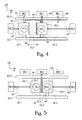
- FIG. 6 schematically depicts another dual stage concept in a top-view defined by the line LL in Figure 1.
- stages with substrates 42.1, 42.2 can be exchanged between the metrology station 32 and the exposure station 34.
- the concept is provided with two guides 62.1, 62.2 which extend in a first direction (the X-direction) in a horizontal plane.
- the guides 62 may be attached to the base frame 36, but it is preferred to attach the guides 62 to a machine frame which is completely separated (thus no dynamical coupling) from the said base frame 36, the metro frame 38 and the projection lens 18.
- Each guide 62 carries an element 64 which can be moved along the guide 62 in the first direction (X-direction) by means of a motor (part of and) controlled by the positioning system.
- the elements 64 are T-elements which are part of a so-called "T-drive".
- Each stage 42.1, 42.2 is coupled to one T-element 64, wherein the T-element 64 can move the stage to which it is coupled in the Y-direction by a motor which may be present in the element 64.
- the motor is (preferably part of and) controlled by the positioning system.
- the motors in the guides 62 and/or in the elements 64 cooperate with balance masses in order to reduce effects of reaction forces.
- the stages 42.1, 42.2 may be supported by the base frame 36 via a dynamically isolating air bearing.
- the dual stage concept according to Figure 6 allows the stages 42.1 and 42.2 to pass each other while being moved between the metrology station 32 and the exposure station 34.
- This concept based on the T-drives does not require a stage swap (in contrast to the H-drive concept described in US 5,969,441 ). Therefore a relatively high throughput can be achieved since a continuous transfer movement of the stages is possible without a stop for a swap.
- a planar motor configuration can be used.
- the lithographic apparatus is provided with a machine frame with coils and/or magnets (the first part of the planar motor) for cooperating with magnets and/or coils in the said stages 42.1, 42.2 (the respective second parts of the planar motor) such that the positioning system can move each of the said stages 42.1, 42.2 between the metrology station 32 and the exposure station 34.
- Such a planar motor can also be used to position the stages in the exposure station 34 in six degrees of freedom.
- the machine frame may be part of the base frame 36 (then the coils and/or magnets) are integrated in the base frame 36, or the machine frame is separated (dynamically isolated) from the base frame 36.
- the planar motor is under control of the positioning system.
- an immersion liquid 66 between a final optical (lens) element of the projection system 18 and a target portion of the substrate 14 ( Figure 3).
- the application of immersion fluid yields the advantage that during exposure smaller structures of patterns can be transferred from the reticle or mask to substrates 14 than in a comparable system without immersion fluid.
- the lithographic apparatus has a liquid confinement system for confining liquid between a final element of the projection system and the substrate.
- the liquid confinement system comprises a so-called immersion hood 68 (see Figure 9).
- the immersion fluid may be kept in place during illumination by the immersion hood 68.
- the immersion hood 68 may comprise a mechanical contact-seal and/or may also comprise a contact-less seal which operation is based on guiding a pressure-gas-flow towards the fluid to be confined (combinations are possible).
- the stage holding it After exposure of a substrate the stage holding it has to move away, for example towards a metrology station. Since it is desired that the immersion fluid 66 is kept in its space under the final element of the projection system 18, special measures have to be taken before the stage can be moved away from its position under the space of the immersion liquid 66. A possibility is to use a separate closing disc or a separate small closing stage (unable to hold a substrate) which closes the space at the bottom, until a stage holding a substrate to be exposed takes the place of the closing disc/closing stage.
- the said closing disc/closing stage yields extra take-over operations which cost valuable time and which appear to decrease the throughput of the lithographic apparatus significantly.
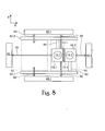
- the said joint scan movement of the stages 42.1 and 42.2 is illustrated schematically in Figure 9 (the arrows 71 indicate the direction of movement of the stages with respect to the projection system 18).
- the joint scan movement is performed such that the liquid 66 stays confined in its space under the final lens element 70.
- the stages 42.1, 42.2 confine the liquid 66.
- the immersion hood which preferably stays in an essentially fixed position with respect to the projection system 18 which confines the liquid 66.
- each immersion cross edge 72 comprises one or more essentially plane and smooth surface(s).
- the cooperating immersion cross edges of the stages define a space with a mutual distance D during the joint scan movement.
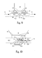
- FIG. 10 A different shape of the immersion cross edges 72.1, 72.2 is shown in Figure 10.
- the stage 42.1 shows an immersion cross edge with respectively a vertical plane A, a horizontal plane B and a vertical plane C. These planes are constructed to cooperate with respective planes D, E, F of the immersion cross edge 72.2.
- the lithographic apparatus may comprise a control system (using a feedback and/or a feedforward loop) that may be fed with position measurements (actually the term position measurement may include position, velocity, acceleration and/or jerk measurements) of the stages (the measurements may be performed by the measurement system 44) for calculating setpoint-signals for the relevant motors.
- the motors are controlled during the joint scan movement of the stages by the positioning system according to the setpoint-signals such that the mutual constant distance D between the planes of the respective immersion cross edges corresponds to a pre-determined function.
- the pre-determined function may be chosen such that the space between the immersion cross edges functions a liquid channel character (see below for further description).
- the positioning system is constructed and arranged to control the motors for moving the stages such that stage 42.1 pushes the stage 42.2 gently during the joint scan movement.
- a control system using a feedback and/or a feedforward loop
- position measurements actually the term position measurement may include position, velocity, acceleration and/or jerk measurements
- motors are controlled by the positioning system according to the setpoint-signals such that the mutual constant distance D between the planes of the respective immersion cross edges is essentially zero.
- the positioning system is constructed and arranged to control the motors for moving the stages such that during the joint scan movement the said mutual distance D is larger than zero but smaller that 1 millimeter.
- a favorable mutual distance D appears to be between 0.05 and 0.2 millimeter.
- a distance D in this distance-range is especially favorable if one of the stages is provided with a channel system 74 leading to and from an opening the immersion cross edge, wherein the channel system 74 is constructed and arranged for generating a flow of gas and/or liquid along the immersion cross edge during the joint scan movement. The generation of this flow is of importance to reduce the chance that bubbles (bubbles deteriorate the projection of patterns on the substrate) are generated in the immersion liquid 66.
- a stable and well controlled distance D results in a stable and well favorable flow thereby avoiding the generation of bubbles in the immersion liquid during the joint scan movement.
- a channel system 74 may yield (during the joint scan movement) a gas flow from under the stages 42 (see for example Figure 11 with indication G) and a liquid flow from above the stages (see for example Figure 11 with indication L). Then a mixture of gas and liquid will be drained away via the channel system 74 (see indication L/G). Flexible tubes may be connected to the (channel system 74 of the) stage for further transport of the mixture L/G.
- each stage (42.1 respectively 42.2) has a channel system (74.1 respectively 74.2), wherein each channel system leads to an opening in a plane surface of the immersion cross edge (72.1 respectively 72.2).
- the stage 42.2 is provided with a channel system 74, wherein the channel system 74 has three openings in the surface E of the immersion cross edge 72.2. Little arrows in the channel system 74 show the direction of the flow during the joint scan movement.
- Figures 10, 13, 14 show a configuration wherein the stages 42.1, 42.2 are provided with a water gutter 76.1, 76.2 under the immersion cross edges 72.1, 72.2.
- the water gutter is capable of catching liquid possible dripped along the immersion cross edge before, during and after the joint scan movement.
- Application of only one water gutter attached to only one of the stages is in principle sufficient for only catching liquid during the joint scan movement.
- the said interferometer system 48.1 uses interferometer-mirrors attached to the stages for position measuring. In the example of Figure 4 it does not make sense for the interferometer system 48.1 to have interferometer mirrors 52 on the stages at the sides of the immersion cross edges. However, for the drive and stage configuration in Figure 6, it may be advantageous to have an interferometer-mirrors 52 at the stages at the sides of the immersion cross edges (for example to have relative short distances of the interferometer beam, which generally yields relative high measurement accuracies).
- the stages are provided with an interferometer-mirror 52 at the immersion cross edge. It is noted that the chance on contamination (liquid flow) and or damage arising during the joint scan movement is greater than for the other interferometer-mirrors. Therefore it is advantageous to stagger the interferometer-mirror with respect to the immersion cross edge as indicated in Figure 12. As an alternative the interferometer-mirrors 52 are placed it in a protective niche of the stage, as indicated in Figure 13.
- FIG. 14 shows an example of a combination of the mentioned measures whereby the interferometer-mirrors are both staggered with respect to the immersion cross edge 72 and placed at a level under the water gutter 76. In this way the interferometers stay clean and undamaged which yield a reliable performance of the measurement system.
- lithographic apparatus in the manufacture of ICs
- the lithographic apparatus described herein may have other applications, such as the manufacture of integrated optical systems, guidance and detection patterns for magnetic domain memories, flat-panel displays, liquid-crystal displays (LCDs), thin-film magnetic heads, etc.
- LCDs liquid-crystal displays
- any use of the terms “wafer” or “die” herein may be considered as synonymous with the more general terms “substrate” or "target portion”, respectively.
- the substrate referred to herein may be processed, before or after exposure, in for example a track (a tool that typically applies a layer of resist to a substrate and develops the exposed resist), a metrology tool and/or an inspection tool. Where applicable, the disclosure herein may be applied to such and other substrate processing tools. Further, the substrate may be processed more than once, for example in order to create a multi-layer IC, so that the term substrate used herein may also refer to a substrate that already contains multiple processed layers.
- imprint lithography a topography in a patterning device defines the pattern created on a substrate.
- the topography of the patterning device may be pressed into a layer of resist supplied to the substrate whereupon the resist is cured by applying electromagnetic radiation, heat, pressure or a combination thereof.
- the patterning device is moved out of the resist leaving a pattern in it after the resist is cured.
- UV radiation e.g. having a wavelength of or about 365, 355, 248, 193, 157 or 126 nm
- EUV radiation e.g. having a wavelength in the range of 5-20 nm
- particle beams such as ion beams or electron beams.
- lens may refer to any one or combination of various types of optical components, including refractive, reflective, magnetic, electromagnetic and electrostatic optical components.
- the invention may take the form of a computer program containing one or more sequences of machine-readable instructions describing a method as disclosed above, or a data storage medium (e.g. semiconductor memory, magnetic or optical disk) having such a computer program stored therein.
- a data storage medium e.g. semiconductor memory, magnetic or optical disk
Landscapes
- Physics & Mathematics (AREA)
- General Physics & Mathematics (AREA)
- Exposure And Positioning Against Photoresist Photosensitive Materials (AREA)
- Exposure Of Semiconductors, Excluding Electron Or Ion Beam Exposure (AREA)
Applications Claiming Priority (2)
| Application Number | Priority Date | Filing Date | Title |
|---|---|---|---|
| US10163105A | 2005-04-08 | 2005-04-08 | |
| US11/135,655 US7161659B2 (en) | 2005-04-08 | 2005-05-24 | Dual stage lithographic apparatus and device manufacturing method |
Publications (3)
| Publication Number | Publication Date |
|---|---|
| EP1710629A2 true EP1710629A2 (de) | 2006-10-11 |
| EP1710629A3 EP1710629A3 (de) | 2007-04-11 |
| EP1710629B1 EP1710629B1 (de) | 2010-12-01 |
Family
ID=36659724
Family Applications (1)
| Application Number | Title | Priority Date | Filing Date |
|---|---|---|---|
| EP06075836A Not-in-force EP1710629B1 (de) | 2005-04-08 | 2006-04-07 | Lithografischer Apparat mit zwei Trägerplatten und Verfahren zur Herstellung einer Vorrichtung |
Country Status (5)
| Country | Link |
|---|---|
| US (1) | US7161659B2 (de) |
| EP (1) | EP1710629B1 (de) |
| KR (1) | KR100858980B1 (de) |
| DE (1) | DE602006018552D1 (de) |
| SG (1) | SG126866A1 (de) |
Cited By (7)
| Publication number | Priority date | Publication date | Assignee | Title |
|---|---|---|---|---|
| WO2008044612A1 (en) * | 2006-09-29 | 2008-04-17 | Nikon Corporation | Exposure apparatus, exposure method, and device manufacturing method |
| WO2011037276A1 (en) * | 2009-09-28 | 2011-03-31 | Nikon Corporation | Exposure apparatus and device fabricating method |
| US8115906B2 (en) | 2007-12-14 | 2012-02-14 | Nikon Corporation | Movable body system, pattern formation apparatus, exposure apparatus and measurement device, and device manufacturing method |
| CN102866587A (zh) * | 2011-07-08 | 2013-01-09 | 上海微电子装备有限公司 | 工件台 |
| WO2014063995A1 (en) * | 2012-10-24 | 2014-05-01 | Asml Netherlands B.V. | Substrate positioning system, lithographic apparatus and device manufacturing method |
| EP2189849A3 (de) * | 2008-11-21 | 2014-10-15 | ASML Netherlands B.V. | Lithographievorrichtung mit einer Wechselbrücke |
| CN105652603A (zh) * | 2007-07-18 | 2016-06-08 | 株式会社尼康 | 曝光装置、曝光方法、及元件制造方法 |
Families Citing this family (77)
| Publication number | Priority date | Publication date | Assignee | Title |
|---|---|---|---|---|
| KR101498405B1 (ko) | 2003-04-11 | 2015-03-04 | 가부시키가이샤 니콘 | 액침 리소그래피 머신에서 웨이퍼 교환동안 투영 렌즈 아래의 갭에서 액침 액체를 유지하는 장치 및 방법 |
| KR101148811B1 (ko) | 2003-06-19 | 2012-05-24 | 가부시키가이샤 니콘 | 노광 장치 및 디바이스 제조방법 |
| US7589822B2 (en) | 2004-02-02 | 2009-09-15 | Nikon Corporation | Stage drive method and stage unit, exposure apparatus, and device manufacturing method |
| EP3306647A1 (de) * | 2004-10-15 | 2018-04-11 | Nikon Corporation | Belichtungsvorrichtung und vorrichtungsherstellungsverfahren |
| JP4848956B2 (ja) | 2004-11-01 | 2011-12-28 | 株式会社ニコン | 露光装置、露光方法、及びデバイス製造方法 |
| US7515281B2 (en) * | 2005-04-08 | 2009-04-07 | Asml Netherlands B.V. | Lithographic apparatus and device manufacturing method |
| CN100555568C (zh) * | 2005-04-28 | 2009-10-28 | 株式会社尼康 | 曝光方法及曝光装置、以及元件制造方法 |
| EP1918983A4 (de) * | 2005-08-05 | 2010-03-31 | Nikon Corp | Bühnenvorrichtung und belichtungsvorrichtung |
| US8780326B2 (en) * | 2005-09-09 | 2014-07-15 | Nikon Corporation | Exposure apparatus, exposure method, and device manufacturing method |
| US7839485B2 (en) * | 2006-01-19 | 2010-11-23 | Nikon Corporation | Movable body drive method, movable body drive system, pattern formation method, pattern forming apparatus, exposure method, exposure apparatus, and device manufacturing method |
| WO2007097379A1 (ja) | 2006-02-21 | 2007-08-30 | Nikon Corporation | パターン形成装置、マーク検出装置、露光装置、パターン形成方法、露光方法及びデバイス製造方法 |
| US8027021B2 (en) | 2006-02-21 | 2011-09-27 | Nikon Corporation | Measuring apparatus and method, processing apparatus and method, pattern forming apparatus and method, exposure apparatus and method, and device manufacturing method |
| EP3293577A1 (de) | 2006-02-21 | 2018-03-14 | Nikon Corporation | Belichtungsapparat, belichtungsverfahren und verfahren zur herstellung einer vorrichtung |
| US7483120B2 (en) * | 2006-05-09 | 2009-01-27 | Asml Netherlands B.V. | Displacement measurement system, lithographic apparatus, displacement measurement method and device manufacturing method |
| CN100456138C (zh) * | 2006-06-13 | 2009-01-28 | 上海微电子装备有限公司 | 浸没式光刻机浸液流场维持系统 |
| SG182982A1 (en) | 2006-08-31 | 2012-08-30 | Nikon Corp | Movable body drive method and movable body drive system, pattern formation method and apparatus, exposure method and apparatus, and device manufacturing method |
| KR101862528B1 (ko) | 2006-08-31 | 2018-05-29 | 가부시키가이샤 니콘 | 이동체 구동 시스템 및 이동체 구동 방법, 패턴 형성 장치 및 방법, 노광 장치 및 방법, 디바이스 제조 방법, 그리고 결정 방법 |
| TWI537687B (zh) | 2006-08-31 | 2016-06-11 | 尼康股份有限公司 | Mobile body driving method and moving body driving system, pattern forming method and apparatus, exposure method and apparatus, and component manufacturing method |
| CN102749813B (zh) * | 2006-09-01 | 2014-12-03 | 株式会社尼康 | 曝光方法及装置、以及组件制造方法 |
| SG183736A1 (en) * | 2006-09-01 | 2012-09-27 | Nikon Corp | Movable body drive method and movable body drive system, pattern formation method and apparatus, exposure method and apparatus, device manufacturing method, and calibration method |
| US7872730B2 (en) * | 2006-09-15 | 2011-01-18 | Nikon Corporation | Immersion exposure apparatus and immersion exposure method, and device manufacturing method |
| WO2008038752A1 (fr) * | 2006-09-29 | 2008-04-03 | Nikon Corporation | système à unité MOBILE, DISPOSITIF DE FORMATION DE MOTIF, DISPOSITIF D'EXPOSITION, PROCÉDÉ D'EXPOSITION, ET PROCÉDÉ DE FABRICATION DE DISPOSITIF |
| US20080158531A1 (en) * | 2006-11-15 | 2008-07-03 | Nikon Corporation | Exposure apparatus, exposure method, and method for producing device |
| US7903866B2 (en) | 2007-03-29 | 2011-03-08 | Asml Netherlands B.V. | Measurement system, lithographic apparatus and method for measuring a position dependent signal of a movable object |
| JP5489068B2 (ja) * | 2007-07-24 | 2014-05-14 | 株式会社ニコン | 位置計測システム、露光装置、位置計測方法、露光方法及びデバイス製造方法、並びに工具及び計測方法 |
| US20090051895A1 (en) * | 2007-08-24 | 2009-02-26 | Nikon Corporation | Movable body drive method and movable body drive system, pattern formation method and apparatus, device manufacturing method, and processing system |
| US8237919B2 (en) * | 2007-08-24 | 2012-08-07 | Nikon Corporation | Movable body drive method and movable body drive system, pattern formation method and apparatus, exposure method and apparatus, and device manufacturing method for continuous position measurement of movable body before and after switching between sensor heads |
| TW200916696A (en) * | 2007-10-11 | 2009-04-16 | Hannspree Inc | Flat-panel display with illumination function |
| US8279399B2 (en) | 2007-10-22 | 2012-10-02 | Nikon Corporation | Exposure apparatus, exposure method, and device manufacturing method |
| US9013681B2 (en) * | 2007-11-06 | 2015-04-21 | Nikon Corporation | Movable body apparatus, pattern formation apparatus and exposure apparatus, and device manufacturing method |
| WO2009060585A1 (ja) * | 2007-11-07 | 2009-05-14 | Nikon Corporation | 露光装置及び露光方法、並びにデバイス製造方法 |
| US9256140B2 (en) * | 2007-11-07 | 2016-02-09 | Nikon Corporation | Movable body apparatus, pattern formation apparatus and exposure apparatus, and device manufacturing method with measurement device to measure movable body in Z direction |
| US8665455B2 (en) * | 2007-11-08 | 2014-03-04 | Nikon Corporation | Movable body apparatus, pattern formation apparatus and exposure apparatus, and device manufacturing method |
| US8422015B2 (en) * | 2007-11-09 | 2013-04-16 | Nikon Corporation | Movable body apparatus, pattern formation apparatus and exposure apparatus, and device manufacturing method |
| US8711327B2 (en) * | 2007-12-14 | 2014-04-29 | Nikon Corporation | Exposure apparatus, exposure method, and device manufacturing method |
| US8237916B2 (en) | 2007-12-28 | 2012-08-07 | Nikon Corporation | Movable body drive system, pattern formation apparatus, exposure apparatus and exposure method, and device manufacturing method |
| US8792079B2 (en) * | 2007-12-28 | 2014-07-29 | Nikon Corporation | Exposure apparatus, exposure method, and device manufacturing method having encoders to measure displacement between optical member and measurement mount and between measurement mount and movable body |
| KR101477833B1 (ko) * | 2007-12-28 | 2014-12-30 | 가부시키가이샤 니콘 | 노광 장치, 이동체 구동 시스템, 패턴 형성 장치 및 노광 방법, 그리고 디바이스 제조 방법 |
| US8269945B2 (en) * | 2007-12-28 | 2012-09-18 | Nikon Corporation | Movable body drive method and apparatus, exposure method and apparatus, pattern formation method and apparatus, and device manufacturing method |
| JP2009218564A (ja) * | 2008-02-12 | 2009-09-24 | Canon Inc | 露光装置及びデバイス製造方法 |
| KR20110018332A (ko) | 2008-04-30 | 2011-02-23 | 가부시키가이샤 니콘 | 스테이지 장치, 패턴 형성 장치, 노광 장치, 스테이지 구동 방법, 노광 방법, 그리고 디바이스 제조 방법 |
| US8786829B2 (en) * | 2008-05-13 | 2014-07-22 | Nikon Corporation | Exposure apparatus, exposure method, and device manufacturing method |
| US8817236B2 (en) | 2008-05-13 | 2014-08-26 | Nikon Corporation | Movable body system, movable body drive method, pattern formation apparatus, pattern formation method, exposure apparatus, exposure method, and device manufacturing method |
| US8228482B2 (en) * | 2008-05-13 | 2012-07-24 | Nikon Corporation | Exposure apparatus, exposure method, and device manufacturing method |
| US9176393B2 (en) * | 2008-05-28 | 2015-11-03 | Asml Netherlands B.V. | Lithographic apparatus and a method of operating the apparatus |
| US8325325B2 (en) * | 2008-09-22 | 2012-12-04 | Nikon Corporation | Movable body apparatus, movable body drive method, exposure apparatus, exposure method, and device manufacturing method |
| US8994923B2 (en) * | 2008-09-22 | 2015-03-31 | Nikon Corporation | Movable body apparatus, exposure apparatus, exposure method, and device manufacturing method |
| JP2010140958A (ja) * | 2008-12-09 | 2010-06-24 | Canon Inc | 露光装置及びデバイス製造方法 |
| US8902402B2 (en) * | 2008-12-19 | 2014-12-02 | Nikon Corporation | Movable body apparatus, exposure apparatus, exposure method, and device manufacturing method |
| US8773635B2 (en) * | 2008-12-19 | 2014-07-08 | Nikon Corporation | Exposure apparatus, exposure method, and device manufacturing method |
| US8760629B2 (en) | 2008-12-19 | 2014-06-24 | Nikon Corporation | Exposure apparatus including positional measurement system of movable body, exposure method of exposing object including measuring positional information of movable body, and device manufacturing method that includes exposure method of exposing object, including measuring positional information of movable body |
| US8599359B2 (en) | 2008-12-19 | 2013-12-03 | Nikon Corporation | Exposure apparatus, exposure method, device manufacturing method, and carrier method |
| US8472008B2 (en) * | 2009-06-19 | 2013-06-25 | Nikon Corporation | Movable body apparatus, exposure apparatus and device manufacturing method |
| NL2004735A (en) * | 2009-07-06 | 2011-01-10 | Asml Netherlands Bv | Imprint lithography apparatus and method. |
| US8493547B2 (en) | 2009-08-25 | 2013-07-23 | Nikon Corporation | Exposure apparatus, exposure method, and device manufacturing method |
| US8514395B2 (en) | 2009-08-25 | 2013-08-20 | Nikon Corporation | Exposure method, exposure apparatus, and device manufacturing method |
| US8488109B2 (en) | 2009-08-25 | 2013-07-16 | Nikon Corporation | Exposure method, exposure apparatus, and device manufacturing method |
| JP2011054694A (ja) * | 2009-08-31 | 2011-03-17 | Canon Inc | 計測装置、露光装置およびデバイス製造方法 |
| NL2005126A (en) * | 2009-09-21 | 2011-03-22 | Asml Netherlands Bv | Lithographic apparatus, coverplate and device manufacturing method. |
| US20110096306A1 (en) * | 2009-09-28 | 2011-04-28 | Nikon Corporation | Stage apparatus, exposure apparatus, driving method, exposing method, and device fabricating method |
| US20110102761A1 (en) * | 2009-09-28 | 2011-05-05 | Nikon Corporation | Stage apparatus, exposure apparatus, and device fabricating method |
| US20110096312A1 (en) * | 2009-09-28 | 2011-04-28 | Nikon Corporation | Exposure apparatus and device fabricating method |
| US20110128523A1 (en) * | 2009-11-19 | 2011-06-02 | Nikon Corporation | Stage apparatus, exposure apparatus, driving method, exposing method, and device fabricating method |
| US20110123913A1 (en) * | 2009-11-19 | 2011-05-26 | Nikon Corporation | Exposure apparatus, exposing method, and device fabricating method |
| US20110164238A1 (en) * | 2009-12-02 | 2011-07-07 | Nikon Corporation | Exposure apparatus and device fabricating method |
| US8488106B2 (en) * | 2009-12-28 | 2013-07-16 | Nikon Corporation | Movable body drive method, movable body apparatus, exposure method, exposure apparatus, and device manufacturing method |
| WO2012016744A1 (en) * | 2010-08-05 | 2012-02-09 | Asml Netherlands B.V. | Imprint lithography |
| KR101212035B1 (ko) * | 2010-10-01 | 2012-12-12 | 한국영상기술(주) | 고속 부품 검사 장치 |
| US9207549B2 (en) | 2011-12-29 | 2015-12-08 | Nikon Corporation | Exposure apparatus and exposure method, and device manufacturing method with encoder of higher reliability for position measurement |
| NL2011253A (en) | 2012-08-23 | 2014-02-25 | Asml Netherlands Bv | Lithographic apparatus, device manufacturing method and displacement measurement system. |
| JP6362312B2 (ja) * | 2013-09-09 | 2018-07-25 | キヤノン株式会社 | 露光装置、それを用いたデバイスの製造方法 |
| TWM523958U (zh) * | 2014-08-01 | 2016-06-11 | 應用材料股份有限公司 | 用於執行光刻製程的處理系統 |
| WO2016136690A1 (ja) | 2015-02-23 | 2016-09-01 | 株式会社ニコン | 計測装置、リソグラフィシステム及び露光装置、並びに管理方法、重ね合わせ計測方法及びデバイス製造方法 |
| CN111948912A (zh) | 2015-02-23 | 2020-11-17 | 株式会社尼康 | 基板处理系统及基板处理方法、以及组件制造方法 |
| KR102552792B1 (ko) | 2015-02-23 | 2023-07-06 | 가부시키가이샤 니콘 | 계측 장치, 리소그래피 시스템 및 노광 장치, 그리고 디바이스 제조 방법 |
| CN113267964B (zh) | 2015-09-30 | 2023-05-23 | 株式会社尼康 | 曝光装置及曝光方法、以及平面显示器制造方法 |
| WO2023232282A1 (en) | 2022-05-31 | 2023-12-07 | Carl Zeiss Smt Gmbh | Dual beam systems and methods for decoupling the working distance of a charged particle beam device from focused ion beam geometry induced constraints |
Citations (6)
| Publication number | Priority date | Publication date | Assignee | Title |
|---|---|---|---|---|
| EP1111471A2 (de) | 1999-12-21 | 2001-06-27 | Asm Lithography B.V. | Lithographischer Projektionsapparat mit kollisionsvermeidender Positionierungsvorrichtung |
| US6341007B1 (en) | 1996-11-28 | 2002-01-22 | Nikon Corporation | Exposure apparatus and method |
| EP1220037A2 (de) | 2000-12-28 | 2002-07-03 | Nikon Corporation | Belichtungsapparat und Verfahren zur Herstellung eines Belichtungsapparates |
| US6417914B1 (en) | 1999-10-18 | 2002-07-09 | Nikon Corporation | Stage device and exposure apparatus |
| US20030076482A1 (en) | 2001-10-22 | 2003-04-24 | Fuyuhiko Inoue | Two stage method |
| EP1635382A1 (de) | 2003-06-19 | 2006-03-15 | Nikon Corporation | Belichtungseinrichtung und bauelementeherstellungsverfahren |
Family Cites Families (4)
| Publication number | Priority date | Publication date | Assignee | Title |
|---|---|---|---|---|
| EP0890136B9 (de) * | 1996-12-24 | 2003-12-10 | ASML Netherlands B.V. | In zwei richtungen ausgewogenes positioniergerät, sowie lithographisches gerät mit einem solchen positioniergerät |
| JP4362862B2 (ja) * | 2003-04-01 | 2009-11-11 | 株式会社ニコン | ステージ装置及び露光装置 |
| KR20060009356A (ko) * | 2003-05-15 | 2006-01-31 | 가부시키가이샤 니콘 | 노광 장치 및 디바이스 제조 방법 |
| EP2261742A3 (de) | 2003-06-11 | 2011-05-25 | ASML Netherlands BV | Lithographischer Apparat und Verfahren zur Herstellung einer Vorrichtung |
-
2005
- 2005-05-24 US US11/135,655 patent/US7161659B2/en not_active Ceased
-
2006
- 2006-04-07 KR KR1020060032072A patent/KR100858980B1/ko active IP Right Grant
- 2006-04-07 SG SG200602345A patent/SG126866A1/en unknown
- 2006-04-07 EP EP06075836A patent/EP1710629B1/de not_active Not-in-force
- 2006-04-07 DE DE602006018552T patent/DE602006018552D1/de active Active
Patent Citations (6)
| Publication number | Priority date | Publication date | Assignee | Title |
|---|---|---|---|---|
| US6341007B1 (en) | 1996-11-28 | 2002-01-22 | Nikon Corporation | Exposure apparatus and method |
| US6417914B1 (en) | 1999-10-18 | 2002-07-09 | Nikon Corporation | Stage device and exposure apparatus |
| EP1111471A2 (de) | 1999-12-21 | 2001-06-27 | Asm Lithography B.V. | Lithographischer Projektionsapparat mit kollisionsvermeidender Positionierungsvorrichtung |
| EP1220037A2 (de) | 2000-12-28 | 2002-07-03 | Nikon Corporation | Belichtungsapparat und Verfahren zur Herstellung eines Belichtungsapparates |
| US20030076482A1 (en) | 2001-10-22 | 2003-04-24 | Fuyuhiko Inoue | Two stage method |
| EP1635382A1 (de) | 2003-06-19 | 2006-03-15 | Nikon Corporation | Belichtungseinrichtung und bauelementeherstellungsverfahren |
Cited By (13)
| Publication number | Priority date | Publication date | Assignee | Title |
|---|---|---|---|---|
| WO2008044612A1 (en) * | 2006-09-29 | 2008-04-17 | Nikon Corporation | Exposure apparatus, exposure method, and device manufacturing method |
| US8289500B2 (en) | 2006-09-29 | 2012-10-16 | Nikon Corporation | Exposure apparatus, exposure method, and device manufacturing method |
| US8922748B2 (en) | 2006-09-29 | 2014-12-30 | Nikon Corporation | Exposure apparatus, exposure method, and device manufacturing method |
| CN105652603B (zh) * | 2007-07-18 | 2018-07-27 | 株式会社尼康 | 曝光装置、曝光方法、及元件制造方法 |
| CN105652603A (zh) * | 2007-07-18 | 2016-06-08 | 株式会社尼康 | 曝光装置、曝光方法、及元件制造方法 |
| US8115906B2 (en) | 2007-12-14 | 2012-02-14 | Nikon Corporation | Movable body system, pattern formation apparatus, exposure apparatus and measurement device, and device manufacturing method |
| EP2189849A3 (de) * | 2008-11-21 | 2014-10-15 | ASML Netherlands B.V. | Lithographievorrichtung mit einer Wechselbrücke |
| WO2011037276A1 (en) * | 2009-09-28 | 2011-03-31 | Nikon Corporation | Exposure apparatus and device fabricating method |
| CN102866587B (zh) * | 2011-07-08 | 2014-12-17 | 上海微电子装备有限公司 | 工件台 |
| CN102866587A (zh) * | 2011-07-08 | 2013-01-09 | 上海微电子装备有限公司 | 工件台 |
| WO2014063995A1 (en) * | 2012-10-24 | 2014-05-01 | Asml Netherlands B.V. | Substrate positioning system, lithographic apparatus and device manufacturing method |
| JP2016502070A (ja) * | 2012-10-24 | 2016-01-21 | エーエスエムエル ネザーランズ ビー.ブイ. | オブジェクト位置決めシステム、リソグラフィ装置、およびデバイス製造方法 |
| US9470988B2 (en) | 2012-10-24 | 2016-10-18 | Asml Netherlands B.V. | Substrate positioning system, lithographic apparatus and device manufacturing method |
Also Published As
| Publication number | Publication date |
|---|---|
| DE602006018552D1 (de) | 2011-01-13 |
| EP1710629A3 (de) | 2007-04-11 |
| SG126866A1 (en) | 2006-11-29 |
| KR20060107418A (ko) | 2006-10-13 |
| KR100858980B1 (ko) | 2008-09-17 |
| US7161659B2 (en) | 2007-01-09 |
| EP1710629B1 (de) | 2010-12-01 |
| US20060227308A1 (en) | 2006-10-12 |
Similar Documents
| Publication | Publication Date | Title |
|---|---|---|
| US7161659B2 (en) | Dual stage lithographic apparatus and device manufacturing method | |
| JP4410216B2 (ja) | 2ステージ・リソグラフィ装置及びデバイス製造方法 | |
| US7834977B2 (en) | Lithographic apparatus and device manufacturing method | |
| US20180059556A1 (en) | Lithographic apparatus | |
| US7903866B2 (en) | Measurement system, lithographic apparatus and method for measuring a position dependent signal of a movable object | |
| US7589818B2 (en) | Lithographic apparatus, alignment apparatus, device manufacturing method, and a method of converting an apparatus | |
| USRE47943E1 (en) | Dual stage lithographic apparatus and device manufacturing method | |
| US8743344B2 (en) | Cable connection, control system, and method to decrease the passing on of vibrations from a first object to a second object | |
| US7978306B2 (en) | Lithographic apparatus and device manufacturing method | |
| US20060279716A1 (en) | Lithographic apparatus and device manufacturing method utilizing substrate stage compensating | |
| US7230676B1 (en) | Lithographic apparatus and device manufacturing method | |
| US8947640B2 (en) | Positioning device, lithographic apparatus, positioning method and device manufacturing method | |
| US7420299B2 (en) | Lithographic apparatus and device manufacturing method | |
| US20060139590A1 (en) | Lithographic apparatus and device manufacturing method | |
| US7423722B2 (en) | Lithographic apparatus and device manufacturing method | |
| US10962890B2 (en) | Positioning device, lithographic apparatus, method for compensating a balance mass torque and device manufacturing method | |
| US7592760B2 (en) | Lithographic apparatus and device manufacturing method |
Legal Events
| Date | Code | Title | Description |
|---|---|---|---|
| PUAI | Public reference made under article 153(3) epc to a published international application that has entered the european phase |
Free format text: ORIGINAL CODE: 0009012 |
|
| AK | Designated contracting states |
Kind code of ref document: A2 Designated state(s): AT BE BG CH CY CZ DE DK EE ES FI FR GB GR HU IE IS IT LI LT LU LV MC NL PL PT RO SE SI SK TR |
|
| AX | Request for extension of the european patent |
Extension state: AL BA HR MK YU |
|
| PUAL | Search report despatched |
Free format text: ORIGINAL CODE: 0009013 |
|
| AK | Designated contracting states |
Kind code of ref document: A3 Designated state(s): AT BE BG CH CY CZ DE DK EE ES FI FR GB GR HU IE IS IT LI LT LU LV MC NL PL PT RO SE SI SK TR |
|
| AX | Request for extension of the european patent |
Extension state: AL BA HR MK YU |
|
| 17P | Request for examination filed |
Effective date: 20071010 |
|
| 17Q | First examination report despatched |
Effective date: 20071108 |
|
| AKX | Designation fees paid |
Designated state(s): DE FR GB IT NL |
|
| GRAP | Despatch of communication of intention to grant a patent |
Free format text: ORIGINAL CODE: EPIDOSNIGR1 |
|
| RIN1 | Information on inventor provided before grant (corrected) |
Inventor name: LOOPSTRA, ERIK ROELOF Inventor name: VAN DEN BRINK, MARINUS AAERT Inventor name: BENSCHOP, JOZEF PETRUS HENRICUS |
|
| GRAS | Grant fee paid |
Free format text: ORIGINAL CODE: EPIDOSNIGR3 |
|
| GRAA | (expected) grant |
Free format text: ORIGINAL CODE: 0009210 |
|
| AK | Designated contracting states |
Kind code of ref document: B1 Designated state(s): DE FR GB IT NL |
|
| REG | Reference to a national code |
Ref country code: GB Ref legal event code: FG4D |
|
| REF | Corresponds to: |
Ref document number: 602006018552 Country of ref document: DE Date of ref document: 20110113 Kind code of ref document: P |
|
| REG | Reference to a national code |
Ref country code: NL Ref legal event code: VDEP Effective date: 20101201 |
|
| PG25 | Lapsed in a contracting state [announced via postgrant information from national office to epo] |
Ref country code: NL Free format text: LAPSE BECAUSE OF FAILURE TO SUBMIT A TRANSLATION OF THE DESCRIPTION OR TO PAY THE FEE WITHIN THE PRESCRIBED TIME-LIMIT Effective date: 20101201 |
|
| PLBE | No opposition filed within time limit |
Free format text: ORIGINAL CODE: 0009261 |
|
| STAA | Information on the status of an ep patent application or granted ep patent |
Free format text: STATUS: NO OPPOSITION FILED WITHIN TIME LIMIT |
|
| 26N | No opposition filed |
Effective date: 20110902 |
|
| GBPC | Gb: european patent ceased through non-payment of renewal fee |
Effective date: 20110407 |
|
| REG | Reference to a national code |
Ref country code: DE Ref legal event code: R097 Ref document number: 602006018552 Country of ref document: DE Effective date: 20110902 |
|
| PG25 | Lapsed in a contracting state [announced via postgrant information from national office to epo] |
Ref country code: IT Free format text: LAPSE BECAUSE OF FAILURE TO SUBMIT A TRANSLATION OF THE DESCRIPTION OR TO PAY THE FEE WITHIN THE PRESCRIBED TIME-LIMIT Effective date: 20101201 |
|
| PG25 | Lapsed in a contracting state [announced via postgrant information from national office to epo] |
Ref country code: GB Free format text: LAPSE BECAUSE OF NON-PAYMENT OF DUE FEES Effective date: 20110407 |
|
| REG | Reference to a national code |
Ref country code: FR Ref legal event code: PLFP Year of fee payment: 11 |
|
| REG | Reference to a national code |
Ref country code: FR Ref legal event code: PLFP Year of fee payment: 12 |
|
| REG | Reference to a national code |
Ref country code: FR Ref legal event code: PLFP Year of fee payment: 13 |
|
| PGFP | Annual fee paid to national office [announced via postgrant information from national office to epo] |
Ref country code: DE Payment date: 20190418 Year of fee payment: 14 |
|
| PGFP | Annual fee paid to national office [announced via postgrant information from national office to epo] |
Ref country code: FR Payment date: 20190418 Year of fee payment: 14 |
|
| REG | Reference to a national code |
Ref country code: DE Ref legal event code: R119 Ref document number: 602006018552 Country of ref document: DE |
|
| PG25 | Lapsed in a contracting state [announced via postgrant information from national office to epo] |
Ref country code: FR Free format text: LAPSE BECAUSE OF NON-PAYMENT OF DUE FEES Effective date: 20200430 Ref country code: DE Free format text: LAPSE BECAUSE OF NON-PAYMENT OF DUE FEES Effective date: 20201103 |