EP1709711B1 - Vorrichtung zum anschluss eines koaxialkabels an ein gehäuse - Google Patents
Vorrichtung zum anschluss eines koaxialkabels an ein gehäuse Download PDFInfo
- Publication number
- EP1709711B1 EP1709711B1 EP05774838A EP05774838A EP1709711B1 EP 1709711 B1 EP1709711 B1 EP 1709711B1 EP 05774838 A EP05774838 A EP 05774838A EP 05774838 A EP05774838 A EP 05774838A EP 1709711 B1 EP1709711 B1 EP 1709711B1
- Authority
- EP
- European Patent Office
- Prior art keywords
- clamping bar
- connecting element
- contact points
- sleeve
- clamping
- Prior art date
- Legal status (The legal status is an assumption and is not a legal conclusion. Google has not performed a legal analysis and makes no representation as to the accuracy of the status listed.)
- Not-in-force
Links
Images


Classifications
-
- H—ELECTRICITY
- H02—GENERATION; CONVERSION OR DISTRIBUTION OF ELECTRIC POWER
- H02G—INSTALLATION OF ELECTRIC CABLES OR LINES, OR OF COMBINED OPTICAL AND ELECTRIC CABLES OR LINES
- H02G15/00—Cable fittings
- H02G15/08—Cable junctions
- H02G15/085—Cable junctions for coaxial cables or hollow conductors
-
- H—ELECTRICITY
- H01—ELECTRIC ELEMENTS
- H01R—ELECTRICALLY-CONDUCTIVE CONNECTIONS; STRUCTURAL ASSOCIATIONS OF A PLURALITY OF MUTUALLY-INSULATED ELECTRICAL CONNECTING ELEMENTS; COUPLING DEVICES; CURRENT COLLECTORS
- H01R13/00—Details of coupling devices of the kinds covered by groups H01R12/70 or H01R24/00 - H01R33/00
- H01R13/58—Means for relieving strain on wire connection, e.g. cord grip, for avoiding loosening of connections between wires and terminals within a coupling device terminating a cable
- H01R13/5804—Means for relieving strain on wire connection, e.g. cord grip, for avoiding loosening of connections between wires and terminals within a coupling device terminating a cable comprising a separate cable clamping part
- H01R13/5812—Means for relieving strain on wire connection, e.g. cord grip, for avoiding loosening of connections between wires and terminals within a coupling device terminating a cable comprising a separate cable clamping part the cable clamping being achieved by mounting the separate part on the housing of the coupling device
-
- H—ELECTRICITY
- H01—ELECTRIC ELEMENTS
- H01R—ELECTRICALLY-CONDUCTIVE CONNECTIONS; STRUCTURAL ASSOCIATIONS OF A PLURALITY OF MUTUALLY-INSULATED ELECTRICAL CONNECTING ELEMENTS; COUPLING DEVICES; CURRENT COLLECTORS
- H01R9/00—Structural associations of a plurality of mutually-insulated electrical connecting elements, e.g. terminal strips or terminal blocks; Terminals or binding posts mounted upon a base or in a case; Bases therefor
- H01R9/03—Connectors arranged to contact a plurality of the conductors of a multiconductor cable, e.g. tapping connections
- H01R9/05—Connectors arranged to contact a plurality of the conductors of a multiconductor cable, e.g. tapping connections for coaxial cables
- H01R9/0524—Connection to outer conductor by action of a clamping member, e.g. screw fastening means
Definitions
- the invention relates to a device for connecting a coaxial cable, in particular a Antennenkoaxialkuls, to a housing.
- connection devices for fixing a coaxial cable, in particular the outer conductor of a coaxial cable, to a metallic housing are known.
- document DE 102 59 803 B3 which is regarded as the closest prior art, shows an electrical connection in which a stepped plug element with a knurling is pressed into a receiving opening in a housing.
- a coaxial connector in which a plug attached to a coaxial conductor plug is connected to a shield plate.
- a contact sleeve is positioned with spring fingers on the connector and clamped on a shielding sleeve in the shield plate.
- the publication DE 198 24 808 C1 shows a holder for a coaxial cable, in which a Koaxialau builtleiter is connected to a connecting element in the form of a clamping sleeve, wherein the clamping sleeve has projections, which in turn contact a receptacle in a wall.
- connection devices In the connection devices according to the prior art, it proves to be disadvantageous that for contacting the outer conductor, the coaxial cable must be inserted substantially in the axial direction, so that damage to the inner conductor may occur during insertion into the connection device.
- the object of the invention is therefore to provide a connection device of a coaxial cable to a housing, which allows safe and easy contact of Koaxialau modleiters to the housing.
- the device according to the invention comprises a connection element with an axial axis, wherein a coaxial cable can be inserted into the connecting element and conductively connected to the outer conductor of the coaxial cable.
- the axial axis of the connecting element essentially corresponds to the axial axis of the coaxial cable used or is parallel to it.
- the connection element forms part of the outer conductor of the coaxial cable.
- a coupling element which can be connected to the housing or formed integrally with the housing is provided, which has a receptacle into which the connecting element can be inserted.
- the receptacle has an insertion opening into which the connection element can be inserted in a direction which is substantially perpendicular to the axial axis of the connection element.
- the connection element and the receptacle of the coupling element is shaped such that a connection element inserted into the receptacle contacts one or more predetermined contact points in the receptacle for producing a conductive contact.
- the coupling element further comprises a clamping device with which the connection element can be releasably clamped in a clamping position in the receptacle, wherein in the clamping position, the clamping device exerts pressure on the connection element at the insertion opening and thereby presses the connection element against the one or more contact points.
- the device according to the invention has a number of advantages.
- the defined contact points define a clearly defined current flow of the outer conductor to the housing.
- the mounting of the connection element and the coaxial cable connected therewith is easily possible since the coaxial cable is perpendicular in one direction can be introduced to the axial axis of the cable. In particular, this damage to the inner conductor can be avoided.
- the connection element is automatically pressed by means of the clamping device to the contact points of the coupling element, whereby an accurate and defined conductive contact with the housing is ensured.
- several, in particular four contact points are provided, wherein a part of the contact points is offset relative to the other part of the contact points in the axial direction of the connecting element.
- one part of the contact points on the inside and the other part of the contact points on the outside of the housing ensures that the outer conductor current flowing on the outer side of the outer conductor flows off via the contact points on the outer side of the housing, whereas the outer conductor current flowing on the inner side of the outer conductor flows off via the contact points on the inner side of the housing.
- the contact points are arranged symmetrically about an axis of symmetry, which corresponds to the direction in which the connection element is inserted into the insertion opening of the coupling element.
- the contact points are seen in the axial direction of the connecting element offset by an angle to each other, which is between 90 ° to 120 °.
- the contact points may further form one or more contact point pairs, wherein each pair of contact points comprises two contact points aligned with one another in the axial direction of the connection element.
- connection element is a connection sleeve with a circumferential profile groove, which cooperates with one or more surface elements in the receptacle, so that the one or more contact points are contact points between the surface elements and the profile groove.
- profile groove is wedge-shaped, with the conical flanks of the profile groove resting on correspondingly arranged cylindrical surfaces in the receptacle.
- the conical flanks of the profile groove are in this case preferably inclined at an angle of + 30 ° or -30 ° relative to the axial axis of the sleeve.
- the cylindrical surfaces are surface sections of one or more cylinders, which are inclined relative to the axis in the direction of which the connection element is inserted into the insertion opening, in particular at an angle of + 45 ° or -45 °, wherein the Axis of the cylinder or in a plane perpendicular to the axial axis of the sleeve.
- the receptacle may have two opposing projections which engage in the wedge-shaped profile groove of the connection element.
- the connecting element is a connecting sleeve with a circumferential profile ring, which cooperates with one or more notches in the receptacle such that the one or more contact points of the notches on the profile ring. Also in this embodiment, a .axiale fixation of the connecting sleeve is achieved in the recording in a simple manner.
- the receptacle is a recess formed between two flange sections, wherein a clamping bar extending over the recess is releasably secured to the flange sections and presses at least indirectly onto the connecting element.
- the clamping bar presses on one or more, preferably two contact points on the connection element.
- the clamping bar is preferably screwed to at least one of the flange sections.
- the clamping bar can be preassembled in the coupling element such that it can be rotated at one end about an axial axis of a flange section into a stop position, wherein the clamping bar can be fixed in the stop position for effecting the clamping.
- the clamping bar Preferably contacted in the. Stroke position a arranged at the opposite end of the clamping bar engaging portion of the other flange portion, however, it is also possible that the clamping bar is fixed in another way without the opposite end of the clamping bar touches the other flange portion.
- the clamping bar at one end has a closed edge hole in which a first bolt is inserted for screwing to a flange portion, the engaging portion being at the opposite end of the Clamping bar is arranged, open to the edge of the clamping bar hole, so that can be positioned by a pivoting movement of the clamping bar, the opened hole on a second bolt for screwing to the other flange portion, wherein the clamping is effected by tightening the bolt.
- the clamping bar has a projection with which it can be rotated by the fingers of a user.
- the clamping bar presses to effect the clamping directly on the connection element.
- the clamping bar presses to effect the clamping on one or more jaws in the receptacle, wherein the jaws contact the connection element at one or more contact points.
- the clamping bar is preferably elastically deformable for effecting the clamping, whereby a high tolerance compensation is created by the deformability and all changes in the contact conditions, in particular changes caused by setting and thermal expansion, are compensated. As a result, always high contact forces are ensured.
- the clamping bar consists of a non-conductive material, in particular fiberglass.
- the clamping bar made of metal, preferably made of spring bronze. In this case, additional electrical contact points are created in addition to the already existing contact points in the recording.
- the clamping bar may also be insulated from the flange sections and / or the connecting element.
- connection element can be an easy-to-produce metallic turned part.
- the coupling element is in particular formed integrally with the housing in the form of a casting. Furthermore, the outer conductor of the coaxial cable is preferably soldered into the connection element.
- the invention also relates to a housing, in particular a housing of a phase shifter of an antenna arrangement, which comprises the connection device according to the invention.
- the contact points of the connection device are preferably arranged such that a part of the contact points lies adjacent to the inside of the housing and another part of the contact points lies adjacent to the outside of the housing.
- the first embodiment of the coaxial connection device according to the invention shown in FIG. 1 comprises a coupling element 1, which is preferably part of a metallic housing and is integrally formed as a casting mold with the housing.
- the coupling element consists for example of aluminum or zinc, and the housing is z.-B. a housing of a phase shifter used in high-frequency antenna arrangements, with which in mobile radio antennas, a phase shift of the radiation of the individual antenna elements is effected.
- the coupling element comprises a base region 1a, from which two flange sections 1b and 1c extend upwards. Walls 1d and 1e, which form parts of the housing and extend to further flange sections, adjoin the flange sections in each case.
- the flange portions 1b and 1c each comprise a bore into which corresponding bolts 2 are screwed. Between Flanges 1b and 1c, a receptacle 3 is formed, which is bounded on the left and right by two, each adjacent to a flange portion projections 3a and 3b. In the receptacle, a connection sleeve 4 is inserted from above over the insertion opening formed between the flanges.
- the connecting sleeve is made of conductive material, such as tinned brass or nickel silver, and it has a profiling in the form of a groove 4a, wherein the projections 3a and 3b extend into the groove, whereby the removal of the sleeve from the receptacle 3 in the axial Direction is prevented.
- a coaxial cable 5 with inner conductor 5a, outer conductor 5b and intervening dielectric 5c is used in the sleeve.
- the outer conductor is preferably soldered into the sleeve 4.
- the receptacle 3 and the sleeve 4 are shaped such that defined contact points between the sleeve and receptacle are fixed, so that a defined current flow from the outer conductor 5b to the housing exists, as will be described in more detail below.
- a clamping device in the form of a clamping bar 6, which is shown in Figure 1 in the open, non-clamping position.
- the clamping bar comprises at one end a hole (not shown in FIG. 1) in which a screw 2 is inserted.
- the screw is screwed into the flange 1c so far that the clamping bar between the bottom of the screw 2 and the top of the flange 1c is fixed.
- the screw is not tightened in Figure 1, so that even a rotation of the clamping bar 6 is made possible around the axis of the screw 2.
- the clamping bar 6 has at its front end a recess 6a, which opens to an edge of the clamping bar out is.
- an engagement portion is formed, which engages by pivoting the clamping bar 6 towards the flange portion 1b in the external thread of a further, inserted into the bore of the flange 1b a screw 2.
- the clamping bar 6 extends over the receptacle 3.
- the two screws 2 are tightened, presses the clamping bar at two defined support points of the sleeve 4.
- the sleeve is pressed firmly against the contact points in the receptacle, creating a good conductive contact the sleeve is made to the contact points in the receptacle.
- the clamping bar can be made of conductive material, for. B. spring bronze, exist, so that two more electrical contact points of the sleeve to the clamping bar and thus the housing are made possible.
- the clamping bar can also be made of non-conductive or non-metallic material, such as e.g. Fiberglass plastic, so that no further electrical contact points between sleeve and clamping bar are provided.
- the clamping bar although made of metallic material, but is insulated from the sleeve and / or the flange portions.
- FIG. 2 shows a plan view of the device of FIG Figure 1, wherein the upper screws 2 and the clamping bar 6 have been omitted. It can be seen in particular that the groove 4 a of the sleeve 4 has two opposite, circumferential conical flanks 4 b, in which engage the front rounded edges of the projections 3 a and 3 b. The edges never contact the flanks, since by the defined (not apparent from Figure 2) contact points between the sleeve and recording a self-centering of the sleeve is achieved in the recording, so that it comes exclusively to a contacting of the sleeve at the defined contact points.
- the projections thus serve only for coarse fixation, so that the sleeve can be easily mounted and does not escape axially before the screws 2 are tightened to fix the clamping bar.
- the sleeve 4 has a front cylindrical section 4c in which the outer conductor 5b of the coaxial cable 5 is inserted.
- the openings 1f are visible in the flange sections 1b and 1c, respectively.
- FIGS. 3 and 4 show perspective views of the region of the coupling element 1 forming the receptacle.
- FIG. 3 shows a view without inserted connecting sleeve 4, whereas in FIG. 4 the connecting sleeve is inserted into the receptacle 3. From Figure 3, the detailed form of the recording can be seen.
- the receptacle comprises, in a lower region, a circular recess 3c, adjoined by four inclined cylindrical surfaces 3d. There are provided in each case two cylindrical surfaces on the left and right side of the recess 3c.
- the cylindrical surfaces 3d on the right side lie on a cylinder with the diameter 4 mm, the cylinder axis with respect to a vertical Axis, which is perpendicular to the base 1a, is inclined by + 45 ° and lies in a centrally through the two flange portions 1b and 1c extending plane.
- the left cylindrical surfaces 3d on a cylinder which is inclined relative to the vertical axis by -45 °.
- the conical surfaces 4b of the groove 4a bear against the cylindrical surfaces 3d, the conical surfaces being inclined by + 30 ° or -30 ° relative to an axis perpendicular to the axial axis of the sleeve 4.
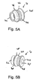
- FIGS. 5A and 5B again show perspective views of the connection sleeve 4 according to the first embodiment of the invention just described. It can be seen in particular that adjoin the conical portions 4b of the groove 4a each narrow cylindrical sections 4d. If the sleeve is fastened in the connecting device by means of the above-described clamping bar 6, the clamping bar presses in each case at a contact point on the narrow sections 4d. It can also be seen from FIG. 5B that the end 4e of the sleeve opposite the cylindrical portion 4c forms a planar surface with an opening 4f, whereby when the coaxial cable is inserted 5, the dielectric 5c is located in the opening 4f. However, it is also possible that the dielectric does not reach the opening 4f, but already ends in the region of the groove 4a.
- Figure 6 shows a perspective view of a second embodiment of the connecting device according to the invention with inserted therein and clamped by means of the clamping bar 6 sleeve 4.
- the embodiment of Figure 6 substantially corresponds to the first embodiment, with the difference that the recess 6a by a (not apparent ) Hole with closed edge has been replaced, so that the clamping bar now has two holes with a continuous border, in each of which screws 2 are used.
- the screws are tightened in Figure 6, so that a clamping is effected by the clamping bar.
- the clamping bar is curved in the region of its contact points on the connecting sleeve 4. This elastic deformation compensates for all changes in contact conditions, such as changes due to thermal expansion. This ensures high contact forces.
- the plastic deformation of the beam also provides a high balance of manufacturing tolerances.
- FIG. 7 shows a plan view from the front of the device of FIG. 6.
- a total of six contact points 3d and 6b are provided on the sleeve, with the front two contact points 3d towards the receptacle 3 and the front upper contact point 6b towards the clamping bar 6 from FIG can be seen.
- the contact points are arranged symmetrically about the vertical, passing through the sleeve center axis A.
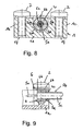
- Figure 8 shows a section through the device of Figure 7 with inserted coaxial cable 5 along a plane which is perpendicular to the axial direction of the sleeve by corresponding contact points 6b and 3d. It can be seen that the sleeve in this area is relatively thick compared to the inner conductor 5a and dielectric 5c. It can also be seen that there is no longer any coaxial outer conductor in this region, i. that the outer conductor is stripped in this area. This is also clear from FIG. 9, which is a longitudinal section of FIG. 8 along the axial direction of the sleeve and of the coaxial cable.
- the front end 5d of the coaxial outer conductor 5c does not extend through the entire sleeve 4, but already ceases shortly after the cylindrical portion 4c of the sleeve.
- the outer conductor is soldered to the sleeve.
- the Anlötung can be done before inserting the sleeve into the coupling element. But it is also possible that the sleeve is first inserted into the coupling element 1 and only then the outer conductor is soldered. It can also be seen from FIG. 9 that the clamping bar 6 presses on the sleeve 4 at the two upper, axially offset contact points 6b.
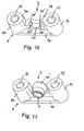
- Figures 10 and 11 show two perspective views of another embodiment of a receptacle used in the inventive device 3.
- Figure 10 shows a view of the receptacle of the coupling element without inserted sleeve 4
- the connection sleeve is positioned in the receptacle of the coupling element.
- the embodiment according to FIGS. 10 and 11 differs from the previous embodiments in that the connecting sleeve 4 instead of a profile groove 4a has a circumferential profile ring 4a ', which is inserted into corresponding notches, wherein the oblique surfaces of the notches form four contact points 3d' between the connecting sleeve 4 and coupling element 1.
- two contact point pairs are formed, wherein the contact points of each pair are axially offset from each other.
- the front pads are on the outside of a housing (not shown) and the rear pads are on the inside of a housing (not shown).
- the projections 3a and 3b are not rounded, but each having a planar, vertical termination.
- FIGS. 12A and 12B show two perspective views of the connection sleeve 4 from FIG. 11. It can be seen that the profile ring 4a 'essentially forms a bulbous region which adjoins a cylindrical end 4c of the sleeve 4. The bulbous region terminates at the opposite side of the cylindrical end 4c with a planar surface 4e, in which the opening 4f is located, in which the dielectric 5c of the coaxial cable 5 is positioned. It is also possible in this embodiment that the dielectric does not reach up to the opening 4f, but already ends in the region of the groove 4a.
- Figure 13 shows a perspective view of a connecting device with the coupling element of Figures 10 and 11, wherein in the coupling element, the sleeve 4 is clamped with the profile ring 4a 'via a clamping bar 6 in the receptacle 3.
- the clamping bar corresponds Here, the clamping bar used in the embodiments of Figures 6 to 9. It can be seen that the clamping bar is elastically deformed to effect the clamping in its center.
- the clamping bar presses here at a single contact point 6b on the profile ring 4a 'of the connecting sleeve 4. This can be seen in particular from Figure 14, which shows a plan view from the front of the device of Figure 13.
- FIG. 15 shows a plan view from the front of another embodiment of the connecting device according to the invention.
- a connection sleeve 4 with profile groove 4a is used.
- the clamping forces are generated by two jaws 3e in the receptacle 3, wherein arranged on the inside of the jaws wedges 3f engage in the groove, which in turn defined contact points are given.
- the clamping bar in this case has on the underside two flange sections 6c and 6d with wedge-shaped inner surfaces which press against the jaws 3e when the screws 2 are tightened in the flanges 1b and 1c.
- the base 1a further comprises a protrusion 1g with a rounded surface on which rest the narrow cylindrical portions 4d of the sleeve 4 and thereby form another contact with the housing.
- the embodiment of Figure 15 can also be combined with the sleeve of the embodiment of Figures 10 to 14 become. In this case, the jaws 3e instead of the wedges 3f notches on which the profile ring 4a 'of the sleeve 4 is applied.
Landscapes
- Coupling Device And Connection With Printed Circuit (AREA)
- Details Of Connecting Devices For Male And Female Coupling (AREA)
- Multi-Conductor Connections (AREA)
Description
- Die Erfindung betrifft eine Vorrichtung zum Anschluss eines Koaxialkabels, insbesondere eines Antennenkoaxialkabels, an ein Gehäuse.
- Aus dem Stand der Technik sind eine Vielzahl von Anschlussvorrichtungen zur Befestigung eines Koaxialkabels, insbesondere des Außenleiters eines Koaxialkabels, an ein metallisches Gehäuse bekannt. Beispielsweise zeigt die Druckschrift DE 102 59 803 B3, die als nächstliegender Stand der Technik angesehen wird, eine elektrische Anschlussverbindung, bei der ein gestuftes Steckelement mit einer Rändelung in eine Aufnahmeöffnung in einem Gehäuse eingepresst wird.
- Aus der Druckschrift DE 92 16 192 U1 ist ein Koaxialverbinder bekannt, bei dem ein an einem Koaxialleiter befestigter Stecker mit einer Schirmplatte verbunden wird. Hierzu wird eine Kontakthülse mit Federfingern auf dem Stecker positioniert und über eine Schirmhülse in die Schirmplatte eingeklemmt.
- Die Druckschrift DE 198 24 808 C1 zeigt eine Halterung für ein Koaxialkabel, bei der ein Koaxialaußenleiter mit einem Anschlusselement in der Form einer Klemmhülse verbunden ist, wobei die Klemmhülse Vorsprünge aufweist, welche wiederum eine Aufnahme in einer Wandung kontaktieren.
- Bei den Anschlussvorrichtungen gemäß dem Stand der Technik erweist es sich als nachteilhaft, dass zur Kontaktierung des Außenleiters das Koaxialkabel im wesentlichen in Axialrichtung eingeschoben werden muss, so dass Beschädigungen des Innenleiters beim Einführen in die Anschlussvorrichtung auftreten können.
- Aus dem Stand der Technik ist es ferner bekannt, dass der Außenleiter eines Koaxialkabels an ein Verbindungselement angelötet wird, wobei dieses Verbindungselement wiederum direkt an ein Gehäuse angeschraubt wird. Dabei ist es problematisch, dass durch den einseitigen Stromfluss vom Außenleiter über die Verschraubungsstelle das koaxiale Prinzip aufgegeben wird. Ferner kann durch Setzvorgänge in der Verschraubung der elektrische Kontakt undefiniert werden.
- Aufgabe der Erfindung ist es deshalb, eine Anschlussvorrichtung eines Koaxialkabels an einem Gehäuse zu schaffen, welche einen sicheren und einfachen Kontakt des Koaxialaußenleiters zum Gehäuse ermöglicht.
- Diese Aufgabe wird durch die unabhängigen Patentansprüche gelöst. Weiterbildungen der Erfindung sind in den abhängigen Ansprüchen definiert.
- Die erfindungsgemäße Vorrichtung umfasst ein Anschlusselement mit einer Axialachse, wobei in das Anschlusselement ein Koaxialkabel eingesetzt und leitend mit dem Außenleiter des Koaxialkabels verbunden werden kann. Dabei entspricht die Axialachse des Anschlusselementes im Wesentlichen der Axialachse des eingesetzten Koaxialkabels bzw. ist zu dieser parallel. Alternativ bildet das Anschlusselement einen Teil des Außenleiters des Koaxialkabels. Es ist ferner ein leitend mit dem Gehäuse verbindbares bzw. integral mit dem Gehäuse ausgebildetes Kupplungselement vorgesehen, welches eine Aufnahme aufweist, in welche das Anschlusselement eingesetzt werden kann. In der erfindungsgemäßen Vorrichtung weist die Aufnahme eine Einführöffnung auf, in die das Anschlusselement in eine Richtung eingefügt werden kann, welche im Wesentlichen senkrecht auf der Axialachse des Anschlusselementes steht. Ferner ist das Anschlusselement und die Aufnahme des Kupplungselementes derart geformt, das ein in die Aufnahme eingesetztes Anschlusselement eine oder mehrere vorbestimmte Kontaktstellen in der Aufnahme zur Herstellung eines leitenden Kontaktes berührt. Das Kupplungselement umfasst darüber hinaus eine Klemmeinrichtung, mit der das Anschlusselement lösbar in einer Klemmposition in der Aufnahme festgeklemmt werden kann, wobei in der Klemmposition die Klemmeinrichtung an der Einführöffnung Druck auf das Anschlusselement ausübt und dadurch das Anschlusselement an die eine oder mehreren Kontaktstellen drückt.
- Die erfindungsgemäße Vorrichtung weist eine Reihe von Vorteilen auf. Durch die definierten Kontaktstellen wird ein eindeutig definierter Stromfluss des Außenleiters zum Gehäuse festgelegt. Ferner ist die Montage des Anschlusselementes und des damit verbundenen Koaxialkabels leicht möglich, da das Koaxialkabel in einer Richtung senkrecht zur Axialachse des Kabels eingeführt werden kann. Insbesondere werden hierdurch Beschädigungen des Innenleiters vermieden. Darüber hinaus wird das Anschlusselement mit Hilfe der Klemmeinrichtung selbsttätig an die Kontaktstellen des Kupplungselementes gedrückt, wodurch ein genauer und definierter leitender Kontakt zum Gehäuse gewährleistet wird.
- In einer bevorzugten Ausführungsform sind mehrere, insbesondere vier Kontaktstellen vorgesehen, wobei ein Teil der Kontaktstellen gegenüber dem anderen Teil der Kontaktstellen in Axialrichtung des Anschlusselementes versetzt ist. Insbesondere liegt hierbei der eine Teil der Kontaktstellen an der Innenseite und der andere Teil der Kontaktstellen an der Außenseite des Gehäuses an. Hierdurch wird erreicht, dass der Außenleiterstrom, der auf der Außenseite des Außenleiters fließt, über die Kontaktstellen an der Außenseite des Gehäuses abfließt, wohingegen der Außenleiterstrom, der auf der Innenseite des Außenleiters fließt, über die Kontaktstellen an der Innenseite des Gehäuses abfließt.
- In einer weiteren Variante der Erfindung sind die Kontaktstellen symmetrisch um eine Symmetrieachse angeordnet, welche der Richtung entspricht, in die das Anschlusselement in die Einführöffnung des Kupplungselementes eingesetzt wird. Insbesondere sind die Kontaktstellen gesehen in Axialrichtung des Anschlusselementes um einen Winkel zueinander versetzt, der zwischen 90° bis 120° liegt. Die Kontaktstellen können ferner ein oder mehrere Kontaktstellenpaare bilden, wobei jedes Kontaktstellenpaar zwei in Axialrichtung des Anschlusselementes miteinander ausgerichtete Kontaktstellen umfasst.
- In einer bevorzugten Ausführungsform ist das Anschlusselement eine Anschlusshülse mit einer umlaufenden Profilnut, welche mit einem oder mehreren Flächenelementen in der Aufnahme zusammenwirkt, so dass die eine oder die mehreren Kontaktstellen Berührungsstellen zwischen den Flächenelementen und der Profilnut sind. Insbesondere ist die Profilnut keilförmig ausgestaltet, wobei die konischen Flanken der Profilnut an entsprechend angeordneten Zylinderflächen in der Aufnahme aufliegen. Hierdurch wird auf einfache Weise die axiale Befestigungsposition des Anschlusselementes in der Aufnahme durch Formschluß festgelegt. Die konischen Flanken der Profilnut sind hierbei vorzugsweise in einem Winkel von +30° bzw. -30° gegenüber der Axialachse der Hülse geneigt. In einer besonders bevorzugten Variante sind die Zylinderflächen Flächenabschnitte eines oder mehrerer Zylinder, welche gegenüber der Achse, in deren Richtung das Anschlusselement in die Einführöffnung eingesetzt wird, geneigt sind, insbesondere in einem.Winkel von +45° bzw. -45°, wobei die Achse des oder der Zylinder in einer Ebene senkrecht zur Axialachse der Hülse liegt. Darüber hinaus kann die Aufnahme zwei gegenüberliegende Vorsprünge aufweisen, welche in die keilförmige Profilnut des Anschlusselementes eingreifen.
- In einer alternativen Ausgestaltung der erfindungsgemäßen Vorrichtung ist das Anschlusselement eine Anschlusshülse mit einem umlaufenden Profilring, welcher mit einer oder mehreren Einkerbungen in der Aufnahme derart zusammenwirkt, dass der oder die Kontaktstellen Berührungsstellen der Einkerbungen an dem Profilring sind. Auch bei dieser Ausgestaltung wird auf einfache Weise eine.axiale Fixierung der Anschlusshülse in der Aufnahme erreicht.
- In einer weiteren Ausgestaltung ist die Aufnahme eine zwischen zwei Flanschabschnitten gebildete Aussparung, wobei an den Flanschabschnitten ein sich über die Aussparung erstreckender Klemmbalken lösbar befestigt ist, welcher zumindest mittelbar auf das Anschlusselement drückt. Insbesondere drückt der Klemmbalken an einer oder mehreren, vorzugsweise zwei Kontaktstellen auf das Anschlusselement. Der Klemmbalken ist dabei vorzugsweise wenigstens an einem der Flanschabschnitte angeschraubt. Durch die Verwendung eines Klemmbalkens wird eine einfache Montage des Anschlusselementes, insbesondere unter Verwendung eines herkömmlichen Schraubenziehers, in der Aufnahme gewährleistet.
- In einer weiteren Variante kann der Klemmbalken derart in dem Kupplungselement vormontiert werden, dass er an einem Ende um eine Axialachse eines Flanschabschnitts bis in eine Anschlagsposition gedreht werden kann, wobei der Klemmbalken zur Bewirkung der Klemmung in der Anschlagsposition fixiert werden kann. Vorzugsweise kontaktiert in der. Anschlagsposition ein am entgegengesetzten Ende des Klemmbalkens angeordneter Eingriffsabschnitt den anderen Flanschabschnitt, jedoch ist es auch möglich, dass der Klemmbalken auf andere Weise fixiert wird, ohne dass das entgegengesetzte Ende des Klemmbalkens den anderen Flanschabschnitt berührt. Durch die Vormontage des Klemmbalkens wird auf einfache Weise eine Anordnung des Klemmbalkens in einer Position gewährleistet, in welcher der Balken zur Klemmung fixiert wird. Insbesondere weist der Klemmbalken an einem Ende ein Loch mit geschlossenem Rand auf, in dem ein erster Schraubbolzen zum Verschrauben mit einem Flanschabschnitt eingesetzt ist, wobei der Eingriffsabschnitt ein an dem entgegengesetzten Ende des Klemmbalkens angeordnetes, zum Rand des Klemmbalkens geöffnetes Loch ist, so dass durch eine Schwenkbewegung des Klemmbalkens das geöffnete Loch auf einen zweiten Schraubbolzen zum Verschrauben mit dem anderen Flanschabschnitt positioniert werden kann, wobei die Klemmung durch Festziehen der Schraubbolzen bewirkt wird.
- Vorzugsweise weist der Klemmbalken einen Vorsprung auf, mit dem er durch die Finger eines Benutzer gedreht werden kann. In einer bevorzugten Variante drückt der Klemmbalken zur Bewirkung der Klemmung direkt auf das Anschlusselement. Es ist jedoch auch möglich, dass der Klemmbalken zur Bewirkung der Klemmung auf eine oder mehrere Klemmbacken in der Aufnahme drückt, wobei die Klemmbacken das Anschlusselement an einer oder mehreren Kontaktstellen kontaktieren.
- Der Klemmbalken ist vorzugsweise zur Bewirkung der Klemmung elastisch verformbar, wobei durch die Verformbarkeit ein hoher Toleranzausgleich geschaffen wird und alle Veränderungen in den Kontaktbedingungen, insbesondere durch Setzen und Wärmeausdehnung verursachte Veränderungen, ausgeglichen werden. Hierdurch werden immer hohe Kontaktkräfte sichergestellt.
- Vorzugsweise besteht der Klemmbalken aus einem nicht leitenden Material, insbesondere aus Glasfaserkunststoff. Es ist jedoch auch denkbar, dass der Klemmbalken aus Metall, vorzugsweise aus Federbronze besteht. In diesem Falle werden weitere elektrische Kontaktstellen neben den bereits vorhandenen Kontaktstellen in der Aufnahme geschaffen. Der Klemmbalken kann ferner gegenüber den Flanschabschnitten und/oder dem Anschlusselement isoliert sein.
- Das Anschlusselement kann ein einfach zu fertigendes metallisches Drehteil sein. Das Kupplungselement ist insbesondere integral mit dem Gehäuse in der Form eines Gussteils ausgebildet. Ferner ist der Außenleiter des Koaxialkabels vorzugsweise in das Anschlusselement eingelötet.
- Die Erfindung betrifft neben der gerade beschriebenen Anschlussvorrichtung auch ein Gehäuse, insbesondere ein Gehäuse eines Phasenschiebers einer Antennenanordnung, welche die erfindungsgemäße Anschlussvorrichtung umfasst. Hierbei sind die Kontaktstellen der Anschlussvorrichtung vorzugsweise.derart angeordnet, dass ein Teil der Kontaktstellen benachbart zur Innenseite des Gehäuses und ein anderer Teil der Kontaktstellen benachbart zur Außenseite des Gehäuses liegt.
- Ausführungsbeispiele der Erfindung werden nachfolgend detailliert anhand der beigefügten Figuren beschrieben.
- Es zeigen:
- Figur 1:
- eine perspektivische Ansicht einer ersten Ausführungsform der erfindungsgemäßen Anschlussvorrichtung mit eingesetztem Koaxialkabel;
- Figur 2:
- eine Draufsicht auf die Vorrichtung der Figur 1 ohne Klemmeinrichtung;
- Figur 3:
- eine perspektivische Ansicht der Aufnahme der Anschlussvorrichtung aus Figur 1 ohne eingesetzte Hülse;
- Figur 4:
- eine perspektivische Ansicht der Aufnahme der Anschlussvorrichtung aus Figur 1 mit eingesetzter Hülse;
- Figuren 5A und 5B:
- zwei perspektivische Ansichten der in der Vorrichtung der Figur 1 verwendeten Anschlusshülse;
- Figur 6:
- eine perspektivische Ansicht einer zweiten Ausführungsform der erfindungsgemäßen Anschlussvorrichtung;
- Figur 7:
- eine Draufsicht von vorne auf die Vorrichtung der Figur 6;
- Figur 8:
- eine Schnittansicht durch die Vorrichtung der Figur 6 mit eingesetztem Koaxialkabel entlang einer Ebene, welche senkecht auf der Axialachse des Koaxialkabels steht und mittig durch die Aufnahme verläuft;
- Figur 9:
- eine Schnittansicht senkrecht zum Schnitt der Figur 8 entlang des Innenleiters des eingesetzten Koaxialkabels;
- Figur 10:
- eine perspektivische Ansicht einer Aufnahme in einer dritten Ausführungsform der erfindungsgemäßen Vorrichtung ohne eingesetzte Hülse;
- Figur 11:
- eine perspektivische Ansicht der Aufnahme gemäß Figur 10 mit eingesetzter Hülse;
- Figuren 12A und 12B:
- perspektivische Ansichten der in Figur 11 gezeigten Hülse;
- Figur 13:
- eine perspektivische Ansicht der dritten Ausführungsform der erfindungsgemäßen Anschlussvorrichtung mit festgeklemmter Hülse;
- Figur 14:
- eine Draufsicht von vorne auf die Vorrichtung der Figur 13; und
- Figur 15:
- eine Draufsicht von vorne auf eine vierte Ausführungsform der erfindungsgemäßen Anschlussvorrichtung.
- Die in Figur 1 gezeigte erste Ausführungsform der erfindungsgemäßen koaxialen Anschlussvorrichtung umfasst ein Kupplungselement 1, welches vorzugsweise Teil eines metallischen Gehäuses ist und integral als Gussform mit dem Gehäuse ausgebildet ist. Das Kupplungselement besteht beispielsweise aus Aluminium oder Zink, und das Gehäuse ist z.-B. ein Gehäuse eines in Hochfrequenz-Antennenanordnungen verwendeten Phasenschiebers, mit dem in Mobilfunkantennen eine Phasenverschiebung der Strahlung der einzelnen Antennenelemente bewirkt wird. Das Kupplungselement umfasst einen Sockelbereich 1a, aus dem sich zwei Flanschabschnitte 1b und 1c nach oben erstrecken. An die Flanschabschnitte schließen sich jeweils Wandungen 1d und 1e an, welche Teile des Gehäuses bilden und sich zu weiteren Flanschabschnitten erstrecken. Die Flanschabschnitte 1b und 1c umfassen jeweils eine Bohrung, in welche entsprechende Schraubbolzen 2 eingeschraubt sind. Zwischen den Flanschen 1b und 1c ist eine Aufnahme 3 gebildet, welche links und rechts durch zwei, sich jeweils an einem Flanschabschnitt anschließende Vorsprünge 3a und 3b begrenzt wird. In die Aufnahme ist eine Anschlusshülse 4 von oben über die zwischen den Flanschen gebildete Einführöffnung eingesetzt. Die Anschlusshülse besteht aus leitfähigem Material, beispielsweise aus verzinntem Messing oder Neusilber, und sie weist eine Profilierung in der Form einer Nut 4a auf, wobei sich die Vorsprünge 3a und 3b in die Nut erstrecken, wodurch das Entfernen der Hülse aus der Aufnahme 3 in axialer Richtung verhindert wird. In die Hülse ist ein Koaxialkabel 5 mit Innenleiter 5a, Außenleiter 5b und dazwischen liegendem Dielektrikum 5c eingesetzt. Der Außenleiter wird hierbei vorzugsweise in die Hülse 4 eingelötet. Die Aufnahme 3 sowie die Hülse 4 sind derart geformt, dass definierte Kontaktstellen zwischen Hülse und Aufnahme festgelegt sind, so dass ein definierter Stromfluss vom Außenleiter 5b zum Gehäuse existiert, wie im Folgenden noch näher beschrieben wird.
- An der Oberseite der Flanschabschnitte 1b und 1c befindet sich eine Klemmeinrichtung in der Form eines Klemmbalkens 6, der in Figur 1 in geöffneter, nicht klemmender Position gezeigt ist. Der Klemmbalken umfasst an einem Ende ein (nicht aus Figur 1 ersichtliches) Loch, in das eine Schraube 2 eingesetzt. Die Schraube ist soweit in den Flansch 1c eingeschraubt, dass der Klemmbalken zwischen Unterseite der Schraube 2 und Oberseite des Flansches 1c fixiert wird. Die Schraube ist in Figur 1 jedoch nicht festgezogen, so dass noch eine Verdrehung des Klemmbalkens 6 um die Achse der Schraube 2 ermöglicht wird. Der Klemmbalken 6 weist an seinem vorderen Ende eine Aussparung 6a auf, welche zu einem Rand des Klemmbalkens hin geöffnet ist. Durch die Aussparung 6a wird ein Eingriffsabschnitt gebildet, der durch Verschwenken des Klemmbalkens 6 hin zum Flanschabschnitt 1b in das Außengewinde einer weiteren, in die Bohrung des Flanschabschnittes 1b eingesetzten Schraube 2 eingreift. In dieser Eingriffsposition erstreckt sich der Klemmbalken 6 über die Aufnahme 3. Werden anschließend die beiden Schrauben 2 festgezogen, drückt der Klemmbalken an zwei definierte Auflagepunkte der Hülse 4. Hierdurch wird die Hülse fest an die Kontaktstellen in der Aufnahme gedrückt, wodurch ein guter leitender Kontakt der Hülse zu den Kontaktstellen in der Aufnahme hergestellt wird.
- Der Klemmbalken kann aus leitendem Material, z. B. aus Federbronze, bestehen, so dass zwei weitere elektrische Kontaktstellen der Hülse zum Klemmbalken und damit zum Gehäuse ermöglicht werden. Alternativ kann der Klemmbalken auch aus nicht leitendem oder nicht metallischem Material, wie z.B. Glasfaserkunststoff, bestehen, so dass keine weiteren elektrischen Kontaktpunkte zwischen Hülse und Klemmbalken bereitgestellt werden. Es ist auch möglich, dass der Klemmbalken zwar aus metallischem Material besteht, jedoch gegenüber der Hülse und/oder den Flanschabschnitten isoliert ist. Durch die Anschlussvorrichtung der Figur 1 kann das Koaxialkabel 5 einfach durch eine Fügebewegung senkrecht zur Axialrichtung des Kabels in das Kupplungselement 1 eingefügt werden, wodurch Beschädigungen des Innenleiters 5a vermieden werden. Ferner kann auf einfache Weise ein lösbarer elektrischer Kontakt zwischen dem Außenleiter 5b des Kabels 5 und dem Kupplungselement 1 gewährleistet werden.
- Figur 2 zeigt eine Draufsicht auf die Vorrichtung der Figur 1, wobei die oberen Schrauben 2 und der Klemmbalken 6 weggelassen wurden. Man erkennt insbesondere, dass die Nut 4a der Hülse 4 zwei gegenüberliegende, umlaufende konische Flanken 4b aufweist, in welche die vorderen abgerundeten Ränder der Vorsprünge 3a und 3b eingreifen. Die Ränder kontaktieren dabei nie die Flanken, da durch die definierten (nicht aus Figur 2 ersichtlichen) Kontaktstellen zwischen Hülse und Aufnahme eine Selbstzentrierung der Hülse in der Aufnahme erreicht wird, so dass es ausschließlich zu einer Kontaktierung der Hülse an den definierten Kontaktstellen kommt. Die Vorsprünge dienen somit nur zur groben Fixierung, damit die Hülse leicht montiert werden kann und nicht axial entweicht, bevor die Schrauben 2 zur Fixierung des Klemmbalkens angezogen werden. Man erkennt ferner, dass die Hülse 4 einen vorderen zylindrischen Abschnitt 4c aufweist, in dem der Außenleiter 5b des Koaxialkabels 5 eingesetzt ist. Darüber hinaus sind die Öffnungen 1f in den Flanschabschnitten 1b bzw. 1c ersichtlich.
- Figuren 3 und 4 zeigen perspektivische Ansichten des die Aufnahme bildenden Bereiches des Kupplungselementes 1. Figur 3 zeigt hierbei eine Ansicht ohne eingesetzte Anschlusshülse 4, wohingegen in Figur 4 die Anschlusshülse in die Aufnahme 3 eingesetzt ist. Aus Figur 3 wird die detaillierte Form der Aufnahme ersichtlich. Die Aufnahme umfasst in einem unteren Bereich eine kreisförmige Aussparung 3c, an die sich vier schräg liegende Zylinderflächen 3d anschließen. Es sind jeweils zwei Zylinderflächen auf der linken und rechten Seite der Aussparung 3c vorgesehen. Die Zylinderflächen 3d auf der rechten Seite liegen hierbei auf einem Zylinder mit dem Durchmesser 4 mm, wobei die Zylinderachse gegenüber einer vertikalen Achse, welche senkrecht auf dem Sockel 1a steht, um +45° geneigt ist und in einer mittig durch die beiden Flanschabschnitte 1b und 1c verlaufenden Ebene liegt. Analog liegen die linken Zylinderflächen 3d auf einem Zylinder, der gegenüber der vertikalen Achse um -45° geneigt ist. An die Zylinderflächen 3d liegen die konischen Flächen 4b der Nut 4a an, wobei die konischen Flächen gegenüber einer auf der Axialachse der Hülse 4 senkrecht stehenden Achse um +30° bzw. -30° geneigt sind. Durch das Zusammenwirken der konischen Flächen 4b mit den Zylinderflächen 3d werden auf diese Weise vier punktförmige Kontaktstellen zwischen der Hülse 4 und dem Kupplungselement 1 gebildet. Die beiden vorderen Zylinderflächen 3d liegen hierbei auf der Außenseite des (nicht gezeigten) Gehäuses, wohingegen die hinteren beiden Zylinderflächen 3d auf der Innenseite des Gehäuses liegen. Somit fließt der Außenleiterstrom, der auf der Innenseite des Außenleiters fließt, über die Zylinderflächen der Gehäuseinnenseite ab, wohingegen der Außenleiterstrom auf der Außenseite des Außenleiters über die Zylinderflächen auf der Gehäuseaußenseite abfließt.
- Figuren 5A und 5B zeigen nochmals perspektivische Ansichten der Anschlusshülse 4 gemäß der soeben beschriebenen ersten Ausführungsform der Erfindung. Man erkennt insbesondere, dass sich an die konischen Abschnitte 4b der Nut 4a jeweils schmale zylindrische Abschnitte 4d anschließen. Ist die Hülse in der Anschlussvorrichtung mittels des zuvor beschriebenen Klemmbalkens 6 befestigt, drückt der Klemmbalken jeweils an einen Berührpunkt auf den schmalen Abschnitten 4d. Aus Figur 5B ist ferner ersichtlich, dass das dem zylindrischen Abschnitt 4c gegenüberliegende Ende 4e der Hülse eine planare Fläche mit einer Öffnung 4f bildet, wobei sich bei eingesetztem Koaxialkabel 5 das Dielektrikum 5c in der Öffnung 4f befindet. Es ist jedoch auch möglich, dass das Dielektrikum nicht bis zur Öffnung 4f reicht, sondern bereits im Bereich der Nut 4a endet.
- Figur 6 zeigt eine perspektivische Ansicht einer zweiten Ausführungsform der erfindungsgemäßen Anschlussvorrichtung mit darin eingesetzter und mit Hilfe des Klemmbalkens 6 festgeklemmter Hülse 4. Die Ausführungsform der Figur 6 entspricht im Wesentlichen der ersten Ausführungsform, mit dem Unterschied, dass die Aussparung 6a durch ein (nicht ersichtliches) Loch mit geschlossenem Rand ersetzt wurde, so dass der Klemmbalken nun zwei Löcher mit durchgehender Umrandung aufweist, in die jeweils Schrauben 2 eingesetzt sind. Die Schrauben sind in Figur 6 festgezogen, so dass durch den Klemmbalken eine Klemmung bewirkt wird. Insbesondere ist ersichtlich, dass der Klemmbalken im Bereich seiner Kontaktstellen an der Anschlusshülse 4 gewölbt ist. Durch diese elastische Verformung werden alle Veränderungen in den Kontaktbedingungen ausgeglichen, beispielsweise durch Wärmeausdehnung entstehende Veränderungen. Es werden somit hohe Kontaktkräfte sichergestellt. Die plastische Verformung des Balkens schafft ferner einen hohen Ausgleich von Fertigungstoleranzen.
- Figur 7 zeigt eine Draufsicht von vorne auf die Vorrichtung der Figur 6. Es sind insgesamt sechs Kontaktstellen 3d und 6b auf der Hülse vorgesehen, wobei aus Figur 7 die vorderen zwei Kontaktstellen 3d hin zur Aufnahme 3 sowie die vordere obere Kontaktstelle 6b hin zum Klemmbalken 6 ersichtlich sind. Die Kontaktstellen sind symmetrisch um die vertikale, durch die Hülsenmitte gehende Achse A angeordnet.
- Figur 8 zeigt einen Schnitt durch die Vorrichtung der Figur 7 mit eingesetztem Koaxialkabel 5 entlang einer Ebene, die senkrecht zur Axialrichtung der Hülse durch entsprechende Kontaktstellen 6b und 3d verläuft. Man erkennt, dass die Hülse in diesem Bereich im Vergleich zum Innenleiter 5a und Dielektrikum 5c relativ dick ist. Ferner ist ersichtlich, dass sich in diesem Bereich kein koaxialer Außenleiter mehr befindet, d.h. dass der Außenleiter in diesem Bereich abisoliert ist. Dies ergibt sich auch nochmals aus der Figur 9, welche ein Längsschnitt der Figur 8 entlang der Axialrichtung der Hülse und des Koaxialkabels ist. Man erkennt, dass sich das vordere Ende 5d des Koaxialaußenleiters 5c nicht durch die gesamte Hülse 4 erstreckt, sondern bereits kurz nach dem zylindrischen Abschnitt 4c der Hülse aufhört. In dem Bereich, in dem der Koaxialaußenleiter 5b in dem Abschnitt 4c aufgenommen ist, erfolgt die Anlötung des Außenleiters an die Hülse. Die Anlötung kann vor dem Einsetzen der Hülse in das Kupplungselement erfolgen. Es ist aber auch möglich, dass die Hülse zunächst in das Kupplungselement 1 eingesetzt wird und erst anschließend der Außenleiter festgelötet wird. Aus Figur 9 ist ferner ersichtlich, dass der Klemmbalken 6 an den zwei oberen, axial versetzten Kontaktstellen 6b auf die Hülse 4 drückt.
- Figuren 10 und 11 zeigen zwei perspektivische Ansichten einer weiteren Ausführungsform einer in der erfindungsgemäßen Vorrichtung verwendeten Aufnahme 3. Figur 10 zeigt eine Ansicht der Aufnahme des Kupplungselementes ohne eingesetzte Hülse 4, wohingegen in Figur 11 die Anschlusshülse in der Aufnahme des Kupplungselementes positioniert ist. Die Ausführungsform gemäß Figuren 10 und 11 unterscheidet sich von den vorhergehenden Ausführungsformen darin, dass die Anschlusshülse 4 statt einer Profilnut 4a einen umlaufenden Profilring 4a' aufweist, der in entsprechende Einkerbungen eingesetzt wird, wobei die schrägen Flächen der Einkerbungen vier Kontaktstellen 3d' zwischen Anschlusshülse 4 und Kupplungselement 1 bilden. Analog zu den vorangegangenen Ausführungsformen werden zwei Kontaktstellenpaare gebildet, wobei die Kontaktstellen jedes Paares axial zueinander versetzt sind. Insbesondere liegen die vorderen Kontaktstellen an der Außenseite eines (nicht gezeigten) Gehäuses und die hinteren Kontaktstellen befinden sich an der Innenseite eines (nicht gezeigten) Gehäuses. Ein weiterer Unterschied zu den vorhergehenden Ausführungsformen besteht darin, dass die Vorsprünge 3a und 3b nicht abgerundet sind, sondern jeweils einen planaren, vertikalen Abschluss aufweisen.
- Figuren 12A und 12B zeigen zwei perspektivische Ansichten der Anschlusshülse 4 aus Figur 11. Man erkennt, dass der Profilring 4a' im Wesentlichen einen bauchigen Bereich bildet, der sich an ein zylindrisches Ende 4c der Hülse 4 anschließt. Der bauchige Bereich endet an der gegenüberliegenden Seite des zylindrischen Endes 4c mit einer planaren Fläche 4e, in der sich die Öffnung 4f befindet, in die das Dielektrikum 5c des Koaxialkabels 5 positioniert wird. Es ist auch bei dieser Ausführungsform möglich, dass das Dielektrikum nicht bis zur Öffnung 4f reicht, sondern bereits im Bereich der Nut 4a endet.
- Figur 13 zeigt eine perspektivische Ansicht einer Anschlussvorrichtung mit dem Kupplungselement aus den Figuren 10 und 11, wobei in dem Kupplungselement die Hülse 4 mit dem Profilring 4a' über einen Klemmbalken 6 in der Aufnahme 3 eingeklemmt ist. Der Klemmbalken entspricht hierbei dem in den Ausführungsformen der Figuren 6 bis 9 verwendeten Klemmbalken. Es ist ersichtlich, dass der Klemmbalken zur Bewirkung der Klemmung in seiner Mitte elastisch verformt ist. Der Klemmbalken drückt hierbei an einer einzigen Kontaktstelle 6b auf den Profilring 4a' der Anschlusshülse 4. Dies erkennt man insbesondere auch aus Figur 14, welche eine Draufsicht von vorne auf die Vorrichtung der Figur 13 zeigt. Es ist ersichtlich, dass der Profilring 4a' an seinem obersten Punkt 6b an dem verformten Klemmbalken 6 anliegt und dass der Profilring 4a' ferner an den Kontaktstellen 3d' in den Einkerbungen aufliegt. Es werden.somit vier Kontaktstellen des Profilrings zur Aufnahme 3 und eine Kontaktstelle des Profilrings zum Klemmbalken 6 geschaffen.
- Figur 15 zeigt eine Draufsicht von vorne auf eine weitere Ausführungsform der erfindungsgemäßen Anschlussvorrichtung. Analog zu den Ausführungsformen der Figuren 1 bis 9 wird eine Anschlusshülse 4 mit Profilnut 4a verwendet. Im Gegensatz zu jenen Ausführungsformen werden die Klemmkräfte jedoch durch zwei Klemmbacken 3e in der Aufnahme 3 erzeugt, wobei an der Innenseite der Backen angeordnete Keile 3f in die Nut eingreifen, wodurch wiederum definierte Kontaktstellen vorgegeben werden. Der Klemmbalken weist hierbei an der Unterseite zwei Flanschabschnitte 6c und 6d mit keilförmigen Innenflächen auf, die gegen die Backen 3e drücken, wenn die Schrauben 2 in den Flanschen 1b und 1c festgezogen werden. Der Sockel 1a umfasst ferner eine Erhebung 1g mit einer abgerundeten Oberfläche, auf der die schmalen zylindrischen Abschnitte 4d der Hülse 4 aufliegen und hierdurch einen weiteren Kontakt zum Gehäuse bilden. Die Ausführungsform der Figur 15 kann auch mit der Hülse aus der Ausführungsform der Figuren 10 bis 14 kombiniert werden. In diesem Fall weisen die Klemmbacken 3e antstatt der Keile 3f Einkerbungen auf, an denen der Profilring 4a' der Hülse 4 anliegt.
Claims (27)
- Vorrichtung zum Anschluss eines Koaxialkabels (5), insbesondere eines Antennenkoaxialkabels, an einem Gehäuse, wobei die Vorrichtung folgende Merkmale aufweist:- es ist ein hülsenförmiges Anschlusselement (4) mit einer Axialachse vorgesehen,- das Anschlusselement (4) ist mit dem Außenleiter (5b) des Koaxialkabels (5) verbunden oder verbindbar, wozu das Koaxialkabel (5) in das hülsenförmige Aufnahmeelement (4) eintaucht oder darin einsetzbar oder damit verbindbar ist, oder das Anschlusselement (4) einen Teil des Außenleiters (5b) des Koaxialkabels (5) bildet,- es ist ein leitend mit dem Gehäuse verbindbares oder am Gehäuse integral ausgebildetes Kupplungselement (1) vorgesehen,- das Kupplungselement (1) weist eine Aufnahme (3) zum Einsetzen des Anschlusselementes (4) auf,- die Aufnahme (3) des Kupplungselementes (1) weist eine Einführöffnung auf, in welche das Anschlusselement (4) in einer Richtung eingesetzt werden kann, welche im Wesentlichen senkrecht zur Axialachse des Anschlusselementes (4) verläuft,- das Kupplungselement (1) umfasst eine Klemmeinrichtung (6), mit der das Anschlusselement (4) lösbar in einer Klemmposition in der Aufnahme (3) festgeklemmt werden kann, wobei in der Klemmposition die Klemmeinrichtung (6) an der Einführöffnung Druck auf das Anschlusselement (4) ausübt und dadurch das Anschlusselement (4) an die mehreren Kontaktstellen (3d, 3d') drückt,- das Aufnahmeelement (4) und das Kupplungselement (1) sind mit ineinander greifenden Vorsprüngen und Vertiefungen versehen,a) wobei das Aufnahmeelement (4) mit einer in Umfangsrichtung verlaufenden Profilnut (4a) versehen ist, wodurch in Axialrichtung versetzt liegende radial vorstehende Ringstege an dem Aufnahmeelement (4) gebildet sind, in welche an dem Kupplungselement (1) ausgebildete Vorsprünge in die Profilnut (4a) zwischen den Ringstegen eintauchen, oderb) wobei das Kupplungselement (1) mit einer in Umfangsrichtung versehenen nutförmigen Einkerbung (3a, 3b) versehen ist, wodurch in Axialrichtung versetzt liegende radial vorstehende Vorsprünge an dem Kupplungselement (1) gebildet sind, wobei das Aufnahmeelement (4) einen in Umfangsrichtung verlaufenden Profilring oder Profilvorsprung aufweist, der in die nutförmige Einkerbung (3a, 3b) am Kupplungselement (1) eintaucht,- die Profilnut (4a) bzw. die nutförmige Einkerbung (3a, 3b) weisen in Axialrichtung des Anschlusselementes (4) versetzt liegende Flanken (4b; 3d') auf, die gegensinnig divergierend ausgebildet sind, und- die Kontaktstellen (3d; 3d') sind an dem Kontaktelement (1) so ausgebildet und/oder so angeordnet, dass sie die hülsenförmige Aufnahmeeinrichtung (4) an den divergierenden Flanken (4b) der Profilnut (4a) bzw. des Profilringes (4a') teils in Axialrichtung und teils in Umfangsrichtung der Anschlusshülse (4) versetzt liegend kontaktieren.
- Vorrichtung nach Anspruch 1, dadurch gekennzeichnet, dass mehrere, insbesondere vier Kontaktstellen (3d, 3d') vorgesehen sind, wobei zumindest ein Paar von Kontaktstellen (3d, 3d') in Axialrichtung versetzt zueinander und in Umfangsrichtung bezogen auf die hülsenförmige Anschlusseinrichtung (4) in gleicher Position vorgesehen sind.
- Vorrichtung nach Anspruch 2, dadurch gekennzeichnet, dass der eine Teil der Kontaktstellen (3d, 3d') an der Innenseite des Gehäuses und der andere Teil der Kontaktstellen (3d, 3d') an der Außenseite des Gehäuses liegt.
- Vorrichtung nach einem der vorhergehenden Ansprüche, dadurch gekennzeichnet, dass die Kontaktstellen (3d, 3d') symmetrisch um eine Symmetrieachse angeordnet sind, welche der Richtung entspricht, in die das Anschlusselement (4) in die Aufnahme (3) eingesetzt wird.
- Vorrichtung nach Anspruch 4, dadurch gekennzeichnet, dass die Kontaktstellen (3d, 3d') gesehen in Axialrichtung des Anschlusselementes (4) um einen Winkel zwischen 90° und 120° zueinander versetzt sind.
- Vorrichtung nach einem der Ansprüche 1 bis 5, dadurch gekennzeichnet, dass im Falle eines hülsenförmige Aufnahmeelement (4) mit einer umlaufenden Profilnut (4a) die Kontaktstellen (3d) am Kontaktelement (1) eine Teilstruktur einer Zylinderoberfläche (3d) darstellen.
- Vorrichtung nach Anspruch 6, dadurch gekennzeichnet, dass die konischen Flanken (4b) der Profilnut (4a) in einem Winkel von +30° und/oder -30° gegenüber der Axialachse der Hülse (4) geneigt sind.
- Vorrichtung nach Anspruch 6 oder 7, dadurch gekennzeichnet, dass die Zylinderflächen (3d) Flächenabschnitte eines oder.mehrerer Zylinder darstellen, welche gegenüber der Achse, in deren Richtung das Anschlusselement (4) in die Einführöffnung der Aufnahme (3) eingesetzt wird, geneigt sind, insbesondere in einem Winkel von +45° und/oder -45°, wobei die Achse des oder der Zylinder in einer Ebene senkrecht zur Axialachse der Hülse liegt.
- Vorrichtung nach einem der Ansprüche 1 bis 8, dadurch gekennzeichnet, dass die Aufnahme (3) zwei gegenüberliegende Vorsprünge (3a, 3b) aufweist, welche in die Profilnut (4a) eines in der Aufnahme (3) eingesetzten Anschlusselementes (4) eintaucht.
- Vorrichtung nach einem der Ansprüche 1 bis 5, dadurch gekennzeichnet, dass im Falle eines hülsenförmigen Aufnahmeelementes (1) mit einem umlaufenden Profilring (4a') die nutförmigen Einkerbungen am Kontaktelement (1) ebene Flächen bilden.
- Vorrichtung nach einem der vorhergehenden Ansprüche, dadurch gekennzeichnet, dass die Aufnahme (3) eine zwischen zwei Flanschabschnitten (1b 1c) gebildete Aussparung ist, wobei an den Flanschabschnitten (1b, 1c) ein sich über die Aussparung erstreckender Klemmbalken (6) lösbar befestigt ist, der zumindest mittelbar auf das Anschlusselement (4) drückt.
- Vorrichtung nach Anspruch 11, dadurch gekennzeichnet, dass der Klemmbalken (6) an einer oder mehreren Kontaktstellen (6b), vorzugsweise an zwei Kontaktstellen, auf das Anschlusselement (4) drückt.
- Vorrichtung nach Anspruch 11 oder 12, dadurch gekennzeichnet, dass der Klemmbalken (6) an wenigstens einem der Flanschabschnitte (1b, 1c) angeschraubt ist.
- Vorrichtung nach einem der Ansprüche 11 bis 13, dadurch gekennzeichnet, dass der Klemmbalken (6) derart an dem Kupplungselement (1) vormontiert werden kann, dass er an einem Ende um eine Axialachse eines Flanschabschnittes (1c) bis in eine Anschlagsposition verschwenkt werden kann, wobei der Klemmbalken (6) zur Bewirkung der Klemmung in der Anschlagsposition fixiert werden kann und wobei in der Anschlagsposition vorzugsweise ein am entgegengesetzten Ende des Klemmbalkens (6) angeordneter Eingriffsabschnitt (6a) den anderen Flanschabschnitt (1b) kontaktiert.
- Vorrichtung nach Anspruch 14, dadurch gekennzeichnet, dass der Klemmbalken (6) an einem Ende ein Loch mit geschlossenem Rand aufweist, in das ein erster. Schraubbolzen (2) zum Verschrauben mit dem einen Flanschabschnitt (1c) eingesetzt ist, wobei der Eingriffsabschnitt (6a) ein am entgegengesetzten Ende des Klemmbalkens (6) angeordnetes, zum Rand des Klemmbalkens (6) geöffnetes Loch (6a) ist, so dass durch eine Schwenkbewegung des Klemmbalkens (6) um den ersten Schraubbolzen (2) das geöffnete Loch (6a) auf einen zweiten Schraubbolzen (2) zum Verschrauben mit dem anderen Flanschabschnitt (1b) positioniert werden kann, wobei die Klemmung durch das Festziehen der beiden Schraubbolzen (2) bewirkt wird.
- Vorrichtung nach Anspruch 14 oder 15, dadurch gekennzeichnet, dass der Klemmbalken (6) einen Vorsprung aufweist, mit dem der Klemmbalken (6) mit Hilfe der Finger eines Benutzers gedreht werden kann.
- Vorrichtung nach einem der Ansprüche 11 bis 16, dadurch gekennzeichnet, dass der Klemmbalken (6) zur Bewirkung der Klemmung direkt auf das Anschlusselement (4) drückt.
- Vorrichtung nach einem der Ansprüche 11 bis 16, dadurch gekennzeichnet, dass der Klemmbalken (6) zur Bewirkung der Klemmung auf eine oder mehrere Klemmbacken (3e) in der Aufnahme (3) drückt, wobei die Klemmmbacken (3e) das Anschlusselement (4) an einer oder mehreren. Kontaktstellen kontaktieren.
- Vorrichtung nach einem der Ansprüche 11 bis 18, dadurch gekennzeichnet, dass der Klemmbalken (6) zur Bewirkung der Klemmung elastisch verformbar ist.
- Vorrichtung nach einem der Ansprüche 11 bis 19, dadurch gekennzeichnet, dass der Klemmbalken (6) aus einem nicht leitenden Material, insbesondere aus Glasfaserkunststoff, besteht.
- Vorrichtung nach einem der Ansprüche 11 bis 20, dadurch gekennzeichnet, dass der Klemmbalken (6) aus leitfähigem Material, insbesondere aus Metall, vorzugsweise aus Federbronze, besteht.
- Vorrichtung nach einem der Ansprüche 11 bis 21, dadurch gekennzeichnet, dass der Klemmbalken (6) gegenüber den Flanschabschnitten (1b, 1c) und/oder gegenüber dem Anschlusselement (4) isoliert ist.
- Vorrichtung nach einem der vorhergehenden Ansprüche, dadurch gekennzeichnet, dass das Anschlusselement (4) ein metallisches Drehteil, insbesondere aus verzinntem Messing und/oder Neusilber, ist.
- Vorrichtung nach einem der vorhergehenden Ansprüche, dadurch gekennzeichnet, dass das Kupplungselement (1) integral mit dem Gehäuse in der Form eines Gussteils ausgebildet ist.
- Vorrichtung nach einem der vorhergehenden Ansprüche, dadurch gekennzeichnet, dass der Außenleiter (5b) des Koaxialkabels (5) in dem Anschlusselement (4) eingelötet ist.
- Gehäuse, insbesondere Gehäuse eines Phasenschiebers einer Antennenanordnung, umfassend eine Anschlussvorrichtung nach einem der vorhergehenden Ansprüche.
- Gehäuse nach Anspruch 26, dadurch gekennzeichnet, dass ein Teil der Kontaktstellen der Anschlussvorrichtung benachbart zur Innenseite des Gehäuses und ein anderer Teil der Kontaktstellen der Anschlussvorrichtüng benachbart zur Außenseite des Gehäuses angeordnet sind.
Applications Claiming Priority (2)
| Application Number | Priority Date | Filing Date | Title |
|---|---|---|---|
| DE102004043518A DE102004043518B3 (de) | 2004-09-08 | 2004-09-08 | Vorrichtung zum Anschluss eines Koaxialkabels an ein Gehäuse |
| PCT/EP2005/007959 WO2006027047A1 (de) | 2004-09-08 | 2005-07-21 | Vorrichtung zum anschluss eines koaxialkabels an ein gehäuse |
Publications (2)
| Publication Number | Publication Date |
|---|---|
| EP1709711A1 EP1709711A1 (de) | 2006-10-11 |
| EP1709711B1 true EP1709711B1 (de) | 2007-05-02 |
Family
ID=35170074
Family Applications (1)
| Application Number | Title | Priority Date | Filing Date |
|---|---|---|---|
| EP05774838A Not-in-force EP1709711B1 (de) | 2004-09-08 | 2005-07-21 | Vorrichtung zum anschluss eines koaxialkabels an ein gehäuse |
Country Status (7)
| Country | Link |
|---|---|
| US (1) | US7140913B2 (de) |
| EP (1) | EP1709711B1 (de) |
| CN (1) | CN2817150Y (de) |
| AT (1) | ATE361562T1 (de) |
| DE (2) | DE102004043518B3 (de) |
| ES (1) | ES2285691T3 (de) |
| WO (1) | WO2006027047A1 (de) |
Cited By (1)
| Publication number | Priority date | Publication date | Assignee | Title |
|---|---|---|---|---|
| DE102010035484B3 (de) * | 2010-08-26 | 2011-12-01 | Kathrein-Werke Kg | Außenleiter-Kontaktelement für koaxiale Kabelenden |
Families Citing this family (10)
| Publication number | Priority date | Publication date | Assignee | Title |
|---|---|---|---|---|
| US20070161299A1 (en) * | 2006-01-07 | 2007-07-12 | Kuo-Hsiung Chen | Structure for firmly combining cables with clamping element |
| DE202006006651U1 (de) * | 2006-04-21 | 2007-09-06 | Rehau Ag + Co. | Leitungsbefestigungsvorrichtung |
| EP1848067A3 (de) * | 2006-04-21 | 2010-07-14 | REHAU AG + Co | Leitungsbefestigungsvorrichtung |
| US20120138559A1 (en) * | 2008-01-15 | 2012-06-07 | Huff Scott L | Modular load bearing device including composite components |
| DE102010045780A1 (de) * | 2010-09-17 | 2012-03-22 | Rohde & Schwarz Gmbh & Co. Kg | Kalibriereinheit für ein Messgerät |
| DE202011100829U1 (de) | 2011-05-18 | 2011-07-29 | Lisa Dräxlmaier GmbH | Masseleiter-Verbindungssystem |
| DE102014117648A1 (de) * | 2014-12-02 | 2016-06-02 | Connaught Electronics Ltd. | Kamera für ein Kraftfahrzeug und Kraftfahrzeug |
| CN106575809A (zh) | 2015-05-29 | 2017-04-19 | 华为技术有限公司 | 一种线缆及使用该线缆的高频器件 |
| DE102015007074A1 (de) * | 2015-06-02 | 2016-12-08 | Kathrein-Werke Kg | Schirmgehäuse für Leiterplatten mit Fixierungen für Anschlussleitungen |
| USD829078S1 (en) * | 2017-07-21 | 2018-09-25 | Nike, Inc. | Housing for a cable lock |
Family Cites Families (18)
| Publication number | Priority date | Publication date | Assignee | Title |
|---|---|---|---|---|
| DE3127867C2 (de) * | 1981-07-15 | 1986-04-10 | Elektro- Und Gas-Armaturen-Fabrik Gmbh, 5800 Hagen | Vorrichtung zum Anschluß und/oder Abzweig von Koaxialkabeln, insbesondere Fernseherdkabeln |
| US4447107A (en) * | 1982-03-25 | 1984-05-08 | Major Jr Frederick A | Collet for cable connector |
| DE3308383A1 (de) * | 1983-03-09 | 1984-09-13 | Siemens AG, 1000 Berlin und 8000 München | Hochfrequenzdichte kabelmuffe |
| JPS618981U (ja) * | 1984-06-22 | 1986-01-20 | 日本航空電子工業株式会社 | 同軸ケ−ブル用コネクタ |
| US5315684A (en) * | 1991-06-12 | 1994-05-24 | John Mezzalingua Assoc. Inc. | Fiber optic cable end connector |
| DE4130603A1 (de) * | 1991-09-11 | 1993-03-18 | Wago Verwaltungs Gmbh | Leitungshalter mit zugentlastung fuer isolierte elektr. rundleitungen |
| DE9113660U1 (de) * | 1991-11-02 | 1992-01-23 | Elektroinstallation Sondershausen Gmbh, O-5400 Sondershausen, De | |
| DE9201594U1 (de) * | 1992-02-08 | 1992-04-16 | Philips Patentverwaltung Gmbh, 2000 Hamburg, De | |
| DE9216192U1 (de) * | 1992-11-27 | 1993-05-13 | Siemens Ag, 8000 Muenchen, De | |
| US6089912A (en) * | 1996-10-23 | 2000-07-18 | Thomas & Betts International, Inc. | Post-less coaxial cable connector |
| DE19701959C1 (de) * | 1997-01-22 | 1998-08-06 | Loh Kg Rittal Werk | Kabeldurchführung |
| DE29719337U1 (de) * | 1997-10-31 | 1999-03-11 | Felten & Guilleaume Ag | Hausanschlußkasten mit zugfester Kabelanordnung |
| DE19824808C1 (de) * | 1998-06-03 | 1999-09-16 | Hummel Anton Verwaltung | Halterung für längliche Körper mit elektrischer Abschirmung |
| DE19908455C2 (de) * | 1999-02-26 | 2001-12-13 | Harting Kgaa | Kabelklemme zum mechanischen Halten und elektrischen Anschließen eines Kabels |
| US6231374B1 (en) * | 1999-12-29 | 2001-05-15 | Hon Hai Precision Ind. Co., Ltd. | Cable end connector |
| US6193543B1 (en) * | 1999-12-30 | 2001-02-27 | Hubbell Incorporated | Adjustable retainer for electrical cords |
| DE20114345U1 (de) * | 2001-08-30 | 2003-01-16 | Leoni Protec Cable Systems Gmb | Vorrichtung zum Halten von Versorgungsleitungen an einem mehrachsigen Industrieroboter |
| DE10259803B3 (de) * | 2002-12-19 | 2004-05-13 | Kathrein-Werke Kg | Elektrische Anschlussverbindung, insbesondere für den Anschluss eines Außenleiters eines Koaxialkabels |
-
2004
- 2004-09-08 DE DE102004043518A patent/DE102004043518B3/de not_active Expired - Fee Related
-
2005
- 2005-01-19 CN CNU2005200026525U patent/CN2817150Y/zh not_active Expired - Lifetime
- 2005-04-25 US US11/113,071 patent/US7140913B2/en active Active
- 2005-07-21 EP EP05774838A patent/EP1709711B1/de not_active Not-in-force
- 2005-07-21 WO PCT/EP2005/007959 patent/WO2006027047A1/de active IP Right Grant
- 2005-07-21 AT AT05774838T patent/ATE361562T1/de not_active IP Right Cessation
- 2005-07-21 ES ES05774838T patent/ES2285691T3/es active Active
- 2005-07-21 DE DE502005000666T patent/DE502005000666D1/de active Active
Cited By (2)
| Publication number | Priority date | Publication date | Assignee | Title |
|---|---|---|---|---|
| DE102010035484B3 (de) * | 2010-08-26 | 2011-12-01 | Kathrein-Werke Kg | Außenleiter-Kontaktelement für koaxiale Kabelenden |
| EP2424046A1 (de) | 2010-08-26 | 2012-02-29 | Kathrein-Werke KG | Außenleiter-Kontaktelement für koaxiale Kabelenden |
Also Published As
| Publication number | Publication date |
|---|---|
| WO2006027047A1 (de) | 2006-03-16 |
| US20060051983A1 (en) | 2006-03-09 |
| EP1709711A1 (de) | 2006-10-11 |
| ES2285691T3 (es) | 2007-11-16 |
| DE502005000666D1 (de) | 2007-06-14 |
| CN2817150Y (zh) | 2006-09-13 |
| ATE361562T1 (de) | 2007-05-15 |
| US7140913B2 (en) | 2006-11-28 |
| DE102004043518B3 (de) | 2006-05-18 |
Similar Documents
| Publication | Publication Date | Title |
|---|---|---|
| EP1709711B1 (de) | Vorrichtung zum anschluss eines koaxialkabels an ein gehäuse | |
| EP2153492B1 (de) | Klemmstelle zum anschliessen eines ringkabelschuhs an ein elektrisches gerät | |
| EP2131449A1 (de) | Einzelklemme | |
| DE19938068A1 (de) | Leistungsverteilungszentrum mit verbesserter Leistungsversorgungsverbindung | |
| EP3143664A1 (de) | Mobilfunkantenne | |
| DE102015216541B4 (de) | Kontaktanordnung zur Kontaktierung einer berührungsgeschützten Stromschiene mittels einer Schienenkontaktierungshülse und Stecker mit einer solchen Kontaktanordnung | |
| DE4125939C2 (de) | Leitende Verbindervorrichtung | |
| DE102008059308B4 (de) | Elektrische Trennwanddurchführung | |
| EP2034562B1 (de) | Steckverbinder mit einem einteiligen Isolierkörper | |
| EP3476006B1 (de) | Anordnung umfassend eine kupferstromschiene und eine setzmutter | |
| DE102011051231B4 (de) | Klemmkörper, elektrische Anschlussklemme und Verfahren zur Herstellung eines Klemmkörpers | |
| DE102014219996B3 (de) | Blitzschutz-Klemmenanordnung | |
| EP1590818B1 (de) | Anschlussklemmvorrichtung zum anschluss eines ringkabelschuhs und zugehöriges elektrisches gerät | |
| EP0272199B1 (de) | Kabelkanal mit mindestens einem Aluminium-Kanalprofil und einem Anschlussstück für einen Schutzleiter | |
| DE10347306A1 (de) | Schirmanbindung | |
| DE102018004217A1 (de) | Energieversorgungsanschluss mit unverlierbarer Befestigung | |
| EP4274028A1 (de) | Elektrische verbindungsanordnung, verbindungssystem und verfahren zur herstellung einer elektrischen verbindung zwischen zwei elektrischen leitern | |
| EP1750300B1 (de) | Elektrisches Bauteil | |
| DE19627971C2 (de) | BNC-Stecker | |
| DE102005039458B4 (de) | Gehäusebuchse oder Gehäusestecker | |
| DE19846196A1 (de) | Verbinder für eine Fahrzeug-Batterie | |
| CH567338A5 (de) | ||
| EP2993737B1 (de) | Hochfrequenz-steckverbindungseinrichtung, insbesondere koaxial-steckverbindungseinrichtung für antennensteckdosen | |
| EP2482386A1 (de) | Vorrichtung zur elektrischen und mechanischen Verbindung von zwei übereinander angeordneten Leiterplatten | |
| BE1025978B1 (de) | Verfahren zur Herstellung einer Gewindebohrung in einem Stromschienenstück einer Anschlussklemme |
Legal Events
| Date | Code | Title | Description |
|---|---|---|---|
| PUAI | Public reference made under article 153(3) epc to a published international application that has entered the european phase |
Free format text: ORIGINAL CODE: 0009012 |
|
| 17P | Request for examination filed |
Effective date: 20060810 |
|
| AK | Designated contracting states |
Kind code of ref document: A1 Designated state(s): AT BE BG CH CY CZ DE DK EE ES FI FR GB GR HU IE IS IT LI LT LU LV MC NL PL PT RO SE SI SK TR |
|
| AX | Request for extension of the european patent |
Extension state: AL BA HR MK YU |
|
| GRAP | Despatch of communication of intention to grant a patent |
Free format text: ORIGINAL CODE: EPIDOSNIGR1 |
|
| GRAS | Grant fee paid |
Free format text: ORIGINAL CODE: EPIDOSNIGR3 |
|
| GRAA | (expected) grant |
Free format text: ORIGINAL CODE: 0009210 |
|
| AK | Designated contracting states |
Kind code of ref document: B1 Designated state(s): AT BE BG CH CY CZ DE DK EE ES FI FR GB GR HU IE IS IT LI LT LU LV MC NL PL PT RO SE SI SK TR |
|
| DAX | Request for extension of the european patent (deleted) | ||
| REG | Reference to a national code |
Ref country code: GB Ref legal event code: FG4D Free format text: NOT ENGLISH |
|
| GBT | Gb: translation of ep patent filed (gb section 77(6)(a)/1977) |
Effective date: 20070502 |
|
| REG | Reference to a national code |
Ref country code: CH Ref legal event code: EP |
|
| REG | Reference to a national code |
Ref country code: IE Ref legal event code: FG4D Free format text: LANGUAGE OF EP DOCUMENT: GERMAN |
|
| REF | Corresponds to: |
Ref document number: 502005000666 Country of ref document: DE Date of ref document: 20070614 Kind code of ref document: P |
|
| REG | Reference to a national code |
Ref country code: SE Ref legal event code: TRGR |
|
| PG25 | Lapsed in a contracting state [announced via postgrant information from national office to epo] |
Ref country code: IS Free format text: LAPSE BECAUSE OF FAILURE TO SUBMIT A TRANSLATION OF THE DESCRIPTION OR TO PAY THE FEE WITHIN THE PRESCRIBED TIME-LIMIT Effective date: 20070902 |
|
| ET | Fr: translation filed | ||
| NLV1 | Nl: lapsed or annulled due to failure to fulfill the requirements of art. 29p and 29m of the patents act | ||
| REG | Reference to a national code |
Ref country code: ES Ref legal event code: FG2A Ref document number: 2285691 Country of ref document: ES Kind code of ref document: T3 |
|
| PG25 | Lapsed in a contracting state [announced via postgrant information from national office to epo] |
Ref country code: PL Free format text: LAPSE BECAUSE OF FAILURE TO SUBMIT A TRANSLATION OF THE DESCRIPTION OR TO PAY THE FEE WITHIN THE PRESCRIBED TIME-LIMIT Effective date: 20070502 |
|
| REG | Reference to a national code |
Ref country code: IE Ref legal event code: FD4D |
|
| BERE | Be: lapsed |
Owner name: KATHREIN-WERKE K.G. Effective date: 20070731 |
|
| PG25 | Lapsed in a contracting state [announced via postgrant information from national office to epo] |
Ref country code: SI Free format text: LAPSE BECAUSE OF FAILURE TO SUBMIT A TRANSLATION OF THE DESCRIPTION OR TO PAY THE FEE WITHIN THE PRESCRIBED TIME-LIMIT Effective date: 20070502 Ref country code: IE Free format text: LAPSE BECAUSE OF FAILURE TO SUBMIT A TRANSLATION OF THE DESCRIPTION OR TO PAY THE FEE WITHIN THE PRESCRIBED TIME-LIMIT Effective date: 20070502 Ref country code: PT Free format text: LAPSE BECAUSE OF FAILURE TO SUBMIT A TRANSLATION OF THE DESCRIPTION OR TO PAY THE FEE WITHIN THE PRESCRIBED TIME-LIMIT Effective date: 20071002 Ref country code: BG Free format text: LAPSE BECAUSE OF FAILURE TO SUBMIT A TRANSLATION OF THE DESCRIPTION OR TO PAY THE FEE WITHIN THE PRESCRIBED TIME-LIMIT Effective date: 20070802 Ref country code: NL Free format text: LAPSE BECAUSE OF FAILURE TO SUBMIT A TRANSLATION OF THE DESCRIPTION OR TO PAY THE FEE WITHIN THE PRESCRIBED TIME-LIMIT Effective date: 20070502 Ref country code: CZ Free format text: LAPSE BECAUSE OF FAILURE TO SUBMIT A TRANSLATION OF THE DESCRIPTION OR TO PAY THE FEE WITHIN THE PRESCRIBED TIME-LIMIT Effective date: 20070502 Ref country code: DK Free format text: LAPSE BECAUSE OF FAILURE TO SUBMIT A TRANSLATION OF THE DESCRIPTION OR TO PAY THE FEE WITHIN THE PRESCRIBED TIME-LIMIT Effective date: 20070502 |
|
| PG25 | Lapsed in a contracting state [announced via postgrant information from national office to epo] |
Ref country code: SK Free format text: LAPSE BECAUSE OF FAILURE TO SUBMIT A TRANSLATION OF THE DESCRIPTION OR TO PAY THE FEE WITHIN THE PRESCRIBED TIME-LIMIT Effective date: 20070502 Ref country code: LV Free format text: LAPSE BECAUSE OF FAILURE TO SUBMIT A TRANSLATION OF THE DESCRIPTION OR TO PAY THE FEE WITHIN THE PRESCRIBED TIME-LIMIT Effective date: 20070502 Ref country code: LT Free format text: LAPSE BECAUSE OF FAILURE TO SUBMIT A TRANSLATION OF THE DESCRIPTION OR TO PAY THE FEE WITHIN THE PRESCRIBED TIME-LIMIT Effective date: 20070502 |
|
| PLBE | No opposition filed within time limit |
Free format text: ORIGINAL CODE: 0009261 |
|
| STAA | Information on the status of an ep patent application or granted ep patent |
Free format text: STATUS: NO OPPOSITION FILED WITHIN TIME LIMIT |
|
| 26N | No opposition filed |
Effective date: 20080205 |
|
| PG25 | Lapsed in a contracting state [announced via postgrant information from national office to epo] |
Ref country code: MC Free format text: LAPSE BECAUSE OF NON-PAYMENT OF DUE FEES Effective date: 20070731 Ref country code: GR Free format text: LAPSE BECAUSE OF FAILURE TO SUBMIT A TRANSLATION OF THE DESCRIPTION OR TO PAY THE FEE WITHIN THE PRESCRIBED TIME-LIMIT Effective date: 20070803 |
|
| PG25 | Lapsed in a contracting state [announced via postgrant information from national office to epo] |
Ref country code: RO Free format text: LAPSE BECAUSE OF FAILURE TO SUBMIT A TRANSLATION OF THE DESCRIPTION OR TO PAY THE FEE WITHIN THE PRESCRIBED TIME-LIMIT Effective date: 20070502 |
|
| PG25 | Lapsed in a contracting state [announced via postgrant information from national office to epo] |
Ref country code: BE Free format text: LAPSE BECAUSE OF NON-PAYMENT OF DUE FEES Effective date: 20070731 |
|
| PG25 | Lapsed in a contracting state [announced via postgrant information from national office to epo] |
Ref country code: AT Free format text: LAPSE BECAUSE OF NON-PAYMENT OF DUE FEES Effective date: 20070721 |
|
| PG25 | Lapsed in a contracting state [announced via postgrant information from national office to epo] |
Ref country code: EE Free format text: LAPSE BECAUSE OF FAILURE TO SUBMIT A TRANSLATION OF THE DESCRIPTION OR TO PAY THE FEE WITHIN THE PRESCRIBED TIME-LIMIT Effective date: 20070502 |
|
| PG25 | Lapsed in a contracting state [announced via postgrant information from national office to epo] |
Ref country code: CY Free format text: LAPSE BECAUSE OF FAILURE TO SUBMIT A TRANSLATION OF THE DESCRIPTION OR TO PAY THE FEE WITHIN THE PRESCRIBED TIME-LIMIT Effective date: 20070502 |
|
| PG25 | Lapsed in a contracting state [announced via postgrant information from national office to epo] |
Ref country code: LU Free format text: LAPSE BECAUSE OF NON-PAYMENT OF DUE FEES Effective date: 20070721 |
|
| PG25 | Lapsed in a contracting state [announced via postgrant information from national office to epo] |
Ref country code: HU Free format text: LAPSE BECAUSE OF FAILURE TO SUBMIT A TRANSLATION OF THE DESCRIPTION OR TO PAY THE FEE WITHIN THE PRESCRIBED TIME-LIMIT Effective date: 20071103 Ref country code: TR Free format text: LAPSE BECAUSE OF FAILURE TO SUBMIT A TRANSLATION OF THE DESCRIPTION OR TO PAY THE FEE WITHIN THE PRESCRIBED TIME-LIMIT Effective date: 20070502 |
|
| REG | Reference to a national code |
Ref country code: CH Ref legal event code: PL |
|
| PG25 | Lapsed in a contracting state [announced via postgrant information from national office to epo] |
Ref country code: LI Free format text: LAPSE BECAUSE OF NON-PAYMENT OF DUE FEES Effective date: 20090731 Ref country code: CH Free format text: LAPSE BECAUSE OF NON-PAYMENT OF DUE FEES Effective date: 20090731 |
|
| PGFP | Annual fee paid to national office [announced via postgrant information from national office to epo] |
Ref country code: GB Payment date: 20150724 Year of fee payment: 11 |
|
| PGFP | Annual fee paid to national office [announced via postgrant information from national office to epo] |
Ref country code: IT Payment date: 20150728 Year of fee payment: 11 |
|
| REG | Reference to a national code |
Ref country code: FR Ref legal event code: PLFP Year of fee payment: 12 |
|
| PGFP | Annual fee paid to national office [announced via postgrant information from national office to epo] |
Ref country code: FI Payment date: 20160720 Year of fee payment: 12 |
|
| PGFP | Annual fee paid to national office [announced via postgrant information from national office to epo] |
Ref country code: FR Payment date: 20160722 Year of fee payment: 12 Ref country code: SE Payment date: 20160721 Year of fee payment: 12 |
|
| PGFP | Annual fee paid to national office [announced via postgrant information from national office to epo] |
Ref country code: ES Payment date: 20160722 Year of fee payment: 12 |
|
| GBPC | Gb: european patent ceased through non-payment of renewal fee |
Effective date: 20160721 |
|
| PG25 | Lapsed in a contracting state [announced via postgrant information from national office to epo] |
Ref country code: GB Free format text: LAPSE BECAUSE OF NON-PAYMENT OF DUE FEES Effective date: 20160721 |
|
| PG25 | Lapsed in a contracting state [announced via postgrant information from national office to epo] |
Ref country code: IT Free format text: LAPSE BECAUSE OF NON-PAYMENT OF DUE FEES Effective date: 20160721 |
|
| REG | Reference to a national code |
Ref country code: SE Ref legal event code: EUG |
|
| REG | Reference to a national code |
Ref country code: FR Ref legal event code: ST Effective date: 20180330 |
|
| PG25 | Lapsed in a contracting state [announced via postgrant information from national office to epo] |
Ref country code: FI Free format text: LAPSE BECAUSE OF NON-PAYMENT OF DUE FEES Effective date: 20170721 Ref country code: SE Free format text: LAPSE BECAUSE OF NON-PAYMENT OF DUE FEES Effective date: 20170722 |
|
| PG25 | Lapsed in a contracting state [announced via postgrant information from national office to epo] |
Ref country code: FR Free format text: LAPSE BECAUSE OF NON-PAYMENT OF DUE FEES Effective date: 20170731 |
|
| REG | Reference to a national code |
Ref country code: DE Ref legal event code: R082 Ref document number: 502005000666 Country of ref document: DE Representative=s name: FLACH BAUER STAHL PATENTANWAELTE PARTNERSCHAFT, DE |
|
| REG | Reference to a national code |
Ref country code: DE Ref legal event code: R081 Ref document number: 502005000666 Country of ref document: DE Owner name: ERICSSON AB, SE Free format text: FORMER OWNER: KATHREIN-WERKE KG, 83022 ROSENHEIM, DE Ref country code: DE Ref legal event code: R081 Ref document number: 502005000666 Country of ref document: DE Owner name: TELEFONAKTIEBOLAGET LM ERICSSON (PUBL), SE Free format text: FORMER OWNER: KATHREIN-WERKE KG, 83022 ROSENHEIM, DE Ref country code: DE Ref legal event code: R082 Ref document number: 502005000666 Country of ref document: DE Representative=s name: FLACH BAUER STAHL PATENTANWAELTE PARTNERSCHAFT, DE Ref country code: DE Ref legal event code: R081 Ref document number: 502005000666 Country of ref document: DE Owner name: KATHREIN SE, DE Free format text: FORMER OWNER: KATHREIN-WERKE KG, 83022 ROSENHEIM, DE |
|
| REG | Reference to a national code |
Ref country code: ES Ref legal event code: FD2A Effective date: 20181030 |
|
| PG25 | Lapsed in a contracting state [announced via postgrant information from national office to epo] |
Ref country code: ES Free format text: LAPSE BECAUSE OF NON-PAYMENT OF DUE FEES Effective date: 20170722 |
|
| REG | Reference to a national code |
Ref country code: DE Ref legal event code: R081 Ref document number: 502005000666 Country of ref document: DE Owner name: ERICSSON AB, SE Free format text: FORMER OWNER: KATHREIN SE, 83022 ROSENHEIM, DE Ref country code: DE Ref legal event code: R082 Ref document number: 502005000666 Country of ref document: DE Representative=s name: FLACH BAUER STAHL PATENTANWAELTE PARTNERSCHAFT, DE Ref country code: DE Ref legal event code: R081 Ref document number: 502005000666 Country of ref document: DE Owner name: TELEFONAKTIEBOLAGET LM ERICSSON (PUBL), SE Free format text: FORMER OWNER: KATHREIN SE, 83022 ROSENHEIM, DE |
|
| REG | Reference to a national code |
Ref country code: DE Ref legal event code: R082 Ref document number: 502005000666 Country of ref document: DE Representative=s name: FLACH BAUER STAHL PATENTANWAELTE PARTNERSCHAFT, DE Ref country code: DE Ref legal event code: R081 Ref document number: 502005000666 Country of ref document: DE Owner name: TELEFONAKTIEBOLAGET LM ERICSSON (PUBL), SE Free format text: FORMER OWNER: ERICSSON AB, STOCKHOLM, SE |
|
| PGFP | Annual fee paid to national office [announced via postgrant information from national office to epo] |
Ref country code: DE Payment date: 20200729 Year of fee payment: 16 |
|
| REG | Reference to a national code |
Ref country code: DE Ref legal event code: R119 Ref document number: 502005000666 Country of ref document: DE |
|
| PG25 | Lapsed in a contracting state [announced via postgrant information from national office to epo] |
Ref country code: DE Free format text: LAPSE BECAUSE OF NON-PAYMENT OF DUE FEES Effective date: 20220201 |