EP1708883B1 - Clip - Google Patents
Clip Download PDFInfo
- Publication number
- EP1708883B1 EP1708883B1 EP05756954A EP05756954A EP1708883B1 EP 1708883 B1 EP1708883 B1 EP 1708883B1 EP 05756954 A EP05756954 A EP 05756954A EP 05756954 A EP05756954 A EP 05756954A EP 1708883 B1 EP1708883 B1 EP 1708883B1
- Authority
- EP
- European Patent Office
- Prior art keywords
- clip
- spine
- clip according
- cross
- papers
- Prior art date
- Legal status (The legal status is an assumption and is not a legal conclusion. Google has not performed a legal analysis and makes no representation as to the accuracy of the status listed.)
- Expired - Lifetime
Links
Images


Classifications
-
- B—PERFORMING OPERATIONS; TRANSPORTING
- B42—BOOKBINDING; ALBUMS; FILES; SPECIAL PRINTED MATTER
- B42F—SHEETS TEMPORARILY ATTACHED TOGETHER; FILING APPLIANCES; FILE CARDS; INDEXING
- B42F1/00—Sheets temporarily attached together without perforating; Means therefor
- B42F1/02—Paper-clips or like fasteners
-
- Y—GENERAL TAGGING OF NEW TECHNOLOGICAL DEVELOPMENTS; GENERAL TAGGING OF CROSS-SECTIONAL TECHNOLOGIES SPANNING OVER SEVERAL SECTIONS OF THE IPC; TECHNICAL SUBJECTS COVERED BY FORMER USPC CROSS-REFERENCE ART COLLECTIONS [XRACs] AND DIGESTS
- Y10—TECHNICAL SUBJECTS COVERED BY FORMER USPC
- Y10S—TECHNICAL SUBJECTS COVERED BY FORMER USPC CROSS-REFERENCE ART COLLECTIONS [XRACs] AND DIGESTS
- Y10S24/00—Buckles, buttons, clasps
- Y10S24/08—Paper clips
- Y10S24/09—Sheet material
-
- Y—GENERAL TAGGING OF NEW TECHNOLOGICAL DEVELOPMENTS; GENERAL TAGGING OF CROSS-SECTIONAL TECHNOLOGIES SPANNING OVER SEVERAL SECTIONS OF THE IPC; TECHNICAL SUBJECTS COVERED BY FORMER USPC CROSS-REFERENCE ART COLLECTIONS [XRACs] AND DIGESTS
- Y10—TECHNICAL SUBJECTS COVERED BY FORMER USPC
- Y10T—TECHNICAL SUBJECTS COVERED BY FORMER US CLASSIFICATION
- Y10T24/00—Buckles, buttons, clasps, etc.
- Y10T24/20—Paper fastener
- Y10T24/202—Resiliently biased
- Y10T24/205—One piece
-
- Y—GENERAL TAGGING OF NEW TECHNOLOGICAL DEVELOPMENTS; GENERAL TAGGING OF CROSS-SECTIONAL TECHNOLOGIES SPANNING OVER SEVERAL SECTIONS OF THE IPC; TECHNICAL SUBJECTS COVERED BY FORMER USPC CROSS-REFERENCE ART COLLECTIONS [XRACs] AND DIGESTS
- Y10—TECHNICAL SUBJECTS COVERED BY FORMER USPC
- Y10T—TECHNICAL SUBJECTS COVERED BY FORMER US CLASSIFICATION
- Y10T24/00—Buckles, buttons, clasps, etc.
- Y10T24/20—Paper fastener
- Y10T24/209—Paper-penetrating
Definitions
- This invention relates to a bistable clip suitable for clasping or clamping together two or more items.
- This clip has numerous possible applications, and is particularly well suited to joining together sheets of paper.
- the basic bistable clip is shown in DE 80280 is neither a foldover clip nor a hairclip. It is a clip made from two pieces of sheet metal, having a flat lower surface (to be positioned beneath the pages) and an upper surface which exhibits bistability on account of a central dent.
- the clip can be closed onto the papers by pressing on the front edge, causing it to toggle from its open position to its closed position, and can then be released by pressing on the central dent, which causes the clip to toggle back into its open position.
- the paperclip described in DE 80280 does not give enough movement (between its open and closed positions) to allow the clip to be very useful.
- Most of the foldover clips mentioned above incorporate one or more holes in their bistable surface, which allows them to give more movement. Even so, the design of such clips requires a compromise in selecting the thickness of the material from which the clip is to be made.
- the clip must be made of material thin enough to allow sufficient shape change between the clip's stable open position and its stable closed position. However, it must also be made of material thick enough to provide sufficient clamping force to grip the papers, without causing the material in and around the spine to be strained beyond its elastic limit.
- the present invention seeks to improve on existing foldover clips by providing a means of overcoming this compromise, enabling a foldover clip to be manufactured from thinner material and still to provide ample clamping force to grip the papers.
- the stiffness of the clip (its resistance to opening when in use) is greatly increased because the side-profile of the clip is deeper than the thickness of the material throughout the side-profile, and most especially in and around the spine.
- a clip comprising a single piece of material folded around a bend axis extending in a first direction to form first and second members (3, 1) according to claim 1.
- first member is termed the upper surface
- second member is termed the lower surface
- At least some embodiments of the present invention can be understood as bistable clips which derive some or all of their bistability by having an inner edge which is permanently in compression and an outer edge which is permanently in tension.
- DE 80280 achieves bistability by plastic deformation of the upper surface into a dome-like structure, whereas hairclips achieve this by an elastic deformation into an irregular frustoconical shape.
- the overall performance of the clip is improved if the permanent compression in the inner edge is created by means of an elastic deformation of the majority of the upper surface, rather than by a plastic deformation of the majority of the upper surface, although this elastic deformation is created by means of localised plastic deformation(s).
- the plastic deformation around the aperture in the upper surface may be done by crimping the front edge of the clip, which creates tension across the front of the clip and around the outer edge of the upper surface, but creates compression around most of the edge of the hole in the upper surface.
- the plastic deformation around the aperture in the upper surface may be done by peening part or all of the perimeter of the aperture, which creates hoop tension around some or all of the outer edge and hoop compression around some or all of the inner edge.
- At least part of the lower surface is gently corrugated, the corrugations running in a direction substantially perpendicular to the axis of the curved spine.
- These corrugations greatly increase the rigidity of the lower surface, and are especially important close to the curved spine as this region is subject to the highest bending moments.
- the corrugations propagate around at least part of the curved spine to form one or more bumps, greatly increasing the rigidity of the curved spine.
- the upper surface comprises more than one hole.
- Such embodiments have different performance characteristics, according to the configuration of the holes in the upper surface.
- one embodiment has a pair of holes separated by a compressive strut, the axis of the compressive strut being substantially perpendicular to the axis of the curved spine.
- This compressive strut can improve the bistable performance of the clip, and also provides a convenient position on which to press to toggle the clip from its closed position to its open position, and also helps to prevent papers which are being inserted into the open clip from catching on the back edge of the hole.
- the upper surface and / or the lower surface further comprise teeth, these teeth being designed to bite into the upper and / or lower pages being clipped together.
- the teeth are not sharp but are elongated into a flange, which provides a compromise between the embodiments with teeth and those without teeth.
- the clips can be nested together so the clips take up less space and to prevent the clips tangling with each other.
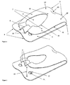
- Figures 1 and 2 show a clip comprising a lower surface 1, a curved spine 2 and an upper surface 3.
- the perimeter of the upper surface 3 comprises an outer edge 19, except where the upper surface 3 meets the spine 2.
- the lower surface 1 comprises a pair of corrugations 4 which extend around the spine 2 where they create a pair of bumps 5.
- the upper surface 3 comprises a hole 6, the perimeter of which comprises an inner edge 18, and the hole 6 separates a pair of arms 7. Behind the hole 6 is a high point 16, and behind the high point 16 is a dimple 20.
- the arms 7 meet at a nose 8.
- the nose 8 comprises a pair of crimps 9, and at the front of each crimp 9 there is a single top tooth 10 pointing towards the lower surface 1.
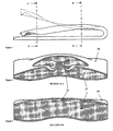
- FIGs 3 to 9 show various views of the two-bump embodiment.
- This clip is manufactured from a thin sheet of steel having two faces, which is folded over into a U-shape such that one of these faces becomes an inner face 27 and the other becomes an outer face 28.
- the inner face is shaded to distinguish it from the outer face, which is unshaded.
- Figures 1 and 2 also show that the lower surface 1 has a pair of holes 11 at the back of which a pair of bottom teeth 12 are formed, pointing towards the upper surface 3.
- Figure 23 shows the clip closed onto a thick sheaf of papers 14.
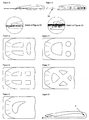
- Figure 14 shows a clip which has a hump 17
- figures 16 and 20 show clips which have an additional longitudinal strut 15
- figure 17 shows a clip which has an additional transverse bridge 21.
- the spine end of the clip is termed the 'back' and the nose end of the clip is termed the 'front'.
- the bending stresses in the clip caused by its clamping action are low in the region to the left of plane A-A, moderate between plane A-A and plane B-B, and high to the right of plane B-B.
- the present invention is stiffer than other foldover clips with planar or cylindrical spines because of the geometry in the region to the right of plane B-B.
- the curvature in the lower surface caused by the corrugations, and the curvature in the spine caused by the two bumps, and the curvature in the transition region ensure that the profile subject to the bending stresses are all considerably thicker than the thickness of the steel.
- the stiffness throughout the region to the right of.plane B-B is associated with the fact that the outer face of the lower surface, and of the spine, and of the transition region are all visible in the side-profile of the clip shown in figure 3 .
- each bump is essentially barrel-shaped.
- the shape of the material in the spine is essentially that created by sweeping the corrugated profile of the lower surface (as shown in figures 4, 5 , 7 and 8 ) around an arc. Starting from a substantially flat sheet, this shape cannot be created by two-dimensional bending alone as it requires the material to be stretched and / or compressed and / or sheared to form such a shape.
- the radius of curvature around the axis of the spine therefore varies along the length of the spine, such that it is greater at the centre of each bump (where material has been stretched) and is less between and outside the bumps (where the material may have been compressed).
- the stretching and compression can be understood by considering the length of the arc through which the corrugated profile of the lower surface has been swept, which is longer near the centre of each bump, and shorter between and outside the bumps.
- the clip When the clip is in the open position (as shown in figure 2 ), its mouth 13 is open wide enough to accept a generous sheaf of papers 14.
- the outer edge 19 of the upper surface 3 is in tension and makes the outer face 28 of the upper surface 3 substantially concave as shown in figures 7 and 8 .
- the clip can easily be placed around the papers 14 until the edge of the papers 14 reaches the spine 2 which acts as an end-stop for the papers 14.
- the clip can then be closed onto the papers 14 simply by pressing on the nose 8 of the clip. This pressure causes the clip to toggle from its stable open position into its stable closed position, as shown in figure 1 .
- the clamping force generated between the nose 8 and the lower surface 1 depends on many factors, but because the clip acts as a spring the clamping force depends on the thickness of the sheaf of papers being clamped. If the sheaf is thick (as shown in figure 23 ) the clamping force is large, but if the sheaf is thin (as shown in figure 22 ) the clamping force is less.
- the upper teeth 10 and lower teeth 12 are therefore designed to assist in retaining the papers 14 securely when the clip is used on a small sheaf of papers as shown in figure 22 .
- the upper teeth 10 and lower teeth 12 will pierce the papers 14 making the clip as secure as a staple. Often, the papers cannot be removed without tearing them.
- the upper teeth 10 and lower teeth 12 will pierce several sheets at the top of the sheaf and several sheets at the bottom of the sheaf, but the middle sheets will be held just by the clamping force of the clip. This force is sufficient to grip such papers quite securely.
- the clip can be toggled into its open position to release the papers by pressing on the high point 16 of the clip. This pressure causes the clip to toggle from its stable closed position back into its stable open position. The clip can then be removed from the papers 14.
- Preferred embodiments are made from spring steel, which may be either a carbon spring steel or a stainless spring steel.
- the material thickness is important. If the material is too thin then it will not have the strength to grip the papers strongly enough, but if the material is too thick then this will prevent the shape of the bistable upper surface changing enough before reaching its elastic limit.
- preferred embodiments of the present invention use relatively thin material, stiffened by corrugations in the lower surface and bumps in the spine. These features stiffen the material in the spine and lower surface, whilst allowing a generous amount of movement in the upper surface.
- the peened embodiment can be manufactured from 0.25mm thick high-tensile stainless steel sheet, and is about 25 mm long and 20 mm wide. These dimensions are not limiting, and in particular the clip can be reduced in size. A smaller clip might be made from thinner material.
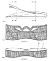
- Figures 4, 5 , 7 and 8 show the corrugations in cross-sections through the lower surface of the two-bump embodiment and figure 9 shows how the same curvature continues to form the bumps in the spine.
- the hole in the upper surface is an important feature.
- the front edge of the hole is held in tension by the crimps, but the back edge and especially the side edges are in compression, and these compression members behave as bucklable struts. This bucklability is the source of the clip's bistability.
- the upper surface of most embodiments of the present invention is a flat sheet subjected to elastic deformations, similar to hairclips. Apart from the crimping or peening, the upper surface is deformed only by elastic bending (not by stretching or shearing).
- a flat sheet can only be elastically bent into two possible shapes, a cylinder or a cone - and in the case of the present invention the upper surface is deformed into an irregular but approximately frustoconical shape, rather like a thin Belleville washer.
- This frustoconical shape makes the side profile of the upper surface considerably deeper than the thickness of the material, which therefore gives the upper surface good stiffness.
- the lower surface is stiffened by the corrugations and the spine is stiffened by the bumps, but there could still be a less stiff region around the transition between the frustoconical upper surface and the two bumps.
- the frustoconical shape of the upper surface has a highly desirable but counter-intuitive stiffening characteristic.
- this force does not have any tendency to toggle the clip. Instead, such a force increases the tension in the outer edges of the upper surface of the clip, thereby deepening the conical form, increasing the depth of the side profile of the upper surface and stiffening the structure, making it more stable in its closed position.
- the frustoconical upper surface is formed by internal stresses which arise when the nose of the clip is narrowed by the crimps 9 being created by plastic deformation of the nose 8.
- the frustoconical shape could be made by means other than crimping, but crimping has several advantages:
- Hairclips require a much larger reduction in the width of the nose, so they are usually riveted. Riveting is relatively expensive, and is also inappropriate for making small reductions in the width of the nose.
- the 25 mm x 20 mm embodiment of the present invention requires a reduction in the width of the nose of about 1 mm.
- Hairclips are also sometimes peened, with a single blow at each end of the elongated hole in the upper surface of the hairclip.
- the internal stresses which create the frustoconical shape of the present invention may also be made by peening, as shown in figure 18 .
- the arms of the clip On both sides of the hole in the upper surface are the arms of the clip.
- the arms of the clip become broader towards the back of the clip, causing the hole to become narrower.
- the best way to get the maximum shape-change from the upper surface is for the entire upper surface to be more or less uniformly deformed, being bent to a more or less constant radius of curvature, such radius being limited by the elastic limit of the material.
- Preferred embodiments of the present invention achieve this condition by making the arms wider towards the back of the clip.
- the broadening of the arms towards the back of the clip also increases the stiffness around the back of the clip, where the bending moment is greatest.
- the present invention may be manufactured with or without upper teeth, and with or without lower teeth. Without teeth, it operates purely as a paperclip and relies totally on:
- the teeth are large enough to pierce (or at least dent) several sheets of paper, as this improves the ability of the clip to hold papers securely.
- the damage caused to papers by the teeth is a disadvantage, which may be substantially overcome if the teeth are replaced by elongated flanges.
- a clip with such flanges such as that shown in figure 21 will do less damage to the papers than would be caused by teeth, but will grip the papers more securely than a clip without either teeth or flanges.
- the 'Bump Forming' process may be the most difficult of these processes, because this process requires the material to be plastically stretched and / or sheared and / or compressed.
- the other processes are simpler, as they are just bending processes.
- Plastic compression may be undesirable as it tends to make the material buckle, but plastic compression is avoidable if the clip is manufactured with one or two ridges 25 as shown in figures 11 and 12 , instead of with one or two bumps as shown in figures 9 and 10 .
- Figure 12 shows the one-ridge embodiment, which is a clip with one ridge located between a pair of substantially cylindrical sections 26.
- the cylindrical sections are made by simple bending during the 'Spine Bending' process above, and remain substantially undeformed by the subsequent 'Bump Forming' process.
- the ridge is formed by stretching the material in the ridge and shearing the material in the region between the ridge and the cylindrical sections. The tensile force required to stretch the material in this region is counterbalanced by a compressive force in the cylindrical sections, but this compressive force is distributed through the cylindrical sections in such a way that the compressive stress levels in the cylindrical sections do not exceed the elastic limit of the material, so the material does not buckle.
- the tooling may be designed so that during this process the cylindrical sections are clamped firmly between the die and a temporarily stationary part of the punch, while a moving part of the punch stretches and shears the material between the cylindrical sections to form the ridge.
- the retention of the cylindrical sections during the forming process also helps to prevent buckling during the 'Bump Forming' process.
- the two-ridge embodiment shown in figure 11 may be formed in a similar way.
- the ridge or ridges in the one-ridge or two-ridge embodiment it may also be possible to form the ridges in the spine during the corrugating operation and to retain them during the spine bending operation by bending the spine around a shaped former, in which case the bump forming operation may not be required.
- Spheroidality is the condition that arises when some of the material in the spine of the clip is bent simultaneously in two orthogonal directions. This cannot be done simply by bending - it requires the material to be stretched and / or sheared and / or compressed, and it results in a shape which cannot be 'developed' (unfolded) out onto a flat sheet.
- these stages may all be completed in a multi stage die in a progressive die machine. In this case, the unit cost of each clip can be very low.
- the present invention is not limited to the two-bump embodiment. Some further embodiments of the present invention will now be described.
- the humped embodiment shown in figure 14 , is similar to the two-bump embodiment except that region where the spine meets the upper surface is convex, forming a hump, instead of concave as a dimple.
- the smooth embodiment shown in figure 15 , is similar to the two-bump embodiment except that the region where the spine meets the upper surface is neither convex nor concave, so the convex upper surface blends smoothly with the concave region between the two bumps of the spine.
- the smooth embodiment is aesthetically pleasing because it has simpler, cleaner lines but it is harder to manufacture because there is nowhere for the extra material from between the two bumps to move to, so the material in this region has to be stretched and / or sheared more than in the dimpled and humped embodiments.
- the strut embodiment is similar to the smooth embodiment, except that there is a strut 15 perpendicular to the axis of the spine which divides the hole, so the strut embodiment has two holes.
- the strut is in compression in both the clip's stable open state and its stable closed state, and the strut therefore behaves as another bucklable member.
- the strut therefore increases the stability of the clip in both its stable positions and can also increase the amount of movement in the upper surface of the clip.
- the strut embodiment is easier to toggle from the closed to the open position than the two-bump embodiment because the user can apply pressure to the strut, instead of to the high point.
- the strut embodiment of the present invention shares several common features with WO96/21573 , which also has a central compressive strut.
- the primary tension is in the arms (acting perpendicular to the axis of the spine) whereas in the present invention the primary tension is across the nose (acting parallel to the axis of the spine), or, in the case of the peened and coned embodiments of the strut embodiment, the primary tension is around the entire perimeter of the upper surface of the clip.
- the basic mechanism of WO96/21573 is a linear compressive bucklable strut held in compression between a pair of linear tensile members, whereas the basic mechanism of preferred embodiments of the present invention is more like a Belleville Washer, in which a hoop tension around the outer edge of the upper surface of the clip is balanced by a hoop compression around (most of) the inner edge of the clip (the perimeter of the hole).
- the bridge embodiment a version of which is shown in figure 17 , is similar to the smooth embodiment, except that there is a second hole between the main hole and the spine.
- the piece of material remaining between the two holes is called the bridge.
- the bridge embodiment is easier to toggle from the closed to the open position than the two-bump embodiment because the user can apply pressure to the bridge, instead of to the high point.
- the bridge is in compression in both the clip's stable open and its stable closed state, so the bridge behaves as an additional bucklable member.
- the bridge is curved because it is in compression, and the curvature of the bridge may increase the curvature of the sides of the clip, which may further enhance the function of this embodiment.
- Three further embodiments can be made by combining the strut embodiment with the bridge embodiment to create either three or four holes in the upper surface, as shown in figures 24-26 .
- the configuration of the four holes can be changed again as shown in figure 27 .
- Each of these embodiments has different mechanical, ergonomic and aesthetic characteristics, so each of these embodiments may be chosen to satisfy different requirements.
- the peened embodiment shown in figure 18 , is similar to the two-bump embodiment except that the compressive force around the perimeter of the hole is created not by crimps creating tension along the nose, but by peening along the inner edge (around the perimeter of the hole).
- the peening reduces the thickness of the material around the perimeter of the hole, and this reduction in thickness leads to a corresponding increase in the length of the inner edge, which creates compressive forces around the inner edge and corresponding tensile forces around the outer edge.
- the peened embodiment and the coned hole embodiment are aesthetically simpier than the two-bump embodiment because they are not crimped. Also, it may be easier in high volume manufacture (eg in a progressive die machine) to peen the perimeter of the hole or to conically form then reverse form the upper surface than to crimp the nose of the clip. Furthermore, the elongated flange would be easier to implement on one of these embodiments as the elongated flange could conflict with the crimps.
- the one bump embodiment, shown in figure 20 has a spine with just one bump instead of two. This does not make the spine as stiff as when there are two bumps, but it may be easier to manufacture.
- a particular advantage of the preferred embodiments of the present invention is the fact that the clips nest together when in the open position, as shown in figure 13 . This allows a large number of clips to be held in a relatively small amount of space, and also ensures that each clip is in the same orientation as the next clip, which will prevent them tangling with each other.
Landscapes
- Clamps And Clips (AREA)
- Sheet Holders (AREA)
- Gripping Jigs, Holding Jigs, And Positioning Jigs (AREA)
- Wire Bonding (AREA)
Applications Claiming Priority (2)
| Application Number | Priority Date | Filing Date | Title |
|---|---|---|---|
| GB0414854A GB2415735A (en) | 2004-07-02 | 2004-07-02 | Bi-stable clip made from sheet material |
| PCT/GB2005/002593 WO2006003415A1 (en) | 2004-07-02 | 2005-07-01 | Clip |
Publications (2)
| Publication Number | Publication Date |
|---|---|
| EP1708883A1 EP1708883A1 (en) | 2006-10-11 |
| EP1708883B1 true EP1708883B1 (en) | 2008-05-07 |
Family
ID=32843460
Family Applications (1)
| Application Number | Title | Priority Date | Filing Date |
|---|---|---|---|
| EP05756954A Expired - Lifetime EP1708883B1 (en) | 2004-07-02 | 2005-07-01 | Clip |
Country Status (9)
| Country | Link |
|---|---|
| US (1) | US7937813B2 (enExample) |
| EP (1) | EP1708883B1 (enExample) |
| JP (1) | JP4898670B2 (enExample) |
| CN (1) | CN101005950B (enExample) |
| AT (1) | ATE394225T1 (enExample) |
| DE (1) | DE602005006525D1 (enExample) |
| ES (1) | ES2307187T3 (enExample) |
| GB (1) | GB2415735A (enExample) |
| WO (1) | WO2006003415A1 (enExample) |
Cited By (1)
| Publication number | Priority date | Publication date | Assignee | Title |
|---|---|---|---|---|
| US7937813B2 (en) | 2004-07-02 | 2011-05-10 | Innoverce Engineering Ltd. | Clip |
Families Citing this family (17)
| Publication number | Priority date | Publication date | Assignee | Title |
|---|---|---|---|---|
| USD668091S1 (en) | 2000-07-17 | 2012-10-02 | Zahner Design Group, Ltd. | Shower curtain |
| US20100078101A1 (en) * | 2008-09-26 | 2010-04-01 | Glenn Styron | Shielded Money Clip |
| GB2471332B (en) * | 2009-06-26 | 2011-05-18 | Innoverce Engineering Ltd | Clip |
| US8656521B2 (en) | 2010-07-12 | 2014-02-25 | Jb Creations Llc | Goggle lens cover |
| US8266770B2 (en) | 2010-08-18 | 2012-09-18 | Tecco, Inc. | Clip for fabrics |
| DE102011107877A1 (de) * | 2011-07-18 | 2013-01-24 | Kiekert Ag | Schloss für eine Fahrzeugtür mit Federblech im Einlaufbereich des Schließbolzens |
| US8622432B2 (en) * | 2012-01-25 | 2014-01-07 | Martin H. Bloomberg | Binding element and associated method for binding |
| US8714596B1 (en) | 2012-01-25 | 2014-05-06 | Martin H. Bloomberg | Binding element and associated method for binding |
| US9902557B2 (en) * | 2014-05-25 | 2018-02-27 | Jezekiel Ben-Arie | Clasping device for infusion bags III |
| CN106441012A (zh) * | 2016-10-31 | 2017-02-22 | 洛阳中岩工程材料有限公司 | 一种摩擦式可锁紧派尺 |
| US10918139B2 (en) * | 2017-06-06 | 2021-02-16 | Dina Sue Toth | Undergarment clip |
| USD823097S1 (en) * | 2017-09-18 | 2018-07-17 | M.G. Manufacturing Company, Inc. | Buckle for a shower curtain |
| NL2019920B1 (en) * | 2017-11-16 | 2019-05-22 | Fischer Georg Waga Nv | Coupling device |
| PL423582A1 (pl) * | 2017-11-24 | 2019-06-03 | Cezary Tkaczyk | Nowe cechy sprężynującej zapinki zatrzaskowej do łączenia elementów płaskich, arkuszy i płaskich lub mniej płaskich elementów opakowań zwłaszcza papierowych zaopatrzonych w odpowiednią perforację |
| US10699603B2 (en) * | 2018-01-10 | 2020-06-30 | Kerry Deco | Apparatus for a textile tag |
| USD859964S1 (en) * | 2018-04-27 | 2019-09-17 | M.G. Manufacturing Company, Inc. | Lateral slit buckle for a shower curtain |
| BR202023006288U2 (pt) * | 2023-04-04 | 2023-10-10 | Cravo Colucci Alexandre | Disposição construtiva introduzida em dispositivo a ser incorporado a recipientes do tipo tubo flexível |
Family Cites Families (27)
| Publication number | Priority date | Publication date | Assignee | Title |
|---|---|---|---|---|
| DE80280C (enExample) | ||||
| US616385A (en) * | 1898-12-20 | Corner-fastening for desk-pads | ||
| US2009941A (en) * | 1934-04-05 | 1935-07-30 | Hickok Mfg Co Inc | Necktie clasp |
| US3082773A (en) | 1961-09-21 | 1963-03-26 | Tip Top Products Company | Hair clip |
| US3416202A (en) | 1966-07-24 | 1968-12-17 | Sasaoka Takenori | Resilient plate clip |
| CH543400A (de) | 1972-10-10 | 1973-10-31 | Peyer Siegfried | Klemmvorrichtung für Büropapiere |
| US4011639A (en) | 1974-04-24 | 1977-03-15 | Wilson Manufacturing Corporation | Clip |
| US4397577A (en) | 1981-01-23 | 1983-08-09 | Peter Bauer | Snap-action one-piece clamping device |
| AT379298B (de) | 1982-06-09 | 1985-12-10 | Hirsch Hermann Leder Kunstst | Ein- oder mehrschichtiges band aus flexiblem werkstoff |
| JPS62147577A (ja) * | 1985-12-23 | 1987-07-01 | Tokyo Electric Co Ltd | ハンドスキヤナ |
| US4991269A (en) * | 1987-03-13 | 1991-02-12 | Akitada Kuroda | Clip |
| US4716634A (en) * | 1987-05-05 | 1988-01-05 | Fan Wen Yuan | Two-piece reinforced clothes peg |
| US4738007A (en) | 1987-07-01 | 1988-04-19 | Demarest Russell G Jun | Clip for stacked sheets |
| US4947524A (en) * | 1990-01-19 | 1990-08-14 | Chang Chin Fu | Resilient sheet-steel paper clip |
| US5113554A (en) * | 1991-04-26 | 1992-05-19 | Gallo Christine A | Clothing hanger clip |
| JP2500403B2 (ja) * | 1991-08-07 | 1996-05-29 | レック株式会社 | バネクリップ |
| DE9204429U1 (de) | 1992-04-01 | 1992-06-17 | Pusskailer, Helmut, 8710 Kitzingen | Kunststoff-Klemmschiene für blattförmiges Haltegut oder Mappen bzw. Taschen zur Aufbewahrung von solchem Gut |
| NL9500063A (nl) * | 1995-01-12 | 1996-08-01 | Markclip Int Bv | Inrichting voor het vasthouden van papier en werkwijze voor het vormen daarvan. |
| JPH106676A (ja) * | 1996-06-20 | 1998-01-13 | Hideyuki Hiraide | クリップ |
| USD392415S (en) | 1997-03-03 | 1998-03-17 | Ching Chen Liao | Hair clip |
| JP3018236B2 (ja) * | 1997-07-09 | 2000-03-13 | 株式会社ヒロモリ | 紙ばさみ |
| JPH1142878A (ja) | 1997-07-28 | 1999-02-16 | Takashi Numao | 係止具 |
| JP2000190670A (ja) * | 1998-12-28 | 2000-07-11 | Tetsumasa Kuroda | クリップ |
| CN2459188Y (zh) * | 2000-12-22 | 2001-11-14 | 神基科技股份有限公司 | 夹纸器 |
| JP3470101B2 (ja) * | 2001-01-25 | 2003-11-25 | 東京金属工業株式会社 | クリップ |
| US6418595B1 (en) * | 2001-02-13 | 2002-07-16 | Chin-Feng Shih | Clothes hanger clasp |
| GB2415735A (en) | 2004-07-02 | 2006-01-04 | Julian Claude Peck | Bi-stable clip made from sheet material |
-
2004
- 2004-07-02 GB GB0414854A patent/GB2415735A/en not_active Withdrawn
-
2005
- 2005-07-01 WO PCT/GB2005/002593 patent/WO2006003415A1/en not_active Ceased
- 2005-07-01 JP JP2007518701A patent/JP4898670B2/ja not_active Expired - Fee Related
- 2005-07-01 ES ES05756954T patent/ES2307187T3/es not_active Expired - Lifetime
- 2005-07-01 AT AT05756954T patent/ATE394225T1/de not_active IP Right Cessation
- 2005-07-01 EP EP05756954A patent/EP1708883B1/en not_active Expired - Lifetime
- 2005-07-01 CN CN200580022274.XA patent/CN101005950B/zh not_active Expired - Fee Related
- 2005-07-01 US US11/571,308 patent/US7937813B2/en not_active Expired - Fee Related
- 2005-07-01 DE DE602005006525T patent/DE602005006525D1/de not_active Expired - Lifetime
Cited By (1)
| Publication number | Priority date | Publication date | Assignee | Title |
|---|---|---|---|---|
| US7937813B2 (en) | 2004-07-02 | 2011-05-10 | Innoverce Engineering Ltd. | Clip |
Also Published As
| Publication number | Publication date |
|---|---|
| JP4898670B2 (ja) | 2012-03-21 |
| US20080072403A1 (en) | 2008-03-27 |
| CN101005950B (zh) | 2011-08-10 |
| JP2008504506A (ja) | 2008-02-14 |
| ATE394225T1 (de) | 2008-05-15 |
| ES2307187T3 (es) | 2008-11-16 |
| WO2006003415A1 (en) | 2006-01-12 |
| GB0414854D0 (en) | 2004-08-04 |
| CN101005950A (zh) | 2007-07-25 |
| US7937813B2 (en) | 2011-05-10 |
| GB2415735A (en) | 2006-01-04 |
| EP1708883A1 (en) | 2006-10-11 |
| DE602005006525D1 (de) | 2008-06-19 |
Similar Documents
| Publication | Publication Date | Title |
|---|---|---|
| EP1708883B1 (en) | Clip | |
| EP1159093B1 (en) | Method for forming a short-radius bend in flanged sheet metal member and connector produced thereby | |
| US3754303A (en) | High compression band clamp | |
| EP3828096A1 (en) | A tab to be affixed to a can end | |
| JP2001217013A (ja) | 端子金具 | |
| JP2517757B2 (ja) | 板状金属片を結合するための工具セット | |
| JP6426792B2 (ja) | ハンドル挿入式バインディングクリップ | |
| JP2005187073A (ja) | 陥凹面を設けたストラップ緊結用バックル | |
| US20070175002A1 (en) | Binder clip | |
| US5097728A (en) | Biopsy forceps jaw and method for making it | |
| EP1069050A2 (en) | Binding clip | |
| AU2010202502B2 (en) | Clip | |
| JP7719489B2 (ja) | クリップ | |
| CN1446061A (zh) | 加强支承条带上的孔边缘的孔眼扣环及将孔眼扣环装在支承条带上的装置 | |
| US20020095748A1 (en) | Clip | |
| CN100542831C (zh) | 文件装订件以及文件夹或装订夹 | |
| JP4795255B2 (ja) | 書類ファスナ並びにファイル又はフォルダ | |
| AU2004203306A1 (en) | Improved Pillar Anchor and Method for Manufacturing the Same | |
| DE19608207A1 (de) | Klammer | |
| CN2759269Y (zh) | 发夹的结构 | |
| JP3240932U (ja) | 雨水枡蓋の穴仕切りカバー | |
| JP3069763U (ja) | カシメ止め金具 | |
| NL2025023B1 (nl) | Hoekklem voor een vellenstapel | |
| JP2917854B2 (ja) | クリップ | |
| JPH10278464A (ja) | クリップ |
Legal Events
| Date | Code | Title | Description |
|---|---|---|---|
| PUAI | Public reference made under article 153(3) epc to a published international application that has entered the european phase |
Free format text: ORIGINAL CODE: 0009012 |
|
| 17P | Request for examination filed |
Effective date: 20060811 |
|
| AK | Designated contracting states |
Kind code of ref document: A1 Designated state(s): AT BE BG CH CY CZ DE DK EE ES FI FR GB GR HU IE IS IT LI LT LU LV MC NL PL PT RO SE SI SK TR |
|
| 17Q | First examination report despatched |
Effective date: 20061115 |
|
| DAX | Request for extension of the european patent (deleted) | ||
| GRAP | Despatch of communication of intention to grant a patent |
Free format text: ORIGINAL CODE: EPIDOSNIGR1 |
|
| GRAS | Grant fee paid |
Free format text: ORIGINAL CODE: EPIDOSNIGR3 |
|
| GRAA | (expected) grant |
Free format text: ORIGINAL CODE: 0009210 |
|
| AK | Designated contracting states |
Kind code of ref document: B1 Designated state(s): AT BE BG CH CY CZ DE DK EE ES FI FR GB GR HU IE IS IT LI LT LU LV MC NL PL PT RO SE SI SK TR |
|
| REG | Reference to a national code |
Ref country code: GB Ref legal event code: FG4D |
|
| REG | Reference to a national code |
Ref country code: CH Ref legal event code: EP |
|
| REG | Reference to a national code |
Ref country code: IE Ref legal event code: FG4D Free format text: LANGUAGE OF EP DOCUMENT: FRENCH |
|
| REF | Corresponds to: |
Ref document number: 602005006525 Country of ref document: DE Date of ref document: 20080619 Kind code of ref document: P |
|
| PG25 | Lapsed in a contracting state [announced via postgrant information from national office to epo] |
Ref country code: SI Free format text: LAPSE BECAUSE OF FAILURE TO SUBMIT A TRANSLATION OF THE DESCRIPTION OR TO PAY THE FEE WITHIN THE PRESCRIBED TIME-LIMIT Effective date: 20080507 |
|
| PG25 | Lapsed in a contracting state [announced via postgrant information from national office to epo] |
Ref country code: FI Free format text: LAPSE BECAUSE OF FAILURE TO SUBMIT A TRANSLATION OF THE DESCRIPTION OR TO PAY THE FEE WITHIN THE PRESCRIBED TIME-LIMIT Effective date: 20080507 |
|
| REG | Reference to a national code |
Ref country code: ES Ref legal event code: FG2A Ref document number: 2307187 Country of ref document: ES Kind code of ref document: T3 |
|
| PG25 | Lapsed in a contracting state [announced via postgrant information from national office to epo] |
Ref country code: AT Free format text: LAPSE BECAUSE OF FAILURE TO SUBMIT A TRANSLATION OF THE DESCRIPTION OR TO PAY THE FEE WITHIN THE PRESCRIBED TIME-LIMIT Effective date: 20080507 Ref country code: LV Free format text: LAPSE BECAUSE OF FAILURE TO SUBMIT A TRANSLATION OF THE DESCRIPTION OR TO PAY THE FEE WITHIN THE PRESCRIBED TIME-LIMIT Effective date: 20080507 Ref country code: PL Free format text: LAPSE BECAUSE OF FAILURE TO SUBMIT A TRANSLATION OF THE DESCRIPTION OR TO PAY THE FEE WITHIN THE PRESCRIBED TIME-LIMIT Effective date: 20080507 |
|
| PG25 | Lapsed in a contracting state [announced via postgrant information from national office to epo] |
Ref country code: IS Free format text: LAPSE BECAUSE OF FAILURE TO SUBMIT A TRANSLATION OF THE DESCRIPTION OR TO PAY THE FEE WITHIN THE PRESCRIBED TIME-LIMIT Effective date: 20080907 |
|
| PG25 | Lapsed in a contracting state [announced via postgrant information from national office to epo] |
Ref country code: CZ Free format text: LAPSE BECAUSE OF FAILURE TO SUBMIT A TRANSLATION OF THE DESCRIPTION OR TO PAY THE FEE WITHIN THE PRESCRIBED TIME-LIMIT Effective date: 20080507 Ref country code: SE Free format text: LAPSE BECAUSE OF FAILURE TO SUBMIT A TRANSLATION OF THE DESCRIPTION OR TO PAY THE FEE WITHIN THE PRESCRIBED TIME-LIMIT Effective date: 20080807 Ref country code: DK Free format text: LAPSE BECAUSE OF FAILURE TO SUBMIT A TRANSLATION OF THE DESCRIPTION OR TO PAY THE FEE WITHIN THE PRESCRIBED TIME-LIMIT Effective date: 20080507 Ref country code: LT Free format text: LAPSE BECAUSE OF FAILURE TO SUBMIT A TRANSLATION OF THE DESCRIPTION OR TO PAY THE FEE WITHIN THE PRESCRIBED TIME-LIMIT Effective date: 20080507 |
|
| PG25 | Lapsed in a contracting state [announced via postgrant information from national office to epo] |
Ref country code: PT Free format text: LAPSE BECAUSE OF FAILURE TO SUBMIT A TRANSLATION OF THE DESCRIPTION OR TO PAY THE FEE WITHIN THE PRESCRIBED TIME-LIMIT Effective date: 20081007 Ref country code: RO Free format text: LAPSE BECAUSE OF FAILURE TO SUBMIT A TRANSLATION OF THE DESCRIPTION OR TO PAY THE FEE WITHIN THE PRESCRIBED TIME-LIMIT Effective date: 20080507 Ref country code: BE Free format text: LAPSE BECAUSE OF FAILURE TO SUBMIT A TRANSLATION OF THE DESCRIPTION OR TO PAY THE FEE WITHIN THE PRESCRIBED TIME-LIMIT Effective date: 20080507 Ref country code: SK Free format text: LAPSE BECAUSE OF FAILURE TO SUBMIT A TRANSLATION OF THE DESCRIPTION OR TO PAY THE FEE WITHIN THE PRESCRIBED TIME-LIMIT Effective date: 20080507 |
|
| PLBE | No opposition filed within time limit |
Free format text: ORIGINAL CODE: 0009261 |
|
| STAA | Information on the status of an ep patent application or granted ep patent |
Free format text: STATUS: NO OPPOSITION FILED WITHIN TIME LIMIT |
|
| PG25 | Lapsed in a contracting state [announced via postgrant information from national office to epo] |
Ref country code: MC Free format text: LAPSE BECAUSE OF NON-PAYMENT OF DUE FEES Effective date: 20080731 |
|
| 26N | No opposition filed |
Effective date: 20090210 |
|
| REG | Reference to a national code |
Ref country code: IE Ref legal event code: MM4A |
|
| PG25 | Lapsed in a contracting state [announced via postgrant information from national office to epo] |
Ref country code: EE Free format text: LAPSE BECAUSE OF FAILURE TO SUBMIT A TRANSLATION OF THE DESCRIPTION OR TO PAY THE FEE WITHIN THE PRESCRIBED TIME-LIMIT Effective date: 20080507 Ref country code: BG Free format text: LAPSE BECAUSE OF FAILURE TO SUBMIT A TRANSLATION OF THE DESCRIPTION OR TO PAY THE FEE WITHIN THE PRESCRIBED TIME-LIMIT Effective date: 20080807 |
|
| PG25 | Lapsed in a contracting state [announced via postgrant information from national office to epo] |
Ref country code: IE Free format text: LAPSE BECAUSE OF NON-PAYMENT OF DUE FEES Effective date: 20080701 |
|
| REG | Reference to a national code |
Ref country code: CH Ref legal event code: PL |
|
| PG25 | Lapsed in a contracting state [announced via postgrant information from national office to epo] |
Ref country code: CH Free format text: LAPSE BECAUSE OF NON-PAYMENT OF DUE FEES Effective date: 20090731 Ref country code: LI Free format text: LAPSE BECAUSE OF NON-PAYMENT OF DUE FEES Effective date: 20090731 |
|
| PG25 | Lapsed in a contracting state [announced via postgrant information from national office to epo] |
Ref country code: CY Free format text: LAPSE BECAUSE OF FAILURE TO SUBMIT A TRANSLATION OF THE DESCRIPTION OR TO PAY THE FEE WITHIN THE PRESCRIBED TIME-LIMIT Effective date: 20080507 Ref country code: HU Free format text: LAPSE BECAUSE OF FAILURE TO SUBMIT A TRANSLATION OF THE DESCRIPTION OR TO PAY THE FEE WITHIN THE PRESCRIBED TIME-LIMIT Effective date: 20081108 Ref country code: LU Free format text: LAPSE BECAUSE OF NON-PAYMENT OF DUE FEES Effective date: 20080701 |
|
| PG25 | Lapsed in a contracting state [announced via postgrant information from national office to epo] |
Ref country code: TR Free format text: LAPSE BECAUSE OF FAILURE TO SUBMIT A TRANSLATION OF THE DESCRIPTION OR TO PAY THE FEE WITHIN THE PRESCRIBED TIME-LIMIT Effective date: 20080507 |
|
| PG25 | Lapsed in a contracting state [announced via postgrant information from national office to epo] |
Ref country code: GR Free format text: LAPSE BECAUSE OF FAILURE TO SUBMIT A TRANSLATION OF THE DESCRIPTION OR TO PAY THE FEE WITHIN THE PRESCRIBED TIME-LIMIT Effective date: 20080808 |
|
| REG | Reference to a national code |
Ref country code: FR Ref legal event code: PLFP Year of fee payment: 11 |
|
| REG | Reference to a national code |
Ref country code: DE Ref legal event code: R084 Ref document number: 602005006525 Country of ref document: DE |
|
| PGFP | Annual fee paid to national office [announced via postgrant information from national office to epo] |
Ref country code: IT Payment date: 20150703 Year of fee payment: 11 |
|
| PGFP | Annual fee paid to national office [announced via postgrant information from national office to epo] |
Ref country code: NL Payment date: 20150925 Year of fee payment: 11 |
|
| REG | Reference to a national code |
Ref country code: FR Ref legal event code: PLFP Year of fee payment: 12 |
|
| PGFP | Annual fee paid to national office [announced via postgrant information from national office to epo] |
Ref country code: FR Payment date: 20161011 Year of fee payment: 12 Ref country code: DE Payment date: 20161108 Year of fee payment: 12 Ref country code: GB Payment date: 20161011 Year of fee payment: 12 |
|
| PGFP | Annual fee paid to national office [announced via postgrant information from national office to epo] |
Ref country code: ES Payment date: 20161107 Year of fee payment: 12 |
|
| REG | Reference to a national code |
Ref country code: NL Ref legal event code: MM Effective date: 20160801 |
|
| PG25 | Lapsed in a contracting state [announced via postgrant information from national office to epo] |
Ref country code: NL Free format text: LAPSE BECAUSE OF NON-PAYMENT OF DUE FEES Effective date: 20160801 |
|
| PG25 | Lapsed in a contracting state [announced via postgrant information from national office to epo] |
Ref country code: IT Free format text: LAPSE BECAUSE OF NON-PAYMENT OF DUE FEES Effective date: 20160701 |
|
| REG | Reference to a national code |
Ref country code: DE Ref legal event code: R119 Ref document number: 602005006525 Country of ref document: DE |
|
| GBPC | Gb: european patent ceased through non-payment of renewal fee |
Effective date: 20170701 |
|
| REG | Reference to a national code |
Ref country code: FR Ref legal event code: ST Effective date: 20180330 |
|
| PG25 | Lapsed in a contracting state [announced via postgrant information from national office to epo] |
Ref country code: GB Free format text: LAPSE BECAUSE OF NON-PAYMENT OF DUE FEES Effective date: 20170701 Ref country code: DE Free format text: LAPSE BECAUSE OF NON-PAYMENT OF DUE FEES Effective date: 20180201 |
|
| PG25 | Lapsed in a contracting state [announced via postgrant information from national office to epo] |
Ref country code: FR Free format text: LAPSE BECAUSE OF NON-PAYMENT OF DUE FEES Effective date: 20170731 |
|
| REG | Reference to a national code |
Ref country code: ES Ref legal event code: FD2A Effective date: 20181107 |
|
| PG25 | Lapsed in a contracting state [announced via postgrant information from national office to epo] |
Ref country code: ES Free format text: LAPSE BECAUSE OF NON-PAYMENT OF DUE FEES Effective date: 20170702 |