EP1708883B1 - Clip - Google Patents
Clip Download PDFInfo
- Publication number
- EP1708883B1 EP1708883B1 EP05756954A EP05756954A EP1708883B1 EP 1708883 B1 EP1708883 B1 EP 1708883B1 EP 05756954 A EP05756954 A EP 05756954A EP 05756954 A EP05756954 A EP 05756954A EP 1708883 B1 EP1708883 B1 EP 1708883B1
- Authority
- EP
- European Patent Office
- Prior art keywords
- clip
- spine
- clip according
- cross
- papers
- Prior art date
- Legal status (The legal status is an assumption and is not a legal conclusion. Google has not performed a legal analysis and makes no representation as to the accuracy of the status listed.)
- Not-in-force
Links
Images


Classifications
-
- B—PERFORMING OPERATIONS; TRANSPORTING
- B42—BOOKBINDING; ALBUMS; FILES; SPECIAL PRINTED MATTER
- B42F—SHEETS TEMPORARILY ATTACHED TOGETHER; FILING APPLIANCES; FILE CARDS; INDEXING
- B42F1/00—Sheets temporarily attached together without perforating; Means therefor
- B42F1/02—Paper-clips or like fasteners
-
- Y—GENERAL TAGGING OF NEW TECHNOLOGICAL DEVELOPMENTS; GENERAL TAGGING OF CROSS-SECTIONAL TECHNOLOGIES SPANNING OVER SEVERAL SECTIONS OF THE IPC; TECHNICAL SUBJECTS COVERED BY FORMER USPC CROSS-REFERENCE ART COLLECTIONS [XRACs] AND DIGESTS
- Y10—TECHNICAL SUBJECTS COVERED BY FORMER USPC
- Y10S—TECHNICAL SUBJECTS COVERED BY FORMER USPC CROSS-REFERENCE ART COLLECTIONS [XRACs] AND DIGESTS
- Y10S24/00—Buckles, buttons, clasps
- Y10S24/08—Paper clips
- Y10S24/09—Sheet material
-
- Y—GENERAL TAGGING OF NEW TECHNOLOGICAL DEVELOPMENTS; GENERAL TAGGING OF CROSS-SECTIONAL TECHNOLOGIES SPANNING OVER SEVERAL SECTIONS OF THE IPC; TECHNICAL SUBJECTS COVERED BY FORMER USPC CROSS-REFERENCE ART COLLECTIONS [XRACs] AND DIGESTS
- Y10—TECHNICAL SUBJECTS COVERED BY FORMER USPC
- Y10T—TECHNICAL SUBJECTS COVERED BY FORMER US CLASSIFICATION
- Y10T24/00—Buckles, buttons, clasps, etc.
- Y10T24/20—Paper fastener
- Y10T24/202—Resiliently biased
- Y10T24/205—One piece
-
- Y—GENERAL TAGGING OF NEW TECHNOLOGICAL DEVELOPMENTS; GENERAL TAGGING OF CROSS-SECTIONAL TECHNOLOGIES SPANNING OVER SEVERAL SECTIONS OF THE IPC; TECHNICAL SUBJECTS COVERED BY FORMER USPC CROSS-REFERENCE ART COLLECTIONS [XRACs] AND DIGESTS
- Y10—TECHNICAL SUBJECTS COVERED BY FORMER USPC
- Y10T—TECHNICAL SUBJECTS COVERED BY FORMER US CLASSIFICATION
- Y10T24/00—Buckles, buttons, clasps, etc.
- Y10T24/20—Paper fastener
- Y10T24/209—Paper-penetrating
Definitions
- This invention relates to a bistable clip suitable for clasping or clamping together two or more items.
- This clip has numerous possible applications, and is particularly well suited to joining together sheets of paper.
- the basic bistable clip is shown in DE 80280 is neither a foldover clip nor a hairclip. It is a clip made from two pieces of sheet metal, having a flat lower surface (to be positioned beneath the pages) and an upper surface which exhibits bistability on account of a central dent.
- the clip can be closed onto the papers by pressing on the front edge, causing it to toggle from its open position to its closed position, and can then be released by pressing on the central dent, which causes the clip to toggle back into its open position.
- the paperclip described in DE 80280 does not give enough movement (between its open and closed positions) to allow the clip to be very useful.
- Most of the foldover clips mentioned above incorporate one or more holes in their bistable surface, which allows them to give more movement. Even so, the design of such clips requires a compromise in selecting the thickness of the material from which the clip is to be made.
- the clip must be made of material thin enough to allow sufficient shape change between the clip's stable open position and its stable closed position. However, it must also be made of material thick enough to provide sufficient clamping force to grip the papers, without causing the material in and around the spine to be strained beyond its elastic limit.
- the present invention seeks to improve on existing foldover clips by providing a means of overcoming this compromise, enabling a foldover clip to be manufactured from thinner material and still to provide ample clamping force to grip the papers.
- the stiffness of the clip (its resistance to opening when in use) is greatly increased because the side-profile of the clip is deeper than the thickness of the material throughout the side-profile, and most especially in and around the spine.
- a clip comprising a single piece of material folded around a bend axis extending in a first direction to form first and second members (3, 1) according to claim 1.
- first member is termed the upper surface
- second member is termed the lower surface
- At least some embodiments of the present invention can be understood as bistable clips which derive some or all of their bistability by having an inner edge which is permanently in compression and an outer edge which is permanently in tension.
- DE 80280 achieves bistability by plastic deformation of the upper surface into a dome-like structure, whereas hairclips achieve this by an elastic deformation into an irregular frustoconical shape.
- the overall performance of the clip is improved if the permanent compression in the inner edge is created by means of an elastic deformation of the majority of the upper surface, rather than by a plastic deformation of the majority of the upper surface, although this elastic deformation is created by means of localised plastic deformation(s).
- the plastic deformation around the aperture in the upper surface may be done by crimping the front edge of the clip, which creates tension across the front of the clip and around the outer edge of the upper surface, but creates compression around most of the edge of the hole in the upper surface.
- the plastic deformation around the aperture in the upper surface may be done by peening part or all of the perimeter of the aperture, which creates hoop tension around some or all of the outer edge and hoop compression around some or all of the inner edge.
- At least part of the lower surface is gently corrugated, the corrugations running in a direction substantially perpendicular to the axis of the curved spine.
- These corrugations greatly increase the rigidity of the lower surface, and are especially important close to the curved spine as this region is subject to the highest bending moments.
- the corrugations propagate around at least part of the curved spine to form one or more bumps, greatly increasing the rigidity of the curved spine.
- the upper surface comprises more than one hole.
- Such embodiments have different performance characteristics, according to the configuration of the holes in the upper surface.
- one embodiment has a pair of holes separated by a compressive strut, the axis of the compressive strut being substantially perpendicular to the axis of the curved spine.
- This compressive strut can improve the bistable performance of the clip, and also provides a convenient position on which to press to toggle the clip from its closed position to its open position, and also helps to prevent papers which are being inserted into the open clip from catching on the back edge of the hole.
- the upper surface and / or the lower surface further comprise teeth, these teeth being designed to bite into the upper and / or lower pages being clipped together.
- the teeth are not sharp but are elongated into a flange, which provides a compromise between the embodiments with teeth and those without teeth.
- the clips can be nested together so the clips take up less space and to prevent the clips tangling with each other.
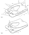
- Figures 1 and 2 show a clip comprising a lower surface 1, a curved spine 2 and an upper surface 3.
- the perimeter of the upper surface 3 comprises an outer edge 19, except where the upper surface 3 meets the spine 2.
- the lower surface 1 comprises a pair of corrugations 4 which extend around the spine 2 where they create a pair of bumps 5.
- the upper surface 3 comprises a hole 6, the perimeter of which comprises an inner edge 18, and the hole 6 separates a pair of arms 7. Behind the hole 6 is a high point 16, and behind the high point 16 is a dimple 20.
- the arms 7 meet at a nose 8.
- the nose 8 comprises a pair of crimps 9, and at the front of each crimp 9 there is a single top tooth 10 pointing towards the lower surface 1.
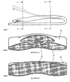
- FIGs 3 to 9 show various views of the two-bump embodiment.
- This clip is manufactured from a thin sheet of steel having two faces, which is folded over into a U-shape such that one of these faces becomes an inner face 27 and the other becomes an outer face 28.
- the inner face is shaded to distinguish it from the outer face, which is unshaded.
- Figures 1 and 2 also show that the lower surface 1 has a pair of holes 11 at the back of which a pair of bottom teeth 12 are formed, pointing towards the upper surface 3.
- Figure 23 shows the clip closed onto a thick sheaf of papers 14.
- Figure 14 shows a clip which has a hump 17
- figures 16 and 20 show clips which have an additional longitudinal strut 15
- figure 17 shows a clip which has an additional transverse bridge 21.
- the spine end of the clip is termed the 'back' and the nose end of the clip is termed the 'front'.
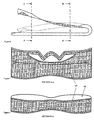
- the bending stresses in the clip caused by its clamping action are low in the region to the left of plane A-A, moderate between plane A-A and plane B-B, and high to the right of plane B-B.
- the present invention is stiffer than other foldover clips with planar or cylindrical spines because of the geometry in the region to the right of plane B-B.
- the curvature in the lower surface caused by the corrugations, and the curvature in the spine caused by the two bumps, and the curvature in the transition region ensure that the profile subject to the bending stresses are all considerably thicker than the thickness of the steel.
- the stiffness throughout the region to the right of.plane B-B is associated with the fact that the outer face of the lower surface, and of the spine, and of the transition region are all visible in the side-profile of the clip shown in figure 3 .
- each bump is essentially barrel-shaped.
- the shape of the material in the spine is essentially that created by sweeping the corrugated profile of the lower surface (as shown in figures 4, 5 , 7 and 8 ) around an arc. Starting from a substantially flat sheet, this shape cannot be created by two-dimensional bending alone as it requires the material to be stretched and / or compressed and / or sheared to form such a shape.
- the radius of curvature around the axis of the spine therefore varies along the length of the spine, such that it is greater at the centre of each bump (where material has been stretched) and is less between and outside the bumps (where the material may have been compressed).
- the stretching and compression can be understood by considering the length of the arc through which the corrugated profile of the lower surface has been swept, which is longer near the centre of each bump, and shorter between and outside the bumps.
- the clip When the clip is in the open position (as shown in figure 2 ), its mouth 13 is open wide enough to accept a generous sheaf of papers 14.
- the outer edge 19 of the upper surface 3 is in tension and makes the outer face 28 of the upper surface 3 substantially concave as shown in figures 7 and 8 .
- the clip can easily be placed around the papers 14 until the edge of the papers 14 reaches the spine 2 which acts as an end-stop for the papers 14.
- the clip can then be closed onto the papers 14 simply by pressing on the nose 8 of the clip. This pressure causes the clip to toggle from its stable open position into its stable closed position, as shown in figure 1 .
- the clamping force generated between the nose 8 and the lower surface 1 depends on many factors, but because the clip acts as a spring the clamping force depends on the thickness of the sheaf of papers being clamped. If the sheaf is thick (as shown in figure 23 ) the clamping force is large, but if the sheaf is thin (as shown in figure 22 ) the clamping force is less.
- the upper teeth 10 and lower teeth 12 are therefore designed to assist in retaining the papers 14 securely when the clip is used on a small sheaf of papers as shown in figure 22 .
- the upper teeth 10 and lower teeth 12 will pierce the papers 14 making the clip as secure as a staple. Often, the papers cannot be removed without tearing them.
- the upper teeth 10 and lower teeth 12 will pierce several sheets at the top of the sheaf and several sheets at the bottom of the sheaf, but the middle sheets will be held just by the clamping force of the clip. This force is sufficient to grip such papers quite securely.
- the clip can be toggled into its open position to release the papers by pressing on the high point 16 of the clip. This pressure causes the clip to toggle from its stable closed position back into its stable open position. The clip can then be removed from the papers 14.
- Preferred embodiments are made from spring steel, which may be either a carbon spring steel or a stainless spring steel.
- the material thickness is important. If the material is too thin then it will not have the strength to grip the papers strongly enough, but if the material is too thick then this will prevent the shape of the bistable upper surface changing enough before reaching its elastic limit.
- preferred embodiments of the present invention use relatively thin material, stiffened by corrugations in the lower surface and bumps in the spine. These features stiffen the material in the spine and lower surface, whilst allowing a generous amount of movement in the upper surface.
- the peened embodiment can be manufactured from 0.25mm thick high-tensile stainless steel sheet, and is about 25 mm long and 20 mm wide. These dimensions are not limiting, and in particular the clip can be reduced in size. A smaller clip might be made from thinner material.
- Figures 4, 5 , 7 and 8 show the corrugations in cross-sections through the lower surface of the two-bump embodiment and figure 9 shows how the same curvature continues to form the bumps in the spine.
- the hole in the upper surface is an important feature.
- the front edge of the hole is held in tension by the crimps, but the back edge and especially the side edges are in compression, and these compression members behave as bucklable struts. This bucklability is the source of the clip's bistability.
- the upper surface of most embodiments of the present invention is a flat sheet subjected to elastic deformations, similar to hairclips. Apart from the crimping or peening, the upper surface is deformed only by elastic bending (not by stretching or shearing).
- a flat sheet can only be elastically bent into two possible shapes, a cylinder or a cone - and in the case of the present invention the upper surface is deformed into an irregular but approximately frustoconical shape, rather like a thin Belleville washer.
- This frustoconical shape makes the side profile of the upper surface considerably deeper than the thickness of the material, which therefore gives the upper surface good stiffness.
- the lower surface is stiffened by the corrugations and the spine is stiffened by the bumps, but there could still be a less stiff region around the transition between the frustoconical upper surface and the two bumps.
- the frustoconical shape of the upper surface has a highly desirable but counter-intuitive stiffening characteristic.
- this force does not have any tendency to toggle the clip. Instead, such a force increases the tension in the outer edges of the upper surface of the clip, thereby deepening the conical form, increasing the depth of the side profile of the upper surface and stiffening the structure, making it more stable in its closed position.
- the frustoconical upper surface is formed by internal stresses which arise when the nose of the clip is narrowed by the crimps 9 being created by plastic deformation of the nose 8.
- the frustoconical shape could be made by means other than crimping, but crimping has several advantages:
- Hairclips require a much larger reduction in the width of the nose, so they are usually riveted. Riveting is relatively expensive, and is also inappropriate for making small reductions in the width of the nose.
- the 25 mm x 20 mm embodiment of the present invention requires a reduction in the width of the nose of about 1 mm.
- Hairclips are also sometimes peened, with a single blow at each end of the elongated hole in the upper surface of the hairclip.
- the internal stresses which create the frustoconical shape of the present invention may also be made by peening, as shown in figure 18 .
- the arms of the clip On both sides of the hole in the upper surface are the arms of the clip.
- the arms of the clip become broader towards the back of the clip, causing the hole to become narrower.
- the best way to get the maximum shape-change from the upper surface is for the entire upper surface to be more or less uniformly deformed, being bent to a more or less constant radius of curvature, such radius being limited by the elastic limit of the material.
- Preferred embodiments of the present invention achieve this condition by making the arms wider towards the back of the clip.
- the broadening of the arms towards the back of the clip also increases the stiffness around the back of the clip, where the bending moment is greatest.
- the present invention may be manufactured with or without upper teeth, and with or without lower teeth. Without teeth, it operates purely as a paperclip and relies totally on:
- the teeth are large enough to pierce (or at least dent) several sheets of paper, as this improves the ability of the clip to hold papers securely.
- the damage caused to papers by the teeth is a disadvantage, which may be substantially overcome if the teeth are replaced by elongated flanges.
- a clip with such flanges such as that shown in figure 21 will do less damage to the papers than would be caused by teeth, but will grip the papers more securely than a clip without either teeth or flanges.
- the 'Bump Forming' process may be the most difficult of these processes, because this process requires the material to be plastically stretched and / or sheared and / or compressed.
- the other processes are simpler, as they are just bending processes.
- Plastic compression may be undesirable as it tends to make the material buckle, but plastic compression is avoidable if the clip is manufactured with one or two ridges 25 as shown in figures 11 and 12 , instead of with one or two bumps as shown in figures 9 and 10 .
- Figure 12 shows the one-ridge embodiment, which is a clip with one ridge located between a pair of substantially cylindrical sections 26.
- the cylindrical sections are made by simple bending during the 'Spine Bending' process above, and remain substantially undeformed by the subsequent 'Bump Forming' process.
- the ridge is formed by stretching the material in the ridge and shearing the material in the region between the ridge and the cylindrical sections. The tensile force required to stretch the material in this region is counterbalanced by a compressive force in the cylindrical sections, but this compressive force is distributed through the cylindrical sections in such a way that the compressive stress levels in the cylindrical sections do not exceed the elastic limit of the material, so the material does not buckle.
- the tooling may be designed so that during this process the cylindrical sections are clamped firmly between the die and a temporarily stationary part of the punch, while a moving part of the punch stretches and shears the material between the cylindrical sections to form the ridge.
- the retention of the cylindrical sections during the forming process also helps to prevent buckling during the 'Bump Forming' process.
- the two-ridge embodiment shown in figure 11 may be formed in a similar way.
- the ridge or ridges in the one-ridge or two-ridge embodiment it may also be possible to form the ridges in the spine during the corrugating operation and to retain them during the spine bending operation by bending the spine around a shaped former, in which case the bump forming operation may not be required.
- Spheroidality is the condition that arises when some of the material in the spine of the clip is bent simultaneously in two orthogonal directions. This cannot be done simply by bending - it requires the material to be stretched and / or sheared and / or compressed, and it results in a shape which cannot be 'developed' (unfolded) out onto a flat sheet.
- these stages may all be completed in a multi stage die in a progressive die machine. In this case, the unit cost of each clip can be very low.
- the present invention is not limited to the two-bump embodiment. Some further embodiments of the present invention will now be described.
- the humped embodiment shown in figure 14 , is similar to the two-bump embodiment except that region where the spine meets the upper surface is convex, forming a hump, instead of concave as a dimple.
- the smooth embodiment shown in figure 15 , is similar to the two-bump embodiment except that the region where the spine meets the upper surface is neither convex nor concave, so the convex upper surface blends smoothly with the concave region between the two bumps of the spine.
- the smooth embodiment is aesthetically pleasing because it has simpler, cleaner lines but it is harder to manufacture because there is nowhere for the extra material from between the two bumps to move to, so the material in this region has to be stretched and / or sheared more than in the dimpled and humped embodiments.
- the strut embodiment is similar to the smooth embodiment, except that there is a strut 15 perpendicular to the axis of the spine which divides the hole, so the strut embodiment has two holes.
- the strut is in compression in both the clip's stable open state and its stable closed state, and the strut therefore behaves as another bucklable member.
- the strut therefore increases the stability of the clip in both its stable positions and can also increase the amount of movement in the upper surface of the clip.
- the strut embodiment is easier to toggle from the closed to the open position than the two-bump embodiment because the user can apply pressure to the strut, instead of to the high point.
- the strut embodiment of the present invention shares several common features with WO96/21573 , which also has a central compressive strut.
- the primary tension is in the arms (acting perpendicular to the axis of the spine) whereas in the present invention the primary tension is across the nose (acting parallel to the axis of the spine), or, in the case of the peened and coned embodiments of the strut embodiment, the primary tension is around the entire perimeter of the upper surface of the clip.
- the basic mechanism of WO96/21573 is a linear compressive bucklable strut held in compression between a pair of linear tensile members, whereas the basic mechanism of preferred embodiments of the present invention is more like a Belleville Washer, in which a hoop tension around the outer edge of the upper surface of the clip is balanced by a hoop compression around (most of) the inner edge of the clip (the perimeter of the hole).
- the bridge embodiment a version of which is shown in figure 17 , is similar to the smooth embodiment, except that there is a second hole between the main hole and the spine.
- the piece of material remaining between the two holes is called the bridge.
- the bridge embodiment is easier to toggle from the closed to the open position than the two-bump embodiment because the user can apply pressure to the bridge, instead of to the high point.
- the bridge is in compression in both the clip's stable open and its stable closed state, so the bridge behaves as an additional bucklable member.
- the bridge is curved because it is in compression, and the curvature of the bridge may increase the curvature of the sides of the clip, which may further enhance the function of this embodiment.
- Three further embodiments can be made by combining the strut embodiment with the bridge embodiment to create either three or four holes in the upper surface, as shown in figures 24-26 .
- the configuration of the four holes can be changed again as shown in figure 27 .
- Each of these embodiments has different mechanical, ergonomic and aesthetic characteristics, so each of these embodiments may be chosen to satisfy different requirements.
- the peened embodiment shown in figure 18 , is similar to the two-bump embodiment except that the compressive force around the perimeter of the hole is created not by crimps creating tension along the nose, but by peening along the inner edge (around the perimeter of the hole).
- the peening reduces the thickness of the material around the perimeter of the hole, and this reduction in thickness leads to a corresponding increase in the length of the inner edge, which creates compressive forces around the inner edge and corresponding tensile forces around the outer edge.
- the peened embodiment and the coned hole embodiment are aesthetically simpier than the two-bump embodiment because they are not crimped. Also, it may be easier in high volume manufacture (eg in a progressive die machine) to peen the perimeter of the hole or to conically form then reverse form the upper surface than to crimp the nose of the clip. Furthermore, the elongated flange would be easier to implement on one of these embodiments as the elongated flange could conflict with the crimps.
- the one bump embodiment, shown in figure 20 has a spine with just one bump instead of two. This does not make the spine as stiff as when there are two bumps, but it may be easier to manufacture.
- a particular advantage of the preferred embodiments of the present invention is the fact that the clips nest together when in the open position, as shown in figure 13 . This allows a large number of clips to be held in a relatively small amount of space, and also ensures that each clip is in the same orientation as the next clip, which will prevent them tangling with each other.
Abstract
Description
- This invention relates to a bistable clip suitable for clasping or clamping together two or more items. This clip has numerous possible applications, and is particularly well suited to joining together sheets of paper.
- Many different kinds of paperclip are already known in the prior art. In particular, many bistable paperclips are already known. Many of these bistable paperclips are manufactured from a single piece of sheet metal, folded over into a U-shape and the present invention is applicable to such clips, which are termed herein 'foldover clips'. The foldover area of such foldover clips is termed herein the 'spine'. Examples of foldover clips include
US5136754 ,US2002/0095748 ,US4991269 ,WO96/21573 US3898717 ,US4947524 ,JP11-042878 JP2000- 190670 US4793030 . - Probably the most commercially successful bistable clip currently on the market is not a paperclip at all but a hairclip. Hairclips do not usually incorporate such a foldover feature. Good examples are shown in
US3082773 ,US4011639 , and in Utility Patents USD392415and USD202016. Paperclips have also been designed in a similar way, without a foldover feature, such asUS43 97577 . Such devices, without any foldover feature, are termed herein 'hairclips'. - The basic bistable clip is shown in
DE 80280 is neither a foldover clip nor a hairclip. It is a clip made from two pieces of sheet metal, having a flat lower surface (to be positioned beneath the pages) and an upper surface which exhibits bistability on account of a central dent. The clip can be closed onto the papers by pressing on the front edge, causing it to toggle from its open position to its closed position, and can then be released by pressing on the central dent, which causes the clip to toggle back into its open position. - However, the paperclip described in
DE 80280 does not give enough movement (between its open and closed positions) to allow the clip to be very useful. Most of the foldover clips mentioned above incorporate one or more holes in their bistable surface, which allows them to give more movement. Even so, the design of such clips requires a compromise in selecting the thickness of the material from which the clip is to be made. The clip must be made of material thin enough to allow sufficient shape change between the clip's stable open position and its stable closed position. However, it must also be made of material thick enough to provide sufficient clamping force to grip the papers, without causing the material in and around the spine to be strained beyond its elastic limit. - These conflicting requirements create a contradiction, which necessitates a compromise. The present invention seeks to improve on existing foldover clips by providing a means of overcoming this compromise, enabling a foldover clip to be manufactured from thinner material and still to provide ample clamping force to grip the papers. In the present invention, the stiffness of the clip (its resistance to opening when in use) is greatly increased because the side-profile of the clip is deeper than the thickness of the material throughout the side-profile, and most especially in and around the spine.
- According to the present invention there is provided a clip comprising a single piece of material folded around a bend axis extending in a first direction to form first and second members (3, 1) according to claim 1.
- Herein, the first member is termed the upper surface, and the second member is termed the lower surface.
- At least some embodiments of the present invention can be understood as bistable clips which derive some or all of their bistability by having an inner edge which is permanently in compression and an outer edge which is permanently in tension.
DE 80280 achieves bistability by plastic deformation of the upper surface into a dome-like structure, whereas hairclips achieve this by an elastic deformation into an irregular frustoconical shape. The overall performance of the clip is improved if the permanent compression in the inner edge is created by means of an elastic deformation of the majority of the upper surface, rather than by a plastic deformation of the majority of the upper surface, although this elastic deformation is created by means of localised plastic deformation(s). - In this arrangement, even when the clip is in its stable open position or its stable closed position, most of the inner edge (the edge of the hole) is in compression, and the act of toggling the clip between these two stable positions increases the compression along this inner edge.
- Some objectives achieved by at least some preferred embodiments of the present invention are as follows:
- The clips should be able to hold securely any quantity of papers between a minimum of two sheets and a maximum which should be quite a thick sheaf of papers.
- The clips should be easy to remove and re-apply manually (without using any other tools), ideally with a 'push-button' modus operandi.
- The clips should have surfaces suitable for overprinting with corporate branding.
- The clips should be capable of 'nesting' together in order to:
- o prevent them from tangling;
- o reduce the space they take up.
- The clips should have a fairly low profile on the papers, without adding too much thickness to the sheaf of papers being secured.
- The clips should be manufacturable at very low cost, in very high volumes.
- The clips should be re-usable.
- In some preferred embodiments, the plastic deformation around the aperture in the upper surface may be done by crimping the front edge of the clip, which creates tension across the front of the clip and around the outer edge of the upper surface, but creates compression around most of the edge of the hole in the upper surface.
- In other preferred embodiments, the plastic deformation around the aperture in the upper surface may be done by peening part or all of the perimeter of the aperture, which creates hoop tension around some or all of the outer edge and hoop compression around some or all of the inner edge.
- In preferred embodiments, at least part of the lower surface is gently corrugated, the corrugations running in a direction substantially perpendicular to the axis of the curved spine. These corrugations greatly increase the rigidity of the lower surface, and are especially important close to the curved spine as this region is subject to the highest bending moments.
- In preferred embodiments, the corrugations propagate around at least part of the curved spine to form one or more bumps, greatly increasing the rigidity of the curved spine.
- In some preferred embodiments, the upper surface comprises more than one hole. Such embodiments have different performance characteristics, according to the configuration of the holes in the upper surface. For example, one embodiment has a pair of holes separated by a compressive strut, the axis of the compressive strut being substantially perpendicular to the axis of the curved spine. This compressive strut can improve the bistable performance of the clip, and also provides a convenient position on which to press to toggle the clip from its closed position to its open position, and also helps to prevent papers which are being inserted into the open clip from catching on the back edge of the hole.
- In some preferred embodiments, the upper surface and / or the lower surface further comprise teeth, these teeth being designed to bite into the upper and / or lower pages being clipped together. In some embodiments, the teeth are not sharp but are elongated into a flange, which provides a compromise between the embodiments with teeth and those without teeth.
- In preferred embodiments, the clips can be nested together so the clips take up less space and to prevent the clips tangling with each other.
- It will be appreciated therefore that embodiments of the present invention have advantages over conventional ('gem' type) paperclips, and also over conventional foldover clips. These and other features of the invention will be better understood from the following description of the two-bump embodiment which is given by way of example and with reference to the accompanying drawings in which:
-
Figure 1 shows a perspective view of the two-bump embodiment, in the closed position. -
Figure 2 shows a perspective view of the two-bump embodiment, in the open position. -
Figure 3 shows a side view of the two-bump embodiment, in the closed position. -
Figure 4 shows a first section through the two-bump embodiment, in the closed position. -
Figure 5 shows a second section through the two-bump embodiment, in the closed position. -
Figure 6 shows a side view of the two-bump embodiment, in the open position. -
Figure 7 shows a first section through the two-bump embodiment, in the closed position. -
Figure 8 shows a second section through the two-bump embodiment, in the closed position. -
Figure 9 shows a plan view of the two-bump embodiment, in the closed position. -
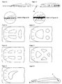
Figure 10 shows a plan view of the one-bump embodiment, in the closed position. -
Figure 11 shows a plan view of the two-ridge embodiment, in the closed position. -
Figure 12 shows a plan view of the one-ridge embodiment, in the closed position. -
Figure 13 shows a perspective view of several clips according to the smooth embodiment, in the open position, nested together. -
Figure 14 shows a perspective view of the humped embodiment, in the closed position. -
Figure 15 shows a perspective view of the smooth embodiment, in the closed position. -
Figure 16 shows a perspective view of the strut embodiment, in the closed position. -
Figure 17 shows a perspective view of the bridge embodiment, in the closed position. -
Figure 18 shows a perspective view of the peened embodiment, in the closed position. -
Figure 19 shows a perspective view of the coned embodiment, in the closed position. -
Figure 20 shows a perspective view of the one-bump embodiment, in the closed position. -
Figure 21 shows a perspective view of the flanged embodiment, in the closed position. -
Figure 22 shows a side view of the two-bump embodiment, closed onto a small number of papers, showing how the teeth grip the papers. -
Figure 23 shows a side view of the two-bump embodiment, closed onto a thick sheaf of papers, showing how the increased clamping force grips the papers. -
Figure 24 shows a plan view of a three-hole embodiment. -
Figure 25 shows a plan view of another three-hole embodiment. -
Figure 26 shows a plan view of a four-hole embodiment. -
Figure 27 shows a plan view of another four-hole embodiment. -
Figure 28 shows a plan view of an asymmetric embodiment. -
Figure 29 shows a side view of an embodiment with a spine which does not have a circular profile. - The two-bump embodiment of the present invention will now be described by reference to the accompanying figures.
-
Figures 1 and 2 show a clip comprising a lower surface 1, acurved spine 2 and an upper surface 3. The perimeter of the upper surface 3 comprises anouter edge 19, except where the upper surface 3 meets thespine 2. The lower surface 1 comprises a pair ofcorrugations 4 which extend around thespine 2 where they create a pair ofbumps 5. The upper surface 3 comprises ahole 6, the perimeter of which comprises aninner edge 18, and thehole 6 separates a pair ofarms 7. Behind thehole 6 is ahigh point 16, and behind thehigh point 16 is adimple 20. At the front of thehole 6, thearms 7 meet at anose 8. Thenose 8 comprises a pair ofcrimps 9, and at the front of eachcrimp 9 there is a singletop tooth 10 pointing towards the lower surface 1. Towards the back of the upper surface 3, there is atransition region 22 where the curvature is in transition between the double-bump profile of thespine 2 and the approximately frustoconical bistable region of the upper surface 3. -
Figures 3 to 9 show various views of the two-bump embodiment. This clip is manufactured from a thin sheet of steel having two faces, which is folded over into a U-shape such that one of these faces becomes aninner face 27 and the other becomes anouter face 28. Infigures 3 to 8 , the inner face is shaded to distinguish it from the outer face, which is unshaded. -
Figures 1 and 2 also show that the lower surface 1 has a pair ofholes 11 at the back of which a pair ofbottom teeth 12 are formed, pointing towards the upper surface 3. - When the clip is in the open position it has an
open mouth 13.Figure 23 shows the clip closed onto a thick sheaf ofpapers 14.Figure 14 shows a clip which has ahump 17,figures 16 and 20 show clips which have an additionallongitudinal strut 15, andfigure 17 shows a clip which has an additionaltransverse bridge 21. - Herein the spine end of the clip is termed the 'back' and the nose end of the clip is termed the 'front'.
- Referring to
figure 3 , the bending stresses in the clip caused by its clamping action are low in the region to the left of plane A-A, moderate between plane A-A and plane B-B, and high to the right of plane B-B. For a given thickness of steel, the present invention is stiffer than other foldover clips with planar or cylindrical spines because of the geometry in the region to the right of plane B-B. In this region, the curvature in the lower surface caused by the corrugations, and the curvature in the spine caused by the two bumps, and the curvature in the transition region, ensure that the profile subject to the bending stresses are all considerably thicker than the thickness of the steel. The stiffness throughout the region to the right of.plane B-B is associated with the fact that the outer face of the lower surface, and of the spine, and of the transition region are all visible in the side-profile of the clip shown infigure 3 . - In the two-bump embodiment, each bump is essentially barrel-shaped. The shape of the material in the spine is essentially that created by sweeping the corrugated profile of the lower surface (as shown in
figures 4, 5 ,7 and 8 ) around an arc. Starting from a substantially flat sheet, this shape cannot be created by two-dimensional bending alone as it requires the material to be stretched and / or compressed and / or sheared to form such a shape. The radius of curvature around the axis of the spine therefore varies along the length of the spine, such that it is greater at the centre of each bump (where material has been stretched) and is less between and outside the bumps (where the material may have been compressed). The stretching and compression can be understood by considering the length of the arc through which the corrugated profile of the lower surface has been swept, which is longer near the centre of each bump, and shorter between and outside the bumps. -
Figure 29 shows a side view of an embodiment with a spine which does not have a circular profile. The three-dimensional shape of the spine in this embodiment is essentially that created by sweeping the corrugated profile of the lower surface along a curve which is not an arc. The present invention is not limited to clips wherein the shape of any section through the spine would be an arc of a circle. - The operation of the two-bump embodiment will now be described by reference to the figures.
- When the clip is in the open position (as shown in
figure 2 ), itsmouth 13 is open wide enough to accept a generous sheaf ofpapers 14. Theouter edge 19 of the upper surface 3 is in tension and makes theouter face 28 of the upper surface 3 substantially concave as shown infigures 7 and 8 . The clip can easily be placed around thepapers 14 until the edge of thepapers 14 reaches thespine 2 which acts as an end-stop for thepapers 14. The clip can then be closed onto thepapers 14 simply by pressing on thenose 8 of the clip. This pressure causes the clip to toggle from its stable open position into its stable closed position, as shown infigure 1 . - When the clip is in its closed position (as shown in
figure 1 ), theouter edge 19 of the upper surface 3 is in tension and makes theouter face 28 of the upper surface 3 substantially convex as shown infigures 4 and 5 . - The clamping force generated between the
nose 8 and the lower surface 1 depends on many factors, but because the clip acts as a spring the clamping force depends on the thickness of the sheaf of papers being clamped. If the sheaf is thick (as shown infigure 23 ) the clamping force is large, but if the sheaf is thin (as shown infigure 22 ) the clamping force is less. - The
upper teeth 10 andlower teeth 12 are therefore designed to assist in retaining thepapers 14 securely when the clip is used on a small sheaf of papers as shown infigure 22 . Theupper teeth 10 andlower teeth 12 will pierce thepapers 14 making the clip as secure as a staple. Often, the papers cannot be removed without tearing them. - On a larger sheaf of papers, the
upper teeth 10 andlower teeth 12 will pierce several sheets at the top of the sheaf and several sheets at the bottom of the sheaf, but the middle sheets will be held just by the clamping force of the clip. This force is sufficient to grip such papers quite securely. - Now that the clip is in a closed position as shown in
figure 1 , it can be toggled into its open position to release the papers by pressing on thehigh point 16 of the clip. This pressure causes the clip to toggle from its stable closed position back into its stable open position. The clip can then be removed from thepapers 14. - It is important to understand how the clip is designed to exhibit the behaviour described above.
- An important aspect of the design of the present invention is selecting appropriate material of appropriate thickness. Preferred embodiments are made from spring steel, which may be either a carbon spring steel or a stainless spring steel.
- The material thickness is important. If the material is too thin then it will not have the strength to grip the papers strongly enough, but if the material is too thick then this will prevent the shape of the bistable upper surface changing enough before reaching its elastic limit.
- It is for this reason that preferred embodiments of the present invention use relatively thin material, stiffened by corrugations in the lower surface and bumps in the spine. These features stiffen the material in the spine and lower surface, whilst allowing a generous amount of movement in the upper surface.
- For example, the peened embodiment can be manufactured from 0.25mm thick high-tensile stainless steel sheet, and is about 25 mm long and 20 mm wide. These dimensions are not limiting, and in particular the clip can be reduced in size. A smaller clip might be made from thinner material.
- It is easy to corrugate the lower surface as this is a simple bending operation, but it is difficult to put bumps into the spine because this requires the material to be stretched and / or sheared and / or buckled. Some techniques for making these bumps and for avoiding buckling will be described later.
- The lower surface and spine can be stiffened by one corrugation / bump, but this is less effective than stiffening them with two corrugations / bumps. The reason for this is that the spine with one bump is surprisingly flexible. The bump comprises material curved spheroidally in two orthogonal directions (around the axis of the spine, and also to form the corrugation) and the curvature can be transferred between these two directions. This means that the clip's clamping force is low, because it can open easily by transferring the curvature about the axis of the hinge into a deeper bump. The clip with two bumps is much stiffer because there is much more resistance to this complex mode of elastic deformation.
-
Figures 4, 5 ,7 and 8 show the corrugations in cross-sections through the lower surface of the two-bump embodiment andfigure 9 shows how the same curvature continues to form the bumps in the spine. - The hole in the upper surface is an important feature. The front edge of the hole is held in tension by the crimps, but the back edge and especially the side edges are in compression, and these compression members behave as bucklable struts. This bucklability is the source of the clip's bistability.
- Unlike the plastically deformed dome structure described in
DE 80280 which requires the material to be stretched to form the dome, the upper surface of most embodiments of the present invention is a flat sheet subjected to elastic deformations, similar to hairclips. Apart from the crimping or peening, the upper surface is deformed only by elastic bending (not by stretching or shearing). A flat sheet can only be elastically bent into two possible shapes, a cylinder or a cone - and in the case of the present invention the upper surface is deformed into an irregular but approximately frustoconical shape, rather like a thin Belleville washer. - This frustoconical shape makes the side profile of the upper surface considerably deeper than the thickness of the material, which therefore gives the upper surface good stiffness. The lower surface is stiffened by the corrugations and the spine is stiffened by the bumps, but there could still be a less stiff region around the transition between the frustoconical upper surface and the two bumps. In some preferred embodiments, there is either a central dimple or a central hump behind the high point which helps to prevent there being any transitional weak section between the upper surface and the spine. This dimple or hump also makes the clip easier to manufacture, for reasons described later.
- In preferred embodiments of the present invention, the frustoconical shape of the upper surface has a highly desirable but counter-intuitive stiffening characteristic. When the clip is in the closed position and a force is applied to the upper teeth, this force does not have any tendency to toggle the clip. Instead, such a force increases the tension in the outer edges of the upper surface of the clip, thereby deepening the conical form, increasing the depth of the side profile of the upper surface and stiffening the structure, making it more stable in its closed position.
- In the crimped embodiments (all except the peened and coned embodiments), the frustoconical upper surface is formed by internal stresses which arise when the nose of the clip is narrowed by the
crimps 9 being created by plastic deformation of thenose 8. The frustoconical shape could be made by means other than crimping, but crimping has several advantages: - It is relatively easy to do and requires no additional components
- It creates useful places to position the upper teeth
- It allows the bistability of the clip to be biased towards either the open or (more desirably) the closed position
- It ensures that the force on the upper surface from the sheaf of papers acts at the correct point to ensure the effectiveness of the desirable but counter-intuitive stiffening characteristic described above
- It is relatively easy to create a relatively small amount of plastic deformation.
- Hairclips require a much larger reduction in the width of the nose, so they are usually riveted. Riveting is relatively expensive, and is also inappropriate for making small reductions in the width of the nose. The 25 mm x 20 mm embodiment of the present invention requires a reduction in the width of the nose of about 1 mm.
- Hairclips are also sometimes peened, with a single blow at each end of the elongated hole in the upper surface of the hairclip. The internal stresses which create the frustoconical shape of the present invention may also be made by peening, as shown in
figure 18 . - On both sides of the hole in the upper surface are the arms of the clip. In preferred embodiments, the arms of the clip become broader towards the back of the clip, causing the hole to become narrower. The best way to get the maximum shape-change from the upper surface is for the entire upper surface to be more or less uniformly deformed, being bent to a more or less constant radius of curvature, such radius being limited by the elastic limit of the material.
- Preferred embodiments of the present invention achieve this condition by making the arms wider towards the back of the clip. The broadening of the arms towards the back of the clip also increases the stiffness around the back of the clip, where the bending moment is greatest.
- The present invention may be manufactured with or without upper teeth, and with or without lower teeth. Without teeth, it operates purely as a paperclip and relies totally on:
- the clamping force between the upper and lower surfaces;
- friction between the papers and the clip;
- friction between one sheet of paper and the next.
- There is, in general, more friction between one sheet of paper and the next than between papers and the clip. The ability of the clip to hold papers securely is therefore greatly enhanced by teeth, even if these teeth are so small that they only penetrate one sheet of paper.
- In some embodiments, the teeth are large enough to pierce (or at least dent) several sheets of paper, as this improves the ability of the clip to hold papers securely.
- The damage caused to papers by the teeth is a disadvantage, which may be substantially overcome if the teeth are replaced by elongated flanges. A clip with such flanges such as that shown in
figure 21 will do less damage to the papers than would be caused by teeth, but will grip the papers more securely than a clip without either teeth or flanges. - Whilst the design of the clip may look quite simple, it can be difficult to manufacture the bumps in the spine. One way to make the two-bump embodiment of the present invention is as follows.
- 1. Blanking. The two-dimensional developed shape is pressed out from sheet steel.
- 2. Pre-curving. This is an optional initial plastic deformation designed to impart some residual stresses into the steel. The two-dimensional blank is gently curved along its length (perpendicular to the spine).
- 3. Corrugating. The corrugations in the lower surface are made by plastic deformation along about half the length of the blank.
- 4. Spine Bending. The spine is bent plastically around either a cylindrical former (a diameter of about 3mm is appropriate), or a former which is shaped so as to form the two bumps. In either case, the Spine Bending process removes some of the pre-curve and bumps from the spine area, but will leave some residual stresses from these earlier plastic deformations. The spine should be bent to about 180 degrees, but springback will leave a final angle of about 150 degrees at this stage.
- 5. Bump Forming. The two bumps are re-formed in the spine using a progressive series of punches and dies. This operation requires the steel to be sheared, stretched and compressed to form the correct shape. This operation causes the material to buckle where it is in compression and is therefore best done using a progressive series of punches and dies to keep control of the buckling. The first punch and die pair will have a spine which is almost cylindrical in form (with just very shallow bumps), then each punch and die pair will have progressively more curvature until the final pair finish forming the bumps. The hump or dimple is formed at the same time as the bumps, and in either case provides somewhere for the excess material from between the bumps to move to.
- 6. Crimping. The crimps are formed in the nose of the clip using appropriately shaped punches and dies. This may have to be done in several stages to avoid stretching the material while forming the crimps. The material may tend to stretch if there is too much friction between the clip and the tooling. The clip should ideally be crimped into an open position, as otherwise it will have to be toggled before the next operation.
- 7. Tooth forming. The material is bent locally to form the teeth.
- 8. Biasing. The clip should ideally be very stable when closed, but only slightly stable when open. The bias can be adjusted at this stage by subtle plastic deformations of the crimps or other parts of the upper surface.
- 9. Spine squeezing. At this stage, the clip may still be wide open due to the springback from the spine bending, although the exact angle may have been affected by subsequent operations. The final stage is therefore to squeeze the spine of the clip to the correct angle. This is best done with the clip toggled into its open position.
- In some circumstances, the sequence of these stages may be altered to suit manufacturing requirements.
- The 'Bump Forming' process may be the most difficult of these processes, because this process requires the material to be plastically stretched and / or sheared and / or compressed. The other processes are simpler, as they are just bending processes. Plastic compression may be undesirable as it tends to make the material buckle, but plastic compression is avoidable if the clip is manufactured with one or two
ridges 25 as shown infigures 11 and 12 , instead of with one or two bumps as shown infigures 9 and 10 . -
Figure 12 shows the one-ridge embodiment, which is a clip with one ridge located between a pair of substantiallycylindrical sections 26. The cylindrical sections are made by simple bending during the 'Spine Bending' process above, and remain substantially undeformed by the subsequent 'Bump Forming' process. During the 'Bump Forming' process for the one-ridge embodiment, the ridge is formed by stretching the material in the ridge and shearing the material in the region between the ridge and the cylindrical sections. The tensile force required to stretch the material in this region is counterbalanced by a compressive force in the cylindrical sections, but this compressive force is distributed through the cylindrical sections in such a way that the compressive stress levels in the cylindrical sections do not exceed the elastic limit of the material, so the material does not buckle. Furthermore, because the cylindrical sections are not being deformed during the 'Bump Forming' process, the tooling may be designed so that during this process the cylindrical sections are clamped firmly between the die and a temporarily stationary part of the punch, while a moving part of the punch stretches and shears the material between the cylindrical sections to form the ridge. The retention of the cylindrical sections during the forming process also helps to prevent buckling during the 'Bump Forming' process. The two-ridge embodiment shown infigure 11 may be formed in a similar way. - Depending on the geometry of the ridge or ridges in the one-ridge or two-ridge embodiment, it may also be possible to form the ridges in the spine during the corrugating operation and to retain them during the spine bending operation by bending the spine around a shaped former, in which case the bump forming operation may not be required.
- It is not possible to achieve the full benefit of the present invention without creating some 'spheroidality' in the spine of the clip. Spheroidality is the condition that arises when some of the material in the spine of the clip is bent simultaneously in two orthogonal directions. This cannot be done simply by bending - it requires the material to be stretched and / or sheared and / or compressed, and it results in a shape which cannot be 'developed' (unfolded) out onto a flat sheet.
- In high volume manufacture, these stages may all be completed in a multi stage die in a progressive die machine. In this case, the unit cost of each clip can be very low.
- The present invention is not limited to the two-bump embodiment. Some further embodiments of the present invention will now be described.
- The humped embodiment, shown in
figure 14 , is similar to the two-bump embodiment except that region where the spine meets the upper surface is convex, forming a hump, instead of concave as a dimple. - The smooth embodiment, shown in
figure 15 , is similar to the two-bump embodiment except that the region where the spine meets the upper surface is neither convex nor concave, so the convex upper surface blends smoothly with the concave region between the two bumps of the spine. The smooth embodiment is aesthetically pleasing because it has simpler, cleaner lines but it is harder to manufacture because there is nowhere for the extra material from between the two bumps to move to, so the material in this region has to be stretched and / or sheared more than in the dimpled and humped embodiments. - The strut embodiment, versions of which are shown in
figures 16 and 20 , is similar to the smooth embodiment, except that there is astrut 15 perpendicular to the axis of the spine which divides the hole, so the strut embodiment has two holes. The strut is in compression in both the clip's stable open state and its stable closed state, and the strut therefore behaves as another bucklable member. The strut therefore increases the stability of the clip in both its stable positions and can also increase the amount of movement in the upper surface of the clip. - The strut embodiment is easier to toggle from the closed to the open position than the two-bump embodiment because the user can apply pressure to the strut, instead of to the high point.
- In preferred versions of the strut embodiment, there is a gap between the two crimps where the strut meets the nose.
- The strut embodiment of the present invention shares several common features with
WO96/21573 WO96/21573 - The basic mechanism of
WO96/21573 - The bridge embodiment, a version of which is shown in
figure 17 , is similar to the smooth embodiment, except that there is a second hole between the main hole and the spine. The piece of material remaining between the two holes is called the bridge. As with the strut embodiment, the bridge embodiment is easier to toggle from the closed to the open position than the two-bump embodiment because the user can apply pressure to the bridge, instead of to the high point. - Also as with the strut embodiment, the bridge is in compression in both the clip's stable open and its stable closed state, so the bridge behaves as an additional bucklable member. The bridge is curved because it is in compression, and the curvature of the bridge may increase the curvature of the sides of the clip, which may further enhance the function of this embodiment.
- Three further embodiments can be made by combining the strut embodiment with the bridge embodiment to create either three or four holes in the upper surface, as shown in
figures 24-26 . The configuration of the four holes can be changed again as shown infigure 27 . Each of these embodiments has different mechanical, ergonomic and aesthetic characteristics, so each of these embodiments may be chosen to satisfy different requirements. - The aforementioned embodiments are all substantially symmetrical, but there may be advantages to asymmetric embodiments, one example of which is shown in
figure 29 . - The peened embodiment, shown in
figure 18 , is similar to the two-bump embodiment except that the compressive force around the perimeter of the hole is created not by crimps creating tension along the nose, but by peening along the inner edge (around the perimeter of the hole). The peening reduces the thickness of the material around the perimeter of the hole, and this reduction in thickness leads to a corresponding increase in the length of the inner edge, which creates compressive forces around the inner edge and corresponding tensile forces around the outer edge. - The coned hole embodiment, shown in
figure 19 , is similar to the peened embodiment in that the nose of the clip does not need to be crimped. In the coned hole embodiment, compressive forces around the perimeter of the hole are generated by plastically deforming the upper surface into the shape of a shallow cone, then reverse forming the upper surface to create a shallow cone in the opposite direction. This second (reverse) forming gives control over the residual stresses in the upper surface of the clip. - The peened embodiment and the coned hole embodiment are aesthetically simpier than the two-bump embodiment because they are not crimped. Also, it may be easier in high volume manufacture (eg in a progressive die machine) to peen the perimeter of the hole or to conically form then reverse form the upper surface than to crimp the nose of the clip. Furthermore, the elongated flange would be easier to implement on one of these embodiments as the elongated flange could conflict with the crimps.
- The one bump embodiment, shown in
figure 20 , has a spine with just one bump instead of two. This does not make the spine as stiff as when there are two bumps, but it may be easier to manufacture. - A particular advantage of the preferred embodiments of the present invention is the fact that the clips nest together when in the open position, as shown in
figure 13 . This allows a large number of clips to be held in a relatively small amount of space, and also ensures that each clip is in the same orientation as the next clip, which will prevent them tangling with each other. - It will be understood from the description above and the figures that the embodiments described do not constitute the only feasible embodiments of the present invention, as the features described may be combined together in many different ways. For example, for any given clip with two bumps in the spine and just one hole in the upper surface:
- 1. The region where the spine meets the upper surface may be smooth, or may be dimpled, or may be humped;
- 2. The plastic deformation of the upper surface required to create the bistability of the upper surface may be achieved either by crimping the nose, or by peening the inner edge(s), or by coning and reverse-coning the hole;
- 3. The clip may either have, or not have, upper teeth and / or lower teeth, and / or upper and /or lower flanges;
- Most of these variants would also be feasible with just one bump in the spine, or with one or two ridges in the spine, and / or with two or more holes in the upper surface as shown in the
figures 9-12 ,20 and24-28 . They would also be feasible with spines which do not have a circular profile, as shown infigure 29 . - It will be further understood that the present invention is potentially applicable to many different kinds of foldover clips, including but not limited to those described in the patents and patent applications referenced herein.
Claims (10)
- A clip comprising a single piece of material folded around a bend axis extending in a first direction to form a fold (2) and first and second members (3, 1), said clip arranged to receive an item or items to be held between said first and second members (3, 1), said first member (3) having an aperture (6) therein with at least some of the material around said aperture (6) being plastically deformed whereby said first member (3) has a first position of stability in which at least the free end (8) of said first member (3) has a generally convex shape and a second position of stability in which at least the free end (8) of said first member (3) has a generally concave shape, in which said fold (2) comprises a first cross-section orthogonal to said first direction and a second cross-section parallel to said first cross-section and displaced in said first direction from said first cross-section, characterised in that said first cross-section has a greater radius of curvature about axes parallel to said first direction than the radius of curvature about said axes of said second cross-section.
- A clip according to claim 1 in which said fold comprises two second cross sections, each either side of said first cross section.
- A clip according to any preceding claim in which said plastic deformation is in the form of one or more crimps (9) or one or more further bends of a portion of said material around said aperture (6).
- A clip according to claim 3 in which said one or more crimps (9) or one or more further bends are at the opposite side of said aperture (6) form the position of said first mentioned fold (2).
- A clip according to any of claims 1 to 4 in which said plastic deformation comprises thinning and/or stretching of said material at the periphery of said aperture (6).
- A clip according to any preceding claim in which said first member (3) comprises a plurality of apertures (6).
- A clip according to any preceding claim, wherein said second member (1) is provided with corrugations (4) running in a direction substantially perpendicular to said bend axis.
- A clip according to claim 7, wherein said corrugations (4) extend around at least part of said fold (2) to create bumps (5).
- A clip according to any preceding claim in which said sheet material is sheet metal.
- A clip according to any preceding claim further comprising one or more teeth (10, 12) formed on one or both of said first and second members (3,1).
Applications Claiming Priority (2)
| Application Number | Priority Date | Filing Date | Title |
|---|---|---|---|
| GB0414854A GB2415735A (en) | 2004-07-02 | 2004-07-02 | Bi-stable clip made from sheet material |
| PCT/GB2005/002593 WO2006003415A1 (en) | 2004-07-02 | 2005-07-01 | Clip |
Publications (2)
| Publication Number | Publication Date |
|---|---|
| EP1708883A1 EP1708883A1 (en) | 2006-10-11 |
| EP1708883B1 true EP1708883B1 (en) | 2008-05-07 |
Family
ID=32843460
Family Applications (1)
| Application Number | Title | Priority Date | Filing Date |
|---|---|---|---|
| EP05756954A Not-in-force EP1708883B1 (en) | 2004-07-02 | 2005-07-01 | Clip |
Country Status (9)
| Country | Link |
|---|---|
| US (1) | US7937813B2 (en) |
| EP (1) | EP1708883B1 (en) |
| JP (1) | JP4898670B2 (en) |
| CN (1) | CN101005950B (en) |
| AT (1) | ATE394225T1 (en) |
| DE (1) | DE602005006525D1 (en) |
| ES (1) | ES2307187T3 (en) |
| GB (1) | GB2415735A (en) |
| WO (1) | WO2006003415A1 (en) |
Cited By (1)
| Publication number | Priority date | Publication date | Assignee | Title |
|---|---|---|---|---|
| US7937813B2 (en) | 2004-07-02 | 2011-05-10 | Innoverce Engineering Ltd. | Clip |
Families Citing this family (16)
| Publication number | Priority date | Publication date | Assignee | Title |
|---|---|---|---|---|
| USD668091S1 (en) * | 2000-07-17 | 2012-10-02 | Zahner Design Group, Ltd. | Shower curtain |
| US20100078101A1 (en) * | 2008-09-26 | 2010-04-01 | Glenn Styron | Shielded Money Clip |
| GB2471332B (en) * | 2009-06-26 | 2011-05-18 | Innoverce Engineering Ltd | Clip |
| US8656521B2 (en) | 2010-07-12 | 2014-02-25 | Jb Creations Llc | Goggle lens cover |
| US8266770B2 (en) | 2010-08-18 | 2012-09-18 | Tecco, Inc. | Clip for fabrics |
| DE102011107877A1 (en) * | 2011-07-18 | 2013-01-24 | Kiekert Ag | Lock for a vehicle door with spring plate in the inlet area of the locking bolt |
| US8622432B2 (en) * | 2012-01-25 | 2014-01-07 | Martin H. Bloomberg | Binding element and associated method for binding |
| US8714596B1 (en) | 2012-01-25 | 2014-05-06 | Martin H. Bloomberg | Binding element and associated method for binding |
| US9902557B2 (en) * | 2014-05-25 | 2018-02-27 | Jezekiel Ben-Arie | Clasping device for infusion bags III |
| CN106441012A (en) * | 2016-10-31 | 2017-02-22 | 洛阳中岩工程材料有限公司 | Friction type lockable pi ruler |
| US10918139B2 (en) * | 2017-06-06 | 2021-02-16 | Dina Sue Toth | Undergarment clip |
| USD823097S1 (en) * | 2017-09-18 | 2018-07-17 | M.G. Manufacturing Company, Inc. | Buckle for a shower curtain |
| NL2019920B1 (en) * | 2017-11-16 | 2019-05-22 | Fischer Georg Waga Nv | Coupling device |
| PL423582A1 (en) * | 2017-11-24 | 2019-06-03 | Cezary Tkaczyk | New features of a sprung snap fastener for joining flat elements, sheets and flat or less flat packaging elements, preferably paper elements provided with adequate perforation |
| US10699603B2 (en) * | 2018-01-10 | 2020-06-30 | Kerry Deco | Apparatus for a textile tag |
| USD859964S1 (en) * | 2018-04-27 | 2019-09-17 | M.G. Manufacturing Company, Inc. | Lateral slit buckle for a shower curtain |
Family Cites Families (27)
| Publication number | Priority date | Publication date | Assignee | Title |
|---|---|---|---|---|
| US616385A (en) * | 1898-12-20 | Corner-fastening for desk-pads | ||
| DE80280C (en) | ||||
| US2009941A (en) * | 1934-04-05 | 1935-07-30 | Hickok Mfg Co Inc | Necktie clasp |
| US3082773A (en) * | 1961-09-21 | 1963-03-26 | Tip Top Products Company | Hair clip |
| US3416202A (en) * | 1966-07-24 | 1968-12-17 | Sasaoka Takenori | Resilient plate clip |
| CH543400A (en) * | 1972-10-10 | 1973-10-31 | Peyer Siegfried | Clamping device for office papers |
| US4011639A (en) * | 1974-04-24 | 1977-03-15 | Wilson Manufacturing Corporation | Clip |
| US4397577A (en) * | 1981-01-23 | 1983-08-09 | Peter Bauer | Snap-action one-piece clamping device |
| AT379298B (en) * | 1982-06-09 | 1985-12-10 | Hirsch Hermann Leder Kunstst | SINGLE OR MULTILAYER TAPE MADE OF FLEXIBLE MATERIAL |
| JPS62147577A (en) * | 1985-12-23 | 1987-07-01 | Tokyo Electric Co Ltd | Hand scanner |
| US4991269A (en) * | 1987-03-13 | 1991-02-12 | Akitada Kuroda | Clip |
| US4716634A (en) * | 1987-05-05 | 1988-01-05 | Fan Wen Yuan | Two-piece reinforced clothes peg |
| US4738007A (en) * | 1987-07-01 | 1988-04-19 | Demarest Russell G Jun | Clip for stacked sheets |
| US4947524A (en) * | 1990-01-19 | 1990-08-14 | Chang Chin Fu | Resilient sheet-steel paper clip |
| US5113554A (en) * | 1991-04-26 | 1992-05-19 | Gallo Christine A | Clothing hanger clip |
| JP2500403B2 (en) * | 1991-08-07 | 1996-05-29 | レック株式会社 | Spring clip |
| DE9204429U1 (en) | 1992-04-01 | 1992-06-17 | Pusskailer, Helmut, 8710 Kitzingen, De | |
| NL9500063A (en) * | 1995-01-12 | 1996-08-01 | Markclip Int Bv | Paper holding device and method for forming it. |
| JPH106676A (en) * | 1996-06-20 | 1998-01-13 | Hideyuki Hiraide | Clip |
| USD392415S (en) * | 1997-03-03 | 1998-03-17 | Ching Chen Liao | Hair clip |
| JP3018236B2 (en) * | 1997-07-09 | 2000-03-13 | 株式会社ヒロモリ | Paper shears |
| JPH1142878A (en) | 1997-07-28 | 1999-02-16 | Takashi Numao | Fitting tool |
| JP2000190670A (en) * | 1998-12-28 | 2000-07-11 | Tetsumasa Kuroda | Clip |
| CN2459188Y (en) * | 2000-12-22 | 2001-11-14 | 神基科技股份有限公司 | Paper champ |
| JP3470101B2 (en) * | 2001-01-25 | 2003-11-25 | 東京金属工業株式会社 | clip |
| US6418595B1 (en) * | 2001-02-13 | 2002-07-16 | Chin-Feng Shih | Clothes hanger clasp |
| GB2415735A (en) | 2004-07-02 | 2006-01-04 | Julian Claude Peck | Bi-stable clip made from sheet material |
-
2004
- 2004-07-02 GB GB0414854A patent/GB2415735A/en not_active Withdrawn
-
2005
- 2005-07-01 CN CN200580022274.XA patent/CN101005950B/en not_active Expired - Fee Related
- 2005-07-01 EP EP05756954A patent/EP1708883B1/en not_active Not-in-force
- 2005-07-01 DE DE602005006525T patent/DE602005006525D1/en active Active
- 2005-07-01 AT AT05756954T patent/ATE394225T1/en not_active IP Right Cessation
- 2005-07-01 ES ES05756954T patent/ES2307187T3/en active Active
- 2005-07-01 US US11/571,308 patent/US7937813B2/en not_active Expired - Fee Related
- 2005-07-01 JP JP2007518701A patent/JP4898670B2/en not_active Expired - Fee Related
- 2005-07-01 WO PCT/GB2005/002593 patent/WO2006003415A1/en active IP Right Grant
Cited By (1)
| Publication number | Priority date | Publication date | Assignee | Title |
|---|---|---|---|---|
| US7937813B2 (en) | 2004-07-02 | 2011-05-10 | Innoverce Engineering Ltd. | Clip |
Also Published As
| Publication number | Publication date |
|---|---|
| ES2307187T3 (en) | 2008-11-16 |
| CN101005950A (en) | 2007-07-25 |
| DE602005006525D1 (en) | 2008-06-19 |
| EP1708883A1 (en) | 2006-10-11 |
| WO2006003415A1 (en) | 2006-01-12 |
| US20080072403A1 (en) | 2008-03-27 |
| ATE394225T1 (en) | 2008-05-15 |
| GB0414854D0 (en) | 2004-08-04 |
| GB2415735A (en) | 2006-01-04 |
| US7937813B2 (en) | 2011-05-10 |
| JP4898670B2 (en) | 2012-03-21 |
| JP2008504506A (en) | 2008-02-14 |
| CN101005950B (en) | 2011-08-10 |
Similar Documents
| Publication | Publication Date | Title |
|---|---|---|
| EP1708883B1 (en) | Clip | |
| EP3025801B1 (en) | Tooling for the manufacture of a tab and method of manufacturing a tab | |
| US3754303A (en) | High compression band clamp | |
| JP2001217013A (en) | Terminal fitting | |
| JP2517757B2 (en) | Tool set for joining sheet metal pieces | |
| US20070175002A1 (en) | Binder clip | |
| JP6426792B2 (en) | Handle insertion type binding clip | |
| US5097728A (en) | Biopsy forceps jaw and method for making it | |
| AU2010202502B2 (en) | Clip | |
| EP1069050A2 (en) | Binding clip | |
| US2901816A (en) | Tool and method for securing sheet metal pieces together | |
| AU2004203306A1 (en) | Improved Pillar Anchor and Method for Manufacturing the Same | |
| DE19608207A1 (en) | Bracket | |
| CA2518488A1 (en) | Clip for clamping sheets | |
| JP2017513637A (en) | Surgical clip | |
| JP3240932U (en) | Hole partition cover for rainwater trough lid | |
| JP4795255B2 (en) | Document fasteners and files or folders | |
| NL2025023B1 (en) | CORNER CLAMP FOR A SHEET STACK | |
| JPH0947314A (en) | Hair clip | |
| JP3032689U (en) | clip | |
| GB2304788A (en) | A paper clip having two pinch points | |
| JP2023076357A (en) | clip | |
| KR200217559Y1 (en) | Clip | |
| JPH10278464A (en) | Clip | |
| AU729179B2 (en) | Clip |
Legal Events
| Date | Code | Title | Description |
|---|---|---|---|
| PUAI | Public reference made under article 153(3) epc to a published international application that has entered the european phase |
Free format text: ORIGINAL CODE: 0009012 |
|
| 17P | Request for examination filed |
Effective date: 20060811 |
|
| AK | Designated contracting states |
Kind code of ref document: A1 Designated state(s): AT BE BG CH CY CZ DE DK EE ES FI FR GB GR HU IE IS IT LI LT LU LV MC NL PL PT RO SE SI SK TR |
|
| 17Q | First examination report despatched |
Effective date: 20061115 |
|
| DAX | Request for extension of the european patent (deleted) | ||
| GRAP | Despatch of communication of intention to grant a patent |
Free format text: ORIGINAL CODE: EPIDOSNIGR1 |
|
| GRAS | Grant fee paid |
Free format text: ORIGINAL CODE: EPIDOSNIGR3 |
|
| GRAA | (expected) grant |
Free format text: ORIGINAL CODE: 0009210 |
|
| AK | Designated contracting states |
Kind code of ref document: B1 Designated state(s): AT BE BG CH CY CZ DE DK EE ES FI FR GB GR HU IE IS IT LI LT LU LV MC NL PL PT RO SE SI SK TR |
|
| REG | Reference to a national code |
Ref country code: GB Ref legal event code: FG4D |
|
| REG | Reference to a national code |
Ref country code: CH Ref legal event code: EP |
|
| REG | Reference to a national code |
Ref country code: IE Ref legal event code: FG4D Free format text: LANGUAGE OF EP DOCUMENT: FRENCH |
|
| REF | Corresponds to: |
Ref document number: 602005006525 Country of ref document: DE Date of ref document: 20080619 Kind code of ref document: P |
|
| PG25 | Lapsed in a contracting state [announced via postgrant information from national office to epo] |
Ref country code: SI Free format text: LAPSE BECAUSE OF FAILURE TO SUBMIT A TRANSLATION OF THE DESCRIPTION OR TO PAY THE FEE WITHIN THE PRESCRIBED TIME-LIMIT Effective date: 20080507 |
|
| PG25 | Lapsed in a contracting state [announced via postgrant information from national office to epo] |
Ref country code: FI Free format text: LAPSE BECAUSE OF FAILURE TO SUBMIT A TRANSLATION OF THE DESCRIPTION OR TO PAY THE FEE WITHIN THE PRESCRIBED TIME-LIMIT Effective date: 20080507 |
|
| REG | Reference to a national code |
Ref country code: ES Ref legal event code: FG2A Ref document number: 2307187 Country of ref document: ES Kind code of ref document: T3 |
|
| PG25 | Lapsed in a contracting state [announced via postgrant information from national office to epo] |
Ref country code: AT Free format text: LAPSE BECAUSE OF FAILURE TO SUBMIT A TRANSLATION OF THE DESCRIPTION OR TO PAY THE FEE WITHIN THE PRESCRIBED TIME-LIMIT Effective date: 20080507 Ref country code: LV Free format text: LAPSE BECAUSE OF FAILURE TO SUBMIT A TRANSLATION OF THE DESCRIPTION OR TO PAY THE FEE WITHIN THE PRESCRIBED TIME-LIMIT Effective date: 20080507 Ref country code: PL Free format text: LAPSE BECAUSE OF FAILURE TO SUBMIT A TRANSLATION OF THE DESCRIPTION OR TO PAY THE FEE WITHIN THE PRESCRIBED TIME-LIMIT Effective date: 20080507 |
|
| PG25 | Lapsed in a contracting state [announced via postgrant information from national office to epo] |
Ref country code: IS Free format text: LAPSE BECAUSE OF FAILURE TO SUBMIT A TRANSLATION OF THE DESCRIPTION OR TO PAY THE FEE WITHIN THE PRESCRIBED TIME-LIMIT Effective date: 20080907 |
|
| PG25 | Lapsed in a contracting state [announced via postgrant information from national office to epo] |
Ref country code: CZ Free format text: LAPSE BECAUSE OF FAILURE TO SUBMIT A TRANSLATION OF THE DESCRIPTION OR TO PAY THE FEE WITHIN THE PRESCRIBED TIME-LIMIT Effective date: 20080507 Ref country code: SE Free format text: LAPSE BECAUSE OF FAILURE TO SUBMIT A TRANSLATION OF THE DESCRIPTION OR TO PAY THE FEE WITHIN THE PRESCRIBED TIME-LIMIT Effective date: 20080807 Ref country code: DK Free format text: LAPSE BECAUSE OF FAILURE TO SUBMIT A TRANSLATION OF THE DESCRIPTION OR TO PAY THE FEE WITHIN THE PRESCRIBED TIME-LIMIT Effective date: 20080507 Ref country code: LT Free format text: LAPSE BECAUSE OF FAILURE TO SUBMIT A TRANSLATION OF THE DESCRIPTION OR TO PAY THE FEE WITHIN THE PRESCRIBED TIME-LIMIT Effective date: 20080507 |
|
| PG25 | Lapsed in a contracting state [announced via postgrant information from national office to epo] |
Ref country code: PT Free format text: LAPSE BECAUSE OF FAILURE TO SUBMIT A TRANSLATION OF THE DESCRIPTION OR TO PAY THE FEE WITHIN THE PRESCRIBED TIME-LIMIT Effective date: 20081007 Ref country code: RO Free format text: LAPSE BECAUSE OF FAILURE TO SUBMIT A TRANSLATION OF THE DESCRIPTION OR TO PAY THE FEE WITHIN THE PRESCRIBED TIME-LIMIT Effective date: 20080507 Ref country code: BE Free format text: LAPSE BECAUSE OF FAILURE TO SUBMIT A TRANSLATION OF THE DESCRIPTION OR TO PAY THE FEE WITHIN THE PRESCRIBED TIME-LIMIT Effective date: 20080507 Ref country code: SK Free format text: LAPSE BECAUSE OF FAILURE TO SUBMIT A TRANSLATION OF THE DESCRIPTION OR TO PAY THE FEE WITHIN THE PRESCRIBED TIME-LIMIT Effective date: 20080507 |
|
| PLBE | No opposition filed within time limit |
Free format text: ORIGINAL CODE: 0009261 |
|
| STAA | Information on the status of an ep patent application or granted ep patent |
Free format text: STATUS: NO OPPOSITION FILED WITHIN TIME LIMIT |
|
| PG25 | Lapsed in a contracting state [announced via postgrant information from national office to epo] |
Ref country code: MC Free format text: LAPSE BECAUSE OF NON-PAYMENT OF DUE FEES Effective date: 20080731 |
|
| 26N | No opposition filed |
Effective date: 20090210 |
|
| REG | Reference to a national code |
Ref country code: IE Ref legal event code: MM4A |
|
| PG25 | Lapsed in a contracting state [announced via postgrant information from national office to epo] |
Ref country code: EE Free format text: LAPSE BECAUSE OF FAILURE TO SUBMIT A TRANSLATION OF THE DESCRIPTION OR TO PAY THE FEE WITHIN THE PRESCRIBED TIME-LIMIT Effective date: 20080507 Ref country code: BG Free format text: LAPSE BECAUSE OF FAILURE TO SUBMIT A TRANSLATION OF THE DESCRIPTION OR TO PAY THE FEE WITHIN THE PRESCRIBED TIME-LIMIT Effective date: 20080807 |
|
| PG25 | Lapsed in a contracting state [announced via postgrant information from national office to epo] |
Ref country code: IE Free format text: LAPSE BECAUSE OF NON-PAYMENT OF DUE FEES Effective date: 20080701 |
|
| REG | Reference to a national code |
Ref country code: CH Ref legal event code: PL |
|
| PG25 | Lapsed in a contracting state [announced via postgrant information from national office to epo] |
Ref country code: CH Free format text: LAPSE BECAUSE OF NON-PAYMENT OF DUE FEES Effective date: 20090731 Ref country code: LI Free format text: LAPSE BECAUSE OF NON-PAYMENT OF DUE FEES Effective date: 20090731 |
|
| PG25 | Lapsed in a contracting state [announced via postgrant information from national office to epo] |
Ref country code: CY Free format text: LAPSE BECAUSE OF FAILURE TO SUBMIT A TRANSLATION OF THE DESCRIPTION OR TO PAY THE FEE WITHIN THE PRESCRIBED TIME-LIMIT Effective date: 20080507 Ref country code: HU Free format text: LAPSE BECAUSE OF FAILURE TO SUBMIT A TRANSLATION OF THE DESCRIPTION OR TO PAY THE FEE WITHIN THE PRESCRIBED TIME-LIMIT Effective date: 20081108 Ref country code: LU Free format text: LAPSE BECAUSE OF NON-PAYMENT OF DUE FEES Effective date: 20080701 |
|
| PG25 | Lapsed in a contracting state [announced via postgrant information from national office to epo] |
Ref country code: TR Free format text: LAPSE BECAUSE OF FAILURE TO SUBMIT A TRANSLATION OF THE DESCRIPTION OR TO PAY THE FEE WITHIN THE PRESCRIBED TIME-LIMIT Effective date: 20080507 |
|
| PG25 | Lapsed in a contracting state [announced via postgrant information from national office to epo] |
Ref country code: GR Free format text: LAPSE BECAUSE OF FAILURE TO SUBMIT A TRANSLATION OF THE DESCRIPTION OR TO PAY THE FEE WITHIN THE PRESCRIBED TIME-LIMIT Effective date: 20080808 |
|
| REG | Reference to a national code |
Ref country code: FR Ref legal event code: PLFP Year of fee payment: 11 |
|
| REG | Reference to a national code |
Ref country code: DE Ref legal event code: R084 Ref document number: 602005006525 Country of ref document: DE |
|
| PGFP | Annual fee paid to national office [announced via postgrant information from national office to epo] |
Ref country code: IT Payment date: 20150703 Year of fee payment: 11 |
|
| PGFP | Annual fee paid to national office [announced via postgrant information from national office to epo] |
Ref country code: NL Payment date: 20150925 Year of fee payment: 11 |
|
| REG | Reference to a national code |
Ref country code: FR Ref legal event code: PLFP Year of fee payment: 12 |
|
| PGFP | Annual fee paid to national office [announced via postgrant information from national office to epo] |
Ref country code: FR Payment date: 20161011 Year of fee payment: 12 Ref country code: DE Payment date: 20161108 Year of fee payment: 12 Ref country code: GB Payment date: 20161011 Year of fee payment: 12 |
|
| PGFP | Annual fee paid to national office [announced via postgrant information from national office to epo] |
Ref country code: ES Payment date: 20161107 Year of fee payment: 12 |
|
| REG | Reference to a national code |
Ref country code: NL Ref legal event code: MM Effective date: 20160801 |
|
| PG25 | Lapsed in a contracting state [announced via postgrant information from national office to epo] |
Ref country code: NL Free format text: LAPSE BECAUSE OF NON-PAYMENT OF DUE FEES Effective date: 20160801 |
|
| PG25 | Lapsed in a contracting state [announced via postgrant information from national office to epo] |
Ref country code: IT Free format text: LAPSE BECAUSE OF NON-PAYMENT OF DUE FEES Effective date: 20160701 |
|
| REG | Reference to a national code |
Ref country code: DE Ref legal event code: R119 Ref document number: 602005006525 Country of ref document: DE |
|
| GBPC | Gb: european patent ceased through non-payment of renewal fee |
Effective date: 20170701 |
|
| REG | Reference to a national code |
Ref country code: FR Ref legal event code: ST Effective date: 20180330 |
|
| PG25 | Lapsed in a contracting state [announced via postgrant information from national office to epo] |
Ref country code: GB Free format text: LAPSE BECAUSE OF NON-PAYMENT OF DUE FEES Effective date: 20170701 Ref country code: DE Free format text: LAPSE BECAUSE OF NON-PAYMENT OF DUE FEES Effective date: 20180201 |
|
| PG25 | Lapsed in a contracting state [announced via postgrant information from national office to epo] |
Ref country code: FR Free format text: LAPSE BECAUSE OF NON-PAYMENT OF DUE FEES Effective date: 20170731 |
|
| REG | Reference to a national code |
Ref country code: ES Ref legal event code: FD2A Effective date: 20181107 |
|
| PG25 | Lapsed in a contracting state [announced via postgrant information from national office to epo] |
Ref country code: ES Free format text: LAPSE BECAUSE OF NON-PAYMENT OF DUE FEES Effective date: 20170702 |