EP1708292A2 - Electrode de raccordement pour matériaux à changement de phase, élément de mémoire à changement de phase correspondant et procédé de fabrication associé - Google Patents
Electrode de raccordement pour matériaux à changement de phase, élément de mémoire à changement de phase correspondant et procédé de fabrication associé Download PDFInfo
- Publication number
- EP1708292A2 EP1708292A2 EP06110958A EP06110958A EP1708292A2 EP 1708292 A2 EP1708292 A2 EP 1708292A2 EP 06110958 A EP06110958 A EP 06110958A EP 06110958 A EP06110958 A EP 06110958A EP 1708292 A2 EP1708292 A2 EP 1708292A2
- Authority
- EP
- European Patent Office
- Prior art keywords
- phase change
- electrode
- connection
- dielectric
- change material
- Prior art date
- Legal status (The legal status is an assumption and is not a legal conclusion. Google has not performed a legal analysis and makes no representation as to the accuracy of the status listed.)
- Granted
Links
- 238000004519 manufacturing process Methods 0.000 title claims abstract description 17
- 239000012782 phase change material Substances 0.000 title claims description 42
- 239000007772 electrode material Substances 0.000 claims abstract description 20
- 238000002955 isolation Methods 0.000 claims abstract description 18
- 238000000034 method Methods 0.000 claims description 48
- 230000000873 masking effect Effects 0.000 claims description 18
- 238000009413 insulation Methods 0.000 claims description 15
- ATJFFYVFTNAWJD-UHFFFAOYSA-N Tin Chemical compound [Sn] ATJFFYVFTNAWJD-UHFFFAOYSA-N 0.000 claims description 11
- 238000005530 etching Methods 0.000 claims description 10
- 229910004298 SiO 2 Inorganic materials 0.000 claims description 9
- 239000002159 nanocrystal Substances 0.000 claims description 7
- 239000000758 substrate Substances 0.000 claims description 5
- 238000005229 chemical vapour deposition Methods 0.000 claims description 4
- 238000004518 low pressure chemical vapour deposition Methods 0.000 claims description 3
- FGUUSXIOTUKUDN-IBGZPJMESA-N C1(=CC=CC=C1)N1C2=C(NC([C@H](C1)NC=1OC(=NN=1)C1=CC=CC=C1)=O)C=CC=C2 Chemical compound C1(=CC=CC=C1)N1C2=C(NC([C@H](C1)NC=1OC(=NN=1)C1=CC=CC=C1)=O)C=CC=C2 FGUUSXIOTUKUDN-IBGZPJMESA-N 0.000 claims 1
- YTAHJIFKAKIKAV-XNMGPUDCSA-N [(1R)-3-morpholin-4-yl-1-phenylpropyl] N-[(3S)-2-oxo-5-phenyl-1,3-dihydro-1,4-benzodiazepin-3-yl]carbamate Chemical compound O=C1[C@H](N=C(C2=C(N1)C=CC=C2)C1=CC=CC=C1)NC(O[C@H](CCN1CCOCC1)C1=CC=CC=C1)=O YTAHJIFKAKIKAV-XNMGPUDCSA-N 0.000 claims 1
- 239000000463 material Substances 0.000 abstract description 19
- 239000004065 semiconductor Substances 0.000 description 8
- 238000000231 atomic layer deposition Methods 0.000 description 7
- 229910052710 silicon Inorganic materials 0.000 description 6
- XUIMIQQOPSSXEZ-UHFFFAOYSA-N Silicon Chemical compound [Si] XUIMIQQOPSSXEZ-UHFFFAOYSA-N 0.000 description 5
- 238000010438 heat treatment Methods 0.000 description 5
- 239000010703 silicon Substances 0.000 description 5
- 230000010354 integration Effects 0.000 description 4
- 150000004770 chalcogenides Chemical class 0.000 description 3
- 238000002425 crystallisation Methods 0.000 description 3
- 230000008025 crystallization Effects 0.000 description 3
- 229910045601 alloy Inorganic materials 0.000 description 2
- 239000000956 alloy Substances 0.000 description 2
- 239000004020 conductor Substances 0.000 description 2
- 238000005516 engineering process Methods 0.000 description 2
- 230000005669 field effect Effects 0.000 description 2
- 230000008018 melting Effects 0.000 description 2
- 238000002844 melting Methods 0.000 description 2
- 238000001020 plasma etching Methods 0.000 description 2
- 238000003860 storage Methods 0.000 description 2
- 239000000126 substance Substances 0.000 description 2
- 238000003631 wet chemical etching Methods 0.000 description 2
- 206010036790 Productive cough Diseases 0.000 description 1
- 238000005280 amorphization Methods 0.000 description 1
- 230000004888 barrier function Effects 0.000 description 1
- 239000003990 capacitor Substances 0.000 description 1
- 239000013078 crystal Substances 0.000 description 1
- 238000000151 deposition Methods 0.000 description 1
- 230000008021 deposition Effects 0.000 description 1
- 238000009826 distribution Methods 0.000 description 1
- 238000001312 dry etching Methods 0.000 description 1
- 239000012535 impurity Substances 0.000 description 1
- 239000011810 insulating material Substances 0.000 description 1
- 238000001459 lithography Methods 0.000 description 1
- 238000001465 metallisation Methods 0.000 description 1
- 229910021421 monocrystalline silicon Inorganic materials 0.000 description 1
- 230000006911 nucleation Effects 0.000 description 1
- 238000010899 nucleation Methods 0.000 description 1
- 230000003287 optical effect Effects 0.000 description 1
- 230000000737 periodic effect Effects 0.000 description 1
- 238000005498 polishing Methods 0.000 description 1
- 230000002441 reversible effect Effects 0.000 description 1
- 239000004054 semiconductor nanocrystal Substances 0.000 description 1
- 125000006850 spacer group Chemical group 0.000 description 1
- WFKWXMTUELFFGS-UHFFFAOYSA-N tungsten Chemical compound [W] WFKWXMTUELFFGS-UHFFFAOYSA-N 0.000 description 1
- 229910052721 tungsten Inorganic materials 0.000 description 1
- 239000010937 tungsten Substances 0.000 description 1
- 238000009827 uniform distribution Methods 0.000 description 1
Images


Classifications
-
- H—ELECTRICITY
- H10—SEMICONDUCTOR DEVICES; ELECTRIC SOLID-STATE DEVICES NOT OTHERWISE PROVIDED FOR
- H10N—ELECTRIC SOLID-STATE DEVICES NOT OTHERWISE PROVIDED FOR
- H10N70/00—Solid-state devices having no potential barriers, and specially adapted for rectifying, amplifying, oscillating or switching
- H10N70/20—Multistable switching devices, e.g. memristors
- H10N70/231—Multistable switching devices, e.g. memristors based on solid-state phase change, e.g. between amorphous and crystalline phases, Ovshinsky effect
-
- H—ELECTRICITY
- H10—SEMICONDUCTOR DEVICES; ELECTRIC SOLID-STATE DEVICES NOT OTHERWISE PROVIDED FOR
- H10N—ELECTRIC SOLID-STATE DEVICES NOT OTHERWISE PROVIDED FOR
- H10N70/00—Solid-state devices having no potential barriers, and specially adapted for rectifying, amplifying, oscillating or switching
- H10N70/011—Manufacture or treatment of multistable switching devices
- H10N70/061—Shaping switching materials
- H10N70/066—Shaping switching materials by filling of openings, e.g. damascene method
-
- H—ELECTRICITY
- H10—SEMICONDUCTOR DEVICES; ELECTRIC SOLID-STATE DEVICES NOT OTHERWISE PROVIDED FOR
- H10N—ELECTRIC SOLID-STATE DEVICES NOT OTHERWISE PROVIDED FOR
- H10N70/00—Solid-state devices having no potential barriers, and specially adapted for rectifying, amplifying, oscillating or switching
- H10N70/801—Constructional details of multistable switching devices
- H10N70/821—Device geometry
- H10N70/826—Device geometry adapted for essentially vertical current flow, e.g. sandwich or pillar type devices
-
- H—ELECTRICITY
- H10—SEMICONDUCTOR DEVICES; ELECTRIC SOLID-STATE DEVICES NOT OTHERWISE PROVIDED FOR
- H10N—ELECTRIC SOLID-STATE DEVICES NOT OTHERWISE PROVIDED FOR
- H10N70/00—Solid-state devices having no potential barriers, and specially adapted for rectifying, amplifying, oscillating or switching
- H10N70/801—Constructional details of multistable switching devices
- H10N70/841—Electrodes
- H10N70/8413—Electrodes adapted for resistive heating
-
- H—ELECTRICITY
- H10—SEMICONDUCTOR DEVICES; ELECTRIC SOLID-STATE DEVICES NOT OTHERWISE PROVIDED FOR
- H10N—ELECTRIC SOLID-STATE DEVICES NOT OTHERWISE PROVIDED FOR
- H10N70/00—Solid-state devices having no potential barriers, and specially adapted for rectifying, amplifying, oscillating or switching
- H10N70/801—Constructional details of multistable switching devices
- H10N70/841—Electrodes
- H10N70/8418—Electrodes adapted for focusing electric field or current, e.g. tip-shaped
-
- H—ELECTRICITY
- H10—SEMICONDUCTOR DEVICES; ELECTRIC SOLID-STATE DEVICES NOT OTHERWISE PROVIDED FOR
- H10N—ELECTRIC SOLID-STATE DEVICES NOT OTHERWISE PROVIDED FOR
- H10N70/00—Solid-state devices having no potential barriers, and specially adapted for rectifying, amplifying, oscillating or switching
- H10N70/801—Constructional details of multistable switching devices
- H10N70/881—Switching materials
- H10N70/882—Compounds of sulfur, selenium or tellurium, e.g. chalcogenides
- H10N70/8828—Tellurides, e.g. GeSbTe
-
- G—PHYSICS
- G11—INFORMATION STORAGE
- G11C—STATIC STORES
- G11C2213/00—Indexing scheme relating to G11C13/00 for features not covered by this group
- G11C2213/50—Resistive cell structure aspects
- G11C2213/52—Structure characterized by the electrode material, shape, etc.
Definitions
- the present invention relates to a connection electrode for phase change materials, an associated phase change memory element and an associated manufacturing method and in particular to terminal electrodes, which allow for such memory circuits particularly high integration densities.
- phase change memory elements use materials which, in terms of their electrical properties, have a reversible switchability from one phase to another phase. For example, such materials alternate between an amorphous ordered phase and a crystalline or polycrystalline ordered phase. In particular, a resistance or conductance of such a material is very different in these two different phase states.
- phase change memory elements therefore usually such phase change materials are used, which represent, for example, alloys of elements in the group VI of the periodic table and are referred to as so-called Kalkogenide (chalcogenides) or kalkogenische materials. Accordingly, such phase-change materials are understood below as materials that can be switched between two different phase states with different electrical properties (resistances).
- the currently most widespread limeogens or phase change materials are made of an alloy of Ge, Sb and Te (Ge x Sb y Te z ).
- Ge 2 Sb 2 Te 5 is already used in a variety of phase change memory elements and is also known as a material for rewritable optical storage media (eg CDs, DVDs, etc.).
- phase change materials are used, for example, to create nonvolatile memory (NVM) devices and to store information. Accordingly, in the amorphous phase, such materials have a higher resistance than in the crystalline or polycrystalline phase. Accordingly, a phase change material can be used as a programmable resistor whose resistance amount can be changed reversibly depending on its phase state.
- NVM nonvolatile memory
- phase change materials are for example from the literature S. Hatkins et al .: "Overview of phase-change chalcogenide nonvolatile memory technology", MRS Bulletin / November 2004, pages 829-832 known.
- Phase change in such materials can be caused by a local increase in temperature. Below 150 degrees Celsius, both phase states are usually stable. Above 300 degrees Celsius, rapid nucleation of crystals takes place, which is why a change in the phase state to a crystalline or polycrystalline state is obtained if such a temperature is sufficiently long. To bring the phase state again in the amorphous state, the temperature is brought above the melting point of about 600 degrees Celsius and cooled very quickly. Both critical temperatures, both for crystallization and for melting, can be generated using an electrical current that flows through an electrically conductive terminal electrode having a predetermined resistance and in contact or in the vicinity of the phase change material is. The heating takes place here by so-called Joule cal heating.
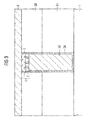
- FIG. 1 shows a simplified sectional view of a phase change memory element according to the prior art, wherein in a semiconductor substrate 10, a semiconductor switching element such as a field effect transistor is formed with a source region S, a drain region D and a gate G, which lies over a gate dielectric GD ,
- the source region S is connected, for example, via a connection element 30 to a connection electrode 40, which contacts the phase change material 50 with the properties described above.
- a further terminal counter-electrode 60 is provided, which is electrically connected via a further connection element 70 with a conductor track 80 in connection.
- the drain region D can likewise be connected to a conductor track 100 via a connection element 90.
- Reference numeral 20 denotes an insulating intermediate dielectric.
- this phase change portion of the phase change material 50 may have a corresponding crystallization expectoration or melt heating, thereby causing a phase change.
- the amorphization of the phase change material requires only a short time (short current pulse) but a high temperature (high current amount), while for the crystallization for a longer period of time, a lower current must be present.
- the readout of the set phase state can be performed by applying a sufficiently low read voltage, which does not cause critical heating. Since the measured current is proportional to the conductivity or the resistance of the phase change material, the phase states thus set can be reliably detected. In addition, since the phase change material can be electrically switched almost any number of times, non-volatile memory elements can be easily generated.
- phase-change memory elements are usually realized with a selection element such as, for example, the illustrated field effect transistor.
- this mecanicelen2ent can also be a bipolar transistor, not shown, a diode or other switching element in the same way.
- the disadvantage of such memory elements is the very high programing currents which are required for the change of the phase state.
- such currents are severely limited, e.g. With gate lengths of about 100 nm and a gate dielectric used, which withstands a voltage of 3 V, maximum currents of 100 to 200 ⁇ A are available. This results in contact surfaces for the phase change material of a maximum of 20 nm x 20 nm, which are far below lithographically realizable structures.
- connection electrode known in which a lithographically structured pad for a phase change material is reduced by spacers such that again a very small contact surface and in particular a sublithographic contact surface of the connection electrode to the phase change material can be realized.
- connection electrode and phase-GVeahsel material are not possible.
- the invention is therefore based on the object to provide a connection electrode for phase change materials, an associated phase change memory element and an associated manufacturing method, wherein an effective contact surface and thus a spatial boundary of the current path can be adjusted with high accuracy.
- connection electrode by the features of patent claim 1
- phase change memory element by the features of patent claim 7
- manufacturing method by the measures of patent claim 10.
- an electrode material of the connection electrode has a multiplicity of insulation regions, which are formed at least on the connection surface to the phase change material.
- the electrode material is structured lithographically, while the isolation regions are formed sublithographically.
- the insulation regions preferably have a grain-shaped surface cross-section, wherein they consist of SiO 2 , while the electrode material has TiN.
- the terminal electrode is preferably formed in a contact hole of a dielectric, wherein the phase change material is formed either on the surface of the dielectric outside the contact hole or only on the surface of the terminal electrode within the contact hole.
- a plurality of masking elements are preferably formed on the surface of an auxiliary dielectric, wherein, in a subsequent step, areas of the auxiliary dielectric uncovered by the masking elements are anisotropically etched back to form a plurality of isolation regions and the resulting thereby exposed areas are filled with an electrode material for forming a terminal electrode.
- the masking elements are formed sublithographically, wherein in particular so-called LPCVD processes for the production of semiconductor nanocrystals or HSG processes for the production of HSG grains (Hemispherical Silicon Grains) are used.
- LPCVD processes for the production of semiconductor nanocrystals
- HSG processes for the production of HSG grains (Hemispherical Silicon Grains) are used.
- TiN conformally as an electrode material is deposited over the whole area by means of an ALD process and removed from a common surface of the dielectric and the insulation regions.
- the terminal electrode can also be etched back to a predetermined depth in the contact hole and the phase change material can be formed only in this recess, resulting in a self-aligning process with maximum integration density.
- FIGS. 2A to 2G show simplified sectional views and a plan view for illustrating a method for producing a connection electrode for phase change materials and in particular for a phase change memory element, as can be used, for example, in a phase change memory cell according to FIG ,
- a dielectric 2 is first formed on a carrier layer 1, wherein the carrier layer 1 preferably has a monocrystalline Si semiconductor substrate and the dielectric 2 has a multilayer structure.
- the first insulating layer 2A for example, an SiO 2 layer is deposited or thermally formed on the surface of the carrier layer 1 and the Si semiconductor substrate, respectively, and then over the entire surface of the first insulating layer 2A, a second insulating layer 2B consisting of Si 3 N 4 , for example deposited.
- the advantage of this double layer is that the second insulation layer 2B can be used as etch stop layer in a later process step.
- the carrier layer 1 may also represent a metallization level or another preferably electrically conductive layer.
- a contact hole in the dielectric 2 or the first and second insulation layers 2A and 2B is subsequently formed by means of conventional lithographic methods.
- the contact hole has an extension F, wherein F defines a minimum lithographically realizable structure width.
- the contact hole may, for example, have a rectangular, square, circular or oval shape. Usually, standard etching methods are used to form this contact hole, and detailed description will be omitted below.
- a connection element 3 is now formed within this contact hole or the opening in the dielectric 2.
- a thin liner layer is deposited on the surface of the contact hole or the opening, ie on the side surfaces of the insulating layers 2A and 2B and the bottom region, and thermally cured.
- a Ti / TiN liner double layer having a layer thickness of 10nm / 10nm with the same layer thickness, ie conformal, is deposited and annealed at a predetermined temperature, thereby providing a reliable barrier layer for preventing outdiffusion of impurities into the semiconductor material or support layer 1 receives.
- the opening or contact hole is filled with an electrically conductive filling layer 3B, wherein tungsten is preferably deposited over the whole area and etched back to a predetermined depth (for example 10 nm) into the opening or into the contact hole.
- a predetermined depth for example 10 nm
- etch back can be carried out, for example, by means of a dry etching process and in particular by means of reactive ion etching (RIE, reactive ion etch).
- RIE reactive ion etching
- the liner layer 3A on the side walls of the contact hole can also be removed, thereby obtaining the recess R shown in Fig. 2A in the contact hole.
- an isotropic and in particular a wet-chemical etching method is used for the removal of the liner layer 3A.
- dry-chemical or directional etching processes can also be carried out.
- the recess R can also have a different dimension from the contact hole, wherein it preferably has a minimum realized by lithographic process structure width F to realize the required high current densities.
- an auxiliary dielectric HI is now filled in the recess R.
- SiO 2 is preferably deposited over the whole area by means of a CVD method (chemical vapor deposition) and then planarized to the surface of the dielectric 2 or of the second insulation layer 2B.
- CVD method chemical vapor deposition
- an SiO 2 layer at least 10 nm thick is deposited and planarized.
- a multiplicity of mutually spaced masking elements K are now formed at least on the surface of the auxiliary dielectric HI.
- HSG method Hemispherical Silicon Grain
- silicon grains having a size of 5 to 15 nm are formed over the entire surface of the surface of the dielectric 2 and of the auxiliary dielectric HI.
- nanocrystals or so-called nanodots can be produced as masking elements K, which have a feature size of nm to 10 nm.
- an areal density can also be set or varied very well, which is important for the exact setting of an ultimately effective terminal electrode area.
- the size of the nanodots or masking elements K is at least an order of magnitude smaller than a pattern width of the opening or the contact hole, i. the granular masking elements K have a structure width of less than 1/10 F.
- an anisotropic etching back of the region of the auxiliary dielectric HI not covered by the masking elements K up to the connection element 3 of the filling layer 3B and of the liner layer 3A can now take place.
- a plurality of separate isolation regions I are formed so to speak "island-shaped".
- standard etching methods which preferably consists of SiO 2 , selectively to the material of the masking elements K, ie to the silicon and to the material of the second insulating layer 2B.
- an undirected or only partially directed etching can be carried out, whereby the shape of the isolation regions can be influenced.
- the masking elements K (nanodots or HSG grains) located on the surface can be selectively removed from the auxiliary dielectric HI, the connection element 3 and the second insulation layer 2B or the dielectric 2.
- CMP processes chemical mechanical polishing
- TiN can be conformally deposited as electrode material E and in particular over the whole area by means of an ALD method (Atomic Layer Deposition) and finally removed from the common surface of the dielectric 2 and the insulation regions I. This removal is preferably done by means of a planarization process such as a CMP process. Again, only a selectivity to the second insulating layer 2B and the material of the isolation regions I is required.
- FIG. 2F shows a simplified plan view of the connection electrode 4, as it exists after the production step according to FIG. 2E. Consequently, the connection electrode 4 has an electrode material E whose basic shape is preferably determined lithographically by the contact hole and in which a plurality of insulation regions I at least at the connection surface are formed or stored to a phase change material.
- the preferably sublithographically formed isolation regions I thus represent a multiplicity of preferably separate islands in a "lake" of the electrode material E.
- the isolation regions I a characteristic for this manufacturing grain-like structure on the connection surface.
- the insulation regions have a cylindrical structure in cross-section to the connection surface, which essentially results from the directed etching process.
- the insulation regions I extend from the connection surface 01 to an opposite main surface 02 and are consequently formed "island-shaped", they can also be formed only on the connection surface O1 and thus on the electrode material E ". swim".
- Such an implementation may, for example, result from the use of an isotropic or partially isotropic etching process, in which only insulating material remains immediately below the masking grains K and is otherwise removed.
- all or only individual isolation areas I can also touch, as a result of which a "net-shaped" structure of the isolation areas I is created.
- a phase change material 5 is now formed at least on the surface of the connection electrode 4.
- Ge x Sb y T z is preferably deposited over the whole area, for example by means of a PVD or CVD method, although ALD (Atomic Layer Deposition) methods can also be used.
- a connection counterelectrode 6 is formed on the main surface of the phase change material 5 opposite the connection electrode 4. Preferably, this is TiN in turn deposited over the whole area by means of a PVD, CVD or ALD method.
- the variation of the terminal electrode cross-sectional area can be adjusted very precisely by varying the size and density of the nanodots, in particular when using LPCVD-Si nanocrystal methods. Due to the statistical distribution of the nanodots results in a very uniform distribution of the current flow over the contact surface of the terminal electrode, which is why you get a very high scalability of the process regardless of a lithography and the nanodots used.
- Figure 3 shows a simplified sectional view of a phase change memory element according to a second embodiment, wherein like reference numerals designate the same or corresponding layers and elements as in Figures 2A to 2G, which is why a repeated description is omitted below.
- connection electrode 4 or the SiO 2 insulation regions I and the TiN electrode material E are removed to a predetermined depth, which is approximately half the height of the original connection electrode corresponds etched back into the contact hole.
- a phase change material 5 and in particular Ge x Sb y T z deposited over the entire surface and planarized up to the surface of the dielectric 2 and the second insulating layer 2B.
- the thickness of the phase change material 5 according to FIG. 3 should typically be ⁇ 10 nm, wherein the connection electrode 4 likewise has a thickness of approximately 10 nm.
- a phase change memory cell can be completed with the usual methods, for example according to FIG.
- phase change material As a phase change material. However, it is not limited thereto and equally includes alternative phase change materials.
- the other materials are not limited to the materials described above but may include alternative materials.
- the dielectric 2 does not have to have a multilayer structure.
- the invention is not limited to a Si semiconductor substrate as a carrier layer 1, but may be formed in the same way on other carrier layers and in particular in overlying wiring layers.
Landscapes
- Engineering & Computer Science (AREA)
- Manufacturing & Machinery (AREA)
- Semiconductor Memories (AREA)
Applications Claiming Priority (1)
| Application Number | Priority Date | Filing Date | Title |
|---|---|---|---|
| DE102005014645A DE102005014645B4 (de) | 2005-03-31 | 2005-03-31 | Anschlusselektrode für Phasen-Wechsel-Material, zugehöriges Phasen-Wechsel-Speicherelement sowie zugehöriges Herstellungsverfahren |
Publications (3)
| Publication Number | Publication Date |
|---|---|
| EP1708292A2 true EP1708292A2 (fr) | 2006-10-04 |
| EP1708292A3 EP1708292A3 (fr) | 2007-09-19 |
| EP1708292B1 EP1708292B1 (fr) | 2008-09-10 |
Family
ID=36600199
Family Applications (1)
| Application Number | Title | Priority Date | Filing Date |
|---|---|---|---|
| EP06110958A Expired - Fee Related EP1708292B1 (fr) | 2005-03-31 | 2006-03-10 | Electrode de raccordement pour matériaux à changement de phase, élément de mémoire à changement de phase correspondant et procédé de fabrication associé |
Country Status (5)
| Country | Link |
|---|---|
| US (1) | US20070145346A1 (fr) |
| EP (1) | EP1708292B1 (fr) |
| JP (1) | JP2006287222A (fr) |
| KR (1) | KR100789045B1 (fr) |
| DE (2) | DE102005014645B4 (fr) |
Cited By (1)
| Publication number | Priority date | Publication date | Assignee | Title |
|---|---|---|---|---|
| KR100789045B1 (ko) | 2005-03-31 | 2007-12-26 | 인피니언 테크놀로지스 아게 | 상 변화 물질용 접속 전극, 관련 상 변화 메모리 소자, 및관련 제조 방법 |
Families Citing this family (16)
| Publication number | Priority date | Publication date | Assignee | Title |
|---|---|---|---|---|
| US7649242B2 (en) | 2006-05-19 | 2010-01-19 | Infineon Technologies Ag | Programmable resistive memory cell with a programmable resistance layer |
| DE102006023608B4 (de) * | 2006-05-19 | 2009-09-03 | Qimonda Ag | Programmierbare resistive Speicherzelle mit einer programmierbaren Widerstandsschicht und Verfahren zur Herstellung |
| US8188569B2 (en) * | 2006-12-15 | 2012-05-29 | Qimonda Ag | Phase change random access memory device with transistor, and method for fabricating a memory device |
| TW200849488A (en) * | 2007-06-08 | 2008-12-16 | Nanya Technology Corp | Deep trench and fabricating method thereof, trench capacitor and fabricating method thereof |
| US7906368B2 (en) | 2007-06-29 | 2011-03-15 | International Business Machines Corporation | Phase change memory with tapered heater |
| JP2009135219A (ja) | 2007-11-29 | 2009-06-18 | Renesas Technology Corp | 半導体装置およびその製造方法 |
| KR100956773B1 (ko) * | 2007-12-26 | 2010-05-12 | 주식회사 하이닉스반도체 | 상변화 메모리 소자 및 그 제조 방법 |
| KR100968448B1 (ko) * | 2007-12-27 | 2010-07-07 | 주식회사 하이닉스반도체 | 상변화 메모리 소자 및 그 제조 방법 |
| JP5356368B2 (ja) * | 2008-04-03 | 2013-12-04 | 株式会社東芝 | 不揮発性記憶装置及びその製造方法 |
| WO2009122583A1 (fr) * | 2008-04-03 | 2009-10-08 | 株式会社 東芝 | Dispositif d'enregistrement rémanent et son procédé de fabrication |
| KR20100041139A (ko) * | 2008-10-13 | 2010-04-22 | 삼성전자주식회사 | 상변화 물질이 3개 이상의 병렬 구조를 가짐으로써, 하나의메모리 셀에 2비트 이상의 데이터를 저장하는 멀티 레벨 셀 형성방법 |
| KR101035155B1 (ko) | 2008-11-07 | 2011-05-17 | 주식회사 하이닉스반도체 | 상변화 기억 소자 및 그 제조방법 |
| US8030130B2 (en) * | 2009-08-14 | 2011-10-04 | International Business Machines Corporation | Phase change memory device with plated phase change material |
| US20110057161A1 (en) * | 2009-09-10 | 2011-03-10 | Gurtej Sandhu | Thermally shielded resistive memory element for low programming current |
| US20110108792A1 (en) * | 2009-11-11 | 2011-05-12 | International Business Machines Corporation | Single Crystal Phase Change Material |
| JP2011211101A (ja) * | 2010-03-30 | 2011-10-20 | Sony Corp | 記憶素子及びその製造方法 |
Citations (5)
| Publication number | Priority date | Publication date | Assignee | Title |
|---|---|---|---|---|
| EP1065736A2 (fr) * | 1996-10-02 | 2001-01-03 | Micron Technology, Inc. | Procédé pour produire une petite zone de contact entre des électrodes |
| EP1355365A2 (fr) * | 2002-04-04 | 2003-10-22 | Hewlett-Packard Company | Electrode pour un élément mémoire à changement de phase |
| US20030209746A1 (en) * | 2002-05-07 | 2003-11-13 | Hideki Horii | Integrated circuit memory devices having memory cells therein that utilize phase-change materials to support non-volatile data retention and methods of forming same |
| US20050018526A1 (en) * | 2003-07-21 | 2005-01-27 | Heon Lee | Phase-change memory device and manufacturing method thereof |
| WO2005053047A1 (fr) * | 2003-11-28 | 2005-06-09 | Infineon Technologies Ag | Memoire a semi-conducteurs integree et procede pour produire une memoire a semi-conducteurs integree |
Family Cites Families (10)
| Publication number | Priority date | Publication date | Assignee | Title |
|---|---|---|---|---|
| EP0887867B1 (fr) * | 1993-11-02 | 2004-04-21 | Matsushita Electric Industrial Co., Ltd | Dispositif semiconducteur comprenant un agrégat de micro-aiguilles semi-conductrices |
| JP3603188B2 (ja) * | 2001-12-12 | 2004-12-22 | 松下電器産業株式会社 | 不揮発性メモリ及びその製造方法 |
| US6512241B1 (en) * | 2001-12-31 | 2003-01-28 | Intel Corporation | Phase change material memory device |
| KR100448893B1 (ko) * | 2002-08-23 | 2004-09-16 | 삼성전자주식회사 | 상전이 기억 소자 구조 및 그 제조 방법 |
| EP1554763B1 (fr) | 2002-10-11 | 2006-08-02 | Koninklijke Philips Electronics N.V. | Dispositif electrique contenant un materiau a changement de phase |
| DE60328960D1 (de) * | 2003-04-16 | 2009-10-08 | St Microelectronics Srl | Selbstausrichtendes Verfahren zur Herstellung einer Phasenwechsel-Speicherzelle und dadurch hergestellte Phasenwechsel-Speicherzelle |
| KR100504701B1 (ko) * | 2003-06-11 | 2005-08-02 | 삼성전자주식회사 | 상변화 기억 소자 및 그 형성 방법 |
| KR20050001169A (ko) * | 2003-06-27 | 2005-01-06 | 삼성전자주식회사 | 상변화 기억소자 형성방법 |
| KR100615586B1 (ko) * | 2003-07-23 | 2006-08-25 | 삼성전자주식회사 | 다공성 유전막 내에 국부적인 상전이 영역을 구비하는상전이 메모리 소자 및 그 제조 방법 |
| DE102005014645B4 (de) | 2005-03-31 | 2007-07-26 | Infineon Technologies Ag | Anschlusselektrode für Phasen-Wechsel-Material, zugehöriges Phasen-Wechsel-Speicherelement sowie zugehöriges Herstellungsverfahren |
-
2005
- 2005-03-31 DE DE102005014645A patent/DE102005014645B4/de not_active Expired - Fee Related
-
2006
- 2006-03-10 DE DE502006001524T patent/DE502006001524D1/de not_active Expired - Fee Related
- 2006-03-10 EP EP06110958A patent/EP1708292B1/fr not_active Expired - Fee Related
- 2006-03-28 US US11/390,560 patent/US20070145346A1/en not_active Abandoned
- 2006-03-29 JP JP2006090900A patent/JP2006287222A/ja active Pending
- 2006-03-30 KR KR1020060028796A patent/KR100789045B1/ko not_active IP Right Cessation
Patent Citations (5)
| Publication number | Priority date | Publication date | Assignee | Title |
|---|---|---|---|---|
| EP1065736A2 (fr) * | 1996-10-02 | 2001-01-03 | Micron Technology, Inc. | Procédé pour produire une petite zone de contact entre des électrodes |
| EP1355365A2 (fr) * | 2002-04-04 | 2003-10-22 | Hewlett-Packard Company | Electrode pour un élément mémoire à changement de phase |
| US20030209746A1 (en) * | 2002-05-07 | 2003-11-13 | Hideki Horii | Integrated circuit memory devices having memory cells therein that utilize phase-change materials to support non-volatile data retention and methods of forming same |
| US20050018526A1 (en) * | 2003-07-21 | 2005-01-27 | Heon Lee | Phase-change memory device and manufacturing method thereof |
| WO2005053047A1 (fr) * | 2003-11-28 | 2005-06-09 | Infineon Technologies Ag | Memoire a semi-conducteurs integree et procede pour produire une memoire a semi-conducteurs integree |
Cited By (1)
| Publication number | Priority date | Publication date | Assignee | Title |
|---|---|---|---|---|
| KR100789045B1 (ko) | 2005-03-31 | 2007-12-26 | 인피니언 테크놀로지스 아게 | 상 변화 물질용 접속 전극, 관련 상 변화 메모리 소자, 및관련 제조 방법 |
Also Published As
| Publication number | Publication date |
|---|---|
| EP1708292A3 (fr) | 2007-09-19 |
| JP2006287222A (ja) | 2006-10-19 |
| DE102005014645A1 (de) | 2006-10-05 |
| EP1708292B1 (fr) | 2008-09-10 |
| KR20060105555A (ko) | 2006-10-11 |
| KR100789045B1 (ko) | 2007-12-26 |
| DE502006001524D1 (de) | 2008-10-23 |
| US20070145346A1 (en) | 2007-06-28 |
| DE102005014645B4 (de) | 2007-07-26 |
Similar Documents
| Publication | Publication Date | Title |
|---|---|---|
| EP1708292B1 (fr) | Electrode de raccordement pour matériaux à changement de phase, élément de mémoire à changement de phase correspondant et procédé de fabrication associé | |
| DE102008016522B4 (de) | Phasenwechselspeicherzelle mit Phasenwechsel-Speichermaterial mit begrenztem Widerstand, Verfahren zur Herstellung einer deratigen Speicherzelle und integrierte Schaltung mit entsprechender Speicherzelle | |
| EP1685569B1 (fr) | Memoire a changement de phase, ensemble de memoires a changement de phase, cellule de memoire a changement de phase, reseau de cellules de memoire a changement de phase 2d, reseau de cellules de memoire a changement de phase 3d et composant electronique | |
| DE10297191B4 (de) | Phasenwechselmaterial-Speicherbauteil und Verfahren zur Herstellung | |
| DE10339070B4 (de) | Herstellungsverfahren für einen Lateralen Phasenwechsel-Speicher | |
| DE102005001902B4 (de) | Verfahren zur Herstellung einer sublithographischen Kontaktstruktur in einer Speicherzelle | |
| DE60224622T2 (de) | Einmal programmierbarer Speicher | |
| DE102018106929A1 (de) | PCRAM-Struktur mit Auswahlvorrichtung | |
| DE102004052611A1 (de) | Verfahren zur Herstellung einer mit einem Füllmaterial mindestens teilweise gefüllten Öffnung, Verfahren zur Herstellung einer Speicherzelle und Speicherzelle | |
| DE102006041849A1 (de) | Elektrisch wiederbeschreibbares nicht-flüchtiges Speicherelement und Verfahren zu dessen Herstellung | |
| DE112011101925T5 (de) | Integration eines Phasenwechselspeicherprozesses mit einer Maske | |
| DE10343209A1 (de) | Speicher- und Zugriffsbauelemente und Verfahren zu deren Herstellung | |
| DE102008041810A1 (de) | Phasenwechselspeicherbauelement für eine Mehr-Bit-Speicherung | |
| DE102008029319A1 (de) | Integrierte Schaltung mit Mehrschichtelektrode | |
| DE102004041893B4 (de) | Verfahren zur Herstellung von Speicherbauelementen (PCRAM) mit Speicherzellen auf der Basis einer in ihrem Phasenzustand änderbaren Schicht | |
| DE112008001618B4 (de) | Elektronisches Bauteil und Verfahren zum Herstellen eines solchen | |
| DE102007049786A1 (de) | Integrierte Schaltung, Speicherzellenarray, Speicherzelle, Verfahren zum Betreiben einer integrierten Schaltung, sowie Verfahren zum Herstellen einer integrierten Schaltung | |
| DE10236439B3 (de) | Speicher-Anordnung, Verfahren zum Betreiben einer Speicher-Anordnung und Verfahren zum Herstellen einer Speicher-Anordnung | |
| DE102005051973B3 (de) | Herstellungsverfahren für vertikale Leitbahnstruktur, Speichervorrichtung sowie zugehöriges Herstellungsverfahren | |
| DE102004037450A1 (de) | Schalt- bzw. Verstärker-Bauelement, insbesondere Transistor | |
| DE102007054641A1 (de) | Integrierter Schaltkreis mit Speicherzellen, und Verfahren zur Herstellung | |
| DE112021000360T5 (de) | Phasenwechselspeichereinheit mit mehreren anschlüssen | |
| DE102004054558A1 (de) | Verfahren zur Herstellung einer resistiv schaltenden Speicherzelle, hergestellte Speicherzelle sowie daraus aufgebautes Speicherbauelement | |
| DE10297692B4 (de) | Geräte und Systeme mit Haftmaterial für programmierbare Vorrichtungen, sowie Verfahren zur Herstellung | |
| DE102008013559B4 (de) | Verfahren zum Herstellen einer integrierten Schaltung, Speichermodul und integrierte Schaltung |
Legal Events
| Date | Code | Title | Description |
|---|---|---|---|
| PUAI | Public reference made under article 153(3) epc to a published international application that has entered the european phase |
Free format text: ORIGINAL CODE: 0009012 |
|
| AK | Designated contracting states |
Kind code of ref document: A2 Designated state(s): AT BE BG CH CY CZ DE DK EE ES FI FR GB GR HU IE IS IT LI LT LU LV MC NL PL PT RO SE SI SK TR |
|
| AX | Request for extension of the european patent |
Extension state: AL BA HR MK YU |
|
| PUAL | Search report despatched |
Free format text: ORIGINAL CODE: 0009013 |
|
| AK | Designated contracting states |
Kind code of ref document: A3 Designated state(s): AT BE BG CH CY CZ DE DK EE ES FI FR GB GR HU IE IS IT LI LT LU LV MC NL PL PT RO SE SI SK TR |
|
| AX | Request for extension of the european patent |
Extension state: AL BA HR MK YU |
|
| 17P | Request for examination filed |
Effective date: 20071005 |
|
| GRAP | Despatch of communication of intention to grant a patent |
Free format text: ORIGINAL CODE: EPIDOSNIGR1 |
|
| RIN1 | Information on inventor provided before grant (corrected) |
Inventor name: SEIDL, HARALD |
|
| RAP1 | Party data changed (applicant data changed or rights of an application transferred) |
Owner name: QIMONDA AG |
|
| GRAS | Grant fee paid |
Free format text: ORIGINAL CODE: EPIDOSNIGR3 |
|
| AKX | Designation fees paid |
Designated state(s): DE FR GB |
|
| GRAA | (expected) grant |
Free format text: ORIGINAL CODE: 0009210 |
|
| AK | Designated contracting states |
Kind code of ref document: B1 Designated state(s): DE FR GB |
|
| REG | Reference to a national code |
Ref country code: GB Ref legal event code: FG4D Free format text: NOT ENGLISH |
|
| REF | Corresponds to: |
Ref document number: 502006001524 Country of ref document: DE Date of ref document: 20081023 Kind code of ref document: P |
|
| PLBE | No opposition filed within time limit |
Free format text: ORIGINAL CODE: 0009261 |
|
| STAA | Information on the status of an ep patent application or granted ep patent |
Free format text: STATUS: NO OPPOSITION FILED WITHIN TIME LIMIT |
|
| 26N | No opposition filed |
Effective date: 20090611 |
|
| REG | Reference to a national code |
Ref country code: FR Ref legal event code: ST Effective date: 20091130 |
|
| PG25 | Lapsed in a contracting state [announced via postgrant information from national office to epo] |
Ref country code: DE Free format text: LAPSE BECAUSE OF NON-PAYMENT OF DUE FEES Effective date: 20091001 |
|
| PG25 | Lapsed in a contracting state [announced via postgrant information from national office to epo] |
Ref country code: FR Free format text: LAPSE BECAUSE OF NON-PAYMENT OF DUE FEES Effective date: 20091123 |
|
| GBPC | Gb: european patent ceased through non-payment of renewal fee |
Effective date: 20100310 |
|
| PG25 | Lapsed in a contracting state [announced via postgrant information from national office to epo] |
Ref country code: GB Free format text: LAPSE BECAUSE OF NON-PAYMENT OF DUE FEES Effective date: 20100310 |