EP1707763A1 - Nockenwelle, verfahren zur herstellung einer nocke für eine nockenwelle und verfahren zur herstellung der welle für eine nockenwelle - Google Patents
Nockenwelle, verfahren zur herstellung einer nocke für eine nockenwelle und verfahren zur herstellung der welle für eine nockenwelle Download PDFInfo
- Publication number
- EP1707763A1 EP1707763A1 EP04820319A EP04820319A EP1707763A1 EP 1707763 A1 EP1707763 A1 EP 1707763A1 EP 04820319 A EP04820319 A EP 04820319A EP 04820319 A EP04820319 A EP 04820319A EP 1707763 A1 EP1707763 A1 EP 1707763A1
- Authority
- EP
- European Patent Office
- Prior art keywords
- cold
- shaft
- camshaft
- forged body
- workpiece
- Prior art date
- Legal status (The legal status is an assumption and is not a legal conclusion. Google has not performed a legal analysis and makes no representation as to the accuracy of the status listed.)
- Withdrawn
Links
Images


Classifications
-
- B—PERFORMING OPERATIONS; TRANSPORTING
- B21—MECHANICAL METAL-WORKING WITHOUT ESSENTIALLY REMOVING MATERIAL; PUNCHING METAL
- B21K—MAKING FORGED OR PRESSED METAL PRODUCTS, e.g. HORSE-SHOES, RIVETS, BOLTS OR WHEELS
- B21K1/00—Making machine elements
- B21K1/20—Making machine elements valve parts
-
- B—PERFORMING OPERATIONS; TRANSPORTING
- B21—MECHANICAL METAL-WORKING WITHOUT ESSENTIALLY REMOVING MATERIAL; PUNCHING METAL
- B21C—MANUFACTURE OF METAL SHEETS, WIRE, RODS, TUBES OR PROFILES, OTHERWISE THAN BY ROLLING; AUXILIARY OPERATIONS USED IN CONNECTION WITH METAL-WORKING WITHOUT ESSENTIALLY REMOVING MATERIAL
- B21C43/00—Devices for cleaning metal products combined with or specially adapted for use with machines or apparatus provided for in this subclass
- B21C43/02—Devices for cleaning metal products combined with or specially adapted for use with machines or apparatus provided for in this subclass combined with or specially adapted for use in connection with drawing or winding machines or apparatus
-
- B—PERFORMING OPERATIONS; TRANSPORTING
- B21—MECHANICAL METAL-WORKING WITHOUT ESSENTIALLY REMOVING MATERIAL; PUNCHING METAL
- B21C—MANUFACTURE OF METAL SHEETS, WIRE, RODS, TUBES OR PROFILES, OTHERWISE THAN BY ROLLING; AUXILIARY OPERATIONS USED IN CONNECTION WITH METAL-WORKING WITHOUT ESSENTIALLY REMOVING MATERIAL
- B21C9/00—Cooling, heating or lubricating drawing material
- B21C9/005—Cold application of the lubricant
-
- B—PERFORMING OPERATIONS; TRANSPORTING
- B21—MECHANICAL METAL-WORKING WITHOUT ESSENTIALLY REMOVING MATERIAL; PUNCHING METAL
- B21C—MANUFACTURE OF METAL SHEETS, WIRE, RODS, TUBES OR PROFILES, OTHERWISE THAN BY ROLLING; AUXILIARY OPERATIONS USED IN CONNECTION WITH METAL-WORKING WITHOUT ESSENTIALLY REMOVING MATERIAL
- B21C9/00—Cooling, heating or lubricating drawing material
- B21C9/02—Selection of compositions therefor
-
- B—PERFORMING OPERATIONS; TRANSPORTING
- B21—MECHANICAL METAL-WORKING WITHOUT ESSENTIALLY REMOVING MATERIAL; PUNCHING METAL
- B21J—FORGING; HAMMERING; PRESSING METAL; RIVETING; FORGE FURNACES
- B21J3/00—Lubricating during forging or pressing
-
- B—PERFORMING OPERATIONS; TRANSPORTING
- B21—MECHANICAL METAL-WORKING WITHOUT ESSENTIALLY REMOVING MATERIAL; PUNCHING METAL
- B21J—FORGING; HAMMERING; PRESSING METAL; RIVETING; FORGE FURNACES
- B21J5/00—Methods for forging, hammering, or pressing; Special equipment or accessories therefor
-
- B—PERFORMING OPERATIONS; TRANSPORTING
- B21—MECHANICAL METAL-WORKING WITHOUT ESSENTIALLY REMOVING MATERIAL; PUNCHING METAL
- B21J—FORGING; HAMMERING; PRESSING METAL; RIVETING; FORGE FURNACES
- B21J5/00—Methods for forging, hammering, or pressing; Special equipment or accessories therefor
- B21J5/02—Die forging; Trimming by making use of special dies ; Punching during forging
-
- B—PERFORMING OPERATIONS; TRANSPORTING
- B21—MECHANICAL METAL-WORKING WITHOUT ESSENTIALLY REMOVING MATERIAL; PUNCHING METAL
- B21J—FORGING; HAMMERING; PRESSING METAL; RIVETING; FORGE FURNACES
- B21J5/00—Methods for forging, hammering, or pressing; Special equipment or accessories therefor
- B21J5/06—Methods for forging, hammering, or pressing; Special equipment or accessories therefor for performing particular operations
- B21J5/08—Upsetting
-
- B—PERFORMING OPERATIONS; TRANSPORTING
- B21—MECHANICAL METAL-WORKING WITHOUT ESSENTIALLY REMOVING MATERIAL; PUNCHING METAL
- B21K—MAKING FORGED OR PRESSED METAL PRODUCTS, e.g. HORSE-SHOES, RIVETS, BOLTS OR WHEELS
- B21K1/00—Making machine elements
- B21K1/06—Making machine elements axles or shafts
- B21K1/10—Making machine elements axles or shafts of cylindrical form
-
- F—MECHANICAL ENGINEERING; LIGHTING; HEATING; WEAPONS; BLASTING
- F01—MACHINES OR ENGINES IN GENERAL; ENGINE PLANTS IN GENERAL; STEAM ENGINES
- F01L—CYCLICALLY OPERATING VALVES FOR MACHINES OR ENGINES
- F01L1/00—Valve-gear or valve arrangements, e.g. lift-valve gear
- F01L1/02—Valve drive
- F01L1/04—Valve drive by means of cams, camshafts, cam discs, eccentrics or the like
- F01L1/047—Camshafts
-
- B—PERFORMING OPERATIONS; TRANSPORTING
- B23—MACHINE TOOLS; METAL-WORKING NOT OTHERWISE PROVIDED FOR
- B23P—METAL-WORKING NOT OTHERWISE PROVIDED FOR; COMBINED OPERATIONS; UNIVERSAL MACHINE TOOLS
- B23P2700/00—Indexing scheme relating to the articles being treated, e.g. manufactured, repaired, assembled, connected or other operations covered in the subgroups
- B23P2700/02—Camshafts
-
- F—MECHANICAL ENGINEERING; LIGHTING; HEATING; WEAPONS; BLASTING
- F01—MACHINES OR ENGINES IN GENERAL; ENGINE PLANTS IN GENERAL; STEAM ENGINES
- F01L—CYCLICALLY OPERATING VALVES FOR MACHINES OR ENGINES
- F01L1/00—Valve-gear or valve arrangements, e.g. lift-valve gear
- F01L1/02—Valve drive
- F01L1/026—Gear drive
-
- F—MECHANICAL ENGINEERING; LIGHTING; HEATING; WEAPONS; BLASTING
- F01—MACHINES OR ENGINES IN GENERAL; ENGINE PLANTS IN GENERAL; STEAM ENGINES
- F01L—CYCLICALLY OPERATING VALVES FOR MACHINES OR ENGINES
- F01L1/00—Valve-gear or valve arrangements, e.g. lift-valve gear
- F01L1/02—Valve drive
- F01L1/04—Valve drive by means of cams, camshafts, cam discs, eccentrics or the like
- F01L1/08—Shape of cams
-
- F—MECHANICAL ENGINEERING; LIGHTING; HEATING; WEAPONS; BLASTING
- F01—MACHINES OR ENGINES IN GENERAL; ENGINE PLANTS IN GENERAL; STEAM ENGINES
- F01L—CYCLICALLY OPERATING VALVES FOR MACHINES OR ENGINES
- F01L1/00—Valve-gear or valve arrangements, e.g. lift-valve gear
- F01L1/12—Transmitting gear between valve drive and valve
- F01L1/14—Tappets; Push rods
- F01L1/146—Push-rods
-
- F—MECHANICAL ENGINEERING; LIGHTING; HEATING; WEAPONS; BLASTING
- F01—MACHINES OR ENGINES IN GENERAL; ENGINE PLANTS IN GENERAL; STEAM ENGINES
- F01L—CYCLICALLY OPERATING VALVES FOR MACHINES OR ENGINES
- F01L1/00—Valve-gear or valve arrangements, e.g. lift-valve gear
- F01L1/12—Transmitting gear between valve drive and valve
- F01L1/18—Rocking arms or levers
- F01L1/181—Centre pivot rocking arms
-
- F—MECHANICAL ENGINEERING; LIGHTING; HEATING; WEAPONS; BLASTING
- F01—MACHINES OR ENGINES IN GENERAL; ENGINE PLANTS IN GENERAL; STEAM ENGINES
- F01L—CYCLICALLY OPERATING VALVES FOR MACHINES OR ENGINES
- F01L2303/00—Manufacturing of components used in valve arrangements
-
- Y—GENERAL TAGGING OF NEW TECHNOLOGICAL DEVELOPMENTS; GENERAL TAGGING OF CROSS-SECTIONAL TECHNOLOGIES SPANNING OVER SEVERAL SECTIONS OF THE IPC; TECHNICAL SUBJECTS COVERED BY FORMER USPC CROSS-REFERENCE ART COLLECTIONS [XRACs] AND DIGESTS
- Y10—TECHNICAL SUBJECTS COVERED BY FORMER USPC
- Y10T—TECHNICAL SUBJECTS COVERED BY FORMER US CLASSIFICATION
- Y10T29/00—Metal working
- Y10T29/49—Method of mechanical manufacture
- Y10T29/49229—Prime mover or fluid pump making
- Y10T29/49293—Camshaft making
-
- Y—GENERAL TAGGING OF NEW TECHNOLOGICAL DEVELOPMENTS; GENERAL TAGGING OF CROSS-SECTIONAL TECHNOLOGIES SPANNING OVER SEVERAL SECTIONS OF THE IPC; TECHNICAL SUBJECTS COVERED BY FORMER USPC CROSS-REFERENCE ART COLLECTIONS [XRACs] AND DIGESTS
- Y10—TECHNICAL SUBJECTS COVERED BY FORMER USPC
- Y10T—TECHNICAL SUBJECTS COVERED BY FORMER US CLASSIFICATION
- Y10T29/00—Metal working
- Y10T29/49—Method of mechanical manufacture
- Y10T29/49995—Shaping one-piece blank by removing material
Definitions
- the present invention relates to a camshaft for opening and closing engine valves, a method of manufacturing a cam for the camshaft, and a method of manufacturing a shaft for the camshaft.
- the assembled-type camshaft has a shaft in the form of a metal pipe fixedly mounted in a shaft insertion hole defined in a cam piece, by means of press-fitting or the like.
- a round rod of elongated steel having a volume that corresponds to a cam to be produced, is heated to a temperature in a range from 1250 to 1280 °C, and then subjected to a hot forging process by striking.
- Japanese Laid-Open Patent Publication No. 2001-355709 and Japanese Laid-Open Patent Publication No. 2002-147572 disclose the technical concept of employing fine blanking to reduce a die-induced deformation, for achieving both desired forming accuracy and reducing manufacturing costs.
- fine blanking since fine blanking is essentially a shearing process, it must be performed in a manner that minimizes ruptured surfaces or die-induced deformations. If a ruptured surface or die-induced deformation is formed on the surface of the produced cam, then surface pressure on the cam tends to be locally increased when the cam surface presses a valve.
- the assembled-type camshaft includes a cam and a shaft, which are integrally combined with each other. If the cam were to slip against the shaft, then the crankshaft that operates the camshaft and the valve that is operated by the camshaft are brought out of synchronism with each other.
- Japanese Laid-Open Patent Publication No. 7-293666 proposes a technique of providing a rotation prevention mechanism in a fitting hole of the cam.
- Japanese Laid-Open Patent Publication No. 11-107712 discloses a technique for fitting a cam over a hollow shaft while enlarging the shaft by plastic deformation to fix the cam in place.
- Japanese Laid-Open Patent Publication No. 52-50963 discloses a technique for forming a camshaft at a low cost by means of cold forging.
- the technique disclosed in Japanese Laid-Open Patent Publication No. 52-50963 concerns the production of a camshaft for a brake drum, wherein the camshaft is combined with a cam in the form of a flat plate.
- the disclosed technique is not applicable to the production of an engine camshaft, because a different type of cam is used to open and close the valves in an engine.
- the shaft and cam are separately produced and then assembled into a camshaft, then the shaft and cam need to be machined to form a rotation prevention mechanism, in order to prevent the cam from rotating relatively to the camshaft. Therefore, an additional machining process for forming such a rotation prevention mechanism is required.
- the rotation prvention mechanism is incorporated therein, the shaft and the cam tend to be complex in shape.
- Another object of the present invention is to provide a method of manufacturing a cam for a camshaft by performing a succession of cold forging steps, thereby dispensing with a final finishing (machining) process, and achieving high dimensional accuracy.
- Still another object of the present invention is to provide a method of manufacturing a shaft for a camshaft with a reduced number of manufacturing steps, wherein a cam that is press-fitted over the shaft is less prone to sliding circumferentially.
- a camshaft comprises a shaft formed by cold forging, wherein a powdery lubricant is applied to the surface of the camshaft, and a cam is mounted on the shaft by press-fitting the cam over the shaft.
- the cam By thus press-fitting the cam over the shaft, the cam is firmly fixed to the shaft, and no additional process steps are required to secure the cam. Since the cam is fixed in position by press-fitting, there is no need for a rotation prevention mechanism or any process of forming the rotation prevention mechanism. Consequently, the camshaft can be manufactured using a reduced number of steps, enabling higher productivity. Productivity is also increased since the shaft itself is formed by cold forging.
- the powdery lubricant may be lime or borax.
- the shaft has a flat surface formed by shearing, then the shaft can avoid interference with another member such as a connecting rod or the like.
- the shearing process for forming the flat surface maintains the dimensional accuracy of the shaft, which has been formed by cold forging.
- the shaft has a cut surface defined on a side thereof by shearing, then the shaft can avoid interference with another member such as a connecting rod or the like.
- the shearing process for forming the cut surface maintains the dimensional accuracy of the shaft, which has been formed by cold forging.
- the cam may have a shaft insertion hole defined therein.
- the shaft insertion hole can easily be formed in the cam by punching.
- the camshaft may further include a gear mounted on the shaft, wherein the gear is press-fitted over the shaft.
- the gear may be made of synthetic resin and have a metal bushing disposed centrally therein, wherein the metal bushing is press-fitted over the shaft.
- the shaft may have a step providing different diameters on both sides thereof.
- a method of manufacturing a cam for a camshaft of an engine According to the method, preliminary profile upsetting is performed on a forging blank having a volume which is greater, by a predetermined amount, than a final product, thereby forming a first cold-forged body having a rough shape.
- Profile drawing is performed on the first cold-forged body to form a second cold-forged body, wherein the second cold-forged body has excessive material, which flows along a profile thereof, and being formed as a burr on an outer surface thereof.
- the second cold-forged body is punched to form inner and outer surfaces simultaneously thereon, thereby forming a third cold-forged body, wherein the burr is removed from the outer surface and a relief hole, which is smaller in diameter than a shaft insertion hole for the camshaft, is formed therein.
- the third cold-forged body is pressed into a fourth cold-forged body having a predetermined thickness, wherein excessive material is formed as a burr on the inner surface thereof.
- the fourth cold-forged body is punched to remove the burr from the inner surface, thereby forming a fifth cold-forged body having a hole corresponding to the shaft insertion hole.
- the fifth cold-forged body is ironed simultaneously on inner and outer surfaces thereof, thereby forming a final product.
- the final product thus produced does not require a finishing process, such as a cutting or polishing process on a cam (profile) surface, and has desired dimensional accuracy and surface roughness.
- first and second beveled facets may be formed on peripheral portions of the first cold-forged body.
- the first beveled facet is formed on a peripheral portion of a surface of the first cold-forged body, which is positioned near the burr formed by profile drawing on the outer surface
- the second beveled facet is formed on a peripheral portion of a surface of the first cold-forged body, which is opposite to the first-mentioned surface thereof, wherein the first beveled facet has an area greater than the second beveled facet. Since the area of the first beveled facet is greater than the area of the second beveled facet, the profile drawing process is smoothly performed.
- a method of manufacturing a shaft for a camshaft of an engine comprising the steps of coating an outer circumferential surface of a cylindrical blank with a powdery lubricant, axially pressing an end of the blank to draw the blank into a workpiece having a plurality of diameters, axially pressing the end of the workpiece and fixing an opposite end thereof, so as to expand a portion of the workpiece radially outwardly into an annular expanded portion, and axially pressing the annular expanded portion into a flange while drawing the workpiece into a workpiece having a plurality of diameters, wherein the steps of axially pressing the end of the blank and the end of the workpiece are performed by cold forging.
- the cam that is press-fitted over the shaft is less liable to slip in the circumferential direction, and the finished product can be manufactured in a reduced number of steps.
- a camshaft, a method of manufacturing a cam for the camshaft, and a method of manufacturing a shaft for the camshaft according to an embodiment of the present invention will be described in detail below with reference to the accompanying drawings.
- FIG. 1 schematically shows an engine 12, incorporating an assembled-type camshaft 10 manufactured by a method of manufacturing a cam for a camshaft according to an embodiment of the present invention.
- the camshaft 10 is used in the engine 12, which may be a single-cylinder engine, for example.
- the camshaft 10 pushes push rods 16 (one shown) upwardly in synchronism with rotation of a crankshaft 14, in order to operate rocker arms 18 (one shown) for opening and closing valves 20.
- the valves 20 include two valves, i.e., intake and exhaust valves, which are associated with respective rocker arms 18 and respective push rods 16.
- the camshaft 10 has two cams 22, 24, which are angularly held out of phase with each other, i.e., angularly spaced from each other, for individually pushing the respective push rods 16 upwardly.
- the camshaft 10 has a shaft 26 formed by cold forging, cams 22, 24 press-fitted over the shaft 26, and a gear 28 made of a synthetic resin, e.g., nylon, mounted on an end of the shaft 26 and held in mesh with a drive gear 14a (see FIG. 1) on the crankshaft 14 for rotating the shaft 26 about its own axis.
- the gear 28 has a metal bushing 28a disposed centrally therein, which is made of carbon steel such as S35C (carbon steel for use in machines and structures having a carbon content in a range from 0.32 to 0.38 weight %) according to JIS G4051, for example.
- the metal bushing 28a is press-fitted over the shaft 26.
- the gear 28 is formed by injection-molding the synthetic resin, preferably with the metal bushing 28a inserted in position. Since the metal bushing 28a is mounted in the gear 28, the gear 28 can reliably be press-fitted over and tightened on the shaft 26.
- the synthetic resin gear 28 can be manufactured with high production efficiency, using a process such as injection molding, and is lighter than metal gears.
- the gear 28 may also be made of metal, by pressing, machining, or sintering, depending on the specifications of the engine 12.
- Each of the cams 22, 24 has a cam (profile) surface 30 held in contact with a lower end face of the push rod 16 for pressing the push rod 16 upwardly, and a shaft insertion hole 32 defined therethrough for insertion of the shaft 26 therein (see FIG. 2).
- step S1 as shown in FIG. 3, a rod (not shown) is cut to a predetermined length, for producing a cylindrical billet 34, which serves as a forging blank (see FIGS. 4 through 6).
- the billet 34 has a volume, which does not correspond to the volume of the cam 22 or 24 as finally produced, but which corresponds to the sum of the volume of the finally produced cam 22 or 24 and the volume of burrs to be removed therefrom.
- the billet 34 may be produced by shearing a coil member (not shown).
- step S2 the billet 34 produced in step S1 is loaded into a cavity 38 of a first cold-forging die assembly 36, as shown in FIG. 10, and pressed by a punch 40 for performing preliminary profile upsetting.
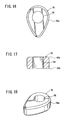
- the billet 34 is pressed downwardly by the punch 40 into a first cold-forged body 42 (see FIGS. 7 through 9) having a rough shape which is thicker than a final product, and which has an outer profile (width) greater than the final product.
- the first cold-forged body 42 includes a portion, which has been plastically deformed by the punch 40, but which has not flowed sufficiently toward a tip end 44 providing a cam surface. Therefore, the tip end 44 is thinner than the remaining portion of the first cold-forged body 42, as shown in FIG. 9.
- the first cold-forged body 42 has a first annular slanted beveled facet 46a formed on the peripheral portion of an upper surface (one surface) thereof, and a second annular slanted beveled facet 46b formed on the peripheral portion of a lower surface (other surface) thereof.
- the first annular slanted beveled facet 46a on the upper surface has an area which is greater than that of the second annular slanted beveled facet 46b on the lower surface (see FIG. 11).
- the punch 40 is positioned upwardly, whereas a lower die 36a is positioned downwardly.
- the first and second beveled facets 46a, 46b on the upper and lower surfaces of the first cold-forged body 42 are effective to prevent a ruptured surface from producing a burr, when a burr 56 on the outer surface of the first cold-forged body 42 is cut off in step S4, as described later. Therefore, no deburring process in required in step S4, and thus step S4 can be simplified.
- step S3 the first cold-forged body 42 produced in step S2 is loaded into a cavity 50 of a second cold-forging die assembly 48, as shown in FIG. 15, and pressed by a punch 52 for performing profile drawing.
- the cavity 50 which is defined between the punch 52 and a lower die 48a of the second cold-forging die assembly 48, has a width A, which is smaller than the width B of the cavity 38 in the first cold-forging die assembly 36 (see FIGS. 10 and 15 for comparison).
- the first cold-forged body 42 is pressed downwardly by the punch 52, to cause the plastically deformed material to flow along the profile of an outer circumferential surface that corresponds to the shape of the final product, thereby forming a second cold-forged body 54 (see FIGS. 11 through 14) wherein the tip end 44a, which was not sufficiently filled in the preliminary profile upsetting process, is sufficiently filled with the plastically deformed material.
- the second cold-forged body 54 has an annular burr 56 on the outer circumferential surface thereof near its upper surface, the burr 56 being formed from an excessive material that has flowed along the profile of the outer circumferential surface (see FIG. 13).
- the profile drawing process is performed along the profile of the outer circumferential surface, without affecting the first and second beveled facets 46a, 46b that were formed in the previous process.
- step S4 the second cold-forged body 54 produced in step S3 is loaded into a third cold-forging die assembly 58, as shown in FIG. 19, and pressed downwardly by a hollow punch 64 inserted into a hole 62 defined in a die 60, thereby removing the burr 56 projecting on the outer circumferential surface of the second cold-forged body 54.
- the second cold-forged body 54 is punched at a position where the shaft 26 will be inserted, by a fixed punch 68 which is fixed to a lower die 58a of the third cold-forging die assembly 58, thereby forming a relief hole 66 therein, wherein the diameter of the relief hole 66 is smaller than the inside diameter of the shaft insertion hole 32 in the final product.
- the second cold-forged body 54 is punched to produce inner and outer surfaces simultaneously by the third cold-forging die assembly 58.
- a third cold-forged body 70 (see FIGS. 16 through 18) is formed, which has a ruptured surface free of burrs and high surface accuracy, because the outer circumferential surface is ironed when the burr 56 is punched off. Further, the relief hole 66 defined in the inner surface is smaller in diameter than the shaft insertion hole 32.
- the relief hole 66 is formed to allow excessive material to flow only on the inner surface, while the outer circumferential surface is constrained, in the following and subsequent steps.
- step S5 the third cold-forged body 70 produced in step S4 is loaded into a cavity of a fourth cold-forging die assembly 72, as shown in FIG. 23. While the outer circumferential surface of the third cold-forged body 70 is constrained by a die surface of the fourth cold-forging die assembly 72, the third cold-forged body 70 is pressed downwardly by a punch 76 having an annular step 74 that projects a certain length toward a lower die 72a, thereby providing the cold-forged body with a predetermined thickness and forming an excessive flowing material, as a burr 78, on the inner surface thereof.
- a fourth cold-forged body 82 (see FIGS. 20 through 22) is formed, having guide holes 80 in the relief hole 66 near the upper and lower surfaces, in preparation for punching the inner surface in the next step, and also having a thickness which is essentially the same as the thickness of the final product.
- the fourth cold-forged body 82 has a through hole 84 extending transversely between the guide holes 80, for allowing material to flow easily when the burr 78 is removed from the inner surface in the next step.
- step S6 the fourth cold-forged body 82 produced in step S5 is loaded into a cavity of a fifth cold-forging die assembly 86, as shown in FIG. 27. While the outer circumferential surface of the fourth cold-forged body 82 is constrained by a die surface of the fifth cold-forging die assembly 86, the upper surface of the fourth cold-forged body 82 is pressed downwardly by a hollow punch 88. Thus, a fixed punch 90 which is fixed to a lower die 86a of the fifth cold-forging die assembly 86 removes the burr 78 from the inner surface of the fourth cold-forged body 82 in an inner surface punching process.
- the burr 78 is punched off the inner surface of the fourth cold-forged body 82, thereby forming a fifth cold-forged body 92 (see FIGS. 24 through 26) having a shaft insertion hole 32 defined therein which has a predetermined inside diameter.
- step S7 the fifth cold-forged body 92 produced in step S6 is loaded into a cavity of a sixth cold-forging die assembly 94, as shown in FIG. 31. While the outer circumferential surface of the fifth cold-forged body 92 is constrained by a die surface of the sixth cold-forging die assembly 94, the upper surface of the fifth cold-forged body 92 is pressed downwardly by a hollow punch 98. Thus, a fixed punch 96 which is fixed to a lower die 94a of the sixth cold-forging die assembly 94 enters the shaft insertion hole 32, simultaneously ironing the inner and outer surfaces of the fifth cold-forged body 92.
- step S8 a cam 22, 24 is produced, which has a predetermined surface roughness on inner and outer surfaces thereof.
- the processes, from step S2 to step S8, may be performed continuously by a header or a forging press.
- the shaft insertion holes 32 of the cams 22 and 24 may have different diameters, depending on the diameters at the portions of the shaft 26 where the cams 22, 24 are to be press-fitted.
- fixed punches 96 having corresponding different diameters may be used.
- the first through sixth cold-forging die assemblies 36, 48, 58, 72, 86, 94 are used to successively perform a plurality of respective cold-forging processes, including the preliminary profile upsetting process, the profile drawing process, the process of simultaneously forming inner and outer surfaces, the pressing process of forming excessive material as a burr 78 on the inner surface, the process of punching the burr 78 off the inner surface, and the process of simultaneously ironing the inner and outer surfaces, thereby producing a final product, wherein the final product does not require final finishing (machining) on the cam (profile) surface and achieves high dimensional accuracy.
- the final product is free of any ruptured surface or die-induced deformations on the outer circumferential surface thereof, while having a predetermined surface roughness on the cam surface, and provides a predetermined fitting dimension for the shaft insertion hole into which the shaft is inserted.
- a billet 34 which has a volume greater than the volume of the final product.
- Excessive material, as a burr 56 is formed on the outer circumferential surface of the cold-forged body by the profile drawing process, and further excessive material, as a burr 78, is formed on the inner surface of the cold-forged body by the pressing process, wherein the burr 56 on the outer circumferential surface and the burr 78 on the inner surface are punched off.
- the billet material flows in a single direction toward the outer circumferential surface during the profile drawing process, and, since the outer circumferential surface is constrained during the pressing process, the billet material flows in a single direction toward the inner surface during the pressing process, wherein excessive burrs 56, 78 are removed after the respective profile drawing and pressing processes. Therefore, the final product does not require finishing, such as by cutting or grinding, but nevertheless maintains a highly accurate surface roughness and high dimensional accuracy.
- the shape of the shaft 26 will be described below with reference to FIG. 32.
- the shaft 26 has a first diameter portion 26a having a smallest diameter at the end on which the gear 28 is mounted.
- the shaft 26 also has a second diameter portion 26b positioned adjacent to the first diameter portion 26a in the direction indicated by the arrow C toward the other end 26e.
- the second diameter portion 26b has a diameter slightly greater than the first diameter portion 26a.
- the gear 28, when press-fitted over the first diameter portion 26a is positioned by a small step 27a that is disposed between the first diameter portion 26a and the second diameter portion 26b.
- the shaft 26 also has a third diameter portion 26c positioned adjacent to the second diameter portion 26b in the direction indicated by the arrow C and having a diameter slightly greater than the second diameter portion 26b.
- the cam 22, when press-fitted over the second diameter portion 26b is positioned by a small step 27b that is disposed between the second diameter portion 26b and the third diameter portion 26c.
- the shaft 26 further has a fourth diameter portion 26d positioned adjacent to the third diameter portion 26c in the direction indicated by the arrow C and having a diameter slightly greater than the third diameter portion 26c.
- the fourth diameter portion 26d has two flat (cut) surfaces 130 parallel to the axis thereof for preventing the shaft 26 from interfering with an end of a connecting rod 33 (see FIG. 1) and hence allowing the camshaft 10 to be positioned closely to the connecting rod 33.
- the shaft 26 has a flange 26f disposed between the fourth diameter portion 26d and the other end 26e, for positioning the shaft 26 when the camshaft 10 is assembled in the engine 12.
- the cam 24, when press-fitted over the fourth diameter portion 26d, is positioned by the flange 26f.
- the first through fourth diameter portions 26a through 26d are shown with exaggerated differences to indicate that they have different diameters, for easier understanding of the present invention. However, in actuality, the differences between the respective diameters are so small that the first through fourth diameter portions 26a through 26d appear to have substantially the same diameter.
- a cutting jig 100 for forming the flat surfaces 130 on the shaft 26 will be described below with reference to FIG. 33.
- the cutting jig 100 comprises a workpiece holder 102 having a hole 102a for inserting the first through fourth diameter portions 26a through 26d therethrough, a cutter 104 for forming the flat surfaces 130, a holder guide 106 into which the workpiece holder 102 is slidably inserted, a movable die 108 for holding the other end 26e of the shaft 26 and pushing the workpiece holder 102 into the holder guide 106, and a back plate 110 having gas springs 110a, i.e., springs or other mechanism for forcibly returning the workpiece holder 102, and for pushing the workpiece holder 102 out of the holder guide 106 after the flat surfaces 130 have been formed on the shaft 26.
- the movable die 108, the workpiece holder 102, the holder guide 106, and the back plate 110 are successively arranged in the order described.
- the hole 102a in the workpiece holder 102 has a portion where the fourth diameter portion 26d of the shaft 26 is inserted, the portion being held in communication with a hole 102b defined in the workpiece holder 102 for inserting the cutter 104 therein.
- the hole 102b is of a substantially elongate rectangular shape for setting the cutter 104, and communicates perpendicularly to the hole 102a.
- the cutter 104 has two parallel blades 104a for cutting off portions of the shaft 26 to form the flat surfaces 130, and a slanted surface 104b inclined so as to become progressively closer to the axis of the workpiece holder 102 in the direction indicated by the arrow D toward the holder guide 106.
- the holder guide 106 has a guide surface 106b for abutment against the slanted surface 104b of the cutter 104, the guide surface 106b being inclined so as to become progressively closer to the axis of the holder guide 106 in the direction indicated by the arrow D.
- a blank in the form of a round (cylindrical) rod of carbon steel is etched using oxalic acid to make the surface thereof porous.
- lime may be applied to a phosphate coating on the blank to make the surface thereof porous.
- etching the blank with oxalic acid is more effective to make the surface porous and hence is preferable to using the phosphate coating.
- the carbon steel material making up the blank may be S35C, as referred to above. If liquid nitriding is performed on the blank, then the blank may be made of carbon steel having a lower carbon content.
- step S12 the blank is drawn to a predetermined outside diameter using a die 200 (see FIG. 35).
- the blank is lubricated by coating or ejecting a lubricant 202 onto the blank. Since the surface of the blank has been made porous in step S11, the lubricant 202 fills the pores, making the blank slidable against the die 200. Therefore, the blank can be drawn smoothly through the die 200. The lubricated blank is also prevented from seizure, thus prolonging its service life.
- the lubricant 202 may comprise a powdery lubricant, such as lime or borax dissolved in water or the like, or processed into a paste.
- the powdery lubricant 202 makes the cams 22, 24 resistant to slippage in the circumferential direction of the shaft 26, allowing the camshaft 10 to rotate in synchronism with rotation of the crankshaft 14 when the camshaft 10 is assembled in the engine 12.
- step S12 the diameter of the shaft 26 is reduced as it is drawn, so it may be set at a small value for the purpose of filling the lubricant 202 in the blank.
- step S13 the blank is cut, for example by shearing, to a predetermined length, thus forming a workpiece 204 from which the shaft 26 is made.
- step S14 the workpiece 204 is drawn by cold forging (see FIG. 36) using a die 206 and a punch 208.
- the die 206 has a hole 210 therein, formed by a first hole 210a which is open upwardly and a second hole 210b which communicates with the first hole 210a and is slightly smaller in diameter than the first hole 210a.
- the first hole 210a serves to draw a portion of the workpiece 204 where the other end 26e and the flange 26f will be formed
- the second hole 210b serves to draw a portion of the workpiece 204 where the first through fourth diameter portions 26a through 26d will be formed.
- the workpiece 204 is inserted into the hole 210 while being pushed downwardly axially by the punch 208, and is drawn into predetermined diameters by the first hole 210a and the second hole 210b.
- the punch 208 is pulled back upwardly, and a knockout pin 212 positioned in a lower portion of the hole 210 is lifted to eject the workpiece 204 out of the hole 210.
- step S14 and subsequence steps S15 and S16, the workpiece 204 is inserted into dies 206, 214 and 230 with the portion thereof which will become the first diameter portion 26a being positioned downwardly and the portion which will become the other end 26e being positioned upwardly.
- step S15 the workpiece 204 is cold-forged to form a flange thereon, using a die 214 (see FIG. 37) having a hole 214a therein that is slightly smaller in diameter than the first hole 210a of the die 206, and further having a punch 216 with a bottomed hole 216a therein, which is of substantially the same diameter as the hole 214a.
- the hole 216a in the punch 216 is aligned with the upper end of the workpiece 204, and the punch 216 is pressed axially downwardly until the upper end surface of the workpiece 204 abuts against the bottom of the hole 216a.
- the upper portion of the workpiece 204 is then drawn by the hole 216a, and a part of the workpiece 204 is plastically expanded radially outwardly to form an annular expanded portion 218 between the lower surface of the punch 216 and the upper surface of the die 214.
- the annular expanded portion 218 serves as a basis for the flange 26f.
- the bottom of the hole 216a has a single ridge 217 extending through the center thereof.
- the ridge 217 When the ridge 217 is pressed against the upper surface of the workpiece 204, it forms a central groove 221 in the upper surface of the workpiece 214, which acts as a stop for preventing the workpiece 204 from rotating.
- a lower surface of the workpiece 204 is held against an upper surface of the knockout pin 222.
- the upper surface of the knockout pin 222 has a protrusion 224 disposed centrally thereon.
- the protrusion 224 serves to prevent the workpiece 204 from wobbling. Since the knockout pin 222 is supported by a bolster 226, the knockout pin 222 reliably presses the lower surface of the workpiece 204 to prevent the workpiece 204 from being displaced, so that the expanded portion 218 is formed reliably.
- the groove 221 formed by the ridge 217 of the punch 216 can also be used to inspect the displacement accuracy of the workpiece 204, so that a displaced state of the workpiece 204 can be corrected, if necessary, based on the results of the inspection.
- the punch 216 is pulled back upwardly, and the knockout pin 222 is lifted to eject the workpiece 204 out of the hole 214a.
- step S16 the workpiece 204 is finished by cold forging using a die 230 and a punch 232 (see FIG. 38).
- the die 230 has a hole 230a defined therein, which includes a first diameter portion 234a, a second diameter portion 234b, a third diameter portion 234c, and a fourth diameter portion 234d, arranged successively upwardly in the order named. These first through fourth diameter portions 234a through 234d draw the workpiece 204 to form the first diameter portion 26a, the second diameter portion 26b, the third diameter portion 26c, and the fourth diameter portion 26d, respectively.
- step S16 the basic configuration of the shaft 26 is now formed.
- the step between the first diameter portion 234a and the second diameter portion 234b of the die 230 is tapered downwardly for smoothly drawing the workpiece 204.
- the steps between the second through fourth diameter portions 234b through 234d are similarly tapered.
- the punch 232 has a bottomed hole 232a defined therein.
- the workpiece 204 is inserted into the hole 230a, and the hole 232a is aligned with the upper surface of the workpiece 204.
- the punch 232 is pressed downwardly, the bottom of the hole 232a presses the upper surface of the workpiece 204, and the workpiece 204 is drawn and finished by the hole 230a.
- the expanded portion 218 is sandwiched between the lower surface of the punch 232 and the upper surface of the die 230, and is axially compressed.
- the material of the expanded portion 218 plastically flows radially outwardly into a flat shape, thus forming the flange 26f.
- the finished workpiece 204 serves as the shaft 26.
- step S16 After being finished in step S16, the punch 232 is pulled back upwardly, and a knockout pin 235 disposed in a lower portion of the hole 230a is lifted to eject the shaft 26 out of the hole 230a.
- the shaft 26 is thereby formed by successive cold-forging processes. Since the workpiece 204 is coated with the lubricant 202 in step S12, the successive cold-forging processes can be performed smoothly without danger of possibly cracking the workpiece 204 or creating flaws in the workpiece 204.
- the lubricant 202 is also effective to prevent the dies 200, 206, 214, 230 and the punches 208, 216, 232 from suffering seizure.
- the cold-forging processes do not require heating, and hence processes or facilities for performing heating are not required.
- the lubricant 202 is filled in the pores formed in the surface of the workpiece 204, following step S12, the lubricant 202 can effectively perform a lubricating function in steps S13 through S16. If necessary, however, the workpiece 204 and the dies and punches may be coated with working oil, such as header oil or the like, for providing auxiliary lubrication and cooling during such steps.
- working oil such as header oil or the like
- step S17 the two flat (cut) surfaces 130 are formed on the fourth diameter portion 26d of the shaft 26 by the cutting jig 100 (see FIG. 33).
- the first through fourth diameter portions 26a through 26d of the shaft 26 are inserted into the hole 102a of the workpiece holder 102.
- the cutter 104 is set in the hole 102b of the workpiece holder 102. At this time, the two blades 104a abut against the fourth diameter portion 26d parallel to the shaft 26.
- the movable die 108 holds the other end 26e of the shaft 26, the workpiece holder 102 and the cutter 104 are pressed into the hole of the holder guide 106.
- the movable die 108 exerts drive forces sufficiently greater than the spring forces of gas springs 110a, thus reliably moving the workpiece holder 102 and the cutter 104 in the direction indicated by the arrow D.
- the slanted surface 104b of the cutter 104 is guided by the guide surface 106a and is progressively displaced along the hole 102b in a radial direction perpendicular to the direction indicated by the arrow D.
- the blades 104a cut off opposite sides of the fourth diameter portion 26d, forming the flat surfaces 130.
- the movable die 108 is pulled back to allow the workpiece holder 102 to return under the bias of the gas springs 110a.
- the shaft 26 is pulled out of the hole 102a.
- flat surfaces 130 can be formed on the shaft 26 in a simple process, by setting the shaft 26 and the cutter 104 in the workpiece holder 102 and then moving the workpiece holder 102 in the direction indicated by the arrow D.
- the shaft 26 Since flat surfaces 130 are formed when the side portions of the shaft 26 are cut off by the blades 104a of the cutter 104, the shaft 26 is free of plastic deformation such as expansion or the like. Accordingly, dimensional accuracy of the shaft 26, which has been formed in the processes up to step S17, can be maintained.
- the cut-off portions are discharged along a predetermined path defined in the die.
- step S18 the cams 22, 24 are successively press-fitted over the shaft 26.
- the cam 22 is press-fitted up to a position on the fourth diameter portion 26d and positioned by the flange 26f.
- the cam 24 is press-fitted up to a position on the second diameter portion 26b, and positioned by the step formed between the second diameter portion 26b and the third diameter portion 26c.
- step S19 the gear 28 is press-fitted over the shaft 26.
- the metal bushing 28a of the gear 28 is press-fitted over the first diameter portion 26a, and positioned by the step formed between the first diameter portion 26a and the second diameter portion 26b.
- steps S18 and S19 the cams 22, 24 and the gear 28 are press-fitted over the shaft 26 at appropriate respective angles or phases around the axis of the shaft 26.
- the flat surfaces 130 of the shaft 26 may be used as reference surfaces for establishing the angles of the cams 22, 24 and the gear 28.
- the powdery lubricant when used, the powdery lubricant only physically attaches to the surface of the blank, and tends to fall off the surface of the blank when the blank is cold-forged. Thus, when the cams and the gears are subsequently press-fitted over the workpiece, they are less liable to slip due to large tightening forces. If a chemically bonded lubricant, such as a stearic-acid metallic soap is used (bonderized), then since it remains unremoved when the blank is cold-forged, the cams and the gears that are subsequently press-fitted over the workpiece are more prone to slippage.
- a chemically bonded lubricant such as a stearic-acid metallic soap
- a phosphoric acid coating is applied for facilitating bonding to the metallic soap, it is preferable to use oxalic acid for etching the blank.
- the lubricant 202 has a coefficient of friction in the range from 0.03 to 0.07, which is equivalent to that which is provided by a bonderizing process, then the lubricant provides sufficient lubrication for the workpiece 204 when it is cold-forged.
- the cams 22, 24 and the gear 28 are press-fitted over the shaft 26 in steps S18 and S19, and do not need to be separately fixed in position. Therefore, the camshaft 10 can be fabricated with high productivity. Furthermore, the cams 22, 24 and the gear 28 do not require a separate rotation prevention mechanism, such as a key, a screw, or require fixation based on plastic machining, brazing, or the like, and hence processes for forming such a rotation prevention mechanism can be dispensed with. Consequently, the shapes of the cams 22, 24 and the gear 28 can be simplified.
- the shaft 26 can be fabricated with high productivity, because it is basically formed by cold forging alone, and does not require other machining steps such as cutting, etc. Because the blank from which the shaft 26 is formed is coated with the lubricant 202, it can be cold-forged easily and smoothly.
- the lubricant 202 is in the form of a powdery lubricant dissolved in water or the like, and provides sufficient slip torques for the cams 22, 24 and the gear 28 that are press-fitted over the shaft 26. Therefore, operation of the camshaft 10 is kept in synchronism with the crankshaft 14.
- the processes involved in forming the shaft 26 may successively be performed by a single machine.
- the processes in steps S14 through S17 may be performed by a single machine (including the cutting jig 100), to process the workpiece 204 while feeding the workpiece 204 successively through the processes performed by the machine.
- the camshaft 10 is illustrated as being used in the single-cylinder engine 12. If the camshaft 10 is used in an engine having two or more cylinders, then the number of cams of the camshaft 10 may be increased depending on the number of cylinders of the engine.
Landscapes
- Engineering & Computer Science (AREA)
- Mechanical Engineering (AREA)
- General Engineering & Computer Science (AREA)
- Valve-Gear Or Valve Arrangements (AREA)
- Forging (AREA)
Applications Claiming Priority (4)
| Application Number | Priority Date | Filing Date | Title |
|---|---|---|---|
| JP2003414415A JP2006169960A (ja) | 2003-12-12 | 2003-12-12 | カムシャフト |
| JP2003414442A JP4610887B2 (ja) | 2003-12-12 | 2003-12-12 | カムシャフト用シャフトの製造方法 |
| JP2003414521A JP2006169961A (ja) | 2003-12-12 | 2003-12-12 | カムシャフト用カムの製造方法 |
| PCT/JP2004/018510 WO2005056986A1 (ja) | 2003-12-12 | 2004-12-10 | カムシャフト、カムシャフト用のカムの製造方法及びカムシャフト用シャフトの製造方法 |
Publications (2)
| Publication Number | Publication Date |
|---|---|
| EP1707763A1 true EP1707763A1 (de) | 2006-10-04 |
| EP1707763A4 EP1707763A4 (de) | 2010-06-23 |
Family
ID=34681970
Family Applications (1)
| Application Number | Title | Priority Date | Filing Date |
|---|---|---|---|
| EP04820319A Withdrawn EP1707763A4 (de) | 2003-12-12 | 2004-12-10 | Nockenwelle, verfahren zur herstellung einer nocke für eine nockenwelle und verfahren zur herstellung der welle für eine nockenwelle |
Country Status (3)
| Country | Link |
|---|---|
| US (1) | US7628129B2 (de) |
| EP (1) | EP1707763A4 (de) |
| WO (1) | WO2005056986A1 (de) |
Families Citing this family (11)
| Publication number | Priority date | Publication date | Assignee | Title |
|---|---|---|---|---|
| JP4906676B2 (ja) * | 2007-10-29 | 2012-03-28 | 武蔵精密工業株式会社 | カムロブの成形方法 |
| US7895743B2 (en) * | 2007-12-18 | 2011-03-01 | Caterpillar Inc. | Refurbished camshaft and method |
| US7895982B2 (en) * | 2007-12-18 | 2011-03-01 | Caterpillar Inc. | Refurbished camshaft and method |
| CN102363194B (zh) * | 2011-07-21 | 2013-01-02 | 南京迪威尔高端制造股份有限公司 | 一种确定圆截面多级台阶轴自由锻造毛坯辅料料重的方法 |
| US9481932B2 (en) * | 2012-04-26 | 2016-11-01 | Cheung Woh Technologies Ltd. | Method and apparatus for progressively forging a hard disk drive base plate |
| CN103317082B (zh) * | 2013-05-23 | 2016-03-23 | 塞里姆株式会社 | 高挤压精锻全自动驻车制动器底板的制造装置和制造方法 |
| EP2907598B1 (de) * | 2014-02-18 | 2016-06-15 | C.R.F. Società Consortile per Azioni | Verfahren zur Herstellung einer Nockenwelle für einen Verbrennungsmotor durch Ausdehnung eines röhrenförmigen Elements mit einem Hochdruckfluid und gleichzeitiger axialer Zusammendrücken des röhrenförmigen Elements |
| CN104148574B (zh) * | 2014-07-01 | 2016-06-08 | 杭州新坐标科技股份有限公司 | 一种精密冷锻成形的凸轮片制造方法 |
| CN105448308B (zh) | 2014-08-27 | 2019-04-09 | 祥和科技有限公司 | 用于形成具有延长高度的硬盘驱动器基板的方法和装置 |
| CN112658182A (zh) * | 2020-09-25 | 2021-04-16 | 宁波振华汽车零部件有限公司 | 一种带齿脱水轴的冷镦成型工艺 |
| CN113664134A (zh) * | 2021-09-13 | 2021-11-19 | 陕西南水汽车配件制造有限公司 | 一种汽车发动机凸轮块成型镦锻模具的设计方法 |
Citations (1)
| Publication number | Priority date | Publication date | Assignee | Title |
|---|---|---|---|---|
| JPH0726910A (ja) * | 1993-07-12 | 1995-01-27 | Mitsubishi Heavy Ind Ltd | 内燃機関のカム軸 |
Family Cites Families (25)
| Publication number | Priority date | Publication date | Assignee | Title |
|---|---|---|---|---|
| JPS57179422A (en) * | 1981-04-30 | 1982-11-05 | Aisin Chem Co Ltd | Bush for resin gear in engine |
| US4553416A (en) * | 1983-06-20 | 1985-11-19 | Sumitomo Metal Industries, Ltd. | Dry type continuous wire drawing process |
| JPS6072906U (ja) * | 1983-10-25 | 1985-05-22 | 川崎重工業株式会社 | カムシヤフトとタイミングギヤの取付装置 |
| JPS6375505U (de) | 1986-11-07 | 1988-05-19 | ||
| JPS63134807A (ja) * | 1986-11-27 | 1988-06-07 | Nippon Piston Ring Co Ltd | 中空カムシヤフトの製造方法 |
| IT1239918B (it) * | 1989-05-19 | 1993-11-23 | Mitsuba Electric Mfg Co Ltd | Albero forgiato a freddo, metodo e dispositivo per fabbricare lo stesso |
| JP2776619B2 (ja) | 1990-06-26 | 1998-07-16 | 株式会社大同機械製作所 | 鍛造用被膜潤滑処理方法及び被膜潤滑処理手段を有する鍛造装置 |
| JPH0698379B2 (ja) | 1990-09-28 | 1994-12-07 | 新日本製鐵株式会社 | 金属スケールの除去方法 |
| JPH04253559A (ja) | 1991-01-30 | 1992-09-09 | Mazda Motor Corp | 複合カムシャフトおよびその製造方法 |
| JPH05177542A (ja) | 1991-12-24 | 1993-07-20 | Nippon Steel Corp | 金属材のスケール除去方法 |
| JPH05293513A (ja) | 1992-04-21 | 1993-11-09 | Nkk Corp | 中空圧延素材内面への流体噴射管 |
| JP2569250B2 (ja) * | 1992-09-11 | 1997-01-08 | サンキン株式会社 | カムピースの製造方法 |
| JP2767369B2 (ja) * | 1993-09-28 | 1998-06-18 | 株式会社ショウエイ | 大型カム、その製作方法および鍛造用金型 |
| JP3405372B2 (ja) | 1994-10-11 | 2003-05-12 | 日本精工株式会社 | 組立用カムロブの製造方法 |
| JPH11280419A (ja) | 1998-03-31 | 1999-10-12 | Sumitomo Electric Ind Ltd | シムとカムの組合せ体 |
| JP4169231B2 (ja) | 1999-06-08 | 2008-10-22 | 日本精線株式会社 | ばね用高耐熱合金線、及びそれを用いた高耐熱合金ばね |
| JP2001152173A (ja) | 1999-11-30 | 2001-06-05 | Sumitomo Metal Ind Ltd | 冷間加工用潤滑剤 |
| JP4230631B2 (ja) | 1999-12-20 | 2009-02-25 | 東芝電子エンジニアリング株式会社 | 透明導電膜のエッチング液組成物 |
| JP2001181665A (ja) | 1999-12-24 | 2001-07-03 | Sumitomo Metal Ind Ltd | 冷間加工用潤滑剤 |
| JP3772620B2 (ja) | 2000-01-12 | 2006-05-10 | 日本精工株式会社 | 組立式カムシャフトに使用するためのカムロブの製造方法 |
| JP3345408B2 (ja) | 2000-09-08 | 2002-11-18 | 関東化学株式会社 | エッチング液組成物 |
| JP3445570B2 (ja) | 2000-10-12 | 2003-09-08 | 株式会社東芝 | 酸化インジウム錫膜用エッチング液およびエッチング方法 |
| DE20116112U1 (de) | 2001-10-01 | 2001-12-13 | Thyssen Krupp Automotive Ag | Nockenwelle mit Einbuchtungen |
| JP3931729B2 (ja) | 2002-01-24 | 2007-06-20 | 日産自動車株式会社 | 組立式カムシャフト用カムピースの製造方法 |
| US7134939B2 (en) * | 2003-09-05 | 2006-11-14 | Fricso Ltd. | Method for reducing wear of mechanically interacting surfaces |
-
2004
- 2004-12-10 WO PCT/JP2004/018510 patent/WO2005056986A1/ja active Application Filing
- 2004-12-10 EP EP04820319A patent/EP1707763A4/de not_active Withdrawn
- 2004-12-10 US US10/582,708 patent/US7628129B2/en not_active Expired - Fee Related
Patent Citations (1)
| Publication number | Priority date | Publication date | Assignee | Title |
|---|---|---|---|---|
| JPH0726910A (ja) * | 1993-07-12 | 1995-01-27 | Mitsubishi Heavy Ind Ltd | 内燃機関のカム軸 |
Non-Patent Citations (1)
| Title |
|---|
| See also references of WO2005056986A1 * |
Also Published As
| Publication number | Publication date |
|---|---|
| EP1707763A4 (de) | 2010-06-23 |
| US7628129B2 (en) | 2009-12-08 |
| WO2005056986A1 (ja) | 2005-06-23 |
| US20070144468A1 (en) | 2007-06-28 |
Similar Documents
| Publication | Publication Date | Title |
|---|---|---|
| US4845817A (en) | Method of forming a half-round bearing | |
| US7631425B2 (en) | Method for manufacturing rocker arm | |
| US7628129B2 (en) | Camshaft, method of manufacturing cam for camshaft, and method of manufacturing shaft for camshaft | |
| JP4147704B2 (ja) | スパークプラグ用主体金具の製造方法 | |
| JPH11193861A (ja) | 変速用歯車並びにその製造方法及び装置 | |
| EP2447558B1 (de) | Verfahren zur Herstellung eines gezogenen Ringwälzlagers mit einem Dichtungsring | |
| US20100083783A1 (en) | Forming preforms and parts therefrom | |
| EP2386730B1 (de) | Kaltgeformter Stößel mit flacher Oberseite zur Verwendung in einem hydraulischen Spielausgleichselement und Herstellungsverfahren dafür | |
| KR100851651B1 (ko) | 환형부품 제조방법, 이 제조방법에서 이용되는 다이, 및이에 의해 제조된 환형부품 | |
| RU2356680C1 (ru) | Способ изготовления поршневого пальца и поршневой палец, изготовленный этим способом | |
| US6094815A (en) | Method of manufacturing rotor for a vane compressor | |
| CN100439661C (zh) | 凸轮轴、制造用于凸轮轴的凸轮的方法以及制造用于凸轮轴的轴的方法 | |
| US20060137637A1 (en) | Rocker arm and method of manufacturing the rocker arm | |
| US20080120846A1 (en) | Apparatus And Method For Manufacturing Outer Race Member For Constant Velocity Joint And Intermediate Molded Body Of The Outer Race Member | |
| US20230039866A1 (en) | Method of forming a splined component | |
| JP4610887B2 (ja) | カムシャフト用シャフトの製造方法 | |
| JP3772620B2 (ja) | 組立式カムシャフトに使用するためのカムロブの製造方法 | |
| JP2542300B2 (ja) | 変速用歯車 | |
| US5153991A (en) | Bearings | |
| JPH11210417A (ja) | ロッカーアームの製造方法 | |
| WO2009059626A1 (en) | Rocker arm | |
| JPH08109809A (ja) | 組立用カムロブの製造方法 | |
| JP2006169961A (ja) | カムシャフト用カムの製造方法 | |
| JP4357079B2 (ja) | 変速用歯車及びその製造装置 | |
| JPH11210418A (ja) | ロッカーアームの製造方法及び製造装置 |
Legal Events
| Date | Code | Title | Description |
|---|---|---|---|
| PUAI | Public reference made under article 153(3) epc to a published international application that has entered the european phase |
Free format text: ORIGINAL CODE: 0009012 |
|
| 17P | Request for examination filed |
Effective date: 20060629 |
|
| AK | Designated contracting states |
Kind code of ref document: A1 Designated state(s): AT BE BG CH CY CZ DE DK EE ES FI FR GB GR HU IE IS IT LI LT LU MC NL PL PT RO SE SI SK TR |
|
| DAX | Request for extension of the european patent (deleted) | ||
| A4 | Supplementary search report drawn up and despatched |
Effective date: 20100525 |
|
| RIC1 | Information provided on ipc code assigned before grant |
Ipc: B21J 3/00 20060101ALI20100518BHEP Ipc: F01L 1/04 20060101AFI20050625BHEP |
|
| 17Q | First examination report despatched |
Effective date: 20110412 |
|
| STAA | Information on the status of an ep patent application or granted ep patent |
Free format text: STATUS: THE APPLICATION IS DEEMED TO BE WITHDRAWN |
|
| 18D | Application deemed to be withdrawn |
Effective date: 20110823 |