EP1707436A1 - Komfortsystem für einen Sitz, insbesondere für in Reihe hintereinander angeordnete Fahr- und Fluggastsitze - Google Patents
Komfortsystem für einen Sitz, insbesondere für in Reihe hintereinander angeordnete Fahr- und Fluggastsitze Download PDFInfo
- Publication number
- EP1707436A1 EP1707436A1 EP06003120A EP06003120A EP1707436A1 EP 1707436 A1 EP1707436 A1 EP 1707436A1 EP 06003120 A EP06003120 A EP 06003120A EP 06003120 A EP06003120 A EP 06003120A EP 1707436 A1 EP1707436 A1 EP 1707436A1
- Authority
- EP
- European Patent Office
- Prior art keywords
- seat
- comfort system
- support
- bracket
- support member
- Prior art date
- Legal status (The legal status is an assumption and is not a legal conclusion. Google has not performed a legal analysis and makes no representation as to the accuracy of the status listed.)
- Granted
Links
Images

Classifications
-
- B—PERFORMING OPERATIONS; TRANSPORTING
- B64—AIRCRAFT; AVIATION; COSMONAUTICS
- B64D—EQUIPMENT FOR FITTING IN OR TO AIRCRAFT; FLIGHT SUITS; PARACHUTES; ARRANGEMENT OR MOUNTING OF POWER PLANTS OR PROPULSION TRANSMISSIONS IN AIRCRAFT
- B64D11/00—Passenger or crew accommodation; Flight-deck installations not otherwise provided for
- B64D11/06—Arrangements of seats, or adaptations or details specially adapted for aircraft seats
- B64D11/0639—Arrangements of seats, or adaptations or details specially adapted for aircraft seats with features for adjustment or converting of seats
- B64D11/0643—Adjustable foot or leg rests
-
- B—PERFORMING OPERATIONS; TRANSPORTING
- B64—AIRCRAFT; AVIATION; COSMONAUTICS
- B64D—EQUIPMENT FOR FITTING IN OR TO AIRCRAFT; FLIGHT SUITS; PARACHUTES; ARRANGEMENT OR MOUNTING OF POWER PLANTS OR PROPULSION TRANSMISSIONS IN AIRCRAFT
- B64D11/00—Passenger or crew accommodation; Flight-deck installations not otherwise provided for
- B64D11/06—Arrangements of seats, or adaptations or details specially adapted for aircraft seats
-
- B—PERFORMING OPERATIONS; TRANSPORTING
- B64—AIRCRAFT; AVIATION; COSMONAUTICS
- B64D—EQUIPMENT FOR FITTING IN OR TO AIRCRAFT; FLIGHT SUITS; PARACHUTES; ARRANGEMENT OR MOUNTING OF POWER PLANTS OR PROPULSION TRANSMISSIONS IN AIRCRAFT
- B64D11/00—Passenger or crew accommodation; Flight-deck installations not otherwise provided for
- B64D11/06—Arrangements of seats, or adaptations or details specially adapted for aircraft seats
- B64D11/0649—Seats characterised by special features for reducing weight
-
- Y—GENERAL TAGGING OF NEW TECHNOLOGICAL DEVELOPMENTS; GENERAL TAGGING OF CROSS-SECTIONAL TECHNOLOGIES SPANNING OVER SEVERAL SECTIONS OF THE IPC; TECHNICAL SUBJECTS COVERED BY FORMER USPC CROSS-REFERENCE ART COLLECTIONS [XRACs] AND DIGESTS
- Y02—TECHNOLOGIES OR APPLICATIONS FOR MITIGATION OR ADAPTATION AGAINST CLIMATE CHANGE
- Y02T—CLIMATE CHANGE MITIGATION TECHNOLOGIES RELATED TO TRANSPORTATION
- Y02T50/00—Aeronautics or air transport
- Y02T50/40—Weight reduction
Definitions
- the invention relates to a comfort system for a seat, in particular for consecutively arranged in series Fahr- and passenger seats, with at least one support member which can be brought from a non-use position into a use position in the foot and leg parts of a seat occupant on at least one Supporting surface are supported, wherein the respective support member, held by a locking device in the use position, at least partially extends in a footwell, which is usable by the user of the rear of two arranged in series seats, and wherein the support member in the non-use position the footwell releases.
- Comfort systems of this type are known. Like in the U.S. Patent No. 5,352,020 shown by the example of a comfort system for a passenger seat, such comfort systems usually have a support member in the form of a telescopically extendable support pivotally mounted on the front edge region of the seat of the seat in question and folded down in the non-use position in a shortened, contracted state to the cabin floor is. From the non-use position, this carrier is pivotable forward and upward, so that he inclined to the vertical obliquely in the footwell to an area below the backrest of the next row in the front seat extends. By extending, ie by telescopic extension of the carrier, bearing surfaces for the support of foot parts of the seat user arise.
- the rigid support forms support surfaces with ebenflambaigem course, so that profiled upholstery pads are required to provide the seat occupant a pleasant, the foot parts to be supported physiologically adapted bearing surface.
- Another particular disadvantage is that for the telescopically extendable support and the associated adjustable locking device a considerable construction effort is required, which causes not only high production costs, but also a very high construction weight, which is disadvantageous especially for passenger seats.
- the invention has the object to provide a comfort system that is simple and inexpensive to produce, is characterized by a special lightweight construction and regardless of the seat user provides increased comfort through more comfortable support.
- the invention provides, instead of a rigid, pivotable and telescopically variable length component, a substantially flexible support element, which, since its fixing device is mounted on the front of two seats arranged in series, extends in the position of use from the front into the footwell with a curvature, which conforms to the contour of the supported feet of the seat occupant.
- a substantially flexible support element which, since its fixing device is mounted on the front of two seats arranged in series, extends in the position of use from the front into the footwell with a curvature, which conforms to the contour of the supported feet of the seat occupant.
- the fixing device is mounted in the front region of the underside of the associated seat. Since in transport for passenger transport, especially commercial aircraft, the area below the front of two consecutive seats is used as footwell for the user of the respective rear seat, in this arrangement, the fixing device only a relatively small length, relative to the seat longitudinal direction, for the Support member required to form the desired support of the foot parts of the user.
- the fixing device can be designed so that it holds the support member in the non-use position releasably in an approximated to the underside of the seat position.
- the fixing device can be designed so that it holds the support member in the non-use position releasably in an approximated to the underside of the seat position.
- the flexible support part preferably has at least one band-like path forming at least part of the support surface.
- those Web is formed by a woven or braided, preferably in the form of a network, which is made of a selected with regard to fire safety material, the support member may form a suspended on the fixing foot net, in the foot parts of the user hammock-like are included.
- a foot net created in this way ensures the particularly pleasant support of the foot parts of the user recorded in the net.
- the support member preferably in the form of the net, may be fixed with its front end to the underside of the associated seat in the front region of its seat structure.
- the rear end of the support member opposite the front, fixed end of the support member, preferably in the form of the net, can be suspended by means of a movable support of the fixing device, with its one front end near the fixed front end of the support member on the support structure of the Seat is pivotally mounted about a pivot axis perpendicular to the seat longitudinal direction and with its projecting from the pivot bearing to the rear rear end of the suspension for the rear edge of the support member (for example, network) forms.
- the support of the fixing device has an outline substantially U-shaped bracket, is attached to the longitudinal direction transverse to the seat web of the rear edge of the example formed as a network support member and its longitudinal along the side edges of the support member extending limbs are respectively hinged end side to form the pivot bearing on the seat structure.
- the handling is designed, d. H. the transfer to the use position and the stowage of the support member (for example, network) for non-use, particularly simple.
- the pivotal mounting of the bracket on a locking device by means of which the pivotal movement of the bracket is releasably latched in at least one preferred pivot position.
- the latching device may for example be designed so that a detent position is provided for the position of use, in which the rear end of the bracket and the rear end of the net suspended therefrom is at such a distance from the cabin floor that foot portions of the user in one through the net formed hammock-like trough are receivable.
- the comfort system according to the invention is explained in the present description with reference to an embodiment in which a support member in the form of a designated as a whole with 1 foot net is assigned to a passenger seat, which forms part of a series of seats arranged one behind the other.
- the seat of FIG. 1 is a seat, behind which there is a corresponding further seat (not shown) whose seat occupant, of whom a lower leg section 3 is indicated aborted, has placed his shoes 5 in the foot net 1 ,
- the foot net 1 shown in the position of use is suspended so that the shoes 5 are received in the foot net 1 at a small distance above the cabin floor 7, wherein the foot net 1 due to its flexibility hammock-like to the shoes 5 of the user hugs.
- the foot net 1 is fastened at its front end to a front end strip 9 of the seat structure by means of fastening screws 11 which are located in the vicinity of the associated side edge of the foot net 1.
- a fixing device with a movable support is present, at which the rear end 13 of the foot net 1 is suspended.
- the fixing device has as a movable support on a round spring steel integrally bent bracket 15. 2 and 3 show more clearly, the bracket 15 in outline U-shaped, with a straight, rear cross bar 17 (Fig. 3) and adjoining this, longer, extending in the seat longitudinal direction lateral legs 19, at bending points 21 and 23 are slightly bent.
- the rear end 13 of the foot net 1 is suspended from the rear cross bar 17 of the bracket 15 by means of a corresponding end portion of the bracket 15 receiving end pocket 25 of the foot net 1.
- transverse web 17 opposite ends of the legs 19 of the bracket 15 are below a transverse support member 29 of the seat structure, relative to this slightly forward offset, hinged to a pivot bearing 27 which defines a pivot axis for each leg 19 transverse to the seat longitudinal direction.
- Figs. 2 and 3 show the bracket 15 in the approximated to the underside of the seat pivotal position corresponding to the non-use position. Due to the slightly bent at the bending points 21 and 23 shape of the legs 19 of the bracket 15, this snuggles in this pivotal position closely to the underside of the seat, so that the foot net 1 in the non-use position fits tightly against the underside of the associated seat, thus requires very little storage space and therefore leaves the footwell essentially free.
- the bracket 15 is biased in this pivotal position by a torsion spring assembly having a pivot pin 31 surrounding each pivot bearing on each pivot bearing 27.
- a latching device is assigned to each pivot bearing 27 to the relevant end of the leg 19 of the bracket 15, each having a locking disk 33 secured to the seat structure with latching recesses 35 into which a spring-loaded detent ball 37 can engage in a latching arm 39 shown only in FIGS. 2 and 3.
- the latching can be designed so that the bracket 19 is releasably locked in the position shown in Fig. 1, in which the transverse web 17 of the bracket 15 is above the cabin floor 7, that by a stronger force of the transverse web 17, however, to the cabin floor 7 can be moved down, so that a deformation of the bracket 15 with improperly strong force (for example, by vandalism) is avoided.
- the foot net 1 is provided with a side skirt 41 which extends from the rear end pocket 25 to the front end of the foot net 1 on the fastening screws 11.
- This enclosure 41 may be formed by elastic bands.
- the foot net 1 extends according to the shape, size and attachment of the bracket 15 substantially over the entire width of the seat part.
- the aforementioned locking can be designed so that when in use position Ichitz 1 of the user without excessive force, attacking the toe tips at the rear end 13 of the proposednetzes 1, this can solve with the assistance of the force of the springs 31 from the latch, so that the springs 31 transfer the foot net 1 to the non-use position, where it is stowed at the bottom of the seat.
Landscapes
- Engineering & Computer Science (AREA)
- Aviation & Aerospace Engineering (AREA)
- Passenger Equipment (AREA)
- Seats For Vehicles (AREA)
- Chairs For Special Purposes, Such As Reclining Chairs (AREA)
Abstract
Description
- Die Erfindung bezieht sich auf ein Komfortsystem für einen Sitz, insbesondere für in Reihe hintereinander angeordnete Fahr- und Fluggastsitze, mit mindestens einem Abstützteil, das von einer Nicht-Gebrauchsstellung in eine Gebrauchsstellung bringbar ist, bei der Fuß- und Beinteile eines Sitzbenutzers auf zumindest einer Auflagefläche abgestützt sind, wobei das jeweilige Abstützteil, mittels einer Festlegeeinrichtung in der Gebrauchsstellung gehalten, sich zumindest teilweise in einem Fußraum erstreckt, der vom Benutzer des hinteren von zwei in Reihe angeordneten Sitzen nutzbar ist, und wobei das Abstützteil in der Nicht-Gebrauchsstellung den Fußraum freigibt.
- Komfortsysteme dieser Art sind bekannt. Wie in der
US Patentschrift Nr. 5, 352, 020 am Beispiel eines Komfortsystemes für einen Fluggastsitz gezeigt, weisen derartige Komfortsysteme üblicherweise ein Abstützteil in Form eines teleskopartig ausziehbaren Trägers auf, der am vorderen Randbereich der Sitzfläche des betreffenden Sitzes schwenkbar gelagert und in der Nicht-Gebrauchsstellung in einem verkürzten, zusammengefahrenen Zustand zum Kabinenboden hin abklappbar ist. Aus der Nicht-Gebrauchsstellung ist dieser Träger nach vorn und oben schwenkbar, so dass er sich zur Vertikalen schräg geneigt im Fußraum bis zu einem Bereich unterhalb der Rückenlehne des in der Reihe nächst vorderen Sitzes erstreckt. Durch Ausfahren, d. h. durch teleskopartige Verlängerung des Trägers, ergeben sich Auflageflächen für die Abstützung von Fußteilen des Sitzbenutzers. - In nachteiliger Weise bildet der starre Träger Abstützflächen mit ebenflächigem Verlauf, so dass profilierte Polsterauflagen erforderlich sind, um dem Sitzbenutzer eine angenehme, den abzustützenden Fußteilen physiologisch angepaßte Auflagefläche zu bieten. Ein weiterer besonderer Nachteil besteht darin, dass für den teleskopartig ausfahrbaren Träger und die zugehörige, einstellbare Festlegeeinrichtung ein beträchtlicher baulicher Aufwand erforderlich ist, der nicht nur hohe Herstellungskosten, sondern auch ein sehr hohes Baugewicht verursacht, was insbesondere bei Fluggastsitzen nachteilig ist.
- Ausgehend von diesem Stand der Technik stellt sich die Erfindung die Aufgabe, ein Komfortsystem zu schaffen, das einfach und kostengünstig herstellbar ist, sich durch eine besonderes leichtgewichtige Bauweise auszeichnet und dessen ungeachtet dem Sitzbenutzer einen erhöhten Komfort durch angenehmere Abstützung bietet.
- Diese Aufgabe löst erfindungsgemäß ein Komfortsystem, das die Merkmale des Anspruches 1 in seiner Gesamtheit aufweist.
- Danach sieht die Erfindung anstelle eines starren, schwenkbaren und teleskopartig längenveränderbaren Bauteiles ein im wesentlichen flexibles Abstützelement vor, das, da seine Festlegeeinrichtung am vorderen zweier in Reihe angeordneten Sitze angebracht ist, sich bei der Gebrauchsstellung von vorn in den Fußraum hinein mit einer Krümmung erstreckt, die sich der Kontur der abgestützten Fußteile des Sitzbenutzers anschmiegt. Dadurch ergibt sich für den Sitzbenutzer, ohne dass Polster-Formteile erforderlich wären, eine besonders angenehme, physionomisch günstige Abstützung der betreffenden Fußteile, so dass ein Höchstmaß an Komfort erreicht ist. Gleichzeitig ergibt sich eine wesentliche Gewichtsersparnis gegenüber den bekannten Systemen aufgrund des Wegfalles der Einstellkinematik wie sie bei den üblichen starren, teleskopisch ausfahrbaren Abstützteilen erforderlich ist, so dass sich der zusätzliche Vorteil der äußerst geringen Herstellungskosten ergibt.
- Vorzugsweise ist die Festlegeeinrichtung im vorderen Bereich der Unterseite des zugeordneten Sitzes angebracht. Da bei Verkehrsmitteln zur Personenbeförderung, insbesondere Verkehrsflugzeugen, der Bereich unterhalb des vorderen von zwei hintereinander liegenden Sitzen als Fußraum für den Benutzer des jeweils hinteren Sitzes ausgenutzt wird, ist bei dieser Anordnung der Festlegeeinrichtung nur eine verhältnismäßig geringe Baulänge, bezogen auf die Sitzlängsrichtung, für das Abstützteil erforderlich, um die gewünschte Abstützung der Fußteile des Benutzers zu bilden.
- Hierbei kann die Festlegeeinrichtung so ausgebildet sein, dass sie das Abstützteil bei der Nicht-Gebrauchsstellung lösbar in einer an die Unterseite des Sitzes angenäherten Stellung hält. Bei Nicht-Gebrauch, d. h. bei verstautem Zustand, ergibt sich hierbei für das flexible Abstützteil lediglich ein ganz geringer Raumbedarf, da sich das Abstützteil aufgrund seiner Flexibilität an die Unterseite des Sitzes anschmiegen kann, so dass beim Zustand des Nicht-Gebrauchs praktisch der gesamte Fußraum ungehindert frei bleibt.
- Vorzugsweise weist das flexible Abstützteil zumindest eine bandartige, mindestens einen Teil der Auflagefläche bildende Bahn auf. Wenn diese Bahn, entsprechend einem besonders vorteilhaften Ausführungsbeispiel, durch ein Gewebe oder Geflecht gebildet ist, vorzugsweise in Form eines Netzes, das aus einem im Hinblick auf Feuersicherheit ausgewählten Material hergestellt ist, kann das Abstützteil ein an der Festlegeeinrichtung aufgehängtes Fußnetz bilden, in dem Fußteile des Benutzers hängemattenartig aufnehmbar sind. Ein so geschaffenes Fußnetz gewährleistet die besonders angenehme Abstützung der im Netz aufgenommenen Fußteile des Benutzers.
- Das Abstützteil, vorzugsweise in Form des Netzes, kann mit seinem vorderen Ende an der Unterseite des zugeordneten Sitzes im vorderen Bereich von dessen Sitzstruktur festgelegt sein. Der dem vorderen, festgelegten Ende des Abstützteiles, vorzugsweise in Form des Netzes, entgegengesetzte hintere Rand des Abstützteiles kann mittels eines bewegbaren Trägers der Festlegeeinrichtung aufgehängt sein, der mit seinem einen, vorderen Ende in der Nähe des festgelegten vorderen Endes des Abstützteiles an der Trägerstruktur des Sitzes um eine zur Sitzlängsrichtung senkrechte Schwenkachse schwenkbar gelagert ist und mit seinem von der Schwenklagerung nach hinten auskragenden hinteren Ende die Aufhängung für den hinteren Rand des Abstützteiles (beispielsweise Netzes) bildet.
- Bei einer besonders einfachen und leichtgewichtigen Bauweise weist der Träger der Festlegeeinrichtung einen im Umriß im wesentlichen U-förmigen Bügel auf, an dessen zur Sitzlängsrichtung quer verlaufendem Steg der hintere Rand des beispielsweise als Netz ausgebildeten Abstützteiles befestigt ist und dessen in Längsrichtung entlang der Seitenränder des Abstützteiles verlaufende Schenkel jeweils endseits zur Bildung der Schwenklagerung an der Sitzstruktur angelenkt sind.
- Wenn eine Federanordnung vorhanden ist, die den Bügel in eine an die Unterseite des Sitzes angenäherte Schwenklage, die der Nicht-Gebrauchsstellung des Netzes entspricht, vorspannt, aus der der Bügel gegen die wirkende Federkraft zum Überführen in die Gebrauchsstellung von der Unterseite des Sitzes weg bewegbar ist, gestaltet sich die Handhabung, d. h. das Überführen in die Gebrauchsstellung und das Verstauen des Abstützteiles (beispielsweise Netzes) für den Nicht-Gebrauch, besonders einfach.
- Vorzugsweise weist die Schwenklagerung des Bügels eine Rasteinrichtung auf, mittels deren die Schwenkbewegung des Bügels in zumindest einer bevorzugten Schwenklage lösbar verrastbar ist. Die Rasteinrichtung kann beispielsweise so ausgebildet sein, dass für die Gebrauchsstellung eine Raststellung vorgesehen ist, in der sich das hintere Ende des Bügels und das daran aufgehängte hintere Ende des Netzes in einem solchen Abstand vom Kabinenboden befindet, dass Fußteile des Benutzers in einer durch das Netz gebildeten hängemattenartigen Mulde aufnehmbar sind.
- Nachstehend ist die Erfindung anhand eines in der Zeichnung dargestellten Ausführungsbeispieles im einzelnen erläutert. Es zeigen:
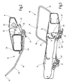
- Fig. 1 eine schematisch vereinfacht und abgebrochen gezeichnete perspektivische Schrägansicht lediglich der wesentlichen Strukturelemente des Sitzbereiches eines Fluggastsitzes, ohne Verkleidungen, Polsterungen, Zusatzeinrichtungen oder dergleichen, versehen mit einem Ausführungsbeispiel des erfindungsgemäßen Komfortsystemes in Form eines Fußnetzes, dargestellt in der Gebrauchsstellung mit im Fußnetz aufgenommenen Fußteilen eines Benutzers;
- Fig. 2 eine Seitenansicht lediglich des Bereiches eines quer verlaufenden Tragholmes der Sitzstruktur von Fig. 1 mit daran angelenkter Festlegeeinrichtung für das Fußnetz gemäß dem Ausführungsbeispiel von Fig. 1 und
- Fig. 3 eine perspektivische Schrägansicht des in Fig. 2 Gezeigten.
- Das erfindungsgemäße Komfortsystem ist in der vorliegenden Beschreibung anhand eines Ausführungsbeispieles erläutert, bei dem ein Abstützteil in Form eines als Ganzes mit 1 bezeichneten Fußnetzes einem Fluggastsitz zugeordnet ist, der Teil einer Reihe von hintereinander angeordneten Sitzen bildet. Genauer gesagt handelt es sich bei dem Sitz von Fig. 1 um einen Sitz, hinter dem sich ein entsprechender weiterer Sitz (nicht gezeigt) befindet, dessen Sitzbenutzer, von dem eine Unterschenkelpartie 3 abgebrochen angedeutet ist, seine Schuhe 5 in das Fußnetz 1 gestellt hat. Wie aus Fig. 1 zu ersehen ist, ist das in der Gebrauchsstellung gezeigte Fußnetz 1 so aufgehängt, dass die Schuhe 5 in dem Fußnetz 1 in geringem Abstand oberhalb des Kabinenbodens 7 aufgenommen sind, wobei sich das Fußnetz 1 aufgrund seiner Flexibilität hängenmattenartig an die Schuhe 5 des Benutzers anschmiegt.
- Wie Fig. 1 zeigt, ist das Fußnetz 1 an seinem vorderen Ende an einer vorderen Endleiste 9 der Sitzstruktur mittels Befestigungsschrauben 11 befestigt, die sich in der Nähe des zugeordneten Seitenrandes des Fußnetzes 1 befinden. Als Träger für das von der Endleiste 9 frei hängende Fußnetz 1, d. h. zum Halten des Fußnetzes 1 in der in Fig. 1 gezeigten Gebrauchsstellung sowie zum Überführen in eine Nicht-Gebrauchsstellung, ist eine Festlegeeinrichtung mit einem bewegbaren Träger vorhanden, an dem das hintere Ende 13 des Fußnetzes 1 aufgehängt ist.
- Die Festlegeeinrichtung weist als beweglichen Träger einen aus rundem Federstahl einstückig gebogenen Bügel 15 auf. Wie Fig. 2 und 3 deutlicher zeigen, ist der Bügel 15 im Umriß U-förmig gestaltet, mit einem geraden, hinteren Quersteg 17 (Fig. 3) und sich an diesem anschließenden, längeren, in Sitzlängsrichtung verlaufenden seitlichen Schenkeln 19, die an Biegestellen 21 und 23 leicht abgebogen sind. Das hintere Ende 13 des Fußnetzes 1 ist am hinteren Quersteg 17 des Bügels 15 mittels einer den entsprechenden Endteil des Bügels 15 aufnehmenden Endtasche 25 des Fußnetzes 1 aufgehängt.
- Die dem Quersteg 17 entgegengesetzten Enden der Schenkel 19 des Bügels 15 sind unterhalb eines quer verlaufenden Tragholmes 29 der Sitzstruktur, gegenüber diesem leicht nach vorn versetzt, an einer Schwenklagerung 27 angelenkt, die für jeden Schenkel 19 eine zur Sitzlängsrichtung quer verlaufende Schwenkachse definiert.
- Fig. 2 und 3 zeigen den Bügel 15 in der an die Unterseite des Sitzes angenäherten Schwenklage, die der Nicht-Gebrauchsstellung entspricht. Aufgrund der an den Biegestellen 21 und 23 leicht gekrümmten Form der Schenkel 19 des Bügels 15 schmiegt sich dieser bei dieser Schwenklage eng an die Unterseite des Sitzes an, so dass das Fußnetz 1 bei der Nicht-Gebrauchsstellung eng an der Unterseite des zugehörigen Sitzes anliegt, somit äußerst geringen Stauraum benötigt und den Fußraum daher im wesentlichen frei läßt. Der Bügel 15 ist in diese Schwenklage durch eine Drehfederanordnung vorgespannt, die an jeder Schwenklagerung 27 eine den Schwenkzapfen umringende Schlingfeder 31 aufweist. Um den Bügel 15 gegen die wirkende Federkraft zu schwenken, um das Fußnetz 1 in die Gebrauchsstellung zu bringen, muß der Benutzer lediglich durch Druck auf das Ende 13 des Fußnetzes 1 und damit auf den Quersteg 17 des Bügels 15 das Fußnetz 1 in die in Fig. 1 gezeigte Lage bringen. Wie lediglich in Fig. 2 und 3 deutlich dargestellt ist, ist an jeder Schwenklagerung 27 dem betreffenden Ende des Schenkels 19 des Bügels 15 eine Rasteinrichtung zugeordnet, die jeweils eine an der Sitzstruktur befestigte Rastscheibe 33 mit Rastvertiefungen 35 aufweist, in die eine federbelastete Rastkugel 37 an einem nur in Fig. 2 und 3 dargestellten Rastarm 39 einrasten kann.
- Die Verrastung kann so ausgelegt sein, dass der Bügel 19 in der in Fig. 1 gezeigten Stellung lösbar verrastet ist, in der sich der Quersteg 17 des Bügels 15 oberhalb des Kabinenbodens 7 befindet, dass durch eine stärkere Krafteinwirkung der Quersteg 17 jedoch bis zum Kabinenboden 7 herab bewegt werden kann, so dass eine Verformung des Bügels 15 bei unsachgemäß starker Krafteinwirkung (beispielsweise durch Vandalismus) vermieden ist.
- Wie Fig. 1 zeigt, ist das Fußnetz 1 mit einer seitlichen Einfassung 41 versehen, die sich von der hinteren Endtasche 25 bis zum vorderen Ende des Fußnetzes 1 an den Befestigungsschrauben 11 erstreckt. Diese Einfassung 41 kann durch elastische Bänder gebildet sein.
- Wie aus den Fig. ersichtlich, erstreckt sich das Fußnetz 1 entsprechend der Form, Größe und Anbringung des Bügels 15 im wesentlichen über die gesamte Breite des Sitzteiles. Die bereits erwähnte Verrastung kann so ausgelegt sein, dass bei in Gebrauchsstellung befindlichem Fußnetz 1 der Benutzer ohne übermäßigen Kraftaufwand, mit den Fußspitzen am hinteren Ende 13 des Fußnetzes 1 angreifend, dieses mit Unterstützung der Kraft der Federn 31 aus der Verrastung lösen kann, so dass die Federn 31 das Fußnetz 1 in die Nicht-Gebrauchsstellung überführen, wo es an der Unterseite des Sitzes verstaut ist.
Claims (11)
- Komfortsystem für einen Sitz, insbesondere für in Reihe hintereinander angeordnete Fahr- und Fluggastsitze, mit mindestens einem Abstützteil (1), das von einer Nicht-Gebrauchsstellung in eine Gebrauchsstellung bringbar ist, bei der Fuß- und Beinteile (3, 5) eines Sitzbenutzers auf zumindest einer Auflagefläche abgestützt sind, wobei das jeweilige Abstützteil (1), mittels einer Festlegeeinrichtung (15) in der Gebrauchsstellung gehalten, sich zumindest teilweise in einem Fußraum erstreckt, der vom Benutzer des hinteren von zwei in Reihe angeordneten Sitzen nutzbar ist, und wobei das Abstützteil (1) in der Nicht-Gebrauchsstellung den Fußraum freigibt, dadurch gekennzeichnet, dass das Abstützteil (1) im wesentlichen flexibel ist und in der Gebrauchsstellung zumindest teilweise einem gekrümmten Verlauf nachfolgt und dass die Festlegeeinrichtung (15) am vorderen der beiden in Reihe angeordneten Sitze angebracht ist.
- Komfortsystem nach Anspruch 1, dadurch gekennzeichnet, dass die Festlegeeinrichtung (15) im vorderen Bereich der Unterseite des zugeordneten Sitzes angebracht ist.
- Komfortsystem nach Anspruch 2, dadurch gekennzeichnet, dass die Festlegeeinrichtung (15) das Abstützteil (1) bei der Nicht-Gebrauchsstellung lösbar in einer an die Unterseite des Sitzes angenäherten Stellung hält.
- Komfortsystem nach Anspruch 3, dadurch gekennzeichnet, dass das Abstützteil (1) zumindest eine bandartige, mindestens einen Teil der Auflagefläche bildende Bahn aufweist.
- Komfortsystem nach Anspruch 4, dadurch gekennzeichnet, dass die Bahn durch ein Gewebe oder Geflecht, vorzugsweise in netzartiger Gestalt (1), aus einem im Hinblick auf Feuersicherheit ausgewählten Material gebildet ist.
- Komfortsystem nach einem der Ansprüche 3 bis 5, dadurch gekennzeichnet, dass das Abstützteil (1) mit seinem vorderen Ende an der Unterseite des zugeordneten Sitzes im vorderem Bereich von dessen Sitzstruktur festgelegt ist.
- Komfortsystem nach Anspruch 6, dadurch gekennzeichnet, dass die Festlegeeinrichtung einen bewegbaren Träger (15) aufweist, der mit seinem einen, vorderen Ende in der Nähe des festgelegten vorderen Endes des Abstützteiles (1) an der Trägerstruktur des Sitzes um eine zur Sitzlängsrichtung senkrechte Schwenkachse schwenkbar gelagert ist und mit seinem von der Schwenklagerung (27) nach hinten auskragenden, hinteren Ende (17) die Aufhängung für den hinteren Rand (13) des Abstützteiles (1) bildet.
- Komfortsystem nach Anspruch 7, dadurch gekennzeichnet, dass der Träger der Festlegeeinrichtung einen im Umriß im wesentlichen U-förmigen Bügel (15) aufweist, an dessen zur Sitzlängsrichtung quer verlaufendem Steg (17) der hintere Rand (13) des beispielsweise als Netz ausgebildeten Abstützteiles (1) befestigt ist und dessen in Längsrichtung entlang der Seitenränder des Abstützteiles (1) verlaufende Schenkel (19) jeweils endseits zur Bildung der Schwenklagerung (27) an der Sitzstruktur angelenkt sind.
- Komfortsystem nach Anspruch 8, dadurch gekennzeichnet, dass eine Federanordnung (31) vorhanden ist, die den Bügel (15) in eine an die Unterseite des Sitzes angenäherte Schwenklage, die der Nicht-Gebrauchsstellung des vorzugsweise als Netz ausgebildeten Abstützteiles (1) entspricht, vorspannt, aus der der Bügel (15) gegen die wirkende Federkraft zum Überführen in die Gebrauchsstellung von der Unterseite des Sitzes wegbewegbar ist.
- Komfortsystem nach Anspruch 9, dadurch gekennzeichnet, dass die Federanordnung je eine jedem Schenkel (19) des Bügels (15) zugeordnete, die Schwenkachse umringende Schlingfeder (31) aufweist.
- Komfortsystem nach einem der Ansprüche 8 bis 10, dadurch gekennzeichnet, dass die Schwenklagerung (27) des Bügels (15) eine Rasteinrichtung (33, 35, 37, 39) aufweist, mittels deren die Schwenkbewegung des Bügels (15) in zumindest einer bevorzugten Schwenklage lösbar verrastbar ist.
Applications Claiming Priority (1)
| Application Number | Priority Date | Filing Date | Title |
|---|---|---|---|
| DE102005015142A DE102005015142A1 (de) | 2005-03-31 | 2005-03-31 | Komfortsystem für einen Sitz, insbesondere für in Reihe hintereinander angeordnete Fahr- und Fluggastsitze |
Publications (2)
| Publication Number | Publication Date |
|---|---|
| EP1707436A1 true EP1707436A1 (de) | 2006-10-04 |
| EP1707436B1 EP1707436B1 (de) | 2009-12-23 |
Family
ID=36570910
Family Applications (1)
| Application Number | Title | Priority Date | Filing Date |
|---|---|---|---|
| EP06003120A Expired - Lifetime EP1707436B1 (de) | 2005-03-31 | 2006-02-16 | Komfortsystem für einen Sitz, insbesondere für in Reihe hintereinander angeordnete Fahr- und Fluggastsitze |
Country Status (4)
| Country | Link |
|---|---|
| US (1) | US7338131B2 (de) |
| EP (1) | EP1707436B1 (de) |
| AT (1) | ATE452789T1 (de) |
| DE (2) | DE102005015142A1 (de) |
Cited By (3)
| Publication number | Priority date | Publication date | Assignee | Title |
|---|---|---|---|---|
| EP3034404A1 (de) * | 2014-12-19 | 2016-06-22 | Recaro Aircraft Seating GmbH & Co. KG | Sitzvorrichtung |
| EP3335931A1 (de) * | 2016-12-19 | 2018-06-20 | Thompson Aero Seating Limited | Ausfahrbare fussstützenanordnung |
| WO2020083514A1 (en) * | 2018-10-25 | 2020-04-30 | Brusa Koltuk Ve Ic Trim Teknolojileri Sanayi Ve Tiaret A.S. | Support seat structure |
Families Citing this family (19)
| Publication number | Priority date | Publication date | Assignee | Title |
|---|---|---|---|---|
| US20060006704A1 (en) * | 2003-12-15 | 2006-01-12 | Be Aerospace, Inc. | Vehicle seating with storage feature |
| DE102006048998A1 (de) * | 2005-12-29 | 2007-07-12 | Airbus Deutschland Gmbh | Teleskopartiges Gepäckfach |
| EP1803645B1 (de) * | 2005-12-29 | 2020-03-11 | Airbus Operations GmbH | Modul für ein Flugzeug |
| DE102006049002B4 (de) * | 2005-12-29 | 2016-02-18 | Airbus Operations Gmbh | Passagiersitz mit einer Gepäckrückhaltevorrichtung |
| DE102007043965B3 (de) * | 2007-09-14 | 2009-02-12 | Autoflug Gmbh | Fußstütze für einen Sicherheitssitz |
| US8702166B2 (en) * | 2008-01-02 | 2014-04-22 | Paul Edward Brunner | Chair support apparatus |
| US20090167063A1 (en) * | 2008-01-02 | 2009-07-02 | Paul Edward Brunner | Chair Apparatus |
| US9227573B2 (en) * | 2010-01-13 | 2016-01-05 | James Daniel Hudspeth | Firearm holster mounting system for vehicles |
| US9796000B2 (en) * | 2011-07-04 | 2017-10-24 | Product Systems Incorporated | Uniform fluid manifold for acoustic transducer |
| US8905483B2 (en) * | 2012-11-12 | 2014-12-09 | Compass Designs LLC | Adjustable footrest |
| DE102013103436B4 (de) * | 2013-04-05 | 2018-10-11 | Recaro Aircraft Seating Gmbh & Co. Kg | Sitzvorrichtung und Sitz, insbesondere Flugzeugsitz, mit einer Sitzvorrichtung |
| US8925740B1 (en) * | 2013-08-15 | 2015-01-06 | John Fanok | Women's footwear storage assembly |
| EP3126235A1 (de) * | 2014-04-04 | 2017-02-08 | B/E Aerospace, Inc. | Flugzeugsitzgrundrahmen |
| US9919803B2 (en) | 2014-04-04 | 2018-03-20 | B/E Aerospace, Inc. | Aircraft seat base frame |
| US10166902B2 (en) * | 2014-05-21 | 2019-01-01 | Jennifer CAYZER | Travel support device |
| WO2019010529A1 (en) * | 2017-07-13 | 2019-01-17 | Jennifer Cayzer | FOLDING SUPPORT DEVICE FOR TRAVEL |
| CN110697053B (zh) * | 2019-09-30 | 2021-06-15 | 湖北航宇嘉泰飞机设备有限公司 | 一种航空旅客座椅脚兜 |
| US12286231B2 (en) * | 2022-07-02 | 2025-04-29 | B/E Aerospace, Inc. | System including stowage pouch |
| GB202308348D0 (en) * | 2023-06-05 | 2023-07-19 | Acro Aircraft Seating Ltd | Footrest |
Citations (4)
| Publication number | Priority date | Publication date | Assignee | Title |
|---|---|---|---|---|
| US5352020A (en) | 1992-07-10 | 1994-10-04 | Weber Aircraft, Inc. | Hydraulic extendable legrest |
| DE10034385A1 (de) * | 2000-07-14 | 2002-01-24 | Marlene Simon | Fußstütze |
| GB2391811A (en) * | 2002-07-27 | 2004-02-18 | Ebrahim Rouholamin | Foot treatment apparatus for reducing the risk of deep vein thrombosis during flying |
| US20040094668A1 (en) * | 2002-11-08 | 2004-05-20 | Alicia Jarosz | Aircraft seat footrest system and method |
Family Cites Families (8)
| Publication number | Priority date | Publication date | Assignee | Title |
|---|---|---|---|---|
| US1389209A (en) * | 1920-02-14 | 1921-08-30 | Samuel L Myatt | Footrest for automobiles |
| US2591598A (en) * | 1949-04-13 | 1952-04-01 | Heywood Wakefield Co | Adjustable footrest |
| US3556590A (en) * | 1968-07-31 | 1971-01-19 | Horace E Harris | Church kneeler with folding legs |
| DE9106107U1 (de) * | 1991-05-17 | 1991-07-25 | Franz Kiel GmbH, 8860 Nördlingen | Fußstütze an in Reihen hintereinander angeordneten Sitzen, insbesondere an Omnibussitzen |
| US5556167A (en) * | 1995-06-30 | 1996-09-17 | Johnson Siemion; Helen F. | Collapsible foot rest for seat backs |
| US6053570A (en) * | 1998-05-21 | 2000-04-25 | Stern; Cindy Jane | Detachable storage device positionable under theater seats |
| US6375266B1 (en) * | 2001-01-18 | 2002-04-23 | Johnson Controls Technology Company | Breakaway footrest |
| US7108329B1 (en) * | 2005-11-15 | 2006-09-19 | Robert Clough | Seating unit with retractable footrest |
-
2005
- 2005-03-31 DE DE102005015142A patent/DE102005015142A1/de not_active Withdrawn
- 2005-08-10 US US11/200,229 patent/US7338131B2/en not_active Expired - Lifetime
-
2006
- 2006-02-16 DE DE502006005709T patent/DE502006005709D1/de not_active Expired - Lifetime
- 2006-02-16 EP EP06003120A patent/EP1707436B1/de not_active Expired - Lifetime
- 2006-02-16 AT AT06003120T patent/ATE452789T1/de active
Patent Citations (4)
| Publication number | Priority date | Publication date | Assignee | Title |
|---|---|---|---|---|
| US5352020A (en) | 1992-07-10 | 1994-10-04 | Weber Aircraft, Inc. | Hydraulic extendable legrest |
| DE10034385A1 (de) * | 2000-07-14 | 2002-01-24 | Marlene Simon | Fußstütze |
| GB2391811A (en) * | 2002-07-27 | 2004-02-18 | Ebrahim Rouholamin | Foot treatment apparatus for reducing the risk of deep vein thrombosis during flying |
| US20040094668A1 (en) * | 2002-11-08 | 2004-05-20 | Alicia Jarosz | Aircraft seat footrest system and method |
Cited By (4)
| Publication number | Priority date | Publication date | Assignee | Title |
|---|---|---|---|---|
| EP3034404A1 (de) * | 2014-12-19 | 2016-06-22 | Recaro Aircraft Seating GmbH & Co. KG | Sitzvorrichtung |
| EP3335931A1 (de) * | 2016-12-19 | 2018-06-20 | Thompson Aero Seating Limited | Ausfahrbare fussstützenanordnung |
| US10543920B2 (en) | 2016-12-19 | 2020-01-28 | Thompson Aero Seating Limited | Deployable foot rest assembly |
| WO2020083514A1 (en) * | 2018-10-25 | 2020-04-30 | Brusa Koltuk Ve Ic Trim Teknolojileri Sanayi Ve Tiaret A.S. | Support seat structure |
Also Published As
| Publication number | Publication date |
|---|---|
| DE502006005709D1 (de) | 2010-02-04 |
| ATE452789T1 (de) | 2010-01-15 |
| DE102005015142A1 (de) | 2006-10-05 |
| EP1707436B1 (de) | 2009-12-23 |
| US7338131B2 (en) | 2008-03-04 |
| US20060238012A1 (en) | 2006-10-26 |
Similar Documents
| Publication | Publication Date | Title |
|---|---|---|
| EP1707436A1 (de) | Komfortsystem für einen Sitz, insbesondere für in Reihe hintereinander angeordnete Fahr- und Fluggastsitze | |
| DE102007061329B4 (de) | Fahrzeugsitz mit Sitztiefenverstelleinrichtung | |
| DE69304145T2 (de) | Sitz und seine Verwendung in einem Fahrzeug | |
| DE102008006019B4 (de) | Kraftfahrzeugsitz mit einem Sitzbereich | |
| DE102016218728B4 (de) | Fahrzeugsitz | |
| EP2719304B1 (de) | Bürostuhl mit Rückenlehnenanordnung | |
| DE2911027A1 (de) | Sitz, insbesondere fuer oeffentliche transportfahrzeuge | |
| DE2607192A1 (de) | Bestuhlung fuer verkehrsmittel, insbesondere omnibusse | |
| EP1789317B1 (de) | Sitz, insbesondere fluggastsitz | |
| DE102007063565A1 (de) | Kraftfahrzeugsitz | |
| EP1695909A1 (de) | Fahrgastsitz, insbesondere Fluggastsitz | |
| DE102006043633B4 (de) | Klappbarer Fahrzeugsitz | |
| DE1429333A1 (de) | Sitz | |
| DE102018122906A1 (de) | Rückenlehne, insbesondere für einen Sitz | |
| DE102008017711B4 (de) | Kraftfahrzeugsitz mit einem Befestigungsmittel zur Befestigung eines Kindersitzes und Sitzanordnung mit einem solchen Kraftfahrzeugsitz | |
| DE112008004026B4 (de) | Fahrzeugsitz-Baugruppe mit selbsteinstellendem Sitzpolster | |
| DE102004027900B4 (de) | Fahrzeugsitz | |
| EP3843588B1 (de) | Rückenlehne, insbesondere für einen sitz | |
| DE3418233C2 (de) | ||
| DE4232364C2 (de) | Schalensitz für Fahrzeuge, insbesondere für Personenkraftwagen | |
| DE102004050730B4 (de) | Flexibles Abstützteil für in Reihe hintereinander angeordnete Fahr- und Fluggastsitze | |
| WO2007082686A2 (de) | Fahrzeugsitz mit integriertem kindersitz | |
| DE202012104761U1 (de) | Rückenlehnenanordnung | |
| WO2008037754A2 (de) | Sitzlehne für ein kraftfahrzeug sowie kraftfahrzeugsitz | |
| DE102018121143A1 (de) | Rückenlehne, insbesondere für einen Sitz |
Legal Events
| Date | Code | Title | Description |
|---|---|---|---|
| PUAI | Public reference made under article 153(3) epc to a published international application that has entered the european phase |
Free format text: ORIGINAL CODE: 0009012 |
|
| 17P | Request for examination filed |
Effective date: 20060803 |
|
| AK | Designated contracting states |
Kind code of ref document: A1 Designated state(s): AT BE BG CH CY CZ DE DK EE ES FI FR GB GR HU IE IS IT LI LT LU LV MC NL PL PT RO SE SI SK TR |
|
| AX | Request for extension of the european patent |
Extension state: AL BA HR MK YU |
|
| 17Q | First examination report despatched |
Effective date: 20061124 |
|
| AKX | Designation fees paid |
Designated state(s): AT BE BG CH CY CZ DE DK EE ES FI FR GB GR HU IE IS IT LI LT LU LV MC NL PL PT RO SE SI SK TR |
|
| GRAP | Despatch of communication of intention to grant a patent |
Free format text: ORIGINAL CODE: EPIDOSNIGR1 |
|
| GRAS | Grant fee paid |
Free format text: ORIGINAL CODE: EPIDOSNIGR3 |
|
| GRAA | (expected) grant |
Free format text: ORIGINAL CODE: 0009210 |
|
| AK | Designated contracting states |
Kind code of ref document: B1 Designated state(s): AT BE BG CH CY CZ DE DK EE ES FI FR GB GR HU IE IS IT LI LT LU LV MC NL PL PT RO SE SI SK TR |
|
| REG | Reference to a national code |
Ref country code: GB Ref legal event code: FG4D Free format text: NOT ENGLISH |
|
| REG | Reference to a national code |
Ref country code: CH Ref legal event code: EP |
|
| REG | Reference to a national code |
Ref country code: IE Ref legal event code: FG4D |
|
| REF | Corresponds to: |
Ref document number: 502006005709 Country of ref document: DE Date of ref document: 20100204 Kind code of ref document: P |
|
| REG | Reference to a national code |
Ref country code: NL Ref legal event code: VDEP Effective date: 20091223 |
|
| PG25 | Lapsed in a contracting state [announced via postgrant information from national office to epo] |
Ref country code: SE Free format text: LAPSE BECAUSE OF FAILURE TO SUBMIT A TRANSLATION OF THE DESCRIPTION OR TO PAY THE FEE WITHIN THE PRESCRIBED TIME-LIMIT Effective date: 20091223 Ref country code: LT Free format text: LAPSE BECAUSE OF FAILURE TO SUBMIT A TRANSLATION OF THE DESCRIPTION OR TO PAY THE FEE WITHIN THE PRESCRIBED TIME-LIMIT Effective date: 20091223 Ref country code: FI Free format text: LAPSE BECAUSE OF FAILURE TO SUBMIT A TRANSLATION OF THE DESCRIPTION OR TO PAY THE FEE WITHIN THE PRESCRIBED TIME-LIMIT Effective date: 20091223 |
|
| LTIE | Lt: invalidation of european patent or patent extension |
Effective date: 20091223 |
|
| PG25 | Lapsed in a contracting state [announced via postgrant information from national office to epo] |
Ref country code: SI Free format text: LAPSE BECAUSE OF FAILURE TO SUBMIT A TRANSLATION OF THE DESCRIPTION OR TO PAY THE FEE WITHIN THE PRESCRIBED TIME-LIMIT Effective date: 20091223 Ref country code: PL Free format text: LAPSE BECAUSE OF FAILURE TO SUBMIT A TRANSLATION OF THE DESCRIPTION OR TO PAY THE FEE WITHIN THE PRESCRIBED TIME-LIMIT Effective date: 20091223 Ref country code: LV Free format text: LAPSE BECAUSE OF FAILURE TO SUBMIT A TRANSLATION OF THE DESCRIPTION OR TO PAY THE FEE WITHIN THE PRESCRIBED TIME-LIMIT Effective date: 20091223 |
|
| REG | Reference to a national code |
Ref country code: IE Ref legal event code: FD4D |
|
| PG25 | Lapsed in a contracting state [announced via postgrant information from national office to epo] |
Ref country code: EE Free format text: LAPSE BECAUSE OF FAILURE TO SUBMIT A TRANSLATION OF THE DESCRIPTION OR TO PAY THE FEE WITHIN THE PRESCRIBED TIME-LIMIT Effective date: 20091223 Ref country code: RO Free format text: LAPSE BECAUSE OF FAILURE TO SUBMIT A TRANSLATION OF THE DESCRIPTION OR TO PAY THE FEE WITHIN THE PRESCRIBED TIME-LIMIT Effective date: 20091223 Ref country code: IS Free format text: LAPSE BECAUSE OF FAILURE TO SUBMIT A TRANSLATION OF THE DESCRIPTION OR TO PAY THE FEE WITHIN THE PRESCRIBED TIME-LIMIT Effective date: 20100423 Ref country code: NL Free format text: LAPSE BECAUSE OF FAILURE TO SUBMIT A TRANSLATION OF THE DESCRIPTION OR TO PAY THE FEE WITHIN THE PRESCRIBED TIME-LIMIT Effective date: 20091223 Ref country code: ES Free format text: LAPSE BECAUSE OF FAILURE TO SUBMIT A TRANSLATION OF THE DESCRIPTION OR TO PAY THE FEE WITHIN THE PRESCRIBED TIME-LIMIT Effective date: 20100403 Ref country code: PT Free format text: LAPSE BECAUSE OF FAILURE TO SUBMIT A TRANSLATION OF THE DESCRIPTION OR TO PAY THE FEE WITHIN THE PRESCRIBED TIME-LIMIT Effective date: 20100423 Ref country code: BG Free format text: LAPSE BECAUSE OF FAILURE TO SUBMIT A TRANSLATION OF THE DESCRIPTION OR TO PAY THE FEE WITHIN THE PRESCRIBED TIME-LIMIT Effective date: 20100323 |
|
| BERE | Be: lapsed |
Owner name: RECARO AIRCRAFT SEATING G.M.B.H. & CO. KG Effective date: 20100228 |
|
| PG25 | Lapsed in a contracting state [announced via postgrant information from national office to epo] |
Ref country code: CZ Free format text: LAPSE BECAUSE OF FAILURE TO SUBMIT A TRANSLATION OF THE DESCRIPTION OR TO PAY THE FEE WITHIN THE PRESCRIBED TIME-LIMIT Effective date: 20091223 Ref country code: SK Free format text: LAPSE BECAUSE OF FAILURE TO SUBMIT A TRANSLATION OF THE DESCRIPTION OR TO PAY THE FEE WITHIN THE PRESCRIBED TIME-LIMIT Effective date: 20091223 |
|
| REG | Reference to a national code |
Ref country code: CH Ref legal event code: PL |
|
| PG25 | Lapsed in a contracting state [announced via postgrant information from national office to epo] |
Ref country code: GR Free format text: LAPSE BECAUSE OF FAILURE TO SUBMIT A TRANSLATION OF THE DESCRIPTION OR TO PAY THE FEE WITHIN THE PRESCRIBED TIME-LIMIT Effective date: 20100324 Ref country code: CH Free format text: LAPSE BECAUSE OF NON-PAYMENT OF DUE FEES Effective date: 20100228 Ref country code: MC Free format text: LAPSE BECAUSE OF NON-PAYMENT OF DUE FEES Effective date: 20100301 Ref country code: CY Free format text: LAPSE BECAUSE OF FAILURE TO SUBMIT A TRANSLATION OF THE DESCRIPTION OR TO PAY THE FEE WITHIN THE PRESCRIBED TIME-LIMIT Effective date: 20091223 Ref country code: LI Free format text: LAPSE BECAUSE OF NON-PAYMENT OF DUE FEES Effective date: 20100228 Ref country code: IE Free format text: LAPSE BECAUSE OF FAILURE TO SUBMIT A TRANSLATION OF THE DESCRIPTION OR TO PAY THE FEE WITHIN THE PRESCRIBED TIME-LIMIT Effective date: 20091223 |
|
| PLBE | No opposition filed within time limit |
Free format text: ORIGINAL CODE: 0009261 |
|
| STAA | Information on the status of an ep patent application or granted ep patent |
Free format text: STATUS: NO OPPOSITION FILED WITHIN TIME LIMIT |
|
| 26N | No opposition filed |
Effective date: 20100924 |
|
| PG25 | Lapsed in a contracting state [announced via postgrant information from national office to epo] |
Ref country code: DK Free format text: LAPSE BECAUSE OF FAILURE TO SUBMIT A TRANSLATION OF THE DESCRIPTION OR TO PAY THE FEE WITHIN THE PRESCRIBED TIME-LIMIT Effective date: 20091223 |
|
| PG25 | Lapsed in a contracting state [announced via postgrant information from national office to epo] |
Ref country code: BE Free format text: LAPSE BECAUSE OF NON-PAYMENT OF DUE FEES Effective date: 20100228 |
|
| PG25 | Lapsed in a contracting state [announced via postgrant information from national office to epo] |
Ref country code: LU Free format text: LAPSE BECAUSE OF NON-PAYMENT OF DUE FEES Effective date: 20100216 Ref country code: HU Free format text: LAPSE BECAUSE OF FAILURE TO SUBMIT A TRANSLATION OF THE DESCRIPTION OR TO PAY THE FEE WITHIN THE PRESCRIBED TIME-LIMIT Effective date: 20100624 |
|
| PG25 | Lapsed in a contracting state [announced via postgrant information from national office to epo] |
Ref country code: TR Free format text: LAPSE BECAUSE OF FAILURE TO SUBMIT A TRANSLATION OF THE DESCRIPTION OR TO PAY THE FEE WITHIN THE PRESCRIBED TIME-LIMIT Effective date: 20091223 |
|
| REG | Reference to a national code |
Ref country code: AT Ref legal event code: MM01 Ref document number: 452789 Country of ref document: AT Kind code of ref document: T Effective date: 20110216 |
|
| PG25 | Lapsed in a contracting state [announced via postgrant information from national office to epo] |
Ref country code: AT Free format text: LAPSE BECAUSE OF NON-PAYMENT OF DUE FEES Effective date: 20110216 |
|
| REG | Reference to a national code |
Ref country code: FR Ref legal event code: PLFP Year of fee payment: 11 |
|
| REG | Reference to a national code |
Ref country code: FR Ref legal event code: PLFP Year of fee payment: 12 |
|
| REG | Reference to a national code |
Ref country code: FR Ref legal event code: PLFP Year of fee payment: 13 |
|
| PGFP | Annual fee paid to national office [announced via postgrant information from national office to epo] |
Ref country code: IT Payment date: 20190222 Year of fee payment: 14 Ref country code: DE Payment date: 20190219 Year of fee payment: 14 Ref country code: GB Payment date: 20190221 Year of fee payment: 14 |
|
| PGFP | Annual fee paid to national office [announced via postgrant information from national office to epo] |
Ref country code: FR Payment date: 20190221 Year of fee payment: 14 |
|
| REG | Reference to a national code |
Ref country code: DE Ref legal event code: R119 Ref document number: 502006005709 Country of ref document: DE |
|
| GBPC | Gb: european patent ceased through non-payment of renewal fee |
Effective date: 20200216 |
|
| PG25 | Lapsed in a contracting state [announced via postgrant information from national office to epo] |
Ref country code: FR Free format text: LAPSE BECAUSE OF NON-PAYMENT OF DUE FEES Effective date: 20200229 Ref country code: GB Free format text: LAPSE BECAUSE OF NON-PAYMENT OF DUE FEES Effective date: 20200216 Ref country code: DE Free format text: LAPSE BECAUSE OF NON-PAYMENT OF DUE FEES Effective date: 20200901 |
|
| PG25 | Lapsed in a contracting state [announced via postgrant information from national office to epo] |
Ref country code: IT Free format text: LAPSE BECAUSE OF NON-PAYMENT OF DUE FEES Effective date: 20200216 |