EP1707250B1 - Kinderspielfahrzeug - Google Patents
Kinderspielfahrzeug Download PDFInfo
- Publication number
- EP1707250B1 EP1707250B1 EP05007227A EP05007227A EP1707250B1 EP 1707250 B1 EP1707250 B1 EP 1707250B1 EP 05007227 A EP05007227 A EP 05007227A EP 05007227 A EP05007227 A EP 05007227A EP 1707250 B1 EP1707250 B1 EP 1707250B1
- Authority
- EP
- European Patent Office
- Prior art keywords
- child
- toy vehicle
- retaining
- actuating element
- arm
- Prior art date
- Legal status (The legal status is an assumption and is not a legal conclusion. Google has not performed a legal analysis and makes no representation as to the accuracy of the status listed.)
- Expired - Lifetime
Links
- 210000000078 claw Anatomy 0.000 claims description 8
- 230000003213 activating effect Effects 0.000 abstract 4
- 239000002023 wood Substances 0.000 description 6
- 239000002184 metal Substances 0.000 description 3
- 230000005484 gravity Effects 0.000 description 2
- 238000001746 injection moulding Methods 0.000 description 2
- 238000011161 development Methods 0.000 description 1
- 230000018109 developmental process Effects 0.000 description 1
Images


Classifications
-
- A—HUMAN NECESSITIES
- A63—SPORTS; GAMES; AMUSEMENTS
- A63H—TOYS, e.g. TOPS, DOLLS, HOOPS OR BUILDING BLOCKS
- A63H17/00—Toy vehicles, e.g. with self-drive; ; Cranes, winches or the like; Accessories therefor
- A63H17/12—Toy vehicles, e.g. with self-drive; ; Cranes, winches or the like; Accessories therefor with cranes, winches or the like
Definitions
- the invention relates to a children's vehicle with two parallel juxtaposed, interconnected, pivotable support arms, at the free end a charger is attached, wherein the support arms are locked in a raised position of the charger to the vehicle body and releasing the lock the charger in a lowered Move position.
- Toy vehicles of this type have a high play value for children because they can carry objects with the charger from one place to another.
- the charger is placed at the point where wood pieces are, for example, in a lowered loading position in which the charger picks up the pieces of wood or the like, whereupon the charger is lifted and locked in this state to the vehicle. Subsequently, the cargo is transported to its destination where it is deposited.
- EP-A-0 783 906 For example, a children's vehicle is known.
- the present invention has for its object to provide a toy vehicle of the type mentioned above, which has a charger for gripping preferably elongated objects such as pieces of wood, and which is easily and reliably operated by a child by hand.
- the charger is a fork gripper having two interconnected by a joint means Gabelgreiferhuggn, each pivotally connected to the support arms of the children's toy vehicle, and that one of the support arms has a provided with a handle rod-shaped actuator which along the Retaining arm is reciprocable and is connected at its end to the fork gripper in the region of the hinge device, so that the feed of the actuating element, the fork gripper halves are opened and moved when retracting the actuating element in the closed position.
- the children's toy vehicle according to the invention is thus suitable for loading preferably elongate objects such as pieces of wood, wherein the fork gripper is to be opened and closed in a simple manner by a child by advancing and retracting the rod-shaped actuating element.
- the support arms are articulated on both sides of the engine block of the children's toy vehicle, where also the locking mechanism, with which the retaining arms are fixable in the raised position, is provided.
- each support arm which is adapted to engage over a pin projecting laterally from the engine block
- the support arms connected together in one unit move downwardly by gravity until the fork gripper rests on the ground, whereupon the fork gripper is moved by advancing the actuating element in the open position.
- This can also be done before lowering the retaining arms.
- the children's vehicle especially by means of a pedal drive, but also a motor drive can be provided - are driven so that the lower fork gripper half engages a male wood or the like, whereupon the rod-shaped actuator is retracted by his handle, causing the fork gripper as far as closes, as the charge allows.
- the holding arms are preferably in the raised position by means of the handle of the rod-shaped actuating element and a further handle, which is fixedly attached to the other holding arm pulled up, in which the claw-shaped locking elements of the two retaining arms engage over the laterally projecting axle stub or pins and record in their interior, whereby the support arms are locked automatically with the loaded fork gripper in the raised position.
- the cargo is then driven to its destination, where it is stored by opening the fork gripper by means of the actuating element and optionally by lowering the holding arms again.
- the holding arms have a preferably elongated, substantially rectilinear central portion and in each case two downwardly angled end portions.
- the support arms are connected together in the region of their free end by a transverse arm to a rigid unit, wherein the transverse arm is preferably pivotally mounted at the upper ends of the front, of the central portions obliquely forward and downward end portions of the support arms.
- This cross arm is pivotally connected to the upper fork gripper half, preferably by a hinge which is arranged on a central, forward-facing approach of the cross arm and the upper half of the upper half of the fork grip hingedly.
- the lower fork gripper half is preferably articulated to the lower ends of the front end portions of the support arms.
- the actuating element for opening and closing the fork gripper is preferably guided in the longitudinal direction of the middle portion of the associated, preferably right holding arm and protrudes forward from the holding arm, where the actuating element has a transverse to the support arms, ie in the direction of the cross arm end portion of the the lower fork gripper half is attached.
- the transverse end section preferably engages through webs integrally formed on the rear side of the lower fork gripper half and provided with corresponding holes. These aligned holes are located below the hinge device that connects the two fork gripper halves.
- the handle connected to the actuating element which preferably extends approximately at right angles to the actuating element, is guided in a slot of the holding arm, so that the actuating element can also be easily moved forward and backward by a child.
- the actuator is preferably a rod made of metal.
- the actuating element is preferably formed integrally with the angled handle and the likewise angled end portion.
- the handle immovably attached to the other support arm preferably has the same shape as the handle of the actuator and is secured to the location coincident with the retracted position of the other handle.
- the two handles preferably connect with the central portion of the support arms at an angle of about 90 ° and are each provided at its free end with a spherical knob.
- the fork gripper is preferably made of a hard plastic and is manufactured by injection molding.
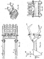
- the support arms 1 and 2 are attached to the outer sides of the engine block of a children's toy tractor, not shown.
- the two holding arms are pivotally mounted on the side of the engine block projecting axle stubs, which are indicated in Figures 1C to 3C by the reference numeral 3.
- the support arms are locked in a raised position by means of limited pivoting jaws 4, which also grip laterally from the engine block protruding (not shown) rod-shaped brackets from above.
- the jaws 4 can be pivoted so that they get out of engagement with the brackets, so that the support arms are lowered 1,2 with the attached in the region of their free ends fork gripper 5 by gravity to the ground.
- the holding arms 1, 2 each have a central portion 6, which may consist of two rod-shaped elements, and downwardly angled end portions 7 and 8. These portions are assembled into a rigid unit.
- the support arms 1, 2 are connected to each other by means of a transverse arm 9, so that they form a frame-shaped unit.
- the transverse arm 9 is fixed by hinge-like joints 10 to the support arms 1.2.
- the fork gripper 5 consists of an upper fork gripper half 11 and a lower fork gripper half 12 which are interconnected by a hinge-like hinge device 13 also.
- the upper fork gripper half 11 is articulated centrally on the transverse arm 9.
- the upper fork gripper half 11 has a rear projection 14 with a bore which is aligned with corresponding holes by two parallel spaced webs 1 5, through which a pin extends as a hinge axis.
- This upper joint is identified by the reference numeral 16.
- the lower fork gripper half 12 is articulated at its two lateral ends in each case at the lower end of the end sections 8 of the retaining arms 1, 2. These hinge-like joints are denoted by the reference numeral 17.
- a handle 18 upwards which is provided at its free end with a spherical knob 19.
- the handle 18 formed by a metal rod passes through a slot in the upper wall of the support arm 2 in the interior thereof and is there angled so that it passes through the central portion 6, said rod-shaped actuator 20 front of the downwardly angled end portion. 8 of the support arm 2 exits and there is angled first downwards and then transversely to the plane of the support arms. In this case, passes through the parallel to the transverse arm 9 extending, angled end portion of the rod-shaped actuating element 20 holes of webs, which are integrally formed on the back of the lower fork gripper half 12. These holes are in the representation of Figure 1C approximately vertically below the hinge means 13 of the two fork gripper halves 11, 12th
- the handle 18 of the actuating element 20 is located at the rear end of the elongated hole 20a.
- the actuator 20 is advanced accordingly, opens the fork gripper 5 in the intermediate opening position shown in Figure 2.
- the fork gripper opens completely, as Figure 3 shows.
- the other support arm 1 is also provided with a handle 21 with a spherical knob 22.
- This handle 21 is immovably attached to the support arm 1 and is used together with the other handle 18 to raise the lowered support arms with the fork gripper from the ground so that the entire assembly is locked again by the claws 4 in the raised position on the vehicle, so that the vehicle can be moved by means of a crank or with motor power to the point at the example of the fork gripper recorded wood pieces are to be stored.
- the fork gripper is made of plastic and is manufactured by injection molding.
- the rod-shaped actuating element 20 preferably consists together with the handle 18 of a metal rod.
Landscapes
- Toys (AREA)
- Materials For Medical Uses (AREA)
- Medicines Containing Plant Substances (AREA)
- Vehicle Interior And Exterior Ornaments, Soundproofing, And Insulation (AREA)
- Road Signs Or Road Markings (AREA)
Description
- Die Erfindung betrifft ein Kinderspielfahrzeug mit zwei parallel nebeneinander verlaufenden, miteinander verbundenen, schwenkbaren Haltearmen, an deren freien Endbereich ein Ladegerät befestigt ist, wobei die Haltearme in einer angehobenen Position des Ladegerätes an dem Fahrzeugkörper verriegelbar sind und bei Freigabe der Verriegelung das Ladegerät in eine abgesenkte Position bewegen.
- Spielfahrzeuge dieser Art haben für Kinder einen hohen Spielwert, da sie mit dem Ladegerät Gegenstände von einer Stelle zur anderen transportieren können. Dazu wird das Ladegerät an der Stelle, an der sich beispielsweise Holzstücke befinden, in eine abgesenkte Ladeposition gebracht, in der das Ladegerät die Holzstücke oder dergleichen aufnimmt, woraufhin das Ladegerät angehoben und in diesem Zustand an dem Fahrzeug verriegelt wird. Anschließend wird die Ladung zu ihrem Bestimmungsort transportiert, an dem sie abgelegt wird.
- Aus
EP-A-0 783 906 ist zum Beispiel ein Kinderspielfahrzeug bekannt. - Der vorliegenden Erfindung liegt die Aufgabe zugrunde, ein Spielfahrzeug der eingangs genannten Art anzugeben, das ein Ladegerät zum Greifen von bevorzugt langgestreckten Gegenständen wie Holzstücke hat, und das von einem Kind einfach und zuverlässig von Hand bedienbar ist.
- Diese Aufgabe wird erfindungsgemäß durch die Merkmale des Patentanspruchs 1 gelöst.
- Vorteilhafte Weiterbildungen der Erfindung sind in den Unteransprüchen gekennzeichnet.
- Die Erfindung sieht vor, daß das Ladegerät ein Gabelgreifer ist, der zwei durch eine Gelenkeinrichtung miteinander verbundene Gabelgreiferhälften aufweist, die jeweils schwenkbar mit den Haltearmen des Kinderspielfahrzeugs verbunden sind, und daß einer der Haltearme ein mit einem Handgriff versehenes stabförmiges Betätigungselement aufweist, das entlang des Haltearms hin- und herbewegbar ist und an seinem Endbereich mit dem Gabelgreifer im Bereich der Gelenkeinrichtung verbunden ist, so daß beim Vorschub des Betätigungselementes die Gabelgreiferhälften geöffnet und beim Zurückziehen des Betätigungselementes in Richtung der Schließstellung bewegt werden.
- Das erfindungsgemäße Kinderspielfahrzeug ist damit zum Laden von bevorzugt langgestreckten Gegenständen wie Holzstücken geeignet, wobei der Gabelgreifer auf einfache Weise von einem Kind durch Vorschieben und Zurückziehen des stabförmigen Betätigungselementes zu öffnen und zu schließen ist. Die Haltearme sind dabei an beiden Seiten des Motorblocks des Kinderspielfahrzeugs angelenkt, wo auch der Verriegelungsmechanismus, mit dem die Haltearme in der angehobenen Position fixierbar sind, vorgesehen ist. Wenn der Verriegelungsmechanismus, vorzugsweise eine an jedem Haltearm vorgesehene Klaue, die einen vom Motorblock seitlich vorstehenden Zapfen übergreifen kann, freigegeben wird, bewegen sich die miteinander zu einer Einheit verbundenen Haltearme infolge Schwerkraft nach unten, bis der Gabelgreifer auf dem Boden aufliegt, woraufhin der Gabelgreifer durch Vorschub des Betätigungselementes in die Öffnungsstellung bewegt wird. Dies kann auch vor dem Absenken der Haltearme erfolgen. Anschließend kann das Kinderspielfahrzeug - insbesondere mittels eines Tretantriebs, an dessen Stelle aber auch ein Motorantrieb vorgesehen sein kann - so vorgefahren werden, daß die untere Gabelgreiferhälfte einen aufzunehmenden Holzstapel oder dergleichen untergreift, woraufhin das stabförmige Betätigungselement mittels seines Handgriffs zurückgezogen wird, wodurch sich der Gabelgreifer soweit schließt, wie dies die Ladung zuläßt.
- Anschließend werden die Haltearme bevorzugt mittels des Handgriffs des stabförmigen Betätigungselementes und eines weiteren Handgriffs, der an dem anderen Haltearm feststehend angebracht ist, in die angehobene Position hochgezogen, in der die klauenförmigen Verriegelungselemente der beiden Haltearme die seitlich vorstehenden Achsstummel bzw. Stifte übergreifen und in ihren Innenraum aufnehmen, wodurch die Haltearme mit dem beladenen Gabelgreifer in der angehobenen Stellung selbständig verriegelt werden. In diesem Zustand wird die Ladung dann zu ihrem Bestimmungsort gefahren, wo sie durch Öffnen des Gabelgreifers mittels des Betätigungselementes und gegebenenfalls durch erneutes Absenken der Haltearme abgelegt wird.
- In weiterer Ausgestaltung der Erfindung ist vorgesehen, daß die Haltearme einen bevorzugt langgestreckten, im wesentlichen geradlinigen mittleren Abschnitt und jeweils zwei nach unten abgewinkelte Endabschnitte aufweisen. Die Haltearme sind im Bereich ihres freien Endes durch einen Querarm zu einer starren Einheit miteinander verbunden, wobei der Querarm bevorzugt an den oberen Enden der vorderen, von dem mittleren Abschnitten schräg nach vorne und unten weisenden Endabschnitten der Haltearme schwenkbar angebracht ist. Dieser Querarm ist gelenkig mit der oberen Gabelgreiferhälfte verbunden, vorzugsweise durch ein Gelenk, das an einem mittigen, nach vorne weisenden Ansatz des Querarms angeordnet ist und die obere Gabelgreiferhälfte in deren Mitte scharnierartig gelenkig hält.
- Die untere Gabelgreiferhälfte ist bevorzugt an den unteren Enden der vorderen Endabschnitte der Haltearme angelenkt.
- Das Betätigungselement zum Öffnen und Schließen des Gabelgreifers ist bevorzugt in Längsrichtung des mittleren Abschnitts des zugehörigen, bevorzugt rechten Haltearms geführt und ragt vorne aus dem Haltearm heraus, wo das Betätigungselement einen quer zu den Haltearmen, d.h. in Richtung des Querarms verlaufenden Endabschnitt aufweist, der an der unteren Gabelgreiferhälfte befestigt ist. Der querverlaufende Endabschnitt durchgreift dabei bevorzugt an der Rückseite der unteren Gabelgreiferhälfte angeformte Stege, die mit entsprechenden Löchern versehen sind. Diese miteinander fluchtende Löcher befinden sich unterhalb der Gelenkeinrichtung, die die beiden Gabelgreiferhälften verbindet.
- Der mit dem Betätigungselement verbundene Handgriff, der bevorzugt etwa rechtwinklig zu dem Betätigungselement verläuft, ist in einem Langloch des Haltearms geführt, so daß das Betätigungselement auch von einem Kind leicht vorwärts und rückwärts bewegt werden kann. Das Betätigungselement ist bevorzugt eine Stange, die aus Metall besteht. Das Betätigungselement ist bevorzugt einstückig mit dem abgewinkelten Handgriff und dem ebenfalls abgewinkelten Endabschnitt ausgebildet.
- Der an dem anderen Haltearm unbeweglich angebrachte Handgriff hat bevorzugt dieselbe Form wie der Handgriff des Betätigungselementes und ist an der mit der zurückgezogenen Position des anderes Handgriffs übereinstimmenden Stelle befestigt. Die beiden Handgriffe schließen mit dem mittleren Abschnitt der Haltearme bevorzugt einen Winkel von etwa 90° ein und sind an ihrem freien Ende jeweils mit einem kugelförmigen Knopf versehen.
- Der Gabelgreifer besteht bevorzugt aus einem harten Kunststoff und ist im Spritzgußverfahren hergestellt.
- Weitere Einzelheiten der Erfindung ergeben sich aus der nachfolgenden Beschreibung einer bevorzugten Ausführungsform der Haltearme und des Gabelgreifers, wobei das zugehörige Kinderspielfahrzeug nicht dargestellt ist.
- Die Figuren zeigen:
- Figuren 1 A bis 1 D
- die Haltearme mit dem Gabelgreifer in der geschlossenen Position in einer perspektivischen Ansicht, einer Vorderansicht, einer Seitenansicht und einer Aufsicht;
- Figuren 2A bis 2D
- die Anordnung gemäß Figur 1 im leicht geöffneten Zustand des Gabelgreifers und
- Figuren 3A bis 4D
- die Anordnung gemäß Figur 1 im vollständig geöffneten Zustand des Gabelgreifers.
- Die Haltearme 1 und 2 sind an den Außenseiten des Motorblocks eines nicht dargestellten Kinderspieltraktors befestigt. Die beiden Haltearme sitzen schwenkbar auf seitlich von dem Motorblock abstehenden Achsstummeln, die in den Figuren 1C bis 3C durch das Bezugszeichen 3 angedeutet sind. Die Haltearme sind in einer angehobenen Position mittels begrenzt schwenkbarer Klauen 4 verriegelbar, die ebenfalls seitlich von dem Motorblock abstehende (nicht dargestellte) stabförmige Halterungen von oben ergreifen. Durch einen hier nicht interessierenden Mechanismus können die Klauen 4 so hochgeschwenkt werden, daß sie außer Eingriff mit den Halterungen geraten, so daß die Haltearme 1,2 mit dem im Bereich ihrer freien Enden befestigten Gabelgreifer 5 durch Schwerkraft zum Boden abgesenkt werden.
- Die Haltearme 1,2 haben jeweils einen mittleren Abschnitt 6, der aus zwei stabförmigen Elementen bestehen kann, und nach unten abgewinkelte Endabschnitte 7 und 8. Diese Abschnitte sind zu einer starren Einheit zusammengesetzt.
- Außerdem sind die Haltearme 1, 2 mittels eines Querarms 9 miteinander verbunden, so daß sie eine rahmenförmige Einheit bilden. Der Querarm 9 ist durch scharnierartige Gelenke 10 an den Haltearmen 1,2 befestigt.
- Der Gabelgreifer 5 besteht aus einer oberen Gabelgreiferhälfte 11 und einer unteren Gabelgreiferhälfte 12, die durch eine ebenfalls scharnierartige Gelenkeinrichtung 13 miteinander verbunden sind.
- Die obere Gabelgreiferhälfte 11 ist mittig an dem Querarm 9 angelenkt. Hierzu hat die obere Gabelgreiferhälfte 11 einen rückwärtigen Ansatz 14 mit einer Bohrung, die mit entsprechenden Bohrungen durch zwei parallel voneinander beabstandeten Stegen 1 5 fluchtet, durch die ein Stift als Gelenkachse verläuft. Dieses obere Gelenk ist mit dem Bezugszeichen 16 gekennzeichnet.
- Die untere Gabelgreiferhälfte 12 ist an ihren beiden seitlichen Enden jeweils am unteren Ende der Endabschnitte 8 der Haltearme 1,2 angelenkt. Diese ebenfalls scharnierartigen Gelenke sind mit dem Bezugszeichen 17 bezeichnet.
- Von dem rechten Haltearm 2 steht ein Handgriff 18 nach oben vor, der an seinem freien Ende mit einem kugelförmigen Knopf 19 versehen ist. Der durch einen Metallstab gebildete Handgriff 18 tritt durch ein Langloch in der oberen Wand des Haltearms 2 in dessen Innenraum ein und ist dort so abgewinkelt, daß er durch den mittleren Abschnitt 6 verläuft, wobei dieses stabförmige Betätigungselement 20 vorne aus dem nach unten abgewinkelten Endabschnitt 8 des Haltearms 2 austritt und dort zunächst nach unten und dann quer zur Ebene der Haltearme abgewinkelt ist. Dabei durchgreift der parallel zu dem Querarm 9 verlaufende, abgewinkelte Endabschnitt des stabförmigen Betätigungselementes 20 Bohrungen von Stegen, die an der Rückseite der unteren Gabelgreiferhälfte 12 angeformt sind. Diese Bohrungen liegen in der Darstellung der Figur 1C etwa vertikal unterhalb der Gelenkeinrichtung 13 der beiden Gabelgreiferhälften 11, 12.
- In der geschlossenen Stellung des Gabelgreifers gemäß Figur 1 befindet sich der Handgriff 18 des Betätigungselementes 20 am rückwärtigen Ende des Langlochs 20a. Wenn der Handgriff 18 in die in Figur 2 dargestellte Zwischenposition vorgeschoben und damit das Betätigungselement 20 entsprechend vorgerückt wird, öffnet sich der Gabelgreifer 5 in die in Figur 2 dargestellte Zwischenöffnungsstellung. Durch weiteres Vorschieben des Handgriffs 18 und des Betätigungselementes 20 öffnet sich der Gabelgreifer vollständig, wie Figur 3 zeigt.
- Der andere Haltearm 1 ist ebenfalls mit einem Handgriff 21 mit einem kugelförmigen Knopf 22 versehen. Dieser Handgriff 21 ist unverschieblich an dem Haltearm 1 befestigt und dient gemeinsam mit dem anderen Handgriff 18 dazu, die abgesenkten Haltearme mit dem Gabelgreifer vom Boden so anzuheben, daß die gesamte Anordnung wieder mittels der Klauen 4 in angehobener Stellung an dem Fahrzeug verriegelt wird, so daß das Fahrzeug mittels einer Tretkurbel oder mit Motorkraft zu der Stelle verfahrbar ist, an der z.B. von dem Gabelgreifer aufgenommene Holzstücke abgelegt werden sollen.
- Der Gabelgreifer besteht aus Kunststoff und ist im Spritzgußverfahren hergestellt. Das stabförmige Betätigungselement 20 besteht bevorzugt mitsamt des Handgriffs 18 aus einem Metallstab.
Claims (8)
- Kinderspielfahrzeug mit zwei nebeneinander angeordneten, gemeinsam schwenkbaren Haltearmen (1,2), an deren Endbereich ein Ladegerät (5) befestigt ist, wobei die Haltearme in einer angehobenen Position des Ladegeräts an dem Fahrzeugkörper (3) verriegelbar sind und bei Freigabe der Verriegelung das Ladegerät in eine abgesenkte Position führen,
dadurch gekennzeichnet,
daß das Ladegerät ein Gabelgreifer (5) ist, der zwei durch eine Gelenkeinrichtung (13) miteinander verbundene Gabelgreiferhälften (11,12) aufweist, die jeweils schwenkbar mit den Haltearmen verbunden sind, und daß ein Haltearm (2) ein mit einem Handgriff (18) versehenes stabförmiges Betätigungselement (20) aufweist, das entlang des Haltearms (2) hin- und herbewegbar ist und an seinem Endbereich mit dem Gabelgreifer (5) in der Nähe der Gelenkeinrichtung (13) verbunden ist, so daß beim Vorschub des Betätigungselementes (20) die Gabelgreiferhälften (11,12) geöffnet und beim Zurückziehen des Betätigungselementes (20) in Richtung der Schließstellung bewegt werden. - Kinderspielfahrzeug nach Anspruch 1,
dadurch gekennzeichnet,
daß die Haltearme (1,2) einen mittleren Abschnitt (6) und jeweils zwei nach unten abgewinkelte Endabschnitte (7,8) aufweisen. - Kinderspielfahrzeug nach Anspruch 1 oder 2,
dadurch gekennzeichnet,
daß die Haltearme (1,2) durch einen angelenkten Querarm (9) miteinander verbunden sind, der an den oberen Enden der vorderen Endabschnitte (8) der Haltearme (1,2) angelenkt ist. - Kinderspielfahrzeug nach Anspruch 3,
dadurch gekennzeichnet,
daß der Querarm (9) gelenkig mit der oberen Gabelgreiferhälfte (11) verbunden ist. - Kinderspielfahrzeug nach Anspruch 2 oder 3,
dadurch gekennzeichnet,
daß die untere Gabelgreiferhälfte (12) an den unteren Enden der vorderen Endabschnitte (8) der Haltearme (1,2) angelenkt ist. - Kinderspielfahrzeug nach einem der Ansprüche 1 bis 5,
dadurch gekennzeichnet,
daß das Betätigungselement (20) in Längsrichtung des mittleren Abschnitts (6) des zugehörigen Haltearms (2) geführt ist und einen quer zu den Haltearmen (1,2) verlaufenden Endabschnitt aufweist, der in Bohrungen der unteren Gabelgreiferhälfte (12) sitzt. - Kinderspielfahrzeug nach einem der Ansprüche 1 bis 6,
dadurch gekennzeichnet,
daß der mit dem Betätigungselement (20) verbundene Handgriff (18) in einem Langloch (20a) des Haltearms (2) geführt ist. - Kinderspielfahrzeug nach einem der Ansprüche 1 bis 7,
dadurch gekennzeichnet,
daß der andere Haltearm (1) mit einem unbeweglich angebrachten Handgriff (21) versehen ist.
Priority Applications (5)
| Application Number | Priority Date | Filing Date | Title |
|---|---|---|---|
| DE502005001777T DE502005001777D1 (de) | 2005-04-02 | 2005-04-02 | Kinderspielfahrzeug |
| AT05007227T ATE376448T1 (de) | 2005-04-02 | 2005-04-02 | Kinderspielfahrzeug |
| DK05007227T DK1707250T3 (da) | 2005-04-02 | 2005-04-02 | Legeköretöj |
| PL05007227T PL1707250T3 (pl) | 2005-04-02 | 2005-04-02 | Pojazd dla dzieci |
| EP05007227A EP1707250B1 (de) | 2005-04-02 | 2005-04-02 | Kinderspielfahrzeug |
Applications Claiming Priority (1)
| Application Number | Priority Date | Filing Date | Title |
|---|---|---|---|
| EP05007227A EP1707250B1 (de) | 2005-04-02 | 2005-04-02 | Kinderspielfahrzeug |
Publications (2)
| Publication Number | Publication Date |
|---|---|
| EP1707250A1 EP1707250A1 (de) | 2006-10-04 |
| EP1707250B1 true EP1707250B1 (de) | 2007-10-24 |
Family
ID=35044686
Family Applications (1)
| Application Number | Title | Priority Date | Filing Date |
|---|---|---|---|
| EP05007227A Expired - Lifetime EP1707250B1 (de) | 2005-04-02 | 2005-04-02 | Kinderspielfahrzeug |
Country Status (5)
| Country | Link |
|---|---|
| EP (1) | EP1707250B1 (de) |
| AT (1) | ATE376448T1 (de) |
| DE (1) | DE502005001777D1 (de) |
| DK (1) | DK1707250T3 (de) |
| PL (1) | PL1707250T3 (de) |
Family Cites Families (4)
| Publication number | Priority date | Publication date | Assignee | Title |
|---|---|---|---|---|
| DE7412452U (de) * | 1974-07-11 | Bruder P | Spielzeug-Schaufellader | |
| US3462874A (en) * | 1968-01-17 | 1969-08-26 | Tonka Corp | Toy loader |
| DE19600440C1 (de) * | 1996-01-09 | 1997-04-03 | Schneider Gmbh & Co Kg Franz | Kinderspielzeug |
| DE29800336U1 (de) * | 1998-01-10 | 1998-03-19 | Bruder Spielwaren GmbH & Co. KG, 90768 Fürth | Spielzeugfahrzeug mit einer Ladeschaufel |
-
2005
- 2005-04-02 DK DK05007227T patent/DK1707250T3/da active
- 2005-04-02 EP EP05007227A patent/EP1707250B1/de not_active Expired - Lifetime
- 2005-04-02 AT AT05007227T patent/ATE376448T1/de not_active IP Right Cessation
- 2005-04-02 DE DE502005001777T patent/DE502005001777D1/de not_active Expired - Lifetime
- 2005-04-02 PL PL05007227T patent/PL1707250T3/pl unknown
Also Published As
| Publication number | Publication date |
|---|---|
| DE502005001777D1 (de) | 2007-12-06 |
| DK1707250T3 (da) | 2008-02-18 |
| ATE376448T1 (de) | 2007-11-15 |
| PL1707250T3 (pl) | 2008-04-30 |
| EP1707250A1 (de) | 2006-10-04 |
Similar Documents
| Publication | Publication Date | Title |
|---|---|---|
| DE19513520C1 (de) | Kraftfahrzeug mit einer Heckklappe, insbesondere für Mehrzweck- oder Kombiwagen | |
| DE10392430T5 (de) | Heck-Ablage-Systgem für ein Cabrio-Fahrzeug mit einem Hart-Falt-Dach | |
| DE4033675A1 (de) | Fahrzeug mit flexiblem verdeck | |
| DE102004016154B4 (de) | Schnell einstellbare Zange | |
| DE102012006385B4 (de) | Verdeckgestell für einen Planenaufbau | |
| EP0042608B1 (de) | Abstützeinrichtung für ein von einem Traktor abbaubares Arbeitsgerät | |
| DE2048373C2 (de) | Kraftfahrzeugfaltschiebedach | |
| DE102004014580B4 (de) | Kinderspielfahrzeug | |
| DE2706833A1 (de) | Spielzeugauto oder gepaeckwagen | |
| EP1707250A1 (de) | Kinderspielfahrzeug | |
| DE202008002848U1 (de) | Laderaumboden mit einem Skiträger und Kraftfahrzeug mit einem solchen Laderaumboden | |
| EP0783906B1 (de) | Kinderspielzeug | |
| DE10105847B4 (de) | Mitnahmevorrichtung für ausziehbaren Möbelboden | |
| DE19535918C2 (de) | Fahrradträger | |
| DE102014219920A1 (de) | Faltverdeck für Kraftfahrzeuge | |
| EP0329987B1 (de) | Verladeeinrichtung | |
| DE102005026772B4 (de) | Hecktür für ein Fahrzeug mit einer Hecktürmechanik | |
| AT510267B1 (de) | Tiertransporter und verladehilfe hiefür | |
| DE19646860C2 (de) | Zweirädriges Hubgerät für insbesondere auf Paletten ruhende Lasten, wie z.B. Baumaterial o.dgl. | |
| EP3689429B1 (de) | Heck-box für ein kinderfahrzeug | |
| EP1364829A2 (de) | Containerfahrzeug | |
| DE102004017140B4 (de) | Sitzanordnung mit einem wendbaren Sitzteil | |
| DE202004010988U1 (de) | Handrückewagen für Baumstämme | |
| DE9315085U1 (de) | Tragezange für Behälter | |
| DE2521855B2 (de) | Geraet zum einbringen von zwischengliedern zwischen zwei sich kreuzenden saiten einer tennisschlaegerbespannung |
Legal Events
| Date | Code | Title | Description |
|---|---|---|---|
| PUAI | Public reference made under article 153(3) epc to a published international application that has entered the european phase |
Free format text: ORIGINAL CODE: 0009012 |
|
| AK | Designated contracting states |
Kind code of ref document: A1 Designated state(s): AT BE BG CH CY CZ DE DK EE ES FI FR GB GR HU IE IS IT LI LT LU MC NL PL PT RO SE SI SK TR |
|
| AX | Request for extension of the european patent |
Extension state: AL BA HR LV MK YU |
|
| 17P | Request for examination filed |
Effective date: 20070321 |
|
| AKX | Designation fees paid |
Designated state(s): AT BE BG CH CY CZ DE DK EE ES FI FR GB GR HU IE IS IT LI LT LU MC NL PL PT RO SE SI SK TR |
|
| GRAP | Despatch of communication of intention to grant a patent |
Free format text: ORIGINAL CODE: EPIDOSNIGR1 |
|
| GRAS | Grant fee paid |
Free format text: ORIGINAL CODE: EPIDOSNIGR3 |
|
| GRAA | (expected) grant |
Free format text: ORIGINAL CODE: 0009210 |
|
| AK | Designated contracting states |
Kind code of ref document: B1 Designated state(s): AT BE BG CH CY CZ DE DK EE ES FI FR GB GR HU IE IS IT LI LT LU MC NL PL PT RO SE SI SK TR |
|
| REG | Reference to a national code |
Ref country code: GB Ref legal event code: FG4D Free format text: NOT ENGLISH |
|
| REG | Reference to a national code |
Ref country code: CH Ref legal event code: EP |
|
| REG | Reference to a national code |
Ref country code: IE Ref legal event code: FG4D Free format text: LANGUAGE OF EP DOCUMENT: GERMAN |
|
| REF | Corresponds to: |
Ref document number: 502005001777 Country of ref document: DE Date of ref document: 20071206 Kind code of ref document: P |
|
| GBT | Gb: translation of ep patent filed (gb section 77(6)(a)/1977) |
Effective date: 20080116 |
|
| REG | Reference to a national code |
Ref country code: SE Ref legal event code: TRGR |
|
| REG | Reference to a national code |
Ref country code: CH Ref legal event code: NV Representative=s name: KIRKER & CIE S.A. |
|
| REG | Reference to a national code |
Ref country code: DK Ref legal event code: T3 |
|
| PG25 | Lapsed in a contracting state [announced via postgrant information from national office to epo] |
Ref country code: ES Free format text: LAPSE BECAUSE OF FAILURE TO SUBMIT A TRANSLATION OF THE DESCRIPTION OR TO PAY THE FEE WITHIN THE PRESCRIBED TIME-LIMIT Effective date: 20080204 |
|
| REG | Reference to a national code |
Ref country code: PL Ref legal event code: T3 |
|
| PG25 | Lapsed in a contracting state [announced via postgrant information from national office to epo] |
Ref country code: SI Free format text: LAPSE BECAUSE OF FAILURE TO SUBMIT A TRANSLATION OF THE DESCRIPTION OR TO PAY THE FEE WITHIN THE PRESCRIBED TIME-LIMIT Effective date: 20071024 Ref country code: PT Free format text: LAPSE BECAUSE OF FAILURE TO SUBMIT A TRANSLATION OF THE DESCRIPTION OR TO PAY THE FEE WITHIN THE PRESCRIBED TIME-LIMIT Effective date: 20080324 Ref country code: BG Free format text: LAPSE BECAUSE OF FAILURE TO SUBMIT A TRANSLATION OF THE DESCRIPTION OR TO PAY THE FEE WITHIN THE PRESCRIBED TIME-LIMIT Effective date: 20080124 Ref country code: IS Free format text: LAPSE BECAUSE OF FAILURE TO SUBMIT A TRANSLATION OF THE DESCRIPTION OR TO PAY THE FEE WITHIN THE PRESCRIBED TIME-LIMIT Effective date: 20080224 Ref country code: LT Free format text: LAPSE BECAUSE OF FAILURE TO SUBMIT A TRANSLATION OF THE DESCRIPTION OR TO PAY THE FEE WITHIN THE PRESCRIBED TIME-LIMIT Effective date: 20071024 |
|
| PGFP | Annual fee paid to national office [announced via postgrant information from national office to epo] |
Ref country code: CZ Payment date: 20080327 Year of fee payment: 4 Ref country code: FI Payment date: 20080331 Year of fee payment: 4 Ref country code: IE Payment date: 20080326 Year of fee payment: 4 |
|
| ET | Fr: translation filed | ||
| PGFP | Annual fee paid to national office [announced via postgrant information from national office to epo] |
Ref country code: DK Payment date: 20080425 Year of fee payment: 4 Ref country code: LU Payment date: 20080416 Year of fee payment: 4 |
|
| PG25 | Lapsed in a contracting state [announced via postgrant information from national office to epo] |
Ref country code: RO Free format text: LAPSE BECAUSE OF FAILURE TO SUBMIT A TRANSLATION OF THE DESCRIPTION OR TO PAY THE FEE WITHIN THE PRESCRIBED TIME-LIMIT Effective date: 20071024 |
|
| PGFP | Annual fee paid to national office [announced via postgrant information from national office to epo] |
Ref country code: AT Payment date: 20080423 Year of fee payment: 4 Ref country code: BE Payment date: 20080326 Year of fee payment: 4 Ref country code: SK Payment date: 20080401 Year of fee payment: 4 |
|
| PLBE | No opposition filed within time limit |
Free format text: ORIGINAL CODE: 0009261 |
|
| STAA | Information on the status of an ep patent application or granted ep patent |
Free format text: STATUS: NO OPPOSITION FILED WITHIN TIME LIMIT |
|
| PGFP | Annual fee paid to national office [announced via postgrant information from national office to epo] |
Ref country code: PL Payment date: 20080114 Year of fee payment: 4 |
|
| 26N | No opposition filed |
Effective date: 20080725 |
|
| PGFP | Annual fee paid to national office [announced via postgrant information from national office to epo] |
Ref country code: SE Payment date: 20080414 Year of fee payment: 4 |
|
| PG25 | Lapsed in a contracting state [announced via postgrant information from national office to epo] |
Ref country code: MC Free format text: LAPSE BECAUSE OF NON-PAYMENT OF DUE FEES Effective date: 20080430 |
|
| PG25 | Lapsed in a contracting state [announced via postgrant information from national office to epo] |
Ref country code: GR Free format text: LAPSE BECAUSE OF FAILURE TO SUBMIT A TRANSLATION OF THE DESCRIPTION OR TO PAY THE FEE WITHIN THE PRESCRIBED TIME-LIMIT Effective date: 20080125 Ref country code: EE Free format text: LAPSE BECAUSE OF FAILURE TO SUBMIT A TRANSLATION OF THE DESCRIPTION OR TO PAY THE FEE WITHIN THE PRESCRIBED TIME-LIMIT Effective date: 20071024 |
|
| PG25 | Lapsed in a contracting state [announced via postgrant information from national office to epo] |
Ref country code: CY Free format text: LAPSE BECAUSE OF FAILURE TO SUBMIT A TRANSLATION OF THE DESCRIPTION OR TO PAY THE FEE WITHIN THE PRESCRIBED TIME-LIMIT Effective date: 20071024 |
|
| BERE | Be: lapsed |
Owner name: FRANZ SCHNEIDER G.M.B.H. & CO. KG Effective date: 20090430 |
|
| REG | Reference to a national code |
Ref country code: CH Ref legal event code: PL |
|
| REG | Reference to a national code |
Ref country code: DK Ref legal event code: EBP |
|
| EUG | Se: european patent has lapsed | ||
| GBPC | Gb: european patent ceased through non-payment of renewal fee |
Effective date: 20090402 |
|
| NLV4 | Nl: lapsed or anulled due to non-payment of the annual fee |
Effective date: 20091101 |
|
| REG | Reference to a national code |
Ref country code: SK Ref legal event code: MM4A Ref document number: E 3159 Country of ref document: SK Effective date: 20090402 |
|
| PG25 | Lapsed in a contracting state [announced via postgrant information from national office to epo] |
Ref country code: FI Free format text: LAPSE BECAUSE OF NON-PAYMENT OF DUE FEES Effective date: 20090402 Ref country code: CH Free format text: LAPSE BECAUSE OF NON-PAYMENT OF DUE FEES Effective date: 20090430 Ref country code: LI Free format text: LAPSE BECAUSE OF NON-PAYMENT OF DUE FEES Effective date: 20090430 Ref country code: CZ Free format text: LAPSE BECAUSE OF NON-PAYMENT OF DUE FEES Effective date: 20090402 Ref country code: AT Free format text: LAPSE BECAUSE OF NON-PAYMENT OF DUE FEES Effective date: 20090402 |
|
| PG25 | Lapsed in a contracting state [announced via postgrant information from national office to epo] |
Ref country code: NL Free format text: LAPSE BECAUSE OF NON-PAYMENT OF DUE FEES Effective date: 20091101 Ref country code: SK Free format text: LAPSE BECAUSE OF NON-PAYMENT OF DUE FEES Effective date: 20090402 |
|
| PG25 | Lapsed in a contracting state [announced via postgrant information from national office to epo] |
Ref country code: IE Free format text: LAPSE BECAUSE OF NON-PAYMENT OF DUE FEES Effective date: 20090402 Ref country code: DK Free format text: LAPSE BECAUSE OF NON-PAYMENT OF DUE FEES Effective date: 20090430 Ref country code: GB Free format text: LAPSE BECAUSE OF NON-PAYMENT OF DUE FEES Effective date: 20090402 |
|
| PG25 | Lapsed in a contracting state [announced via postgrant information from national office to epo] |
Ref country code: BE Free format text: LAPSE BECAUSE OF NON-PAYMENT OF DUE FEES Effective date: 20090430 |
|
| PG25 | Lapsed in a contracting state [announced via postgrant information from national office to epo] |
Ref country code: HU Free format text: LAPSE BECAUSE OF FAILURE TO SUBMIT A TRANSLATION OF THE DESCRIPTION OR TO PAY THE FEE WITHIN THE PRESCRIBED TIME-LIMIT Effective date: 20080425 |
|
| PG25 | Lapsed in a contracting state [announced via postgrant information from national office to epo] |
Ref country code: TR Free format text: LAPSE BECAUSE OF FAILURE TO SUBMIT A TRANSLATION OF THE DESCRIPTION OR TO PAY THE FEE WITHIN THE PRESCRIBED TIME-LIMIT Effective date: 20071024 |
|
| REG | Reference to a national code |
Ref country code: PL Ref legal event code: LAPE |
|
| PG25 | Lapsed in a contracting state [announced via postgrant information from national office to epo] |
Ref country code: LU Free format text: LAPSE BECAUSE OF NON-PAYMENT OF DUE FEES Effective date: 20090402 |
|
| PG25 | Lapsed in a contracting state [announced via postgrant information from national office to epo] |
Ref country code: PL Free format text: LAPSE BECAUSE OF NON-PAYMENT OF DUE FEES Effective date: 20090402 Ref country code: SE Free format text: LAPSE BECAUSE OF NON-PAYMENT OF DUE FEES Effective date: 20090403 |
|
| PGFP | Annual fee paid to national office [announced via postgrant information from national office to epo] |
Ref country code: IT Payment date: 20080430 Year of fee payment: 4 |
|
| REG | Reference to a national code |
Ref country code: FR Ref legal event code: PLFP Year of fee payment: 12 |
|
| REG | Reference to a national code |
Ref country code: FR Ref legal event code: PLFP Year of fee payment: 13 |
|
| REG | Reference to a national code |
Ref country code: FR Ref legal event code: PLFP Year of fee payment: 14 |
|
| PGFP | Annual fee paid to national office [announced via postgrant information from national office to epo] |
Ref country code: DE Payment date: 20180614 Year of fee payment: 14 |
|
| REG | Reference to a national code |
Ref country code: DE Ref legal event code: R119 Ref document number: 502005001777 Country of ref document: DE |
|
| PG25 | Lapsed in a contracting state [announced via postgrant information from national office to epo] |
Ref country code: DE Free format text: LAPSE BECAUSE OF NON-PAYMENT OF DUE FEES Effective date: 20191101 |
|
| REG | Reference to a national code |
Ref country code: FR Ref legal event code: PLFP Year of fee payment: 19 |
|
| P01 | Opt-out of the competence of the unified patent court (upc) registered |
Effective date: 20230519 |
|
| PGFP | Annual fee paid to national office [announced via postgrant information from national office to epo] |
Ref country code: FR Payment date: 20240405 Year of fee payment: 20 |