EP1703717A2 - Méthode et dispositif pour la mesure colorimétrique d'un document bidimensionnel - Google Patents
Méthode et dispositif pour la mesure colorimétrique d'un document bidimensionnel Download PDFInfo
- Publication number
- EP1703717A2 EP1703717A2 EP06011729A EP06011729A EP1703717A2 EP 1703717 A2 EP1703717 A2 EP 1703717A2 EP 06011729 A EP06011729 A EP 06011729A EP 06011729 A EP06011729 A EP 06011729A EP 1703717 A2 EP1703717 A2 EP 1703717A2
- Authority
- EP
- European Patent Office
- Prior art keywords
- color
- measuring head
- original
- template
- measurement
- Prior art date
- Legal status (The legal status is an assumption and is not a legal conclusion. Google has not performed a legal analysis and makes no representation as to the accuracy of the status listed.)
- Withdrawn
Links
- 238000005259 measurement Methods 0.000 title claims abstract description 58
- 238000000034 method Methods 0.000 title claims abstract description 46
- 230000003595 spectral effect Effects 0.000 claims description 45
- 238000005286 illumination Methods 0.000 claims description 22
- 238000012545 processing Methods 0.000 claims description 9
- 238000005070 sampling Methods 0.000 claims description 4
- 238000011109 contamination Methods 0.000 claims description 3
- 238000012360 testing method Methods 0.000 description 28
- 238000003384 imaging method Methods 0.000 description 15
- 230000005540 biological transmission Effects 0.000 description 12
- 238000006073 displacement reaction Methods 0.000 description 12
- 238000007639 printing Methods 0.000 description 8
- 238000004458 analytical method Methods 0.000 description 4
- 230000003993 interaction Effects 0.000 description 4
- 230000008569 process Effects 0.000 description 4
- 238000013519 translation Methods 0.000 description 4
- 238000011156 evaluation Methods 0.000 description 3
- 238000003672 processing method Methods 0.000 description 3
- 238000001228 spectrum Methods 0.000 description 3
- 230000007723 transport mechanism Effects 0.000 description 3
- 230000008901 benefit Effects 0.000 description 2
- 230000008859 change Effects 0.000 description 2
- 238000010276 construction Methods 0.000 description 2
- 238000001514 detection method Methods 0.000 description 2
- 239000011888 foil Substances 0.000 description 2
- 239000011521 glass Substances 0.000 description 2
- 238000012634 optical imaging Methods 0.000 description 2
- 230000002093 peripheral effect Effects 0.000 description 2
- 239000000523 sample Substances 0.000 description 2
- 238000012935 Averaging Methods 0.000 description 1
- 102100026064 Exosome complex component RRP43 Human genes 0.000 description 1
- 101001055989 Homo sapiens Exosome complex component RRP43 Proteins 0.000 description 1
- 206010039737 Scratch Diseases 0.000 description 1
- 230000004888 barrier function Effects 0.000 description 1
- 238000012512 characterization method Methods 0.000 description 1
- 238000006243 chemical reaction Methods 0.000 description 1
- 238000004737 colorimetric analysis Methods 0.000 description 1
- 230000001276 controlling effect Effects 0.000 description 1
- 230000002596 correlated effect Effects 0.000 description 1
- 230000001419 dependent effect Effects 0.000 description 1
- 238000013461 design Methods 0.000 description 1
- 238000011161 development Methods 0.000 description 1
- 230000018109 developmental process Effects 0.000 description 1
- 238000005516 engineering process Methods 0.000 description 1
- 230000005484 gravity Effects 0.000 description 1
- 238000003780 insertion Methods 0.000 description 1
- 230000037431 insertion Effects 0.000 description 1
- 230000007246 mechanism Effects 0.000 description 1
- 239000000203 mixture Substances 0.000 description 1
- XOFYZVNMUHMLCC-ZPOLXVRWSA-N prednisone Chemical compound O=C1C=C[C@]2(C)[C@H]3C(=O)C[C@](C)([C@@](CC4)(O)C(=O)CO)[C@@H]4[C@@H]3CCC2=C1 XOFYZVNMUHMLCC-ZPOLXVRWSA-N 0.000 description 1
- 230000011218 segmentation Effects 0.000 description 1
- 230000001360 synchronised effect Effects 0.000 description 1
- 238000012546 transfer Methods 0.000 description 1
- 230000001960 triggered effect Effects 0.000 description 1
Images


Classifications
-
- G—PHYSICS
- G01—MEASURING; TESTING
- G01N—INVESTIGATING OR ANALYSING MATERIALS BY DETERMINING THEIR CHEMICAL OR PHYSICAL PROPERTIES
- G01N21/00—Investigating or analysing materials by the use of optical means, i.e. using sub-millimetre waves, infrared, visible or ultraviolet light
- G01N21/17—Systems in which incident light is modified in accordance with the properties of the material investigated
- G01N21/59—Transmissivity
- G01N21/5907—Densitometers
-
- G—PHYSICS
- G01—MEASURING; TESTING
- G01J—MEASUREMENT OF INTENSITY, VELOCITY, SPECTRAL CONTENT, POLARISATION, PHASE OR PULSE CHARACTERISTICS OF INFRARED, VISIBLE OR ULTRAVIOLET LIGHT; COLORIMETRY; RADIATION PYROMETRY
- G01J3/00—Spectrometry; Spectrophotometry; Monochromators; Measuring colours
- G01J3/02—Details
- G01J3/0289—Field-of-view determination; Aiming or pointing of a spectrometer; Adjusting alignment; Encoding angular position; Size of measurement area; Position tracking
-
- G—PHYSICS
- G01—MEASURING; TESTING
- G01N—INVESTIGATING OR ANALYSING MATERIALS BY DETERMINING THEIR CHEMICAL OR PHYSICAL PROPERTIES
- G01N21/00—Investigating or analysing materials by the use of optical means, i.e. using sub-millimetre waves, infrared, visible or ultraviolet light
- G01N21/17—Systems in which incident light is modified in accordance with the properties of the material investigated
- G01N21/25—Colour; Spectral properties, i.e. comparison of effect of material on the light at two or more different wavelengths or wavelength bands
- G01N21/251—Colorimeters; Construction thereof
-
- H—ELECTRICITY
- H04—ELECTRIC COMMUNICATION TECHNIQUE
- H04N—PICTORIAL COMMUNICATION, e.g. TELEVISION
- H04N1/00—Scanning, transmission or reproduction of documents or the like, e.g. facsimile transmission; Details thereof
- H04N1/46—Colour picture communication systems
- H04N1/56—Processing of colour picture signals
- H04N1/60—Colour correction or control
- H04N1/603—Colour correction or control controlled by characteristics of the picture signal generator or the picture reproducer
- H04N1/6033—Colour correction or control controlled by characteristics of the picture signal generator or the picture reproducer using test pattern analysis
- H04N1/6047—Colour correction or control controlled by characteristics of the picture signal generator or the picture reproducer using test pattern analysis wherein the test pattern is part of an arbitrary user image
Definitions
- the invention relates to a method and a device for the colorimetric measurement of a two-dimensional original according to the preamble of independent claim 1 and independent claim 10, respectively.
- color management i. the mutual coordination of all color-suitable computer peripheral devices (monitor, scanner, printer, etc.) and the colorimetric control of output devices is becoming increasingly important.
- a central point of color management is the creation of device-specific or standard (e.g., ICC) device profiles. These device profiles enable the conversion of device-specific color values into device-independent and thus generally valid and therefore communicable color values.
- the creation of device profiles is based on the characterization of the colorimetric properties of input and output devices such as color printers and scanners. This requires the colorimetric evaluation of color test cards (so-called test charts), as described e.g. described in the ISO standard IT8. Such a test chart usually consists of several hundred test fields.
- the color fields are eg with a hand colorimeter, that is, a colorimeter or spectrometer such as in US Pat. No. 5,684,582 described individually, measured manually, which represents a considerable amount of work for several hundred fields.
- the color patches are scanned using a hand-held measuring device, such as in DE-A 197 19 066 measured by passing the meter manually over the lines of the test chart.
- a hand-held measuring device such as in DE-A 197 19 066 measured by passing the meter manually over the lines of the test chart.
- the effort is massively reduced compared to the method with manual single measurement.
- the quality of the measurement result depends on the manual operation of the capabilities of the user.
- a device in which a line printer is reconfigured to capture color readings of fields that are on the print, either simultaneously with the printing process or after printing with an integrated colorimeter.
- This method has several disadvantages. If measured during printing, the original is not dried and the color readings may still change after the measurement. When measured after printing, the paper must be rethreaded, which can cause problems with the positioning of the farm head on the original.
- a line printer can not be equipped with a light for transmission measurements for reasons of space.
- due to the non-straight path of the original by the printer only flexible templates can be measured. The evaluation of eg a relatively stiff printed carton of a package is not possible. Scanning measuring devices determine the positions of the color fields from the analysis of the measured values and therefore make special demands on the arrangement of the color patches. The swatches must be so large or the device must be moved so slowly that at least two whole measurements per field are achieved.
- Another known method is to use a measuring device mounted on an XY translation stage, which measures the test chart computer-controlled.
- a typical representative of such an arrangement is the combination of Applicant's devices sold under the names Spectrolino and SpectroScan.
- the user must indicate to the instrument the position of the corner points of the patch array, which is a potential source of error.
- a device which can spectrally capture the image information of a complete printing sheet by moving a measuring beam with many measuring heads arranged in a row over the original.
- Such a device may be referred to as a spectral scanner.
- a spectral scanner you can quickly gain maximum information from a template.
- Such a device can be realized only with very great technical and financial effort, has a large footprint and has a low spatial resolution.
- a method and a device of the generic type are to be improved and the constructional and conceptual prerequisites are created so that the complete procedure of measuring a remission or transmission template without any user interaction takes place within a short time with reasonable design effort while reducing the user's workload to a minimum while eliminating false manipulation.
- the image information of the original is recorded in high-resolution electronically and analyzed with methods of image processing and, to change, the information obtained from the analysis of the Template used to control the positioning of the colorimeter.
- the color measuring head serves to acquire colorimetric values at the measuring positions resulting from the respective application on the original.
- the scope of the invention is, for example, in the detection of the colorimetric values of the numerous color patches of a test chart, which can be used for the creation of ICC profiles, or the regulation of color-capable output devices directly from the measurement of colorimetric values in the template, which typically consists of a Picture exists.
- the complete process of measuring a remission or transmission test chart can be performed in a short time without user interaction. The workload of the user is reduced to a minimum, and mishandling can be excluded.
- this can also be used as self-calibrating and self-profiling and thus color-binding digital camera respectively scanner.
- the first embodiment of the measuring device comprises an XY translation table designated as a whole by 10 and a high-resolution color capable imaging unit or photoelectric scanning device in the form of a digital camera 20, which is mounted by means of a tripod 21 on the translation table 10. Further, a lighting device 22 is attached to the tripod 20.
- the translation stage 10 includes a substantially rectangular base 11 having a platen 12 for an original V to be measured (e.g., a color test chart) and a bridge 13 to which a spectral gauge 30 is mounted.
- the bridge 13 is displaceable parallel to the longitudinal side of the substructure by means of motor drive means, not shown, in the direction of the double arrow X.
- the spectral measuring head 30 is displaceably mounted on the bridge 13 parallel to the broad side of the substructure by means of motor drive means (not shown) in the direction of the double arrow Y.
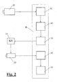
- the spectral measuring head 30 can be moved to any measuring position on the document V located on the platen 12, wherein the control of the movement of the spectral measuring head by a computer R (Fig. 2), which contains the information about the measuring positions to be approached.
- the computer R also controls the triggering of the measuring operations of the spectral measuring head 30 and the transfer of the measured values determined here (in this case spectral measured values) into a memory of the computer.
- the spectral measuring head 30 is designed in a manner known per se as a combined remission / transmission measuring head.
- the support plate 12 is transparent, and in the substructure, a lighting arrangement, not shown here is provided which illuminates the usable, the spectral measuring head 30 can be painted over surface of the support plate 12 as homogeneously as possible.
- the computer-controlled displacement table 10 and the spectral measuring head 30 correspond fully and completely to the state the technique, so that the expert requires no further explanation.
- An example of a known spectral measuring head and a known displacement table are the devices marketed under the names "Spectrolino" and "SpectroScan" by the applicant.
- a suitable for the present invention known spectral measuring head is for example in the US Pat. No. 6,043,893 described. Instead of the spectral measuring head, a likewise conventional tristimulus or similar color measuring head could also be provided.
- the likewise conventional and color-compatible digital camera 20 connected to the computer R detects the original V lying on the support plate 12 and generates a high-resolution digital color representation of the entire or at least the relevant region of the original.
- the illumination device 22 serves to illuminate the original during scanning by the digital camera.
- the lighting arrangement in the substructure is used for this purpose.
- FIG. 1 The interaction of the individual components of the measuring device and the basic principle of the measuring method according to the invention are shown schematically in FIG.
- the original V is pixel-wise photoelectrically scanned by the digital camera 20 and a digital color representation 41 of the original V is formed from the samples obtained and stored in the computer R-controlled by the computer R.
- the bridge 13 and the spectral measuring head 30 are in a rest position in which they are outside the detection range of the digital camera.
- the computer R determines, according to methods of image processing known per se, by means of suitable analysis software 42 and previously stored reference data from templates, the entirety of all measuring positions 43 at which the original is to be measured colorimetrically by means of the spectral measuring head 30. Further details will be explained below.
- the computer R then controls on the basis of these thus determined measuring positions 43 in a conventional manner to the total of 14 designated drive means for the displacement of the bridge 13 and the spectral measuring head 30 and thus moves the spectral measuring head 30 successively to all measuring positions. In every measuring position a measurement is triggered.
- the thereby obtained, generally designated 44 spectral measurement data are read into the computer R and stored there for further processing by a suitable processing program 45, such as one for creating device profiles.
- high-resolution is understood to mean that the size of the scanning points of the imaging unit, in this exemplary embodiment of the digital camera 20, is substantially smaller, in particular by a factor of> 10, than the measuring aperture of the color measuring head 30.
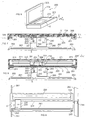
- FIGS. 3-5 schematically show an embodiment of the measuring device according to the invention constructed on the principle of a feed-in scanner.
- the illustrated measuring device comprises a housing 100 and on two opposite sides thereof a collection tray 101 and a discharge tray 102 which lie substantially in one plane.
- a document transport mechanism comprising two motor-driven roller pairs 103 and 104, guides 105 and 106 and two light barriers 107 and 108.
- the document transport mechanism is controlled by a conventional internal controller, not shown here, in combination with an external computer and allows a document V inserted into the input tray 101 in the direction of the arrow X along a substantially planar path defined by the guides 105 and 106 to be transported through the housing in the discharge tray 102 and vice versa.
- the imaging unit or line camera 120 can be constructed, for example, in a manner known per se as a color-capable CIS (contact image sensor). It typically comprises an opto-electrical line sensor 121, an optical imaging unit 122 and an illumination 123 for incident light measurement of opaque templates.
- the imaging unit 120 scans the document transversely to the transporting direction X thereof (in the direction of the arrow Y, FIG. 5) pointwise, wherein the second scanning dimension is detected by the advance of the document.
- the imaging unit is connected in a conventional manner with the internal control and the external computer, which reads in the scanning signals generated by it and forms a digital color representation of the template and stores it.
- the measuring device substantially corresponds to a conventional color-proof feed scanner for opaque templates, so that the expert in this regard requires no further explanation.
- a color or spectral measuring head 130 known per se is additionally provided in the housing 100 and by means of a displacement unit transverse to the transport direction X of the original V in the direction of the arrow Y (FIG Width of the template moved back and forth.
- the conventionally constructed displacement unit consists of a guide shaft 141, a support 142 and a motor-driven drive belt 143 (FIG. 5) and is controlled by the external computer in a manner also known per se.
- the shift unit allows the color or spectral measuring head 130 to be adjusted across the entire width of the document.
- the color or spectral measuring head 130 can be embodied with all technologies commonly used in colorimetry. It typically consists of a lighting unit; which is preferably designed as a 45 ° ring lighting, and a pick-up channel which supplies the light to be measured at 0 ° to a module which performs the spectral selection.
- the wavelength selection is preferably carried out with a diode array spectrometer or with a set of interference filters. Another method for wavelength selection is based on the use of LEDs with different ones Wavelengths as illumination and a spectrally broadband photoelectric receiver. Such a spectrometer is eg in the US Pat. No. 6,043,893 described.
- an additional illumination arrangement 150 is provided below the measuring aperture 131 of the color measuring head 130.
- the illumination arrangement 150 can at the same time also be embodied as transmission illumination for the imaging unit or line scan camera 120 and for this purpose comprises a deflection optics 153 and a further diffuser 154 which extends below the imaging unit along the same.
- a deflection optics 153 and a further diffuser 154 which extends below the imaging unit along the same.
- FIGS. 6-9 schematically show an embodiment of the measuring device according to the invention constructed on the principle of a flatbed scanner. It consists on the one hand of a structure, as is customary in flatbed scanners, and on the other hand of a sliding over the entire template area color measuring head.
- the difference to a feeder scanner consists essentially only in that the template is stationary and for the scanning line is arranged to be movable relative to the original.
- the assembly 200 consists of a base 201 and a hinged lid 202 with a white insert 204, which serves as a background for remission measurements.
- the lower part 201 comprises a housing, which is closed at the top of a glass plate 203, on which the template to be measured V is placed.
- the line sensor extends in the Y direction and is arranged so that it can detect the entire width of the original.
- a spectrally operating color measuring head 230 with a measuring opening 231 is arranged displaceably on a displacement unit parallel to the scanning line 220, that is to say in the direction of the arrow Y.
- the displacement unit is essentially conventional and consists of a guide shaft 241, a support 242 and a motor-driven drive belt 243 (FIG. 8).
- the shift unit allows the color or spectral measuring head 230 to be adjusted across the entire width of the document.
- the imaging unit 220 and the colorimeter head 230 are in turn mounted on a second displacement unit which consists of a carriage 260, a guide shaft 261, a support 262, a roller 264 and a power driven drive belt 263 ( Figure 7).
- This second shifting unit allows the scanning line 220 to be displaced together with the color measuring head 230 in the direction of the arrow X, so that they can scan the entire original V.
- the shifting units, the scanning line and the color measuring head are, as in the preceding embodiment, in turn driven in a manner known per se by a conventional internal control, not shown here, in combination with an external computer.
- an additional illumination arrangement 250 is provided, which preferably - analogous to the exemplary embodiment of FIGS. 3-5 - simultaneously serves for the scanning line 220 and for the color measuring head 230.
- a transparent plate 205 is provided instead of the white insert 204.
- the illumination arrangement 250 comprises a light source 251 (eg a fluorescent tube) extending transversely across the template, a diffuser 252, a deflection optics 253 and a further diffuser 254, and black backgrounds 255 and 256.
- the illumination arrangement 250 is arranged on a further displacement unit which in the FIG is essentially the same as that for the common displacement of scanning line 220 and color measuring head 230 in the X direction and a guide shaft 271 and a motor-driven drive belt 273 consists.
- the additional illumination arrangement 250 is moved in parallel and synchronous with the scanning line 220 or with the color measuring head 230 in the direction of the arrow X during the scanning or colorimetric measurement.
- remission measurements with white or with a black background can be carried out.
- the measuring device essentially corresponds in structure and mode of operation to a conventional color-suitable flatbed scanner for opaque or transparent originals, so that the person skilled in the art needs no further explanation.
- the control of the individual components of this embodiment is analogous to the feed-scanner embodiment by the conventional internal control in combination with an external computer and therefore also requires no particular explanation.
- the measuring method according to the invention is described in more detail below with reference to the example of the measurement of an opaque color test chart (test chart) (remission measurement).
- the test chart to be measured is positioned on the measuring device according to the invention according to one of the described embodiments.
- a color image of the test chart is first recorded in a conventional manner and stored in the computer.
- This color image is taken with the calculator analyzed using image processing methods, whereby the type of test chart and the exact position of the individual color fields (measurement positions) are determined. Algorithms that can accomplish this task are well known today and described in the pertinent literature.
- a possible procedure for the analysis of the test chart is as follows: First the segmentation of the fields of the same color and the determination of their center of gravity are used to calculate a first approximation of the coordinates of the color fields. When segmenting the fields, the fact can be exploited that the color fields of a test card usually have the same size.
- the information thus obtained about the structure of the color test card (position and color of the color patches) is compared with the reference data of the color test cards (stored in the computer) and thus the type of color test chart is determined.
- the desired position of the color fields from the structure of the reference card is known, the previously calculated position of each color field can be checked and any artifacts in the image resulting Segment réellesirri and thus positioning errors can be eliminated.
- the colorimetric values and possibly the spectrum are determined with the color measuring head 30 or 130 or 230 at the measuring positions determined in this way and preferably stored in the computer in a format defined in a text file. From these colorimetric data of the original, it is then possible to use, for example, software known per se. an ICC profile can be calculated.
- the procedure for measuring a transmission test chart is analogous to the remission measurement described above.
- the inhomogeneity of the transmitted light illumination is measured with the scanner or the digital camera and the spectral measured values determined by the color measuring head are thereby compensated.
- the light distribution of the transmitted light illumination is measured and stored with the imaging unit. Thereafter, the test chart is placed in the scanner or on the measuring table and a picture taken of the same. This image is analyzed with a computer using image processing methods, determining the type of test chart and the exact location of each color field (see above). The colorimetric values and / or the spectrum of the color fields are subsequently determined with the color measuring head at the locations thus found.
- the artifacts in the spectral measurements which are caused by the locally non-constant (inhomogeneous) transmission illumination, can then be compensated with the previously recorded data of the image of the light distribution of the transmission illumination.
- an ICC profile of a foil printer can then be calculated from the colorimetric data determined in this way.
- Another important aspect of the invention is the possibility of measuring in the image to calculate rule recommendations for controlling output devices such as printing machines.
- spectral scanners are used today, which capture the complete spectrum of each pixel. While this is an elegant, but very expensive method due to the complex hardware of a spectral scanner.
- a suitable for this purpose spectral scanner the company Heidelberg printing machines is eg in EP-A 0 847 187 described.
- the prepress data of the original to be printed are transferred in digital form (eg in PDF or CIP3 format).
- digital form eg in PDF or CIP3 format.
- those points in the image are automatically determined in a manner known per se, which are best suited for the control because of their color composition (layer structure) and the homogeneity of the image hierarchy.
- the user can be given the opportunity to modify these points (add, delete or move points).
- a first sheet is now output and placed on the measuring device according to the invention.
- an image of the printed sheet is taken with a scanner or digital camera. This image is correlated with the prepress data, allowing the positions of the spectrally measured points on the template to be determined very accurately without user interaction.
- the colorimetric information is now determined with the spectral measuring head, and from this, using suitable algorithms, the rule recommendations for the output device are determined in a manner known per se. With the settings of the output device that are new according to these rule recommendations, another sheet is output and measured as described above, and the control parameters are adjusted, if necessary, until the required quality is achieved. Thereafter, only at certain intervals an arc is measured and, if appropriate, the control parameters adjusted to guarantee a consistent quality of the output.
- the user does not have to specify the position of the color patches (measurement positions) as well as the type of the test chart, since this information is determined by means of image processing methods from the image data of the template. This procedure increases user-friendliness and eliminates a potential source of error.
- the high local resolution of the scanner or the digital camera which can be achieved in comparison to a scanning color measuring head, makes the position of the color fields very accurate be determined.
- the smallest colorimetrically measurable color field size can only be selected to be insignificantly larger than the measuring aperture of the color measuring head, without erroneous measurements resulting from incorrect positioning and thus co-evaluation of the light from adjacent fields.
- Small boxes allow a large number of color patches for a given document size, which benefits the quality of the ICC profiles.
- the time required to acquire the colorimetric measured values is significantly shortened.
- test chart is not only colormetrically but also digitally as a high-resolution image after the measurement, artefacts resulting from contamination or scratches can be detected in the colorimetric measured values and ignored, corrected or measured again.
- the color measurement head can be used to significantly increase the accuracy of the colorimetric values by multiple measurements at various points in the field and subsequent averaging. From the analysis of the image data of the template, the homogeneity of the individual color fields can be determined. If this is low, the quality can be kept within acceptable limits automatically by multiple measurements.
- the measurement time can be significantly shortened.
Applications Claiming Priority (1)
| Application Number | Priority Date | Filing Date | Title |
|---|---|---|---|
| EP00117208A EP1180898B1 (fr) | 2000-08-11 | 2000-08-11 | Méthode et dispositif pour la mesure colorimétrique d'un document bidimensionnel |
Related Parent Applications (1)
| Application Number | Title | Priority Date | Filing Date |
|---|---|---|---|
| EP00117208A Division EP1180898B1 (fr) | 2000-08-11 | 2000-08-11 | Méthode et dispositif pour la mesure colorimétrique d'un document bidimensionnel |
Publications (2)
| Publication Number | Publication Date |
|---|---|
| EP1703717A2 true EP1703717A2 (fr) | 2006-09-20 |
| EP1703717A3 EP1703717A3 (fr) | 2008-07-30 |
Family
ID=8169495
Family Applications (2)
| Application Number | Title | Priority Date | Filing Date |
|---|---|---|---|
| EP06011729A Withdrawn EP1703717A3 (fr) | 2000-08-11 | 2000-08-11 | Méthode et dispositif pour la mesure colorimétrique d'un document bidimensionnel |
| EP00117208A Expired - Lifetime EP1180898B1 (fr) | 2000-08-11 | 2000-08-11 | Méthode et dispositif pour la mesure colorimétrique d'un document bidimensionnel |
Family Applications After (1)
| Application Number | Title | Priority Date | Filing Date |
|---|---|---|---|
| EP00117208A Expired - Lifetime EP1180898B1 (fr) | 2000-08-11 | 2000-08-11 | Méthode et dispositif pour la mesure colorimétrique d'un document bidimensionnel |
Country Status (5)
| Country | Link |
|---|---|
| US (1) | US6765674B2 (fr) |
| EP (2) | EP1703717A3 (fr) |
| JP (1) | JP2002131134A (fr) |
| CA (1) | CA2354881A1 (fr) |
| DE (1) | DE50013566D1 (fr) |
Families Citing this family (37)
| Publication number | Priority date | Publication date | Assignee | Title |
|---|---|---|---|---|
| EP1185081A1 (fr) * | 2000-08-30 | 2002-03-06 | Gretag-Macbeth AG | Procédé et dispositif pour produire une image couleur numerique |
| EP1743148B1 (fr) * | 2004-05-05 | 2010-03-03 | X-Rite, Inc. | Spectrophotometre a poursuite automatique |
| JP4511322B2 (ja) * | 2004-11-25 | 2010-07-28 | 株式会社エルモ社 | 撮像装置 |
| US20060152542A1 (en) * | 2005-01-11 | 2006-07-13 | Dispoto Gary J | System and method for performing measurements on a target medium |
| EP1872102A4 (fr) * | 2005-04-05 | 2013-05-01 | X Rite Inc | Systemes et procedes de surveillance de la sortie d'un traitement avec un spectrophotometre hautement accelere |
| WO2006110865A2 (fr) * | 2005-04-12 | 2006-10-19 | X-Rite, Incorporated | Systemes et procedes pour valider un element de securite d'un objet |
| EP1922532B1 (fr) * | 2005-08-15 | 2012-12-12 | X-Rite, Incorporated | Instrument optique ameliore |
| US7557925B2 (en) * | 2005-08-15 | 2009-07-07 | X-Rite, Inc. | Optical instrument and parts thereof for optimally defining light pathways |
| DE102007030571B4 (de) * | 2006-08-03 | 2020-04-09 | Heidelberger Druckmaschinen Ag | Farbmessvorrichtung mit zwei unterschiedlich arbeitenden Messeinrichtungen |
| US8553090B2 (en) * | 2006-09-08 | 2013-10-08 | Kingston Technology Corporation | Portable image capture and camera device |
| DE102006048539A1 (de) | 2006-10-13 | 2008-04-17 | Heidelberger Druckmaschinen Ag | Farbmesskopfpositionierungsvorrichtung |
| CN100592202C (zh) * | 2007-05-15 | 2010-02-24 | 鸿富锦精密工业(深圳)有限公司 | 相机模组的影像测试系统及方法 |
| DE102007041673A1 (de) * | 2007-06-29 | 2009-01-08 | Koenig & Bauer Aktiengesellschaft | Verfahren und Messeinrichtung zur Gewinnung von Druckbild- oder Druckplatteninformationen |
| EP2199765B1 (fr) * | 2008-12-18 | 2013-10-16 | X-Rite Europe GmbH | Procédé et appareil de mesure de couleur manuelle destinés à la mesure d'une échelle de mesure de couleur |
| JP5424957B2 (ja) * | 2009-04-30 | 2014-02-26 | キヤノン株式会社 | 分光測色装置およびそれを用いた画像形成装置 |
| DE102009027262A1 (de) * | 2009-06-29 | 2011-03-03 | Manroland Ag | Abmusterungstisch einer Druckmaschine |
| JP2011060270A (ja) * | 2009-08-10 | 2011-03-24 | Canon Inc | 印刷システムおよび方法 |
| CN102200427A (zh) * | 2010-03-22 | 2011-09-28 | 鸿富锦精密工业(深圳)有限公司 | 影像测量机 |
| US8736840B1 (en) * | 2010-05-23 | 2014-05-27 | Arkady Ten | Method for finding an aim position of a measuring device |
| DE202011050535U1 (de) * | 2011-06-22 | 2012-09-24 | Eltromat Gmbh | Bahnbeobachtungssystem für Rotationsdruckmaschinen |
| US9264583B2 (en) | 2012-04-24 | 2016-02-16 | Hewlett-Packard Development Company, L.P. | Printing system and method for backlit substrate calibration |
| JP5701837B2 (ja) * | 2012-10-12 | 2015-04-15 | 横河電機株式会社 | 変位センサ、変位測定方法 |
| JP6323049B2 (ja) * | 2014-02-19 | 2018-05-16 | セイコーエプソン株式会社 | 測色方法、測色装置及び印刷装置 |
| WO2015166798A1 (fr) * | 2014-04-28 | 2015-11-05 | コニカミノルタ株式会社 | Dispositif et procédé de mesure des couleurs |
| EP3141879B1 (fr) * | 2014-04-28 | 2019-07-03 | Konica Minolta, Inc. | Dispositif de mesure de couleur et procédé de mesure de couleur |
| WO2015170603A1 (fr) * | 2014-05-07 | 2015-11-12 | コニカミノルタ株式会社 | Dispositif de mesure de couleur et procédé de mesure de couleur |
| CN106461464B (zh) * | 2014-05-13 | 2018-04-20 | 柯尼卡美能达株式会社 | 测色装置以及测色方法 |
| US10254168B2 (en) | 2014-11-14 | 2019-04-09 | Konica Minolta, Inc. | Colorimeter device and colorimetery method |
| JP6610556B2 (ja) | 2014-11-14 | 2019-11-27 | コニカミノルタ株式会社 | 測色装置および測色方法 |
| WO2016152334A1 (fr) * | 2015-03-26 | 2016-09-29 | コニカミノルタ株式会社 | Dispositif et procédé de colorimétrie |
| US10578491B2 (en) | 2015-04-01 | 2020-03-03 | Konica Minolta, Inc. | Colorimetry device and colorimetry method |
| US10502627B2 (en) * | 2015-04-06 | 2019-12-10 | Konica Minolta, Inc. | Color measuring device and color measuring method |
| JP6733191B2 (ja) * | 2016-01-29 | 2020-07-29 | セイコーエプソン株式会社 | 測定装置、及び測定方法 |
| US10455156B2 (en) | 2016-02-29 | 2019-10-22 | Hewlett-Packard Development Company, L.P. | Using unidirectional and omnidirectional antennas to determine whether object image is in camera viewfinder |
| JP7187983B2 (ja) | 2018-10-30 | 2022-12-13 | コニカミノルタ株式会社 | 分光測色装置 |
| JP7229782B2 (ja) | 2019-01-09 | 2023-02-28 | キヤノン株式会社 | 測定装置及び画像形成システム |
| CN114257736A (zh) * | 2021-11-12 | 2022-03-29 | 北京京仪仪器仪表研究总院有限公司 | 一种工件自适应拍摄方法 |
Citations (2)
| Publication number | Priority date | Publication date | Assignee | Title |
|---|---|---|---|---|
| EP0064024A1 (fr) * | 1981-04-03 | 1982-11-03 | GRETAG Aktiengesellschaft | Procédé et dispositif pour l'analyse colorimétrique d'une bande de mesure d'impression colorée |
| US6005968A (en) * | 1997-08-29 | 1999-12-21 | X-Rite, Incorporated | Scanner calibration and correction techniques using scaled lightness values |
Family Cites Families (21)
| Publication number | Priority date | Publication date | Assignee | Title |
|---|---|---|---|---|
| EP0281659B1 (fr) * | 1987-03-13 | 1989-09-27 | Dr.-Ing. Rudolf Hell GmbH | Procédé et appareil d'ajustage du niveau de blanc |
| US4933778A (en) * | 1988-09-19 | 1990-06-12 | Eastman Kodak Company | Calibration of platen registration edges in copiers |
| CA2035658A1 (fr) * | 1990-02-05 | 1991-08-06 | Zeev Smilansky | Methode et appareil d'etalonnage chromatique |
| US5191406A (en) * | 1990-04-20 | 1993-03-02 | Nikon Corporation | Method and apparatus for rapid scanning of color images |
| US5047861A (en) * | 1990-07-31 | 1991-09-10 | Eastman Kodak Company | Method and apparatus for pixel non-uniformity correction |
| IL98622A (en) * | 1991-06-25 | 1996-10-31 | Scitex Corp Ltd | Method and device for using neural networks in figure work |
| US5149960B1 (en) * | 1991-07-03 | 1994-08-30 | Donnelly R R & Sons | Method of converting scanner signals into colorimetric signals |
| US5200817A (en) * | 1991-08-29 | 1993-04-06 | Xerox Corporation | Conversion of an RGB color scanner into a colorimetric scanner |
| DE4305693C2 (de) * | 1992-04-06 | 1996-12-19 | Hell Ag Linotype | Verfahren zur Farbkalibrierung |
| JP3086535B2 (ja) * | 1992-06-05 | 2000-09-11 | 富士写真フイルム株式会社 | 画像処理方法および装置 |
| US5956044A (en) * | 1993-05-07 | 1999-09-21 | Eastman Kodak Company | Imaging device to media compatibility and color appearance matching with flare, luminance, and white point comparison |
| US5537516A (en) * | 1994-03-15 | 1996-07-16 | Electronics For Imaging, Inc. | Method for calibrating a color printer using a scanner for color measurements |
| US5642202A (en) * | 1994-12-01 | 1997-06-24 | Xerox Corporation | Scan image target locator system for calibrating a printing system |
| US5754448A (en) * | 1995-07-12 | 1998-05-19 | Minnesota Mining And Manufacturing Company | System and method for color characterization and transformation |
| JPH09178564A (ja) * | 1995-12-21 | 1997-07-11 | Shimadzu Corp | 分光測定装置 |
| US6075888A (en) * | 1996-01-11 | 2000-06-13 | Eastman Kodak Company | System for creating a device specific color profile |
| DE19649797A1 (de) * | 1996-12-02 | 1998-06-04 | Hell Ag Linotype | Verfahren zum Abgleich eines Abtastgerätes |
| DE19650223A1 (de) * | 1996-12-04 | 1998-06-10 | Heidelberger Druckmasch Ag | Abtastvorrichtung zur bildelementweisen fotoelektrischen Ausmessung eines Messobjekts |
| US6088095A (en) * | 1998-11-12 | 2000-07-11 | Xerox Corporation | Model-based spectral calibration of color scanners |
| US6459825B1 (en) * | 1999-02-18 | 2002-10-01 | Phillips M. Lippincott | Method and apparatus for a self learning automatic control of photo capture and scanning |
| US20020122589A1 (en) * | 1999-11-29 | 2002-09-05 | Donald M. Reiman | Constructing profiles to compensate for non-linearities in image capture |
-
2000
- 2000-08-11 EP EP06011729A patent/EP1703717A3/fr not_active Withdrawn
- 2000-08-11 EP EP00117208A patent/EP1180898B1/fr not_active Expired - Lifetime
- 2000-08-11 DE DE50013566T patent/DE50013566D1/de not_active Expired - Lifetime
-
2001
- 2001-08-09 CA CA002354881A patent/CA2354881A1/fr not_active Abandoned
- 2001-08-10 US US09/925,748 patent/US6765674B2/en not_active Expired - Lifetime
- 2001-08-13 JP JP2001245659A patent/JP2002131134A/ja active Pending
Patent Citations (2)
| Publication number | Priority date | Publication date | Assignee | Title |
|---|---|---|---|---|
| EP0064024A1 (fr) * | 1981-04-03 | 1982-11-03 | GRETAG Aktiengesellschaft | Procédé et dispositif pour l'analyse colorimétrique d'une bande de mesure d'impression colorée |
| US6005968A (en) * | 1997-08-29 | 1999-12-21 | X-Rite, Incorporated | Scanner calibration and correction techniques using scaled lightness values |
Also Published As
| Publication number | Publication date |
|---|---|
| US6765674B2 (en) | 2004-07-20 |
| US20020054292A1 (en) | 2002-05-09 |
| EP1703717A3 (fr) | 2008-07-30 |
| CA2354881A1 (fr) | 2002-02-11 |
| EP1180898B1 (fr) | 2006-10-04 |
| JP2002131134A (ja) | 2002-05-09 |
| DE50013566D1 (de) | 2006-11-16 |
| EP1180898A1 (fr) | 2002-02-20 |
Similar Documents
| Publication | Publication Date | Title |
|---|---|---|
| EP1180898B1 (fr) | Méthode et dispositif pour la mesure colorimétrique d'un document bidimensionnel | |
| EP1805979B1 (fr) | Procede de correction de valeurs mesurees d'images | |
| EP0884178B1 (fr) | Procédé pour reguler l'encrage dans une machine d'impression | |
| EP1936337B1 (fr) | Tête manométrique et dispositif de balayage et dispositif de balayage équipé de celle-ci | |
| DE19722073C2 (de) | Verfahren und Zeilendrucker für die digitale Ausgabe und farbmetrische Messung von farbigen Bildern | |
| EP0713447B1 (fr) | Dispositif de verification d'image d'un produit imprime | |
| DE60216664T2 (de) | Spektrophotometer zur Farbsteuerung eines Farbdruckgeräts, unempfindlich gegen Winkel-, Azimuth- und Abstandsänderung | |
| EP1744884B1 (fr) | Procede pour determiner des valeurs de densite et/ou d'encrage et dispositif d'impression pour la mise en oeuvre dudit procede | |
| EP1501280B1 (fr) | Imprimante numérique | |
| DE102007030571B4 (de) | Farbmessvorrichtung mit zwei unterschiedlich arbeitenden Messeinrichtungen | |
| DE19802920B4 (de) | Verfahren und Vorrichtung zur Farbregelung in Druckmaschinen | |
| DE3714895A1 (de) | Bildinformationsabtastvorrichtung mit einstellzustand-anzeigefunktion | |
| EP1092972A1 (fr) | Dispositif pour mesures automatiques de champs de mesure | |
| DE69533802T2 (de) | Abtastkolorimeter | |
| DE19939154A1 (de) | Verfahren und Meßvorrichtung zur Druckkontrolle und Bildanalyse | |
| DE102007041673A1 (de) | Verfahren und Messeinrichtung zur Gewinnung von Druckbild- oder Druckplatteninformationen | |
| DE60104458T2 (de) | Mehrauflösungabtaster mit verbesserten Lampenhelligkeitüberwachungsfähigkeiten | |
| EP2199765B1 (fr) | Procédé et appareil de mesure de couleur manuelle destinés à la mesure d'une échelle de mesure de couleur | |
| DE60003018T2 (de) | Verfahren zum kalibrieren der kamera eines farbüberwachungssystems | |
| EP2034286B1 (fr) | Méthode de contrôle d'un processus d'impression utilisant un système de mesure spectral comprenant un modulateur spatial de lumière | |
| DE4131303A1 (de) | Verfahren und vorrichtung zur optoelektronischen bildabtastung und druckbilderzeugung fuer den druckprozess einer offset-druckmaschine | |
| DE102012108207A1 (de) | Farbmesseinrichtung für Druckmaschinen | |
| DE19939162A1 (de) | Verfahren für die wahlweise farbmetrische oder densitometrische Analyse von Bildpunkten mehrfarbiger, in ein Meßfeld gemeinsam angeordneter Rasterstrukturen auf Druckerzeugnissen und portables Densitometer und Farbmeßgerät |
Legal Events
| Date | Code | Title | Description |
|---|---|---|---|
| PUAI | Public reference made under article 153(3) epc to a published international application that has entered the european phase |
Free format text: ORIGINAL CODE: 0009012 |
|
| 17P | Request for examination filed |
Effective date: 20060607 |
|
| AC | Divisional application: reference to earlier application |
Ref document number: 1180898 Country of ref document: EP Kind code of ref document: P |
|
| AK | Designated contracting states |
Kind code of ref document: A2 Designated state(s): CH DE FR GB IT LI |
|
| PUAL | Search report despatched |
Free format text: ORIGINAL CODE: 0009013 |
|
| AK | Designated contracting states |
Kind code of ref document: A3 Designated state(s): CH DE FR GB IT LI |
|
| RIC1 | Information provided on ipc code assigned before grant |
Ipc: H04N 1/60 20060101AFI20060811BHEP Ipc: G01N 21/59 20060101ALI20080624BHEP |
|
| 17Q | First examination report despatched |
Effective date: 20090306 |
|
| AKX | Designation fees paid |
Designated state(s): CH DE FR GB IT LI |
|
| STAA | Information on the status of an ep patent application or granted ep patent |
Free format text: STATUS: THE APPLICATION IS DEEMED TO BE WITHDRAWN |
|
| 18D | Application deemed to be withdrawn |
Effective date: 20090917 |