EP1701775B1 - Verfahren und prozess zur steuerung der temperatur-, druck- und dichteprofile in prozessen mit dichten fluiden und vorrichtung dafür - Google Patents
Verfahren und prozess zur steuerung der temperatur-, druck- und dichteprofile in prozessen mit dichten fluiden und vorrichtung dafür Download PDFInfo
- Publication number
- EP1701775B1 EP1701775B1 EP20040797466 EP04797466A EP1701775B1 EP 1701775 B1 EP1701775 B1 EP 1701775B1 EP 20040797466 EP20040797466 EP 20040797466 EP 04797466 A EP04797466 A EP 04797466A EP 1701775 B1 EP1701775 B1 EP 1701775B1
- Authority
- EP
- European Patent Office
- Prior art keywords
- vessel
- fluid
- pressure
- extraction
- temperature
- Prior art date
- Legal status (The legal status is an assumption and is not a legal conclusion. Google has not performed a legal analysis and makes no representation as to the accuracy of the status listed.)
- Expired - Lifetime
Links
Images



Classifications
-
- B—PERFORMING OPERATIONS; TRANSPORTING
- B01—PHYSICAL OR CHEMICAL PROCESSES OR APPARATUS IN GENERAL
- B01D—SEPARATION
- B01D11/00—Solvent extraction
-
- B—PERFORMING OPERATIONS; TRANSPORTING
- B27—WORKING OR PRESERVING WOOD OR SIMILAR MATERIAL; NAILING OR STAPLING MACHINES IN GENERAL
- B27K—PROCESSES, APPARATUS OR SELECTION OF SUBSTANCES FOR IMPREGNATING, STAINING, DYEING, BLEACHING OF WOOD OR SIMILAR MATERIALS, OR TREATING OF WOOD OR SIMILAR MATERIALS WITH PERMEANT LIQUIDS, NOT OTHERWISE PROVIDED FOR; CHEMICAL OR PHYSICAL TREATMENT OF CORK, CANE, REED, STRAW OR SIMILAR MATERIALS
- B27K3/00—Impregnating wood, e.g. impregnation pretreatment, for example puncturing; Wood impregnation aids not directly involved in the impregnation process
- B27K3/02—Processes; Apparatus
- B27K3/08—Impregnating by pressure, e.g. vacuum impregnation
- B27K3/086—Impregnating by pressure, e.g. vacuum impregnation using supercritical or high pressure fluids
-
- B—PERFORMING OPERATIONS; TRANSPORTING
- B01—PHYSICAL OR CHEMICAL PROCESSES OR APPARATUS IN GENERAL
- B01D—SEPARATION
- B01D11/00—Solvent extraction
- B01D11/02—Solvent extraction of solids
-
- B—PERFORMING OPERATIONS; TRANSPORTING
- B01—PHYSICAL OR CHEMICAL PROCESSES OR APPARATUS IN GENERAL
- B01D—SEPARATION
- B01D11/00—Solvent extraction
- B01D11/02—Solvent extraction of solids
- B01D11/0203—Solvent extraction of solids with a supercritical fluid
-
- B—PERFORMING OPERATIONS; TRANSPORTING
- B01—PHYSICAL OR CHEMICAL PROCESSES OR APPARATUS IN GENERAL
- B01D—SEPARATION
- B01D11/00—Solvent extraction
- B01D11/02—Solvent extraction of solids
- B01D11/0261—Solvent extraction of solids comprising vibrating mechanisms, e.g. mechanical, acoustical
- B01D11/0265—Applying ultrasound
-
- B—PERFORMING OPERATIONS; TRANSPORTING
- B01—PHYSICAL OR CHEMICAL PROCESSES OR APPARATUS IN GENERAL
- B01D—SEPARATION
- B01D11/00—Solvent extraction
- B01D11/02—Solvent extraction of solids
- B01D11/028—Flow sheets
-
- B—PERFORMING OPERATIONS; TRANSPORTING
- B01—PHYSICAL OR CHEMICAL PROCESSES OR APPARATUS IN GENERAL
- B01D—SEPARATION
- B01D11/00—Solvent extraction
- B01D11/02—Solvent extraction of solids
- B01D11/0292—Treatment of the solvent
- B01D11/0296—Condensation of solvent vapours
-
- B—PERFORMING OPERATIONS; TRANSPORTING
- B01—PHYSICAL OR CHEMICAL PROCESSES OR APPARATUS IN GENERAL
- B01D—SEPARATION
- B01D11/00—Solvent extraction
- B01D11/04—Solvent extraction of solutions which are liquid
- B01D11/0403—Solvent extraction of solutions which are liquid with a supercritical fluid
- B01D11/0411—Solvent extraction of solutions which are liquid with a supercritical fluid the supercritical fluid acting as solvent for the solvent and as anti-solvent for the solute, e.g. formation of particles from solutions
-
- B—PERFORMING OPERATIONS; TRANSPORTING
- B01—PHYSICAL OR CHEMICAL PROCESSES OR APPARATUS IN GENERAL
- B01D—SEPARATION
- B01D15/00—Separating processes involving the treatment of liquids with solid sorbents; Apparatus therefor
- B01D15/08—Selective adsorption, e.g. chromatography
-
- B—PERFORMING OPERATIONS; TRANSPORTING
- B01—PHYSICAL OR CHEMICAL PROCESSES OR APPARATUS IN GENERAL
- B01J—CHEMICAL OR PHYSICAL PROCESSES, e.g. CATALYSIS OR COLLOID CHEMISTRY; THEIR RELEVANT APPARATUS
- B01J19/00—Chemical, physical or physico-chemical processes in general; Their relevant apparatus
- B01J19/0006—Controlling or regulating processes
-
- B—PERFORMING OPERATIONS; TRANSPORTING
- B01—PHYSICAL OR CHEMICAL PROCESSES OR APPARATUS IN GENERAL
- B01J—CHEMICAL OR PHYSICAL PROCESSES, e.g. CATALYSIS OR COLLOID CHEMISTRY; THEIR RELEVANT APPARATUS
- B01J20/00—Solid sorbent compositions or filter aid compositions; Sorbents for chromatography; Processes for preparing, regenerating or reactivating thereof
- B01J20/281—Sorbents specially adapted for preparative, analytical or investigative chromatography
- B01J20/286—Phases chemically bonded to a substrate, e.g. to silica or to polymers
-
- B—PERFORMING OPERATIONS; TRANSPORTING
- B01—PHYSICAL OR CHEMICAL PROCESSES OR APPARATUS IN GENERAL
- B01J—CHEMICAL OR PHYSICAL PROCESSES, e.g. CATALYSIS OR COLLOID CHEMISTRY; THEIR RELEVANT APPARATUS
- B01J20/00—Solid sorbent compositions or filter aid compositions; Sorbents for chromatography; Processes for preparing, regenerating or reactivating thereof
- B01J20/30—Processes for preparing, regenerating, or reactivating
- B01J20/32—Impregnating or coating ; Solid sorbent compositions obtained from processes involving impregnating or coating
- B01J20/3202—Impregnating or coating ; Solid sorbent compositions obtained from processes involving impregnating or coating characterised by the carrier, support or substrate used for impregnation or coating
- B01J20/3204—Inorganic carriers, supports or substrates
-
- B—PERFORMING OPERATIONS; TRANSPORTING
- B01—PHYSICAL OR CHEMICAL PROCESSES OR APPARATUS IN GENERAL
- B01J—CHEMICAL OR PHYSICAL PROCESSES, e.g. CATALYSIS OR COLLOID CHEMISTRY; THEIR RELEVANT APPARATUS
- B01J20/00—Solid sorbent compositions or filter aid compositions; Sorbents for chromatography; Processes for preparing, regenerating or reactivating thereof
- B01J20/30—Processes for preparing, regenerating, or reactivating
- B01J20/32—Impregnating or coating ; Solid sorbent compositions obtained from processes involving impregnating or coating
- B01J20/3202—Impregnating or coating ; Solid sorbent compositions obtained from processes involving impregnating or coating characterised by the carrier, support or substrate used for impregnation or coating
- B01J20/3206—Organic carriers, supports or substrates
- B01J20/3208—Polymeric carriers, supports or substrates
-
- B—PERFORMING OPERATIONS; TRANSPORTING
- B01—PHYSICAL OR CHEMICAL PROCESSES OR APPARATUS IN GENERAL
- B01J—CHEMICAL OR PHYSICAL PROCESSES, e.g. CATALYSIS OR COLLOID CHEMISTRY; THEIR RELEVANT APPARATUS
- B01J20/00—Solid sorbent compositions or filter aid compositions; Sorbents for chromatography; Processes for preparing, regenerating or reactivating thereof
- B01J20/30—Processes for preparing, regenerating, or reactivating
- B01J20/32—Impregnating or coating ; Solid sorbent compositions obtained from processes involving impregnating or coating
- B01J20/3202—Impregnating or coating ; Solid sorbent compositions obtained from processes involving impregnating or coating characterised by the carrier, support or substrate used for impregnation or coating
- B01J20/3206—Organic carriers, supports or substrates
- B01J20/3208—Polymeric carriers, supports or substrates
- B01J20/3212—Polymeric carriers, supports or substrates consisting of a polymer obtained by reactions otherwise than involving only carbon to carbon unsaturated bonds
-
- B—PERFORMING OPERATIONS; TRANSPORTING
- B01—PHYSICAL OR CHEMICAL PROCESSES OR APPARATUS IN GENERAL
- B01J—CHEMICAL OR PHYSICAL PROCESSES, e.g. CATALYSIS OR COLLOID CHEMISTRY; THEIR RELEVANT APPARATUS
- B01J20/00—Solid sorbent compositions or filter aid compositions; Sorbents for chromatography; Processes for preparing, regenerating or reactivating thereof
- B01J20/30—Processes for preparing, regenerating, or reactivating
- B01J20/32—Impregnating or coating ; Solid sorbent compositions obtained from processes involving impregnating or coating
- B01J20/3231—Impregnating or coating ; Solid sorbent compositions obtained from processes involving impregnating or coating characterised by the coating or impregnating layer
- B01J20/3242—Layers with a functional group, e.g. an affinity material, a ligand, a reactant or a complexing group
- B01J20/3244—Non-macromolecular compounds
- B01J20/3246—Non-macromolecular compounds having a well defined chemical structure
- B01J20/3248—Non-macromolecular compounds having a well defined chemical structure the functional group or the linking, spacer or anchoring group as a whole comprising at least one type of heteroatom selected from a nitrogen, oxygen or sulfur, these atoms not being part of the carrier as such
- B01J20/3251—Non-macromolecular compounds having a well defined chemical structure the functional group or the linking, spacer or anchoring group as a whole comprising at least one type of heteroatom selected from a nitrogen, oxygen or sulfur, these atoms not being part of the carrier as such comprising at least two different types of heteroatoms selected from nitrogen, oxygen or sulphur
-
- B—PERFORMING OPERATIONS; TRANSPORTING
- B01—PHYSICAL OR CHEMICAL PROCESSES OR APPARATUS IN GENERAL
- B01J—CHEMICAL OR PHYSICAL PROCESSES, e.g. CATALYSIS OR COLLOID CHEMISTRY; THEIR RELEVANT APPARATUS
- B01J20/00—Solid sorbent compositions or filter aid compositions; Sorbents for chromatography; Processes for preparing, regenerating or reactivating thereof
- B01J20/30—Processes for preparing, regenerating, or reactivating
- B01J20/32—Impregnating or coating ; Solid sorbent compositions obtained from processes involving impregnating or coating
- B01J20/3231—Impregnating or coating ; Solid sorbent compositions obtained from processes involving impregnating or coating characterised by the coating or impregnating layer
- B01J20/3242—Layers with a functional group, e.g. an affinity material, a ligand, a reactant or a complexing group
- B01J20/3244—Non-macromolecular compounds
- B01J20/3246—Non-macromolecular compounds having a well defined chemical structure
- B01J20/3248—Non-macromolecular compounds having a well defined chemical structure the functional group or the linking, spacer or anchoring group as a whole comprising at least one type of heteroatom selected from a nitrogen, oxygen or sulfur, these atoms not being part of the carrier as such
- B01J20/3253—Non-macromolecular compounds having a well defined chemical structure the functional group or the linking, spacer or anchoring group as a whole comprising at least one type of heteroatom selected from a nitrogen, oxygen or sulfur, these atoms not being part of the carrier as such comprising a cyclic structure not containing any of the heteroatoms nitrogen, oxygen or sulfur, e.g. aromatic structures
-
- B—PERFORMING OPERATIONS; TRANSPORTING
- B01—PHYSICAL OR CHEMICAL PROCESSES OR APPARATUS IN GENERAL
- B01J—CHEMICAL OR PHYSICAL PROCESSES, e.g. CATALYSIS OR COLLOID CHEMISTRY; THEIR RELEVANT APPARATUS
- B01J20/00—Solid sorbent compositions or filter aid compositions; Sorbents for chromatography; Processes for preparing, regenerating or reactivating thereof
- B01J20/30—Processes for preparing, regenerating, or reactivating
- B01J20/32—Impregnating or coating ; Solid sorbent compositions obtained from processes involving impregnating or coating
- B01J20/3231—Impregnating or coating ; Solid sorbent compositions obtained from processes involving impregnating or coating characterised by the coating or impregnating layer
- B01J20/3242—Layers with a functional group, e.g. an affinity material, a ligand, a reactant or a complexing group
- B01J20/3244—Non-macromolecular compounds
- B01J20/3246—Non-macromolecular compounds having a well defined chemical structure
- B01J20/3248—Non-macromolecular compounds having a well defined chemical structure the functional group or the linking, spacer or anchoring group as a whole comprising at least one type of heteroatom selected from a nitrogen, oxygen or sulfur, these atoms not being part of the carrier as such
- B01J20/3255—Non-macromolecular compounds having a well defined chemical structure the functional group or the linking, spacer or anchoring group as a whole comprising at least one type of heteroatom selected from a nitrogen, oxygen or sulfur, these atoms not being part of the carrier as such comprising a cyclic structure containing at least one of the heteroatoms nitrogen, oxygen or sulfur, e.g. heterocyclic or heteroaromatic structures
-
- B—PERFORMING OPERATIONS; TRANSPORTING
- B01—PHYSICAL OR CHEMICAL PROCESSES OR APPARATUS IN GENERAL
- B01J—CHEMICAL OR PHYSICAL PROCESSES, e.g. CATALYSIS OR COLLOID CHEMISTRY; THEIR RELEVANT APPARATUS
- B01J20/00—Solid sorbent compositions or filter aid compositions; Sorbents for chromatography; Processes for preparing, regenerating or reactivating thereof
- B01J20/30—Processes for preparing, regenerating, or reactivating
- B01J20/32—Impregnating or coating ; Solid sorbent compositions obtained from processes involving impregnating or coating
- B01J20/3231—Impregnating or coating ; Solid sorbent compositions obtained from processes involving impregnating or coating characterised by the coating or impregnating layer
- B01J20/3242—Layers with a functional group, e.g. an affinity material, a ligand, a reactant or a complexing group
- B01J20/3244—Non-macromolecular compounds
- B01J20/3246—Non-macromolecular compounds having a well defined chemical structure
- B01J20/3257—Non-macromolecular compounds having a well defined chemical structure the functional group or the linking, spacer or anchoring group as a whole comprising at least one of the heteroatoms nitrogen, oxygen or sulfur together with at least one silicon atom, these atoms not being part of the carrier as such
-
- B—PERFORMING OPERATIONS; TRANSPORTING
- B01—PHYSICAL OR CHEMICAL PROCESSES OR APPARATUS IN GENERAL
- B01J—CHEMICAL OR PHYSICAL PROCESSES, e.g. CATALYSIS OR COLLOID CHEMISTRY; THEIR RELEVANT APPARATUS
- B01J3/00—Processes of utilising sub-atmospheric or super-atmospheric pressure to effect chemical or physical change of matter; Apparatus therefor
-
- B—PERFORMING OPERATIONS; TRANSPORTING
- B01—PHYSICAL OR CHEMICAL PROCESSES OR APPARATUS IN GENERAL
- B01J—CHEMICAL OR PHYSICAL PROCESSES, e.g. CATALYSIS OR COLLOID CHEMISTRY; THEIR RELEVANT APPARATUS
- B01J3/00—Processes of utilising sub-atmospheric or super-atmospheric pressure to effect chemical or physical change of matter; Apparatus therefor
- B01J3/008—Processes carried out under supercritical conditions
-
- B—PERFORMING OPERATIONS; TRANSPORTING
- B27—WORKING OR PRESERVING WOOD OR SIMILAR MATERIAL; NAILING OR STAPLING MACHINES IN GENERAL
- B27K—PROCESSES, APPARATUS OR SELECTION OF SUBSTANCES FOR IMPREGNATING, STAINING, DYEING, BLEACHING OF WOOD OR SIMILAR MATERIALS, OR TREATING OF WOOD OR SIMILAR MATERIALS WITH PERMEANT LIQUIDS, NOT OTHERWISE PROVIDED FOR; CHEMICAL OR PHYSICAL TREATMENT OF CORK, CANE, REED, STRAW OR SIMILAR MATERIALS
- B27K3/00—Impregnating wood, e.g. impregnation pretreatment, for example puncturing; Wood impregnation aids not directly involved in the impregnation process
- B27K3/005—Impregnating wood, e.g. impregnation pretreatment, for example puncturing; Wood impregnation aids not directly involved in the impregnation process employing compositions comprising microparticles
-
- B—PERFORMING OPERATIONS; TRANSPORTING
- B27—WORKING OR PRESERVING WOOD OR SIMILAR MATERIAL; NAILING OR STAPLING MACHINES IN GENERAL
- B27K—PROCESSES, APPARATUS OR SELECTION OF SUBSTANCES FOR IMPREGNATING, STAINING, DYEING, BLEACHING OF WOOD OR SIMILAR MATERIALS, OR TREATING OF WOOD OR SIMILAR MATERIALS WITH PERMEANT LIQUIDS, NOT OTHERWISE PROVIDED FOR; CHEMICAL OR PHYSICAL TREATMENT OF CORK, CANE, REED, STRAW OR SIMILAR MATERIALS
- B27K3/00—Impregnating wood, e.g. impregnation pretreatment, for example puncturing; Wood impregnation aids not directly involved in the impregnation process
- B27K3/007—Impregnating wood, e.g. impregnation pretreatment, for example puncturing; Wood impregnation aids not directly involved in the impregnation process employing compositions comprising nanoparticles
-
- B—PERFORMING OPERATIONS; TRANSPORTING
- B27—WORKING OR PRESERVING WOOD OR SIMILAR MATERIAL; NAILING OR STAPLING MACHINES IN GENERAL
- B27K—PROCESSES, APPARATUS OR SELECTION OF SUBSTANCES FOR IMPREGNATING, STAINING, DYEING, BLEACHING OF WOOD OR SIMILAR MATERIALS, OR TREATING OF WOOD OR SIMILAR MATERIALS WITH PERMEANT LIQUIDS, NOT OTHERWISE PROVIDED FOR; CHEMICAL OR PHYSICAL TREATMENT OF CORK, CANE, REED, STRAW OR SIMILAR MATERIALS
- B27K3/00—Impregnating wood, e.g. impregnation pretreatment, for example puncturing; Wood impregnation aids not directly involved in the impregnation process
- B27K3/02—Processes; Apparatus
- B27K3/08—Impregnating by pressure, e.g. vacuum impregnation
-
- B—PERFORMING OPERATIONS; TRANSPORTING
- B27—WORKING OR PRESERVING WOOD OR SIMILAR MATERIAL; NAILING OR STAPLING MACHINES IN GENERAL
- B27K—PROCESSES, APPARATUS OR SELECTION OF SUBSTANCES FOR IMPREGNATING, STAINING, DYEING, BLEACHING OF WOOD OR SIMILAR MATERIALS, OR TREATING OF WOOD OR SIMILAR MATERIALS WITH PERMEANT LIQUIDS, NOT OTHERWISE PROVIDED FOR; CHEMICAL OR PHYSICAL TREATMENT OF CORK, CANE, REED, STRAW OR SIMILAR MATERIALS
- B27K3/00—Impregnating wood, e.g. impregnation pretreatment, for example puncturing; Wood impregnation aids not directly involved in the impregnation process
- B27K3/34—Organic impregnating agents
-
- B—PERFORMING OPERATIONS; TRANSPORTING
- B27—WORKING OR PRESERVING WOOD OR SIMILAR MATERIAL; NAILING OR STAPLING MACHINES IN GENERAL
- B27K—PROCESSES, APPARATUS OR SELECTION OF SUBSTANCES FOR IMPREGNATING, STAINING, DYEING, BLEACHING OF WOOD OR SIMILAR MATERIALS, OR TREATING OF WOOD OR SIMILAR MATERIALS WITH PERMEANT LIQUIDS, NOT OTHERWISE PROVIDED FOR; CHEMICAL OR PHYSICAL TREATMENT OF CORK, CANE, REED, STRAW OR SIMILAR MATERIALS
- B27K3/00—Impregnating wood, e.g. impregnation pretreatment, for example puncturing; Wood impregnation aids not directly involved in the impregnation process
- B27K3/34—Organic impregnating agents
- B27K3/343—Heterocyclic compounds
-
- B—PERFORMING OPERATIONS; TRANSPORTING
- B27—WORKING OR PRESERVING WOOD OR SIMILAR MATERIAL; NAILING OR STAPLING MACHINES IN GENERAL
- B27K—PROCESSES, APPARATUS OR SELECTION OF SUBSTANCES FOR IMPREGNATING, STAINING, DYEING, BLEACHING OF WOOD OR SIMILAR MATERIALS, OR TREATING OF WOOD OR SIMILAR MATERIALS WITH PERMEANT LIQUIDS, NOT OTHERWISE PROVIDED FOR; CHEMICAL OR PHYSICAL TREATMENT OF CORK, CANE, REED, STRAW OR SIMILAR MATERIALS
- B27K3/00—Impregnating wood, e.g. impregnation pretreatment, for example puncturing; Wood impregnation aids not directly involved in the impregnation process
- B27K3/52—Impregnating agents containing mixtures of inorganic and organic compounds
-
- B—PERFORMING OPERATIONS; TRANSPORTING
- B27—WORKING OR PRESERVING WOOD OR SIMILAR MATERIAL; NAILING OR STAPLING MACHINES IN GENERAL
- B27K—PROCESSES, APPARATUS OR SELECTION OF SUBSTANCES FOR IMPREGNATING, STAINING, DYEING, BLEACHING OF WOOD OR SIMILAR MATERIALS, OR TREATING OF WOOD OR SIMILAR MATERIALS WITH PERMEANT LIQUIDS, NOT OTHERWISE PROVIDED FOR; CHEMICAL OR PHYSICAL TREATMENT OF CORK, CANE, REED, STRAW OR SIMILAR MATERIALS
- B27K5/00—Treating of wood not provided for in groups B27K1/00, B27K3/00
- B27K5/007—Treating of wood not provided for in groups B27K1/00, B27K3/00 using pressure
- B27K5/008—Supercritical or high pressure fluids
-
- B—PERFORMING OPERATIONS; TRANSPORTING
- B27—WORKING OR PRESERVING WOOD OR SIMILAR MATERIAL; NAILING OR STAPLING MACHINES IN GENERAL
- B27K—PROCESSES, APPARATUS OR SELECTION OF SUBSTANCES FOR IMPREGNATING, STAINING, DYEING, BLEACHING OF WOOD OR SIMILAR MATERIALS, OR TREATING OF WOOD OR SIMILAR MATERIALS WITH PERMEANT LIQUIDS, NOT OTHERWISE PROVIDED FOR; CHEMICAL OR PHYSICAL TREATMENT OF CORK, CANE, REED, STRAW OR SIMILAR MATERIALS
- B27K7/00—Chemical or physical treatment of cork
-
- B—PERFORMING OPERATIONS; TRANSPORTING
- B01—PHYSICAL OR CHEMICAL PROCESSES OR APPARATUS IN GENERAL
- B01J—CHEMICAL OR PHYSICAL PROCESSES, e.g. CATALYSIS OR COLLOID CHEMISTRY; THEIR RELEVANT APPARATUS
- B01J2219/00—Chemical, physical or physico-chemical processes in general; Their relevant apparatus
- B01J2219/00049—Controlling or regulating processes
- B01J2219/00162—Controlling or regulating processes controlling the pressure
-
- B—PERFORMING OPERATIONS; TRANSPORTING
- B01—PHYSICAL OR CHEMICAL PROCESSES OR APPARATUS IN GENERAL
- B01J—CHEMICAL OR PHYSICAL PROCESSES, e.g. CATALYSIS OR COLLOID CHEMISTRY; THEIR RELEVANT APPARATUS
- B01J2219/00—Chemical, physical or physico-chemical processes in general; Their relevant apparatus
- B01J2219/00049—Controlling or regulating processes
- B01J2219/00168—Controlling or regulating processes controlling the viscosity
-
- B—PERFORMING OPERATIONS; TRANSPORTING
- B01—PHYSICAL OR CHEMICAL PROCESSES OR APPARATUS IN GENERAL
- B01J—CHEMICAL OR PHYSICAL PROCESSES, e.g. CATALYSIS OR COLLOID CHEMISTRY; THEIR RELEVANT APPARATUS
- B01J2219/00—Chemical, physical or physico-chemical processes in general; Their relevant apparatus
- B01J2219/00049—Controlling or regulating processes
- B01J2219/00171—Controlling or regulating processes controlling the density
-
- B—PERFORMING OPERATIONS; TRANSPORTING
- B01—PHYSICAL OR CHEMICAL PROCESSES OR APPARATUS IN GENERAL
- B01J—CHEMICAL OR PHYSICAL PROCESSES, e.g. CATALYSIS OR COLLOID CHEMISTRY; THEIR RELEVANT APPARATUS
- B01J2220/00—Aspects relating to sorbent materials
- B01J2220/50—Aspects relating to the use of sorbent or filter aid materials
- B01J2220/54—Sorbents specially adapted for analytical or investigative chromatography
-
- B—PERFORMING OPERATIONS; TRANSPORTING
- B27—WORKING OR PRESERVING WOOD OR SIMILAR MATERIAL; NAILING OR STAPLING MACHINES IN GENERAL
- B27K—PROCESSES, APPARATUS OR SELECTION OF SUBSTANCES FOR IMPREGNATING, STAINING, DYEING, BLEACHING OF WOOD OR SIMILAR MATERIALS, OR TREATING OF WOOD OR SIMILAR MATERIALS WITH PERMEANT LIQUIDS, NOT OTHERWISE PROVIDED FOR; CHEMICAL OR PHYSICAL TREATMENT OF CORK, CANE, REED, STRAW OR SIMILAR MATERIALS
- B27K2240/00—Purpose of the treatment
- B27K2240/10—Extraction of components naturally occurring in wood, cork, straw, cane or reed
-
- G—PHYSICS
- G01—MEASURING; TESTING
- G01N—INVESTIGATING OR ANALYSING MATERIALS BY DETERMINING THEIR CHEMICAL OR PHYSICAL PROPERTIES
- G01N30/00—Investigating or analysing materials by separation into components using adsorption, absorption or similar phenomena or using ion-exchange, e.g. chromatography or field flow fractionation
- G01N30/02—Column chromatography
-
- Y—GENERAL TAGGING OF NEW TECHNOLOGICAL DEVELOPMENTS; GENERAL TAGGING OF CROSS-SECTIONAL TECHNOLOGIES SPANNING OVER SEVERAL SECTIONS OF THE IPC; TECHNICAL SUBJECTS COVERED BY FORMER USPC CROSS-REFERENCE ART COLLECTIONS [XRACs] AND DIGESTS
- Y10—TECHNICAL SUBJECTS COVERED BY FORMER USPC
- Y10T—TECHNICAL SUBJECTS COVERED BY FORMER US CLASSIFICATION
- Y10T137/00—Fluid handling
- Y10T137/0318—Processes
- Y10T137/0396—Involving pressure control
Definitions
- the present invention relates to a method and apparatus for controlling the temperature-, pressure-and density profiles within a vessel operating under high pressure conditions, in particular with a dense fluid under supercritical conditions. More in particular the invention relates to measures and procedures, and an apparatus for controlling the temperature-, pressure- and density profile within pressure vessels for dense fluid treatment processes in order to improve the efficiency of such processes.
- Fluids under high pressure, and in particular under supercritical conditions have attractive properties for many applications.
- the diffusivity, viscosity and surface tension are gas-like, while properties such as density and solubility are liquid-like.
- the solubility is tuneable by simple means such as temperature and pressure.
- An example of an extraction process is known from EP 0 828 020 A2 , wherein agitation of articles is performed due to a density difference between gas and liquid in the subcritical phase.
- the solubility in a dense fluid is a function of the fluid density, and the operating window for most applications is typically selected from solubility considerations.
- the density of a dense fluid is a unique function of the temperature and pressure. Further, many applications involve processing of thermosensitive compounds or materials, where temperature or pressure gradients affects the mechanical integrity of the end product or lead to unacceptable large variations in the quality. This is particularly true for applications involving high pressure treatment of a porous media e.g. an impregnation (coating) or an extraction process.
- Such applications generally involve a pressurisation step, a step at a substantially constant pressure and a depressurisation step. If e.g. the operating pressure is approximately 150 bar, an adiabatic temperature increase of approximately 40 C will occur during pressurisation if the free volume in vessel is 75 % and even more if the free volume is higher. Likewise, a similar temperature decrease occurs during depressurization. If the free volumes not occupied by the material to being treated is present within the vessel, considerable higher temperatures may be present locally. Such uncontrolled temperature increases are undesirable in most applications as the temperature has a significant impact on the fluid density and pressure.
- a temperature drop of only 6 °C will result in a pressure decrease of 20 bar in order to maintain a constant density.
- the temperature drop will be compensated by a change in density and not in pressure.
- solubility properties of a dense fluid is related to the density, temperature effects have a very strong influence on the performance of dense fluid processes and need to be controlled accurately.
- temperature control is generally performed by using a jacketed (double walled) vessel with a thermostated cooling or heating fluid to remove or add heat from the process, and a control of the inlet fluid temperature.
- An objective of the present invention is to provide a method for improved control of temperature-, pressure- and density profiles within a pressure vessel for dense fluid treatment processes in order to improve the efficiency of such processes.
- Another objective of the present invention is to provide a method for improving the mixing of the fluid within the vessel. Further objectives include providing method(s) for reducing energy consumption, and equipment size of such processes.
- a first aspect of the invention provides a method of treating a material contained in a vessel, said method involves a fluid present in the vessel and comprising at least one pressurisation step in which the pressure in the vessel is increased and at least one depressurisation step in which the pressure in the vessel is decreased, said method further comprising re-circulating in at least part time of the method at least a part of the fluid, the recirculating comprising: withdrawing from the vessel at least a part of the fluid contained within the vessel and feeding it to a re-circulation loop and subsequently feeding the fluid to the vessel, wherein the fluid after the pressurisation step is in a supercritical state, and wherein re-circulation is performed during the pressurisation step and/or during the depressurisation step.
- the method is furthermore characterized in that the fluid present in the recirculation loop does not undergo a phase change to a liquid or solid state.
- the method according to the invention may further comprise a holding step in which the pressure in the vessel may substantially be constant and/or in which the pressure of the fluid in the vessel may be varied according to a pre-selected schedule during a holding period of predetermined length, the fluid may preferably be at supercritical conditions during the holding period.
- the method according may further comprise the step of controlling the temperature of the fluid in the recirculation loop according to the present invention.
- the heat may be added to and/or extracted from the fluid in the recirculation loop.
- the method may control temperature-, pressure- and/or density profiles within the vessel according to invention.
- the fluid may be selected from the group consisting of carbon dioxide, alcohol, water, ethane, ethylene, propane, butane, sulfurhexafluoride, nitrousoxide, chlorotrifluoromethane, monofluoromethane, methanol, ethanol, DMSO, isopropanol, acetone, THF, acetic acid, ethyleneglycol, polyethyleneglycol, N,N-dimethylaniline etc. and mixtures thereof.
- the fluid may furthermore be selected from the group consisting of methane, pentane, hexane, cyclohexane, toluene, heptane, benzene, ammonia, propanol etc. and mixtures thereof.
- the fluid according to the invention may be carbon dioxide.
- the fluid may furthermore comprise at least one cosolvent according to a preferred embodiment of the present invention.
- the cosolvent may according to a preferred embodiment of the invention be selected from the group consisting of alcohol(s), water, ethane, ethylene, propane, butane, sulfurhexafluoride, nitrousoxide, chlorotrifluoromethane, monofluoromethane, methanol, ethanol, DMSO, isopropanol, acetone, THF, acetic acid, ethyleneglycol, polyethyleneglycol, N,N-dimethylaniline etc. and mixtures thereoff.
- alcohol(s) water, ethane, ethylene, propane, butane, sulfurhexafluoride, nitrousoxide, chlorotrifluoromethane, monofluoromethane, methanol, ethanol, DMSO, isopropanol, acetone, THF, acetic acid, ethyleneglycol, polyethyleneglycol, N,N-dimethylaniline etc. and mixtures thereoff.
- the cosolvent may according to a preferred embodiment of the invention be selected from the group consisting of methane, pentane, hexane, heptane, ammonia, benzene, etc. and mixtures thereof.
- the fluid after the depressurisation step may be in a gas and/or liquid and/or solid state according to invention.
- the fluid present in the re-circulation loop may have substantially the same thermodynamical properties as the fluid within the vessel, such that the fluid does not undergo a phase change to a liquid or solid state
- the re-circulation according to the invention may be performed during the pressurisation step and/or during the depressurisation step and/or during the holding step, in case a holding step is included.
- part of the fluid in the pressure vessel may be withdrawn to the re-circulation loop from/to a pressure in the pressure vessel below 70 bar, such as from/to a pressure below 60 bars, preferably from/to a pressure below 40 bars, and advantageously from/to a pressure below 2 bar.
- the fluid volume withdrawn from the vessel may correspond to the exchange of at least one vessel volume per hour, such as at least two vessel volume exchanges per hour, preferably at least 5 vessel volume exchanges per hour, and advantageously at least 10 vessel volume exchanges per hour, and preferably in the range of 10 to 20 vessel volume exchanges per hour.
- the pressure in the vessel after pressurisation step may be in the range 85-500 bar, preferably in the range 85-300 bar such as 100-200 bar according to the invention.
- the temperature in the vessel may be maintained in the range 20-300 °C, such as a 30-150 °C, preferable as 35-100 °C, such as 40-60 C
- rate of (de)pressurisation is controlled in a predefined manner in specific pressure intervals during the (de)pressurisation period according to the present invention.
- the rate of pressure increase in at least part of the pressure range from 40 to 120 bars may at the most be one half of the maximum rate of pressurisation outside this range, such as one third of the maximum rate of pressurisation, and preferably at the most one fifth of the maximum rate of pressurisation, and more preferably at the most one tenth of maximum rate of pressurisation outside this pressure range.
- the rate of depressurisation rate in at least part of the pressure interval below 110 bars may at the most be one half of the maximum rate of depressurisation outside this range, such as one third of the maximum rate of depressurisation, and preferably at the most one fifth of the maximum rate of depressurisation, and more preferably at the most one tenth of maximum rate of depressurisation outside this pressure range.
- the processed material such as whole cork stoppers, wood and the like thermosensitive material, is not destroyed or damaged.
- the temperature of the fluid being fed into vessel during depressurisation may be increased by up to 10 °C, such as up to 25 °C compared to the inlet temperature during the holding period according to the invention.
- the temperature of the fluid being fed to the vessel during depressurisation may be maintained in the range 35-70 C at pressures above 40 bars according to an embodiment of the invention.
- the pressure of the fluid in the vessel may be reduced during the holding period prior to being fed to means for separation.
- the rate of pressure increase during the pressurisation step may be typically in the range of 0,05-100 bar/min, such 0,1-20 bar/min, and preferably in the range of 0,1-15 bar/min, such as in the range of 0,2-10 bar/min.
- the pressure increase during the holding period or pressurisation step may be obtained at least partially by increasing the temperature of the fluid fed to the vessel, said temperature increase being preferably obtained by adding heat to the fluid before being fed to the vessel according to the invention.
- the rate of pressure increase during the pressurisation step and/or rate of pressure decrease during the depressurisation step may be controlled at least partially by adding or subtracting heat from the fluid, preferably the fluid being present in the re-circulation loop.
- the temperature of the fluid fed to the vessel during all or some of the holding period may vary according to a predefined schedule in order to introduce pressure variations corresponding to the temperature variations in the vessel.
- the temperature of the fluid fed to the vessel during all or some of the holding period may vary according to a predefined schedule, and the pressure may be maintained at a substantially constant level by adding or extracting fluid to/from the vessel in order to introduce density variations corresponding to the temperature variations in the vessel.
- the uppermost and lowermost levels of the temperature may according to an embodiment of the invention selected so as to provide a density change between the uppermost and lowermost level of up to 75 %, such as 50 % and preferable up to 30 %.
- the diameter of the vessel according to the invention may be at least 10 cm, such as at 25 cm, preferably at least 40 cm, more preferably at least 60 cm, even more preferably at least 80 cm, and advantageously above 120 cm.
- the pressure vessel according to the present invention may either be horizontally or vertically positioned.
- the re-circulation loop according to the present invention may comprise at least one heat exchanger for addition or extraction of heat to/from said fluid.
- the recirculation loop may comprise means for withdrawing and recirculating said fluid and wherein said means has/have a head of a magnitude substantially similar to the dynamic pressure loss in the recirculation loop.
- said means may comprise a centrifugal pump, a centrifugal compressor, a piston pump and/or a piston compressor.
- the total head of the means according to the invention may substantially be the same as the dynamic pressure loss in the re-circulation loop, thereby providing a high volumetric throughput rather than a large pressure head.
- the pressure of the fluid present in any part of the external recirculation loop may substantially be constant and in the same order magnitude as the pressure in the vessel at the specific stage in the cycle.
- a coating or an impregnation treatment may according to an embodiment of the present invention be performed in the pressure vessel.
- the re-circulation loop may further comprise a mixer vessel for mixing the fluid with chemicals and being arranged downstream of a heat exchanger.
- mixer vessel containing chemical(s) to may according to an embodiment of the invention be used for coating or impregnation.
- an extraction treatment may be or may additionally be performed in the pressure vessel according to the present invention.
- the recirculation loop may comprise means for separating the supercritical fluid from extracted components.
- Said means for separating the supercritical fluid from extracted components may furthermore according to the invention comprise one or more cyclone stages.
- the pressure of said cyclones may be decreasing between each stage according to the invention.
- the temperature of said cyclones may be decreasing between each stage.
- the operating pressure and temperature of at least the last cyclone may be below the critical point of said supercritical fluid.
- the means for separating the supercritical fluid from extracted components may comprise or further comprise an activated carbon filter according to an preferred embodiment of the invention.
- the separation may according to the invention be performed in a vessel comprising said supercritical fluid in both gaseous state and liquid state, the liquid phase being preferably controlled to a specific level in the vessel.
- the separation may be performed in a gravimetric settling chamber comprising said supercritical fluid in both gaseous state and liquid state, the liquid phase being preferably controlled to a specific level in the vessel.
- the method may further comprise at least one step of extraction of components from the material contained in the vessel, wherein said extraction comprising controlling the thermodynamical state in the vessel so as to obtain a pre-selected state in which extraction of components occur.
- said extraction of components may be performed at a temperature of maximum 25 °C less than the boiling point of said components being extracted, preferably at a temperature of maximum 15 °C less than the boiling point of said components being extracted, more preferably at a temperature of maximum 10 °C less than the boiling point of said components being extracted and most preferably at a temperature substantially at or above the boiling point of said components being extracted.
- said extraction of components from the material in the vessel may be performed at a temperature in vessel, which is close the maximum continuous operating temperature of the material contained in the vessel such as in the range -25 °C to + 25 °C of the maximum continuous operating temperature of the material to be treated, such as in the range -10 °C to + 10 °C of the maximum continuous operating temperature of the material to be treated.
- said extraction of components from the material in the vessel may be performed at a temperature in the vessel, which is below the thermal decomposition temperature of said material in the vessel, according to the invention.
- the temperature in the vessel during said extracting of components from the material contained in the vessel may according to the present invention be in the range 70-140 C.
- the pressure in the vessel during said extraction of components from the material contained in the vessel may be in the range 100-500 bar, such as in the range 120-300 bar.
- the ratio of the amount of CO 2 used to extract said components from the material contained in the vessel to the amount of material contained in the vessel may be in the range 1 kg/kg to 80 kg/kg, such as in the range 1 kg/kg to 60 kg/kg, and preferably in the range 1 kg/kg to 40 kg/kg such as in the range 5 kg/kg to 20 kg/kg.
- the components being extracted may according to the invention be components resulting in an undesired smell in the material to be treated.
- the components being extracted from the material in the vessel may in another embodiment of the present invention may comprise extraction of organics such as organic solvents, monomers, aromatic oils such as extender oil and organic acids.
- the potential allerghenes may be reduced by at least 10 %, such as reduced by at least 25 %, and preferable reduced by at least 50 %.
- the content of Zn may according to the present invention be reduced by at least 10 %, such as reduced by at least 25 %, and preferable reduced by at least 50 %.
- inorganic species such as heavy metals such as Zn may substantially be maintained in the material after the treatment.
- thermodynamic state in the vessel may according to the present invention be controlled so as to obtain a selective extraction of components from the material contained in the vessel, while substantially maintaining other extractable components in the material.
- said selective extraction may according to the present invention further be controlled by substantially saturating the extraction fluid with components desired to be maintained in the material in the vessel.
- said method may comprise subsequent extraction steps, wherein the thermodynamic state in each step is controlled so as to obtain a pre-selected state in which a pre-selected extraction of components from the material in the vessel occur.
- thermodynamic state in the first step may according to the present invention be selected so as to obtain a pre-selected state in which a pre-selected extraction resulting in an undesired smell in the material to be treated is substantially removed, while maintaining the majority of other extractable compounds such as extender oils, aromatic oils, antioxidants and antiozonants within the material to be treated.
- thermodynamic state in the first step may be selected so as the total amount of extract being removed in the first step compared to the total amount of extractables is in the range 10-35 %.
- the total amount of extractables being determined by e.g. the SOXLETH method (ASTM D1416) using pentane as solvent.
- the residual amount of aromatic oils, organic acids, antioxidants and antiozonants in the product may be at least 0.5 weight %, such as at least 1 weight %, and preferably at least 2 weight % such as at least 3 weight %, and the treated material being substantially free of smell.
- thermodynamic state in the first step may according to the present invention be controlled so as the temperature in the vessel may be in the range 65-100 C such as in the range 70-90 C, and is controlled so as the pressure in the vessel may be in the range 100-200 bar such as in the range 140 - 170 bar.
- thermodynamic state in the second extraction step may according to the present invention be controlled so as the temperature in the vessel is in the range 80-140 C, and is controlled so as the pressure in vessel is in the range 200-300 bar.
- said method may further comprise at least one step of extraction of components from the material contained in the vessel, wherein said extraction comprising:
- the pressure in the vessel for said extraction of components may according to the present invention be at least 150 bars, such as at least 200 bar, such as at least 300 bars.
- the pressure for said separation of said extracted components from said fluid may at least be 1/2 of the of the pressure in the vessel for said extraction of components, such as at least 2/3 of the pressure in the vessel for said extraction of components, such as at least 3/4 of the pressure in the vessel for said extraction of components.
- thermodynamic state for separation of may according to the present invention be controlled so as the solubility of the extracted components in said fluid is maximum 20 % of the solubility of the extracted components at the pressure in the vessel for said extraction of components, such as is maximum 10 % of the solubility of the extracted components at the pressure in the vessel for said extraction of components, and preferable maximum 5 % of the solubility of the extracted components at the pressure in the vessel for said extraction of components.
- said method further may according to the present invention be comprise at least at least one impregnation or coating step for impregnating the material contained in the vessel, wherein said impregnation or coating step comprising controlling the thermodynamically state in the vessel so as to obtain a pre-selected state in which impregnation components, such as one or more reactant contained in the vessel, impregnates or coates the material contained in the vessel.
- impregnation or coating step comprising controlling the thermodynamically state in the vessel so as to obtain a pre-selected state in which impregnation components, such as one or more reactant contained in the vessel, impregnates or coates the material contained in the vessel.
- said impregnation or coating step may involve a chemical reaction.
- the chemical(s) used in said impregnation or coating step may according to the present invention be precursors for a chemical reaction.
- said chemical reaction may according to the present invention be a silylation.
- said chemical(s) may be impregnated or coated in substantially a monolayer on said material contained in the vessel.
- the surface coverage of said chemical(s) on said material contained in the vessel may be at least 5 molecules/nm 2 , such as at least 6 molecules/nm 2 .
- the holding period may according to the present invention be comprise one or more extraction steps, and wherein the extraction step is followed by one or more impregnation steps.
- the holding period may according to the present invention be comprise one or more extraction step(s), and followed by one or more impregnation step(s), and wherein the impregnation may be followed by one or more step(s) of increasing the temperature, and wherein the one or more steps of increasing the temperature may be followed by one or more steps of decreasing the temperature.
- the last step(s) of the holding period may comprise one or more extraction step(s).
- excess impregnation chemical(s) from the one or more impregnation step(s) may be extracted from said material contained in the vessel in said last one or more extraction step(s).
- a supercritical thermodynamical state may be maintained in the vessel during all of the steps in the holding period.
- the holding period may comprise one or more extraction steps, wherein the pressure in the vessel may be kept constant, and wherein the extraction step may be followed by one or more impregnation steps during which the pressure in the vessel may be kept substantially at the same level as during the impregnation step, and wherein no substantially pressure change occur in the vessel during change over from the extraction to the impregnation step.
- the method may further comprise a further impregnation step following the first impregnation step, and wherein the pressure during further impregnation step may be higher or lower than the pressure during the first impregnation step.
- the impregnation step or the further impregnation step may according to the present invention be followed by one or more steps of increasing the temperature, preferably while keeping the pressure constant, one or more of the one or more steps of increasing the temperature may preferably be followed by one or more steps of decreasing the temperature, preferably while keeping the pressure constant.
- said method may further comprise agitating the fluid and/or the material present in the vessel at least part time during the treatment of the material.
- the vessel may be an agitated vessel, such as a fluidised bed, and/or preferably an expanded bed, and/or such as a motor driven mixer such as a rotating drum and/or an impeller.
- agitated vessel such as a fluidised bed, and/or preferably an expanded bed, and/or such as a motor driven mixer such as a rotating drum and/or an impeller.
- the vessel may be a fluidised bed.
- the material being fluidised may according to the present invention be the material to be treated.
- the material being fluidised may be a bed material not being the material to be treated.
- the fluidisation may according to the present invention be obtained by the flow of the fluid being fed to the vessel.
- said method may according to the present invention be further comprise spraying of coating or impregnation chemical(s) into said agitated vessel in at least part time of said depressurisation step.
- said coating or impregnation chemical(s) may be sprayed into said agitated vessel as a slurry.
- said coating or impregnation chemical(s) may be substantially insoluble in the fluid contained ion the vessel.
- At least a first part of the fluid withdrawn from the vessel during depressurisation may be fed to a buffer tank having an outlet connected to the vessel either directly or via the re-circulation loop, wherein it is condensed, preferably by direct spraying into the liquid phase of said fluid.
- At least a second part of fluid withdrawn from the vessel may be fed to a condenser wherein it is condensed, the condensed fluid being subsequently fed into a buffer tank having an outlet connected to the vessel either directly or via the recirculation loop.
- the method of treating a material contained in a vessel may be executed without mixing extractants and impregnation chemicals, or without the need to depressurise before impregnation of the material.
- An efficient process is hereby obtained since the treatment of extracting and impregnating the material may be executed in turns in a continuos process without depressurise the vessel all the way down the starting pressure for then again pressurise the vessel for the subsequent treatment.
- the re-circulation thereby is time and energy saving.
- the temperature in the buffer tank may be controlled so as to maintain substantially constant, said controlling being obtained at least partially by splitting the first and the second part of fluid being withdrawn from the vessel and fed to the buffer tank, thereby balancing the heat consumed by the evaporative cooling generated from the fluid being withdrawn from the buffer tank through the outlet thereof.
- controlling of the temperature in the buffer tank may further comprise controlling the liquid level in the buffer tank by adding make-up fluid from a fluid make-up tank.
- said method may according to the present invention comprise several treatment lines operating in parallel and in different states in the cyclic method, and wherein said several treatment lines are connected to said buffer tank and have:
- said several treatment lines may comprise 2 to 6 lines, such as 3-4 lines.
- the pressure in said buffer tank may according to the present invention be in the range 55-70 bars, and preferably in the range 60-70 bars.
- the temperature in said buffer tank is in the range 12-30 C, and preferably in the range 15-25 C.
- the volume of the buffer tank compared to the total system volume of all treatment lines (excluding the buffer tank) may be in the range of 50-300%, such as in the range of 100-150%.
- the present invention may further comprise a method of producing particles, preferably comprising nanocrystallites, said method utilises a method according to any of the preceding claims, wherein chemicals, such as reactants to form the particles by chemical reactions, are introduced into the fluid to participate in a particle formation process.
- Said particle formation process may according to the present invention be selected among the following particle formation processes: RESS (rapid expansion of supercritical solutions), GAS (Gas Antisolvent), SAS (solvent Anti Solvent), SEDS (Solution Enhanced Dispersion by supercritical fluid), PCA (Precipitation with Compressed Antisolvent), PGSS (Precipitation from Gas-saturated Solutions) and variations thereoff.
- RESS rapid expansion of supercritical solutions
- GAS Gas Antisolvent
- SAS solvent Anti Solvent
- SEDS Solution Enhanced Dispersion by supercritical fluid
- PCA Precipitation with Compressed Antisolvent
- PGSS Precipitation from Gas-saturated Solutions
- nucleation sites in the vessel may according to the present invention be provided by addition of seed particles or filling material.
- the number of nucleation sites may further be increased by introducing ultrasound or vibrating surface effect.
- the particles formed may according to the present invention have a crystallite size in the nanometer range.
- said particles may according to the present invention comprise oxide(s) such as metal oxide(s).
- said particle process may be a modified sol-gel process using a metal alkoxide as precursor.
- said oxides is selected among silica, alumina, zirconia, titania, and mixtures thereof.
- said oxides is selected among ceria, yttria, zinc, iron, nickel, germania, barium, antimonia, and mixtures thereof.
- said oxides may according to the present invention be a thermoelectrical material or a precursor for a thermoelectric material.
- said oxides may according to the present invention comprise a semi-conducting material.
- said oxides may according to the present invention comprise a piezoelectric material.
- thermoelectrical material may comprise Bi2Te3 or Bi2Te3 doped with semimetals and/or metals.
- said particles comprises carbide(s), nitride(s) or boride(s).
- said particles may according to the present invention comprise one or more pharmaceutical or biological material(s).
- the material to be treated may according to the present invention be wood.
- the treatment may be an extraction and the components being extracted comprises terpenes and resins.
- the wood may be impregnated with an organic fungicide or an organic insecticide.
- the wood may according to the present invention be impregnated with chemical(s) comprising propiconazole.
- the wood according to an embodiment of the invention may be impregnated with a chemical(s) comprising tebuconazole.
- the wood may furthermore be impregnated with chemicals comprising IPBC.
- the material treated may be cork.
- the material to be treated may be a porous sorbent.
- porous sorbent may according to the present invention be selected among aerogels, zeolites, silicagel, activated carbons, silicas, aluminas, zirconias, titanias.
- said porous sorbent may according to the present invention have a pore size in the range 5-100 nm, such as in the range 5-50 nm and preferably in the range 5-20 nm.
- said porous sorbent may be impregnated with a silane compound.
- the chemical(s) for said impregnation or coating step may according to the present invention be selected among organosilanes, alkoxysilanes, chlorosilanes, fluorosilanes, such as octadecyl silanes, n-octadecyltriethoxysilane, n-octadecyldimethylmethoxysilane, perfluorooctyltriethoxysilane, hexamethyldisilazane, trichlorooctadecylsilane, mercaptopropylsilane, mercaptopropyltrimethoxysilane, ethylenedimaine, trimethoxysilane, trimethylchlorosilane, ODDMS, tetraethoxysilane.
- organosilanes such as octadecyl silanes, n-octadecyltrie
- porous sorbent may according to the present invention be a functionalized porous sorbent for use for chromatographic separations.
- said functionalized porous sorbent may according to the present invention be used as stationary phase for liquid chromatography.
- porous sorbent may be used in a chromatographic column for the purification or analysis of pharmaceutical or biotechnological compounds.
- porous sorbent may be used in a chromatographic column for the purification or analysis of insuline.
- the material being treated may according to the present invention be wool, preferably the method comprises extraction of lanoline.
- the material to be treated may be a polymer.
- the material to be treated may be a rubber.
- the material in the vessel may according to the present invention be a polymer or elastomer such as selected from the group consisting of polyethylene, polypropylene, polystyrene, polyesters, polyethylene terephtalate, polyvinyl chloride, polyvinyl acetates, polyoxymethylene, polyacryloamide, polycarbonate, polyamides, polyurethane, copolymers thereof, chlorinated products thereof, rubbers and chlorinated rubber, silicone rubbers, butadiene rubbers, styrene-budiene-rubbers, isoprene polymers, vulcanised fluororubbers, silicone rubbers.
- a polymer or elastomer such as selected from the group consisting of polyethylene, polypropylene, polystyrene, polyesters, polyethylene terephtalate, polyvinyl chloride, polyvinyl acetates, polyoxymethylene, polyacryloamide, polycarbonate, polyamides, polyurethane, cop
- said material may be a recycled material.
- said material may be vulcanised rubber.
- said material to be treated may comprise vulcanised rubber.
- the material to be treated may according to the present invention be a silicone rubber.
- the material to be treated may according to the present invention be a particulate material such as a granulate, a powder or a fine powder.
- said impregnation chemical(s) may comprise ethylene, propylene, styrene, acrylic esters, acrylic acids, urethanes, epoxides, epoxy resins.
- said chemical(s) may comprise a radical initiator such as AIBN.
- the impregnation chemical may be a pharmaceutical drug.
- the invention further comprise an apparatus for use in treating a material, said apparatus comprising a vessel adapted to contain material to be treated and a fluid taking part in the treatment, said apparatus further comprising
- said fluid recovery device may communicate with several vessels such as 2-6 vessels.
- FIG. 1 a pressure-time curve for a cyclic supercritical treatment process is shown. Initially, the material to be treated is loaded into a pressure vessel. After a certain material handling and purging time, the cyclic supercritical treatment process may be divided in to three consecutive steps:
- the pressure vessel is pressurised by adding a fluid to the vessel until the pressure in the vessel exceeds the desired treatment pressure.
- the temperature in the vessel may be controlled by conventional means such as controlling the inlet temperature to the vessel in a heat exchanger before introducing the fluid into the pressure vessel and the temperature of the walls in the vessel, e.g. by using a jacketed pressure vessel with a heating or cooling fluid, electrical heating etc.
- the rate of pressure increase is shown to be constant, but may have any shape.
- the holding period for treatment starts, when the desired pressure and temperature have been established.
- the treatment process may be an extraction or impregnation process, but may also be a particle formation process.
- the pressure may be maintained substantially constant, or may be varied according to a predefined schedule as described in the examples.
- the pressure vessel is depressurised in a controlled manner as further described in the examples.
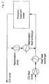
- Fig. 2 is a diagrammatic representation of a recirculation principle according to the present invention.
- the material to be treated is loaded into the pressure treatment vessel.
- the pressure treatment vessel is pressurised up to the desired operating pressure by feeding CO 2 to the pressure vessel by the CO 2 feed pump.
- the temperature of the feed is controlled by the feed heat exchanger.
- the pressure treatment vessel is depressurised by withdrawing CO2 from the vessel to the CO 2 outlet in a controlled manner.
- a pressure below 70 bars such as below 60 bars, preferable below 40 bars, and advantageously from a pressure below 2 bars
- part of the CO 2 in the pressure treatment vessel is withdrawn from the vessel to a re-circulation loop by the re-circulation pump, and returned to the pressure vessel after optionally passing a re-circulation heat exchanger for controlling the temperature in the vessel.
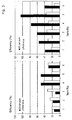
- Fig. 3 shows results from a supercritical wood impregnation process, which is further exemplified in the examples 1 and 2.
- a porous item to be impregnated is divided into two identical pieces so as to eliminate any effect of variations in the material to be treated.
- the reference items is first impregnated with an impregnation chemical at a substantially constant pressure of 150 bar and a temperature of 50 °C.
- the efficiency of the impregnation process is evaluated by the impregnation efficiency defined as the amount of the impregnation chemical present in the CO 2 phase compared to the amount of the impregnation chemical deposited in the items after treatment.
- the pressure vessel is first pressurised up to the reference conditions of approximately 150 bars and 50 °C, whereafter the vessel is depressurised to 130 bars under substantially constant temperature, whereafter the pressure vessel is pressurised again to 150 bars using the approximately the same concentration of the impregnation chemical in the CO 2 in the vessel. After the pressurisation, the pressure vessel is depressurised in a controlled manner. As seen from the left figure no significant effect on the impregnation efficiency is observed.
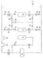
- Fig. 4 shows a typical industrial multi vessel process i.e where several extraction vessels are used sequentially in parallel. However, for simplificity only 2 vessels (8, 18) are shown. The operating procedure is only described for the extraction vessel (8), and the procedure will be similar for the extraction vessel (18).
- the extraction vessel (8) is loaded with the material to be extracted. Liquid carbon dioxide is stored in the storage tank (1). Liquid CO 2 is transferred from the storage tank (1) via the pump (2) and the valve (3) to the intermediate storage tank (4).
- liquid CO 2 from the intermediate storage tank (4) is transferred by the pump (6) to the extraction vessel (8), if the valve (5) is open.
- the liquid CO 3 is evaporated and the temperature of the gaseous CO 2 is controlled.
- the pressurization of the extraction vessel (8) by means of the pump (6) and the evaporator (7) is continued until the operating pressure in the supercritical region is reached.
- the cyclic supercritical extraction process is now performed by expanding CO 2 through the control valve (9), adjusting the temperature in the heat exchanger (10) and further expanding the CO 2 through the valve (11) and subsequently separating the extracted material in the separation units (12, 13). Subsequently the CO 2 is liquefied in the condenser (14) and returned to the intermediate storage (4), from where it is transferred back into the extraction vessel via the pump (6) and the evaporator (7).
- Supercritical CO 2 is thus continuously circulated through the extraction vessel (8) for the required amount of time to reach the required extraction yield.
- the vessel (8) are depressurized. This is in the prior art process accomplished by opening valves (15, 16).
- the pressure in vessel (18) is substantial ambient pressure and by opening the valves (15, 16) the pressures between vessels (8, 18) are equalized.
- the CO 2 is cooled and to avoid formation of liquid CO 2 or dry ice, heat has to be added in the heat exchangers (7, 17).
- vessel (8) Further emptying of vessel (8) is accomplished by extracting CO 2 from vessel (8) via the valves (9, 19) and the compressor (20). As the temperature of the CO 2 is increased during compression, the CO 2 gas stream has to be cooled in heat exchanger (17) before entering the vessel (18).
- a disadvantage of such prior art process is that the energy consumption is high due to the liquefaction of the fluid and due to the need for re-heating the fluid before entering the pressure vessel. Further equipment costs are increased due to a high heat transfer area required in the condenser and in the heating/cooling system compared to the present invention.
- a further disadvantage of such prior art process is the fact that the rate of pressurization and depressurization of the vessels cannot be controlled independently as two vessels at all times are interconnected. Generally by transferring CO 2 directly from one vessel to the next, the possibility of optimizing both pressurization and depressurization rates independently are lost.
- Fig. 5 illustrates the principles of an industrial scale supercritical process for the extraction of Tri-Chloro-Anisole (TCA) from cork according to the present invention.
- TCA represents a major quality problem for wines stored in bottles with cork stoppers due to the development of the so-called "cork taste”. Development of cork taste may destroy the wine and make it undrinkable.
- process comprises several extraction lines operating in parallel as indicated in the figure.
- a process according to the present invention comprises 2-6 lines operating sequentially in different stages of the cyclic process.
- the various lines share some major components, such as the buffer tank (1), the control valves (17), (18), the condenser (19), the heat exchanger (2), and the compressors (21), (23). These shared components are described in details below. For simplification only one vessel is shown in the figure.
- CO 2 is stored/recovered in a common buffer tank (1) shared between several extraction lines as indicated on the figure.
- the pressure in the buffer tank (1) will typically be in the range 50-70 bars, and preferably at a pressure of approximately 60 bars.
- the level of the liquid CO 2 in the buffer tank (1) is controlled by pumping liquid CO 2 from a make up tank (not shown in the drawing), and the pressure is controlled by controlling the temperature in the buffer tank (1).
- gaseous CO 2 is drawn from buffer tank (1) and piped at a predetermined rate through a heat exchanger (2), valve (3), heat exchanger (4), and valve (5).
- liquid CO 2 may also be withdrawn from the buffer tank through the valve (26), the pump (27) and the valve (28).
- Withdrawing gaseous CO 2 from the buffer tank (1) generates an evaporative cooling in the buffer tank (1), which is further described below.
- From a pressure of about 2 bar part of the CO 2 in the vessel is withdrawn and re-circulated by the compressor (9).
- the CO 2 from the compressor (9) is mixed with the CO 2 from the buffer tank (1) after the valve (3).
- valve (3) is closed and valve (8) is opened and the compressor (9) is used to compress the gaseous CO 2 from approx. 60 bar to the final supercritical pressure for the extraction, which typically is 120 bar.
- the compressor (9) operates and provides a large re-circulation rate through the vessel (6).
- the extraction process is accomplished by purging typically 10-100 kg CO 2 per kg cork granulate through the vessel (6) at a temperature of typically 60° C.
- the CO 2 exiting vessel (6) is expanded through the valve (7) reheated in the heat exchanger (10) and expanded through the valve (11).
- TCA and other components like waxes are removed in the separators (12, 13) whereupon the CO 2 is cleaned for residual content of TCA in an active carbon filter (14).
- the CO 2 exiting the carbon filter (14) is recompressed in the compressor (9) and the temperature controlled in the heat exchanger (4) to provide the required pressure and temperature for the extraction in the vessel (6).
- CO 2 When depressurising the vessel (6) vapour phase CO 2 is piped in a controlled manner through valve (15), valve (16).
- the major part of the CO 2 is generally entering the buffer tank (1) through valve (17), from where it is condensed by direct spraying into the liquid CO 2 phase in the buffer tank (1).
- Part of the CO 2 pass through the valve (18) into the condenser (19), where the CO 2 gas is liquefied before entering the buffer tank (1).
- the heat As heat is generated from the direct condensation in the buffer tank (1), the heat needs to be removed in order maintain a substantially constant temperature in the buffer tank (1). This is done by balancing the heat consumed by the evaporative cooling generated from the gas being withdrawn from the buffer tank (1). This balancing of the temperature in the buffer tank is performed by
- the buffer tank (1) needs to have a certain volume in order to work properly as a buffer tank, and in order to damp potential fluctuations of the temperature and pressure in the tank.
- the volume of the buffer tank compared to the total system volume of all lines (excluding the buffer tank (1)) is generally in the range 50-300 %, and preferably in the range 100-150 %.
- the valve (24) is closed during this operation to ensure that no back flow occurs.
- the compressor (21) will generally be a one-stage compressor. After the compressor the CO 2 is discharged to the buffer tank (1) through the valves (17) and/or (18) and heat exchanger (19) as described above for the pressure range 120-60 bars. It should be noticed that depressurisation from 60 to a pressure in the range 20-30 bars also could be performed using the re-circulation compressor (9), but a system of two compressors is generally preferred due to capacity and redundancy considerations.
- the depressurisation of the vessel from a pressure in the range 20-30 bars to a pressure in the range 2-6 bars (6) is performed through the valve (22) by the compressor (23).
- the CO 2 is again discharged to the buffer tank (1) through the valves (17) and/or (18) and heat exchanger (19) as described above.
- the final depressurisation is performed by venting off the fluid vessel to the atmosphere (not shown).
- the pressure for this depressurisation step is set by the desired recovery of the CO 2 . If a high CO 2 recovery is desired, the pressure for the final stage will typically be in the range 1-3 bars above ambient pressure.
- the compressor (23) will comprise a three stage compressor. If a lower CO 2 recovery is desired, the compressor (23) may comprise a 2 stage compressor.
- the compressors (21, 23) are generally only in used in a limited part of cyclic process, such as 10-35 % of the total cycle time. As such compressors are relatively expensive the compressors (21, 23) are preferably shared between several extraction lines as indicated in the figure. It should further be noticed that the compressors (21, 23) may comprise more than one compressor operating in the same pressure range in order to fulfil redundancy or economical demands.
- Fig. 6 shows a diagrammatic representation of a process layout suitable for operating any combination of steps of a supercritical extraction step, a supercritical impregnation step, a particle formation step, and/or a curing step at an elevated temperature.
- this process diagram further comprise a mixer vessel (29) in the re-circulation loop for addition of chemical(s), and/or cosolvent(s)and/or surfactants.
- the mixer is preferably containing a high surface area packing material so as to provide a high contact area for addition of said chemical(s), and/or cosolvent(s), and/or surfactant(s).
- said chemical(s), cosolvent(s) and/or surfactant(s) may be added to the same vessel but said re-circulation loop may comprise more than one mixer for addition of said chemical(s), and/or cosolvent(s) and/or surfactants separately.
- the conventional supercritical impregnation process includes 3 consecutive steps:
- the material to be treated is introduced into a pressure vessel.
- the vessel is pressurized by adding a fluid to the reactor, until the pressure in the vessel exceeds the desired pressure of said fluid.
- the temperature of the fluid may be controlled by conventional means before the introduction into the vessel, and the temperature in the reactor is further controlled by controlling the wall temperature, to a level exceeding the desired temperature of the fluid.
- the enclosed fluid in the vessel enters the supercritical state, and the impregnation compounds become soluble in the fluid.
- pressurisation of the vessel is achieved by introducing fluid, and as the fluid by definition is compressible, further compression of the fluid takes place in the vessel.
- the derived heat of compression is dissipated in the materials enclosed in the reactor, and finally removed through the reactor walls.
- the heat of compression may lead to a significant temperature increase.
- the second step is a treatment at practically constant temperature and pressure, during which impregnation compounds are distributed throughout the material to be impregnated. Furthermore, during this step the heat of compression is dissipated to the vessel walls, if sufficient residence time is allowed, establishing the intended temperature throughout the reactor.
- depressurisation is conducted in the third step, by controlled evacuation of the fluid from the vessel. The expansion of the fluid leads to reduced solubility of the impregnation compounds, which therefore precipitate at the internal surfaces of the porous material, providing the intended impregnation.
- the energy required to expand the fluid is taken from the remaining fluid, and the other materials in the reactor, and finally balanced by heat introduced through the reactor walls.
- the pressure and temperature are maintained practically constant. Consequently distribution of the impregnation compounds in the porous material to be impregnated is mainly due to diffusion, as no convective supercritical solvent flow exists inside the porous material.
- a pressure pulsation may be induced during the impregnation period, creating a convective flow inside the porous structures.
- the pressure pulsation is preferably induced by a pulsation of the supercritical solvent inlet temperature, i.e.
- a further benefit from the pressure pulsation during the impregnation period may be derived in the case where the lower limit of the cyclic pressure pulsation is below the solubility limit of the impregnation compounds at the applied temperature and intended concentration of impregnation compounds in the supercritical solvent.
- the solubility of a substance in a supercritical solvent is to a first approximation determined by the solvent temperature and density, i.e. by reactor temperature and pressure.
- the solubility limit is defined as the lower pressure at a certain temperature, at which the intended amount of a substance is soluble. If the pressure is reduced below this limit, precipitation takes place.
- the expected deposition of the compound is calculated as the concentration dissolved in the bulk solvent phase, multiplied with the solvent volume entrapped in the wood at impregnation conditions, i.e. the deposition achieved if the total amount of solvent introduced into the wood was carrying a full load of impregnation compound.
- the impregnation efficiency is defined as the ratio of the measured deposition to the expected deposition.
- Impregnation with pulsation below the solubility limit is shown in the right part of the figure, and denoted "30 bar peak”. The effect of pulsation below the solubility limit is significant. The impregnation efficiency is doubled, when compared to the reference logs.
- One aspect of the present invention involves a cyclic process for supercritical extraction treatment of materials.
- the material to be treated by the supercritical extraction process is initially loaded in to a pressure vessel.
- the cyclic process is initiated by purging the vessel with the specific fluid used in the cyclic process in order to minimize contamination of the fluid.
- This purging may be conducted by applying a vacuum (pressure below ambient pressure) to the vessel, while feeding the specific fluid to the vessel for a certain period of time. Typically this purging time will be in the range 1-20 minutes. In other cases this purging may be performed by pressurisation of the vessel up to a pressure of 0,5-5 bars above ambient pressure and venting the vessel until the pressure is substantially the same as ambient pressure. It should be understood that any combination of purging using a vacuum and venting from a pressure above ambient pressure may be applied and that this procedure may be repeated.
- the vessel is pressurised by the specific fluid at a predetermined inlet temperature to the vessel and a predetermined rate of pressure increase in the vessel.
- the inlet temperature to the vessel will be controlled to achieve a temperature within the pressure vessel above the condensation temperature of the specific fluid, and below a certain maximum temperature dictated by the material to be treated in the vessel.
- the inlet temperature of supercritical fluid is typically controlled in the range 0-200 °C, such as 0-150°C, and preferably in the range 15-100 °C and more preferably in the range 35-60 °C during pressurization.
- the set point for the inlet temperature may be constant during the pressurisation period, but in many applications according to the present invention the inlet temperature is increasing during the pressurisation period.
- control of temperature within the vessel is critical for many applications.
- temperature control is performed by control of inlet temperature and/or control of the inlet and outlet temperature of a heating or cooling fluid fed to a jacketed vessel.
- applying such systems for large diameter vessels creates temperature gradients within the vessels as the heat transfer area is not large enough to ensure sufficient heat transfer capacity.
- part of the fluid is withdrawn from the vessel in at least part of the pressurisation period, and fed to an external re-circulation loop comprising at least one heat exchanger for adding or extracting heat from the fluid, where after the fluid is re-circulated to the pressure vessel after conditioning. It is further preferred that the fluid do not undergo a phase change in the external re-circulation loop during the pressurisation period.
- the withdrawing of the fluid from the vessel to the external re-circulation loop is preferably performed from a pressure below 40 bars such as a pressure below 20 bar, and advantageous at a pressure below 2 bars.
- the fluid flow withdrawn needs to have a certain size.
- the fluid flow corresponds to replacement of at least one vessel volume per hour, such as at least 5 vessel volumes per hour, and preferably at least 10 vessel volumes per hour and more preferably between 10-50 vessel volumes per hour and advantageously in the range 10-20 vessel volumes per hour.
- the rate of pressure increase is typically in the range 0,05-100 bar/min, such as 0,1-20 bar/min and preferably in the range 0,1-15 bar/min, such as in the range 0,2-10 bar/min.
- the rate of pressure increase may be constant or vary during the pressurisation period.
- means for pressurisation have a constant volumetric flow rate.
- the maximum mass flow rate of said means increases with the density of the fluid used for pressurisation.
- the rate of pressure increase will vary with the fluid density if said means were operating at maximum capacity during the pressurisation period.
- the rate of pressure increase may also be obtained by increasing the temperature to the vessel or by a combination of the two.
- one aspect of the present invention involves controlling the rate of pressurisation and the temperature in specific pressure intervals during the pressurisation period, while operating higher rates outside this interval.
- the rate of pressure increase is particularly critical in the pressure range from 40 to 120 bars, such as in the range 60 to 110 bars, and in particular in the range 65 to 100 bars.
- the rate of pressurisation in at least part of the interval 40 to 120 bars is at the most one half of the maximum rate of pressurisation outside this range, such as one third of the maximum rate of pressurisation, and preferably at the most one fifth of the maximum rate of pressurisation, and more preferably at the most one tenth of maximum rate of pressurisation outside this pressure range.
- the majority of the fluid fed to the vessel is CO 2 .
- it may also comprise other fluids such as one or more co-solvents, one or more surfactants or impurities such as air and/or water and/or traces of the extracted compounds.
- surfactants can be found in the prior art e.g. WO9627704 and EP0083890 , which hereby with respect to disclosure concerning surfactants and their preparation are incorporated herein by reference.
- the temperature and pressure during the holding period for extraction depend of the specific substrate to be treated and the species to be extracted.
- suitable co-solvents are water, ethane, ethylene, propane, butane, sulfurhexafluoride, nitousoxide, chlorotrifluoromethane, monofluoromethane, methanol, ethanol, DMSO, isopropanol, acetone, THF, acetic acid, ethyleneglycol, polyethyleneglycol, N,N-dimethylaniline etc. and mixtures thereoff.
- the pressure during the holding period for extraction will typically be in the range 85-500 bar.
- the target temperature during the extraction period will typically be 35-200 °C such as 40-100 °C.
- the extraction fluid may be further purified in an activated carbon filter before re-circulation to the pressure vessel.
- the duration of the holding period for extraction will typically be in the range 5-300 minutes.
- the re-circulation flow rate during the holding period needs to be of a certain size in order to enhance mass transfer and to obtain a substantially uniform extraction quality in the whole pressure vessel.
- the fluid flow withdrawn corresponds to replacement of at least one vessel volume per hour, such as at least 5 vessel volumes per hour, and preferably at least 10 vessel volumes per hour and more preferably between 10-50 vessel volumes per hour and advantageously in the range 10-20 vessel volumes per hour.
- the vessel After the pressurisation period, the vessel is depressurised at a controlled temperature and rate of depressurisation.
- part of the fluid is withdrawn from the vessel in at least part of the depressurisation period, and fed to an external re-circulation loop comprising at least one heat exchanger for adding or extracting heat from the fluid, where after the fluid is re-circulated to the pressure vessel after conditioning. It is further preferred that the fluid do not undergo a phase change in the external re-circulation loop during the depressurisation period.
- the inlet temperature in at least part of the depressurisation period may advantageously be increased compared to the inlet temperature of the holding in order to compensate for the considerable cooling arising from the expansion.
- the inlet temperature during depressurisation may be increased by up to 10 °C, such as up to 25 °C compared to the inlet temperature during the holding period.
- the actual inlet temperature during depressurisation will typically be maintained in the range 35-70 C at pressures above 40 bars.
- the re-circulation flow rate during the depressurisation period needs to be of a certain size in order to ensure substantially uniform pressure-, temperature-and density conditions within the vessel.
- the fluid flow withdrawn during the depressurisation period corresponds to replacement of at least one vessel volume per hour, such as at least 5 vessel volumes per hour, and preferably at least 10 vessel volumes per hour and more preferably between 10-50 vessel volumes per hour and advantageously in the range 10-20 vessel volumes per hour.
- the rate of depressurisation is typically in the range 0,05-100 bar/min, such as 0,1-20 bar/min and preferably in the range 0,1-15 bar/min, such as in the range 0,2-10 bar/min.
- the rate of depressurisation in at least part of the pressure interval below 110 bars is at the most one half of the maximum rate of depressurisation outside this range, such as one third of the maximum rate of depressurisation, and preferably at the most one fifth of the maximum rate of depressurisation, and more preferably at the most one tenth of maximum rate of depressurisation outside this pressure range.
- the depressurisation period may further comprise one or more holding periods at constant pressure in which the pressure and temperature conditions inside the material is allowed to stabilise.
- the expanded fluid In the pressure interval above 2-5 baro the expanded fluid is typically recovered for reuse. Below a pressure below 5 baro such as below 2 baro, the fluid is typically vented off at a controlled depressurisation rate.
- the vessel Before opening the pressure vessel and unloading the material, the vessel is generally purged with air in order to avoid any exposure risk by the fluid, when opening the vessel.
- This purging may be conducted by applying a vacuum (pressure below ambient pressure) to the vessel, while feeding air to the vessel for a certain period of time. Typically this purging time will be in the range 1-20 minutes. In other cases this purging may be performed by pressurisation of the vessel with air up to a pressure of 0,5-5 bars above ambient pressure and venting the vessel until the pressure is substantially the same as ambient pressure. It should be understood that any combination of purging using a vacuum and venting from a pressure above ambient pressure may be applied and that this procedure may be repeated.
- Horhota et al discloses a pressure modulation technique, where repeated pressure pulses of less than 30 % relative difference between the uppermost and lowermost pressure levels are applied in an attempt to overcome the drawbacks of the large pressure pulse techniques.
- Small pressure pulses according EP 1,265,583 may provide enhanced mixing in bulk phase, and may be suitable for applications such as supercritical parts cleaning. However, small pressure pulses will not create the desired significant pumping effect, when applied for low permeability materials such as micro- or nanoporous materials.
- a further objective of the present invention is to provide a method for improving the mass and heat transfer in a cyclic dense fluid extraction process not suffering the drawbacks in the prior art.
- the uppermost and lowermost levels of the inlet temperature is selected so as to provide a density change between the uppermost and the lowermost level of up 75 %, such as up to 50 %, and preferable up to 30 %.
- the temperature modulation is generally performed at least two times and may be repeated multiple times such as 5-100 times.
- the volume of the fluid withdrawn from the pressure vessel needs to be of a certain size such as corresponding to replacement of at least 5 vessel volumes per hour and preferably in the range 10-50 vessel volumes per hour such as replacement of 10-20 vessel volumes per hour
- the temperature modulation is in particular effective for enhancing mass- and heat transfer efficiency for a supercritical extraction process during the holding period.
- temperature modulation also be applied in the pressurisation and/or the depressurisation period for minimisation of the temperature-and/or pressure gradients between the bulk phase and the centre of a confined space. This particularly relevant in relation to the treatment of low permeability materials containing confined spaced in a micro- or nanoporous structure.
- the temperature modulation of the inlet temperature is performed in combination with a pressure pulsation technique.
- said temperature modulation is performed during the holding period and combined with an overall pressure control loop for maintaining the pressure in the pressure vessel substantially constant by adding or extracting fluid to/from the pressure vessel.
- the temperature modulation of the inlet is combined with a pressure modulation or pressure pulsation technique, wherein the lowermost pressure level are obtained at substantially the same time as the uppermost temperature level and vice versa.
- Another aspect of the present invention involves supercritical treatment of polymers containing impurities such as excess monomers and/or solvents from the polymerisation reaction.
- impurities such as excess monomers and/or solvents from the polymerisation reaction.
- Other undesired impurities may be compounds resulting in an unpleasant smell, or compounds limiting the further processing of the materials, such as reduced adhesion.
- Examples of such components are extender oils, and/or organic acids present in recycled vulcanised rubbers.
- such treatment of polymers which undergoes a supercritical extraction process as described in example 3 and 4 in order to remove the undesirable residues, and make the materials suitable for further processing.
- the removal of these components makes the polymer matrix more porous and more accessible for e.g. modification by reactive impregnation or adhesive.
- Another aspect of the present invention involves the supercritical treatment of a material as described in the examples 3-6, wherein the material subsequent to the holding period for extraction, further undergoes a holding period for impregnation prior to the depressurisation period.
- Said impregnation period is preferably performed at substantially the same average pressure as for the extraction period.
- the chemicals may be added to the mixer vessel at the beginning of the cyclic process, or at any part of the cyclic process.
- part of the fluid is continuously withdrawn from the pressure vessel and fed to a re-circulation loop comprising one or more heat exchanger(s) for addition or extraction of heat, and re-circulated to the pressure vessel.
- the inlet temperature to the vessel is modulated between two or more temperature levels in order to provide a modulation in the fluid density within the vessel, while an overall control loop is maintaining the pressure within the pressure vessel substantially constant by adding or extracting fluid to/from the pressure vessel.
- Supercritical fluids are excellent solvents for reactive particle formation, leading to nano-particle products with very narrow size distribution.
- the basis of the reactive particle formation method is a chemical system, in which reactants are soluble in the solvent utilized, while the reaction products are insoluble.
- An example of such system is metal oxides, formed from reaction between metal alcoholates and water. Due to the insolubility of the product the chemical reaction rapidly produces a supersaturated product solution, and hence precipitation starts to take place in the reaction vessel. The precipitation is initiated at, and grows from, any available nucleation site, i.e. vessel walls or seed particles present in the vessel. Precipitation, and accordingly particle growth, continues until the solution is no longer supersaturated.
- nucleation sites are provided in the reaction vessel, precipitation time and thereby particle growth is restricted, and very small particles - in the nano-meter range - with a very narrow size distribution and high degree of crystalinity are formed.
- ways to introduce the nucleation sites to the reaction vessel are addition of seed particles or a filling material.
- precipitation time In order to ensure the narrow particle size distribution, precipitation time must be controlled accurately, i.e. super-saturation must be achieved in all parts of the vessel at the same time.
- super-saturation i.e. super-saturation must be achieved in all parts of the vessel at the same time.
- the mixing of reactants must be homogenous
- the chemical reaction should be relatively fast compared to the.precipitation time
- the solvent properties should be carefully controlled to ensure homogenous solubility throughout the vessel. Both reactant mixing and solvent property control are facilitated through the circulation loop of the present invention.
- treatment lines mentioned treatment processes or just lines.
Landscapes
- Chemical & Material Sciences (AREA)
- Life Sciences & Earth Sciences (AREA)
- Chemical Kinetics & Catalysis (AREA)
- Engineering & Computer Science (AREA)
- Organic Chemistry (AREA)
- Analytical Chemistry (AREA)
- Wood Science & Technology (AREA)
- Forests & Forestry (AREA)
- Inorganic Chemistry (AREA)
- Physics & Mathematics (AREA)
- Acoustics & Sound (AREA)
- Nanotechnology (AREA)
- Mechanical Engineering (AREA)
- Extraction Or Liquid Replacement (AREA)
- Physical Or Chemical Processes And Apparatus (AREA)
- Solid-Sorbent Or Filter-Aiding Compositions (AREA)
- Casting Or Compression Moulding Of Plastics Or The Like (AREA)
- Processing Of Solid Wastes (AREA)
- Control Of Heat Treatment Processes (AREA)
- Chemical And Physical Treatments For Wood And The Like (AREA)
- Treatment Of Liquids With Adsorbents In General (AREA)
- Devices And Processes Conducted In The Presence Of Fluids And Solid Particles (AREA)
- Processing And Handling Of Plastics And Other Materials For Molding In General (AREA)
- Filling Or Discharging Of Gas Storage Vessels (AREA)
- Food Preservation Except Freezing, Refrigeration, And Drying (AREA)
- Separation, Recovery Or Treatment Of Waste Materials Containing Plastics (AREA)
Claims (56)
- Verfahren zur Behandlung eines Materials, das in einem Gefäß enthalten ist, wobei das Verfahren ein Fluid einbezieht, das in dem Gefäß verhanden ist, und mindestens einen Druckbeaufschlagungsschritt, bei dem der Druck in dem Gefäß erhöht wird, und mindestens einen Druckablassungsschritt, bei dem der Druck in dem Gefäß gesenkt wird, umfasst, wobei das Verfahren weiterhin Rückführen mindestens eines Teils des Fluids für mindestens einen Teil der Dauer des Verfahrens umfasst, wobei das Rückführen umfasst: Abziehen mindestens eines Teils des Fluids, das in dem Gefäß enthalten ist, aus dem Gefäß und Einspeisen desselben in eine Rückführungsschleife und anschließendes Einspeisen des Fluids in das Gefäß, wobei sich das Fluid nach dem Druckbeaufschlagungsschritt in einem superkritischen Zustand befindet, und wobei das Rückführen während des Druckbeaufschlagungsschritts und/oder während des Druckablassungsschritts durchgeführt wird,
dadurch gekennzeichnet, dass das Fluid, das in der Rückführungsschleife vorhanden ist, keinen Phasenübergang in einen flüssigen oder festen Zustand durchmacht. - Verfahren nach Anspruch 1, weiterhin umfassend einen Verweilschritt, in dem der Druck in dem Gefäß im Wesentlichen konstant ist und/oder in dem der Druck des Fluids in dem Gefäß während einer Verweildauer mit vorbestimmter Länge gemäß einem vorgewählten Plan verändert wird.
- Verfahren nach Anspruch 2, wobei das Fluid während der Verweilzeit in superkritischen Zuständen ist.
- Verfahren nach einem der Ansprüche 1-3, weiterhin umfassend den Schritt des Steuerns der Temperatur des Fluids in der Rückführungsschleife.
- Verfahren nach einem der vorhergehenden Ansprüche, wobei dem Fluid in der Rückführungsschleife Wärme zugeführt und/oder entzogen wird.
- Verfahren nach einem der vorhergehenden Ansprüche, wobei das Verfahren Temperatur-, Druck und/oder Dichteprofile innerhalb des Gefäßes steuert.
- Verfahren nach einem der vorhergehenden Ansprüche, wobei das Fluid ausgewählt ist aus der Gruppe, bestehend aus Kohlendioxid, Alkohol, Wasser, Methan, Ethan, Ethylen, Propan, Butan, Pentan, Hexan, Cyclohexan, Toluol, Heptan, Benzol, Ammoniak, Schwefelhexafluorid, Distickstoffoxid, Chlortrifluormethan, Monofluormethan, Methanol, Ethanol, DMSO, Propanol, Isopropanol, Aceton, THF, Essigsäure, Ethylenglycol, Polyethylenglycol, N,N-Dimethylanilin usw. und Mischungen davon.
- Verfahren nach einem der vorhergehenden Ansprüche, wobei das Fluid Kohlendioxid ist.
- Verfahren nach einen der vorhergehenden Ansprüche, wobei das Fluid weiterhin mindestens ein Mitlösungsmittel umfasst.
- Verfahren nach einem der vorhergehenden Ansprüche, wobei das Fluid nach dem Druckablassungsschritt in einem gasförmigen und/oder flüssigen und/oder festen Zustand vorliegt.
- Verfahren nach einem der Ansprüche 1-10, wobei ein Teil des Fluids in dem Druckgefäß bei einem Druck in dem Druckgefäß von unter 70 bar in die Rückführungsschleife abgezogen wird.
- Verfahren nach einem der vorhergehenden Ansprüche, wobei das Fluidvolumen, das aus dem Gefäß abgezogen wird, dem Austausch von mindestens einem Gefäßvolumen pro Stunde entspricht.
- Verfahren nach einem der vorhergehenden Ansprüche, wobei cer Druck in dem Gefäß nach dem Druckbeaufschlagungsschritt im Bereich 85-500 bar liegt.
- Verfahren nach einem der vorhergehenden Ansprüche, wobei die Temperatur in dem Gefäß im Bereich 20-300 °C gehalten wird.
- Verfahren nach einem der vorhergehenden Ansprüche, wobei die Rate der Druckbeaufschlagung und/oder der Druckablassung auf eine vorherbestimmte Weise mit bestimmten Druckintervallen während des Zeitraums der Druckbeaufschlagung / Druckablassung gesteuert wird.
- Verfahren nach Anspruch 11, wobei die Rate der Druckerhöhung in wenigstens einem Teil des Druckbereichs von 40 bis 120 bar höchstens die Hälfte der Höchstrate der Druckbeaufschlagung außerhalb dieses Bereichs beträgt.
- Verfahren nach einem der vorhergehenden Ansprüche, wobei die Temperatur des Fluids, das während der gesamten Verweildauer oder eines Teils davon in das Gefäß eingespeist wird, gemäß einen vorherbestimmten Plan variiert, um Druckschwarkungen einzuführen, die den Temperaturschwankungen in dem Gefäß entsprechen.
- Verfahren nach Anspruch 17, wobei das höchste und das niedrigste Temperaturniveau gewählt sind, um eine Dichteänderung zwischen dem höchsten und dem niedrigsten Niveau von bis zu 75 % bereitzugestellen.
- Verfahren nach einem der Ansprüche 2-18, wobei die Rückführungsschleife weiterhin ein Mischgefäß zum Vermischen des Fluids mit Chemikalien, das einem Wärmetauscher nachgeordnet angeordnet ist, umfasst.
- Verfahren nach einem der vorhergehenden Ansprüche, wobei das Verfahren weiterhin mindestens einen Schritt eines Extrahierens von Bestandteilen aus dem Material, das in dem Gefäß enthalten ist, umfasst, wobei das Extrahieren Steuern des thermodynamischen Zustands in dem Gefäß umfasst, um so einen vorgewählten Zustand, in dem Extrahieren von Bestandteilen stattfindet, zu erhalten.
- Verfahren nach Anspruch 20, wobei die Temperatur in dem Gefäß während des Extrahierens von Bestandteilen aus dem Material, das in dem Gefäß enthalten ist, im Bereich 70-140 °C liegt und wobei der Druck in dem Gefäß während des Extrahierens von Bestandteilen aus dem Material, das in den Gefäß enthalten ist, im Bereich 100-500 bar liegt.
- Verfahren nach Anspruch 20 oder 21, wobei das Verhältnis der Menge an CO2, das verwendet wird, um die Bestandteile aus dem Material, das in dem Gefäß enthalten ist, zu extrahieren, zu der Menge an Material, das in dem Gefäß enthalten ist, im Bereich von 1 kg/kg bis 80 kg/kg liegt.
- Verfahren nach einem der Ansprüche 20-22, wobei der thermodynamische Zustand in dem Gefäß gesteuert ist, um eine selektive Extraktion von Bestandteilen aus dem Material, das in dem Gefäß enthalten ist, zu erreichen, während andere extrahierbare Bestandteile in dem Material behalten bleiben.
- Verfahren nach Anspruch 23, wobei das Verfahren nachfolgende Extrahierschritte umfasst, wobei der thermodynamische Zustand in jeden Schritt gesteuert ist, um einen vorgewählten Zustand zu erhalten, in dem eine vorgewählte Extraktion von Bestandteilen aus dem Material in dem Gefäß stattfindet.
- Verfahren nach Anspruch 24, wobei der thermodynamische Zustand in dem ersten Schritt gewählt wird, um die Gesamtmenge an Extrakt, das in dem ersten Schritt entfernt wird, verglichen mit der Gesamtmenge an Extrahierbarem im Bereich 10-35% zu wählen, wobei die Gesamtmenge an Extrahierbarem beispielsweise mittels des SOXLETH-Verfahrens (ASTM D1416) unter Verwendung von Pentan als Lösungsmittel bestimmt wird.
- Verfahren nach Anspruch 24 oder 25, wobei der thermodynamische Zustand in dem ersten Schritt gesteuertist, sodass die Temperatur in dem Gefäß im Bereich 65-100 °C liegt, und gesteuert ist, sodass der Druck in dem Gefäß im Bereich 100-200 bar liegt.
- Verfahren nach einem der Ansprüche 24-26, wobei der thermodynamische Zustand in dem zweiten Extraktionsschritt gesteuert ist, sodass die Temperatur in dem Gefäß im Bereich 80-140 °C liegt, und gesteuert ist, sodass der Druck in dem Gefäß im Bereich 200-300 bar liegt.
- Verfahren nach einem der Ansprüche 20-27, wobei das Verfahren weiterhin mindestens einen Schritt des Extrahierens von Bestandteilen aus dem Material, das in dem Gefäß enthalten ist, umfasst, das Extrahieren umfasst:- Steuern des thermodynamischen Zustands in dem Gefäß, um einen vorgewählten Zustand, in dem die Extraktion von Bestandteilen stattfindet, zu erhalten,- Abziehen mindestens eines Teils des Fluids, das in dem Gefäß enthalten ist, aus dem Gefäß während des Schritts bzw. der Schritte des Extrahierens von Bestandteilen aus dem Material, das in dem Gefäß enthalten ist, und Einspeisen desselben in eine Rück-führungsschleife zum Abtrennen von extrahierten Bestandteilen von dem Fluid,- mindestens teilweises Abtrennen der extrahierten Bestandteile von dem Fluid bei einem Druck oberhalb des kritischen Drucks des Fluids,- Einspeisen des abgetrennten Fluids in das Gefäß.
- Verfahren nach Anspruch 28, wobei der Druck in dem Gefäß für das Extrahieren von Bestandteilen mindestens 150 bar beträgt.
- Verfahren nach Anspruch 29, wobei der Druck für das Abtrennen der extrahierten Bestandteile von dem Fluid mindestens 1/2 des Drucks in dem Gefäß für das Extrahieren von Bestandteilen beträgt.
- Verfahren nach einem der Ansprüche 28-30, wobei der thermodynamische Zustand zum Abtrennen gesteuert ist, sodass die Löslichkeit der extrahierten Bestandteile in dem Fluid maximal 20 % der Löslichkeit der extrahierten Bestandteile bei dem Druck in dem Gefäß für das Extrahieren von Bestandteilen beträgt.
- Verfahren nach einem der vorhergehenden Ansprüche, wobei das Verfahren weiterhin mindestens einen Imprägnier- oder Beschichtungsschritt zum Imprägnieren des Materials, das in dem Gefäß enthalten ist, umfasst, wobei der Imprägnier- oder Beschichtungsschritt Steuern des thermodynamischen Zustands in dem Gefäß umfasst, um so einen vorgewählten Zustand zu erhalten, in dem Imprägnierbestandteil(e) das Material, das in dem Gefäß enthalten ist, imprägniert/imprägnieren oder beschichtet/beschichten.
- Verfahren nach Anspruch 32, wobei der Imprägnier-oder Beschichtungsschritt eine chemische Reaktion einbezieht.
- Verfahren nach Anspruch 33, wobei die Chemikalie(n), die in dem Imprägnier- oder Beschichtungsschritt verwendet wird bzw. werden, Vorstufen für eine chemische Reaktion sind.
- Verfahren nach Anspruch 32 oder 33, wobei die chemische Reaktion eine Silylierung ist.
- Verfahren nach einem der Ansprüche 32-35, wobei die Chemikalie bzw. den Chemikalien in im Wesentlichen einer Einzelschicht auf dem Material, das in dem Gefäß enthalten ist, imprägniert oder beschichtet wird bzw. werden.
- Verfahren nach einem der Ansprüche 32-36, wobei die Oberflächenbedeckung der Chemikalie(n) auf dem Material, das in dem Gefäß enthalten ist, mindestens 5 Moleküle/nm2 beträgt.
- Verfahren nach Anspruch 2-37, wobei die Verweildauer einen oder mehrere Extrahierschritte umfasst und wobei dem Extrahierschritt ein oder mehrere Imprägnierschritte folgen.
- Verfahren nach Anspruch 33, wobei die Verweildauer einen oder mehrere Extrahierschritte gefolgt von einem oder mehreren Imprägnierschritten umfasst, wobei dem Imprägnieren ein oder mehrere Schritte der Temperaturerhöhung folgen und wobei dem einen Schritt oder den mehreren Schritten der Temperaturerhöhung ein oder mehrere Schritte der Temperaturverminderung folgen.
- Verfahren nach Anspruch 39, wobei der letzte Schritt bzw. die letzen Schritte der Verweildauer einen oder mehrere Extrahierschritte umfasst bzw. umfassen und wobei überschüssige Imprägnierchemikalie(n) von dem einen oder den mehreren Imprägnierschritt(en) aus dem Material, das in dem Gefäß enthalten ist, in dem wenigstens einen oder den mehreren Extrahierschritten extrahiert wird bzw. werden.
- Verfahren nach einem der vorhergehenden Ansprüche, wobei das und/oder Fluid, das in dem Gefäß enthalten ist, bewegt wird bzw. werden und wobei das Verfahren weiterhin Sprühen von Beschichtungs- oder Imprägnierchemikalie(n) in das bewegte Gefäß während wenigstens eines Teils der Dauer des Druckablassungsschritts umfasst.
- Verfahren nach Anspruch 41, wobei die Beschichtungs- oder Imprägnierchemikalie(n) in das bewegte Gefäß gesprüht wird bzw. werden und in dem Fluid, das in dem Gefäß enthalten ist, im Wesentlichen unlöslich ist bzw. sind.
- Verfahren nach Anspruch 1-42, wobei mindestens ein erster Teil des Fluids, das während der Druckablassung aus dem Gefäß abgezogen wird, in einen Puffertank mit einem Ausgang, der entwoder direkt oder über die Rückführungsschleife, wo es kondensiert wird, mit dem Gefäß verbunden ist, eingespeist wird und wobei mindestens ein zweiter Teil des Fluids, das aus dem Gefäß abgezogen wird, in einen Kondensator eingespeist wird, wo es kondensiert wird, wobei das kondensierte Fluid nachfolgend in einen Puffertank mit einem Ausgang, der entweder direkt oder über die Rückführungsschleife mit dem Gefäß verbunden ist, eingespeist wird, wobei die Temperatur in dem Puffertank gesteuert wird, sodass sie im Wesentlichen konstant gehalten wird, wobei das Steuern mindestens teilweise durch Auftrennen des ersten und des zweiten Teils des Fluids, das aus dem Gefäß abgezogen und in den Puffertank eingespeist wird, erreicht wird, wodurch die Wärme ausgeglichen wird, die durch die Verdampfungskühlung verbrauchtund von dem Fluid erzeugt wird, das aus dem Puffertank durch den Ausgang davon abgezogen wird, und wobei das Steuern der Temperatur in dem Puffertank weiterhin Steuern des Flüssigkeitspegels in dem Puffertank durch Zugabe von Zusatzfluid aus einem Zusatzfluidtank umfasst.
- Verfahren nach Anspruch 43, umfassend verschiedene Behandlungslinien, die parallel und in verschiedenen Stadien des zyklischen Verfahrens arbeiten, und wobei die verschiedenen Behandlungslinien mit dem Puffertank verbunden sind und aufweisen:- gemeinsames Einspeisesystem bzw. gemeinsame Einspeisesysteme zur Druckbeaufschlagung,- gemeinsame Leitungen zur Druckablassung, einschließlich Kompressoren,- gemeinsamer Kondensator bzw. gemeinsame Kondensatoren,- gemeinsame Leitung bzw. Leitungen zum Sprühen des Fluids in die flüssige Phase,- gemeinsames Zusatzsystem bzw. gemeinsame Zusatzsysteme.
- Verfahren nach einem der Ansprüche 1-44, wobei das zu behandelnde Material Holz ist.
- Verfahren nach Anspruch 45, wobei das Holz mit einem organischen Fungizid oder einem organischen Insektizid imprägniert wird.
- Verfahren nach Anspruch 46, wobei das Holz mit Chemikalie(n) imprägniert wird, die Propiconazol enthält bzw. enthalten.
- Verfahren nach einem der Ansprüche 1-44, wobei das behandelte Material Kork ist.
- Verfahren nach einem der Ansprüche 1-44, wobei das zu behandelnde Material ein poröses Sorptionsmittel ist.
- Verfahren nach Anspruch 49, wobei das poröse Sorptionsmittel ausgewählt ist aus Aerogelen, Zeolithen, Silicagelen, Aktivkohlen, Siliciumoxiden, Aluminiumoxiden, Zirconiumoxiden, Titanoxiden.
- Verfahren nach Anspruch 49 oder 50, wobei das poröse Sorptionsmittel eine Porengröße im Bereich 5-100 nm aufweist.
- Verfahren nach einem der Ansprüche 49-51, wobei das poröse Sorptionsmittel mit einer Silanverbindung imprägniert wird.
- Verfahren nach einem der Ansprüche 49-52, wobei die Chemikalie(n) für den Imprägnier- oder Beschichtungsschritt ausgewählt ist bzw. sind aus Organosilanen, Alkoxysilanen, Chlorsilanen, Fluorsilanen, Octadecylsilanen, n Octadecyltriethoxysilan, n-Octadecyldimethylmethoxysilan, Perfluoroctyltriethoxysilan, Hexamethyldisilazan, Trichloroctadecylsilan, Mercaptopropylsilan, Mercaptopropyltrimethoxysilan, Ethylendiamin, Trimethoxysilan, Trimethylchlorsilan, ODDMS, Tetraethoxysilan.
- Vorrichtung zur Verwendung bei der Behandlung eines Materials, wobei die Vorrichtung ein Gefäß umfasst, das dazu eingerichtet ist, zu behandelndes Material und ein Fluid, das an der Behandlung beteiligt ist, zu enthalten, wobei die Vorrichtung weiterhin umfasst- Druckmittel zur Erhöhung/Verminderung des Drucks in dem Gefäß, um so mindestens einen Druckbeaufschlagungsschritt, bei dem der Druck in dem Gefäß erhöht wird, und mindestens einen Druckablassungsschritt, bei dem der Druck in dem Gefäß gesenkt wird, durchzuführen,- und eine Rückführungsschleife zum Rückführen mindestens eines Teils des Fluids, wobei die Rückführungsschleife dazu eingerichtet ist, mindestens einen Teil des Fluids, das in dem Gefäß enthalten ist, aus dem Gefäß abzuziehen und es in die Rückführungsschleife einzuspeisen und das Fluid nachfolgend in das Gefäß einzuspeisen, wobei das Fluid, das in der Rückführungsschleife vorhanden ist, im Wesentlichen dieselben thermodynamischen Eigenschaften wie das Fluid in dem Gefäß hat, sodass das Fluid keinen Phasenübergang in einen flüssigen oder festen Zustand durchmacht,wobei die Vorrichtung weiterhin umfasst
eine Fluidrückgewinnungsvorrichtung in Fluidverbindung mit dem Gefäß und
wobei die Fluidrückgewinnungsvorrichtung umfasst:- Mittel zum Abzichen von gasförmigem Fluid aus der Fluidrückgewinnungsvorrichtung und Einspeisen desselben in das Gefäß,- Mittel zum Abziehen von flüssigem Fluid aus der Fluidrückgewinnungsvorrichtung und Einspeisen desselben in das Gefäß,- Mittel zum Kondensieren von Fluid aus dem Gefäß durch Kühlen,- MiLLel zum Kondensieren von Fluid durch direktes Sprühen in die flüssige Phase der Fluidrückgewinnungsvorrichtung,- einen Wärmetauscher, der in der flüssigen Phase der Fluidrückgewinnungsvorrichtung eingetaucht ist. - Vorrichtung nach Anspruch 54, wobei die Fluidrückgewinnungsvorrichtung ein Kondensator ist.
- die Vorrichtung gemäß Anspruch 54 oder 55, wobei die Fluidrückgewinnungsvorrichtung mit verschiedenen Gefäßen, wie 2-6 Gefäßen, in Verbindung steht.
Priority Applications (1)
| Application Number | Priority Date | Filing Date | Title |
|---|---|---|---|
| EP20080164000 EP2014344A3 (de) | 2003-11-19 | 2004-11-19 | Verfahren und Prozess zur Steuerung der Temperatur-, Druck- und Dichteprofile in Prozessen mit dichten Fluiden |
Applications Claiming Priority (2)
| Application Number | Priority Date | Filing Date | Title |
|---|---|---|---|
| DKPA200301718 | 2003-11-19 | ||
| PCT/DK2004/000805 WO2005049170A1 (en) | 2003-11-19 | 2004-11-19 | A method and process for controlling the temperature, pressure-and density profiles in dense fluid processes |
Related Child Applications (2)
| Application Number | Title | Priority Date | Filing Date |
|---|---|---|---|
| EP20080164000 Division EP2014344A3 (de) | 2003-11-19 | 2004-11-19 | Verfahren und Prozess zur Steuerung der Temperatur-, Druck- und Dichteprofile in Prozessen mit dichten Fluiden |
| EP08164000.5 Division-Into | 2008-09-09 |
Publications (3)
| Publication Number | Publication Date |
|---|---|
| EP1701775A1 EP1701775A1 (de) | 2006-09-20 |
| EP1701775B1 true EP1701775B1 (de) | 2008-09-10 |
| EP1701775B2 EP1701775B2 (de) | 2012-06-13 |
Family
ID=34609966
Family Applications (2)
| Application Number | Title | Priority Date | Filing Date |
|---|---|---|---|
| EP20040797466 Expired - Lifetime EP1701775B2 (de) | 2003-11-19 | 2004-11-19 | Verfahren und prozess zur steuerung der temperatur-, druck- und dichteprofile in prozessen mit dichten fluiden und vorrichtung dafür |
| EP20080164000 Withdrawn EP2014344A3 (de) | 2003-11-19 | 2004-11-19 | Verfahren und Prozess zur Steuerung der Temperatur-, Druck- und Dichteprofile in Prozessen mit dichten Fluiden |
Family Applications After (1)
| Application Number | Title | Priority Date | Filing Date |
|---|---|---|---|
| EP20080164000 Withdrawn EP2014344A3 (de) | 2003-11-19 | 2004-11-19 | Verfahren und Prozess zur Steuerung der Temperatur-, Druck- und Dichteprofile in Prozessen mit dichten Fluiden |
Country Status (15)
| Country | Link |
|---|---|
| US (1) | US20070264175A1 (de) |
| EP (2) | EP1701775B2 (de) |
| JP (2) | JP2007511357A (de) |
| KR (1) | KR20060107556A (de) |
| CN (1) | CN100450573C (de) |
| AT (1) | ATE407729T1 (de) |
| AU (2) | AU2004290868B2 (de) |
| CA (1) | CA2546558A1 (de) |
| DE (1) | DE602004016561D1 (de) |
| DK (1) | DK1701775T4 (de) |
| EA (1) | EA012049B1 (de) |
| ES (1) | ES2314465T5 (de) |
| NO (1) | NO20062589L (de) |
| PT (1) | PT1701775E (de) |
| WO (1) | WO2005049170A1 (de) |
Cited By (2)
| Publication number | Priority date | Publication date | Assignee | Title |
|---|---|---|---|---|
| EP3112105A4 (de) * | 2014-02-27 | 2017-11-29 | Godoy Varo, José Luis | Verfahren, vorrichtung und einrichtung zur induzierung von kontrollierter atmung bei korken zur beseitigung von schädlichen stoffen und gasen |
| US11612831B2 (en) | 2017-12-22 | 2023-03-28 | Uhde High Pressure Technologies Gmbh | Device and method for the high-pressure treatment of bulk material by extraction and/or impregnation and use |
Families Citing this family (61)
| Publication number | Priority date | Publication date | Assignee | Title |
|---|---|---|---|---|
| DE102005027814A1 (de) * | 2005-06-15 | 2006-12-21 | Basf Ag | Verfahren zur Aufarbeitung von Isocyanataddukten |
| JP4685728B2 (ja) * | 2005-08-31 | 2011-05-18 | 日機装株式会社 | 鉛含有軟質ポリ塩化ビニル素材の原料回収方法 |
| DE102006029849A1 (de) * | 2006-06-27 | 2008-01-03 | Nanoscape Ag | Beschichtetes Molekularsieb |
| AU2012203938B2 (en) * | 2006-11-10 | 2014-07-10 | New Zealand Forest Research Institute Limited | Improvements relating to wood drying |
| NZ551265A (en) * | 2006-11-10 | 2010-03-26 | Nz Forest Research Inst Ltd | Wood drying in the presence of supercritical carbon dioxide |
| DE102006055710A1 (de) * | 2006-11-23 | 2008-05-29 | Uhde High Pressure Technologies Gmbh | Verfahren zur selektiven Extraktion und Separation organischer Stoffe mittels Hochdruck |
| DE102007052325A1 (de) * | 2007-03-29 | 2009-05-07 | Erk Eckrohrkessel Gmbh | Verfahren zum gleitenden Temperieren chemischer Substanzen mit definierten Ein- und Ausgangstemperaturen in einem Erhitzer und Einrichtung zur Durchführung des Verfahrens |
| DE102007020333A1 (de) * | 2007-04-30 | 2008-11-06 | Siemens Ag | Einsatz von reinem Kohlendioxid als Inertisierungs- und Fördermedium in Staubeintragsystemen für die Kohlenstaubdruckvergasung |
| US8721788B2 (en) | 2007-10-05 | 2014-05-13 | Mitsubishi Chemical Corporation | Method for charging with liquefied ammonia, method for producing nitride crystal, and reactor for growth of nitride crystal |
| DE102009013133A1 (de) * | 2009-03-13 | 2010-09-16 | Linde Ag | Verfahren und Vorrichtung zum Begasen |
| EP2501528B1 (de) * | 2009-11-20 | 2013-10-16 | Danish Concrete Technology Holding Aps | Verfahren zur holzbehandlung |
| EP2507019A1 (de) * | 2009-12-03 | 2012-10-10 | VKR Holding A/S | Verfahren zur erhöhung der wasserresistenz eines porösen materials, zusammensetzungen dafür und nach diesem verfahren behandelte poröse materialien |
| EP2362227A1 (de) * | 2010-02-25 | 2011-08-31 | Cor.Con. International S.r.L. | Verfahren zur Bestimmung der Antioxidationsleistung von biologischen und pflanzlichen Flüssigkeiten |
| US9528660B2 (en) * | 2011-02-11 | 2016-12-27 | Thomas Kotsiopoulos | System for supercritical fluid extraction |
| WO2012143371A1 (de) | 2011-04-18 | 2012-10-26 | Momentive Performance Materials Gmbh | Funktionalisierte polyorganosiloxane oder silane zur behandlung von lignocellulosischen werkstoffen |
| CA2856196C (en) | 2011-12-06 | 2020-09-01 | Masco Corporation Of Indiana | Ozone distribution in a faucet |
| ES2416554B1 (es) * | 2011-12-30 | 2014-06-06 | Asociacion De Investigacion De La Industria Agroalimentaria (Ainia) | Procedimiento para extraer del corcho compuestos indeseados diversos |
| WO2014032671A1 (en) * | 2012-08-30 | 2014-03-06 | Steeper Energy Aps | Improved method for preparing start up of process and equipment for producing liquid hydrocarbons |
| WO2014080439A1 (ja) * | 2012-11-21 | 2014-05-30 | トヨタ自動車株式会社 | 金属触媒担持体の製造方法、金属触媒担持体、燃料電池の製造方法、触媒担持装置 |
| EP2945993A1 (de) | 2013-01-18 | 2015-11-25 | DWI an der RWTH Aachen e.V. | Behandlung von kristallinen cellulosehaltigen substraten |
| CN103316602B (zh) * | 2013-05-09 | 2016-06-22 | 贝尔格林(宁德)纳米科技有限公司 | 一种纳米介孔材料溶液及其配制方法 |
| WO2015067275A1 (en) * | 2013-11-06 | 2015-05-14 | Superwood A/S | A method for liquid treatment of a wood species |
| US11913685B2 (en) | 2014-08-19 | 2024-02-27 | Supercritical Fluid Technologies, Inc. | Cooling loop with a supercritical fluid system using compressed refrigerant fluid flow with a positive Joule Thomson coefficient |
| EP4145125B1 (de) * | 2014-08-19 | 2025-10-01 | Supercritical Fluid Technologies, Inc. | Superkritisches flüssigkeitschromatografiesystem |
| JP7071119B2 (ja) * | 2014-10-13 | 2022-05-18 | アドミニストレイターズ オブ ザ テューレイン エデュケイショナル ファンド | 直列流れの中の溶液条件を変化させる装置および方法 |
| CN104400862B (zh) * | 2014-10-23 | 2017-01-11 | 浙江大学 | 提高人工林杨木剥皮效率的方法 |
| CN104441134B (zh) * | 2014-10-23 | 2017-04-12 | 浙江大学 | 提高人工林桦木剥皮效率的方法 |
| CN104441135B (zh) * | 2014-10-23 | 2017-04-12 | 浙江大学 | 提高人工林松木剥皮效率的方法 |
| EP3259399B1 (de) | 2015-02-20 | 2020-10-28 | NIKE Innovate C.V. | Endbearbeitung eines gerollten oder aufgewickelten materials mit einer überkritischen flüssigkeit |
| CN107567514B (zh) | 2015-02-20 | 2021-06-04 | 耐克创新有限合伙公司 | 加工目标材料的方法 |
| KR102005653B1 (ko) * | 2015-02-20 | 2019-07-30 | 나이키 이노베이트 씨.브이. | 초임계 유체 재료 정련 |
| JP6642562B2 (ja) * | 2015-02-26 | 2020-02-05 | Agc株式会社 | ビニルポリマー含有水性液の製造方法および耐水耐油剤の製造方法 |
| CN115093008B (zh) | 2015-12-21 | 2024-05-14 | 德尔塔阀门公司 | 包括消毒装置的流体输送系统 |
| WO2017127519A1 (en) * | 2016-01-20 | 2017-07-27 | Waters Technologies Corporation | Systems, methods and devices addressing solvent extraction problems in chromatography |
| CN105797781A (zh) * | 2016-03-14 | 2016-07-27 | 中国神华能源股份有限公司 | 一种掺杂有稀土的二氧化钛溶胶及其制备方法 |
| CN105857879A (zh) * | 2016-06-17 | 2016-08-17 | 河北百林软木制品有限公司 | 一种降低瓶装葡萄酒漏酒率的软木塞处理工艺 |
| EP3525902B1 (de) * | 2016-10-14 | 2023-12-06 | Supercritical Fluid Technologies, Inc. | Kühlsystem mit offenem kühlkreis |
| WO2018071884A1 (en) | 2016-10-14 | 2018-04-19 | Supercritical Fluid Technologies, Inc. | Cooling loop with a supercritical fluid system using compressed refrigerant fluid flow with a positive joule-thomson coefficient |
| CN106896134B (zh) * | 2017-03-23 | 2019-07-23 | 合肥通用机械研究院有限公司 | 一种双介质超临界低温热工性能测试平台 |
| WO2018173730A1 (ja) * | 2017-03-23 | 2018-09-27 | コニカミノルタ株式会社 | 塗布液の製造方法、塗布膜の製造方法、塗布膜、有機エレクトロルミネッセンス素子、表示装置及び照明装置 |
| US11827812B2 (en) | 2017-06-20 | 2023-11-28 | W.M. Barr & Company, Inc. | Paint remover composition and method of making |
| US11708502B2 (en) | 2017-06-20 | 2023-07-25 | W.M. Barr & Company, Inc. | Paint remover composition and method of making |
| US11255832B2 (en) | 2017-07-06 | 2022-02-22 | Petrochina Company Limited | Device and method for determining solubility of elemental sulfur in sulfur-containing gas |
| CA2990050C (en) * | 2017-12-14 | 2020-05-26 | MedReleaf Corp. | Condensible gas botanical extraction systems and methods |
| CN108752924A (zh) * | 2018-06-27 | 2018-11-06 | 邱朝转 | 一种尼龙增强吸附碳粉材料及其制备方法 |
| CN109015996A (zh) * | 2018-08-07 | 2018-12-18 | 安徽嘉美工艺品有限公司 | 一种提高草编用茅草抗拉强度的方法 |
| CN109306062A (zh) * | 2018-11-06 | 2019-02-05 | 无锡戈滤科环境科技有限公司 | 一种超临界法制备超细聚合物颗粒的方法 |
| FR3088579B1 (fr) * | 2018-11-21 | 2022-08-26 | Commissariat Energie Atomique | Procede de delamination d’un dispositif multicouche |
| DK201970267A1 (en) | 2019-04-29 | 2020-05-13 | Ecco Sko A/S | Apparatus for dyeing of leather |
| CN113906363B (zh) * | 2019-06-11 | 2025-01-14 | 株式会社岛津制作所 | 超临界流体装置及超临界流体装置的压力控制方法 |
| US12031061B2 (en) | 2019-06-21 | 2024-07-09 | W.M. Barr & Company, Inc. | Paint remover |
| PL430975A1 (pl) * | 2019-08-28 | 2021-03-08 | Ciechulski Andrzej | Sposób separacji ziaren metali szlachetnych, metali ziem rzadkich, kamieni szlachetnych i półszlachetnych z rud naturalnych, prowadzony w środowisku wodnym z wykorzystaniem zjawiska adhezji |
| GB2591123B (en) * | 2020-01-16 | 2023-01-18 | Rdc Tech Ltd | An apparatus to effect at least partial breakdown of a material or product item or a combination of materials or product items |
| WO2021224093A1 (en) | 2020-05-07 | 2021-11-11 | Amorim Cork, S.A. | Process and system for decontaminating cork material |
| KR102741956B1 (ko) * | 2020-11-09 | 2024-12-16 | 주식회사 엘지화학 | 에어로겔 블랭킷 제조방법 |
| CN112742063A (zh) * | 2020-12-22 | 2021-05-04 | 中华人民共和国乌鲁木齐海关 | 一种优化纺织固废物中邻二氯苯超声萃取条件的方法 |
| TWI850638B (zh) * | 2022-03-22 | 2024-08-01 | 華豐應用設備有限公司 | 超臨界萃取的進料方法 |
| FR3137839B1 (fr) * | 2022-07-18 | 2026-04-24 | Biobank | Procédé et installation de traitement d’un tissu d'origine humaine ou animale, utilisant une circulation dynamique de fluide supercritique additivé |
| CN115582085B (zh) * | 2022-09-19 | 2024-12-03 | 中海石油(中国)有限公司 | 一种用于实验室制备超临界多元热流体的系统及方法 |
| US12240998B1 (en) | 2024-03-20 | 2025-03-04 | W. M. Barr & Company, Inc. | Paint remover compositions comprising tetrahydrofuran, alkanediol, and amine and methods of making and using the same |
| US12247139B1 (en) | 2024-03-20 | 2025-03-11 | W. M. Barr & Company, Inc. | Paint remover compositions comprising tetrahydrofuran, alkanediol, and amine and methods of making and using the same |
Family Cites Families (49)
| Publication number | Priority date | Publication date | Assignee | Title |
|---|---|---|---|---|
| BE620764A (de) * | 1961-07-27 | |||
| US4167589A (en) * | 1971-06-03 | 1979-09-11 | Otto Vitzthum | Method for the manufacture of caffeine free black tea |
| US3962881A (en) * | 1974-02-19 | 1976-06-15 | Airco, Inc. | Liquefaction of a vapor utilizing refrigeration of LNG |
| DE2438334C3 (de) * | 1974-08-09 | 1978-04-20 | Desowag-Bayer Holzschutz Gmbh, 4000 Duesseldorf | Konservierungsmittel für Holz und Holzwerkstoffe |
| DE2637197C2 (de) * | 1976-08-18 | 1983-01-27 | Hag Ag, 2800 Bremen | Verfahren zum Entzug von Coffein aus coffeinhaltigen Naturstoffen mit einem überkritischen Extraktionsmittel |
| US4059308A (en) | 1976-11-15 | 1977-11-22 | Trw Inc. | Pressure swing recovery system for oil shale deposits |
| CA1165192A (en) * | 1980-03-14 | 1984-04-10 | Peter D. Young | Impregnation of porous articles |
| US4308200A (en) * | 1980-07-10 | 1981-12-29 | Champion International Corporation | Extraction of coniferous woods with fluid carbon dioxide and other supercritical fluids |
| FR2519210B1 (fr) | 1981-12-28 | 1985-12-06 | Inf Milit Spatiale Aeronaut | Dispositif de commutation de tensions analogiques, a commande logique |
| JPS61221299A (ja) * | 1985-03-28 | 1986-10-01 | 昭和炭酸株式会社 | 動植物材料から有機質成分を抽出・分離する方法 |
| US4820749A (en) * | 1985-05-29 | 1989-04-11 | Beshay Alphons D | Reinforced polymer composites with wood fibers grafted with silanes |
| JPS62129102A (ja) * | 1985-11-29 | 1987-06-11 | Hitachi Ltd | 超臨界ガスによる抽出分離方法及びその装置 |
| DE3640333C3 (de) * | 1986-11-26 | 1994-08-11 | Barth Raiser Hopfenextraktion | Verfahren und Vorrichtung zur Herstellung von aromatisiertem, entcoffeiniertem Tee |
| US5435325A (en) * | 1988-04-21 | 1995-07-25 | R. J. Reynolds Tobacco Company | Process for providing tobacco extracts using a solvent in a supercritical state |
| US4992308A (en) * | 1988-09-16 | 1991-02-12 | University Of South Florida | Supercritical fluid-aided treatment of porous materials |
| DK0388923T3 (da) * | 1989-03-22 | 1993-08-23 | Union Carbide Chem Plastic | Pro-overtræksmaterialer |
| US4964995A (en) * | 1989-06-16 | 1990-10-23 | Midwest Research Institute | Supercritical separation process for complex organic mixtures |
| US4929462A (en) * | 1989-06-21 | 1990-05-29 | Kraft General Foods, Inc. | Method and apparatus for continuous contact of supercritical fluid with particulate solids |
| US5240603A (en) * | 1990-03-02 | 1993-08-31 | Hewlett-Packard Company | Decoupled flow and pressure setpoints in an extraction instrument using compressible fluids |
| GB2259525B (en) * | 1991-09-11 | 1995-06-28 | Ciba Geigy Ag | Process for dyeing cellulosic textile material with disperse dyes |
| DE4202320A1 (de) * | 1992-01-29 | 1993-08-05 | Dierk Dr Knittel | Verfahren zum impraegnieren von substraten |
| US5267455A (en) * | 1992-07-13 | 1993-12-07 | The Clorox Company | Liquid/supercritical carbon dioxide dry cleaning system |
| US5514220A (en) | 1992-12-09 | 1996-05-07 | Wetmore; Paula M. | Pressure pulse cleaning |
| US5470377A (en) | 1993-03-08 | 1995-11-28 | Whitlock; David R. | Separation of solutes in gaseous solvents |
| US5364475A (en) * | 1993-07-30 | 1994-11-15 | State Of Oregon Acting By And Through The State Board Of Higher Education On Behalf Of Oregon State University | Process for removing chemical preservatives from wood using supercritical fluid extraction |
| AU4942996A (en) | 1995-03-06 | 1996-09-23 | Unilever Plc | Dry cleaning system using densified carbon dioxide and a surfactant adjunct |
| ES2163042T3 (es) * | 1995-10-06 | 2002-01-16 | Amann & Soehne | Procedimiento para teñir un sustrato textil. |
| KR19990064282A (ko) * | 1995-10-16 | 1999-07-26 | 헬무트 하슈테트, 페터 보겔 | 초임계 유체로 직물 기층을 처리하는 방법 및 장치 |
| US5698667A (en) * | 1995-12-27 | 1997-12-16 | Weyerhaeuser Company | Pretreatment of wood particulates for removal of wood extractives |
| US5998640A (en) * | 1996-02-13 | 1999-12-07 | Haefele; Gary R. | Method for recovering oil from an oil-bearing solid material |
| US5881577A (en) * | 1996-09-09 | 1999-03-16 | Air Liquide America Corporation | Pressure-swing absorption based cleaning methods and systems |
| US6051421A (en) * | 1996-09-09 | 2000-04-18 | Air Liquide America Corporation | Continuous processing apparatus and method for cleaning articles with liquified compressed gaseous solvents |
| US6294194B1 (en) * | 1997-10-14 | 2001-09-25 | Boehringer Ingelheim Pharmaceuticals, Inc. | Method for extraction and reaction using supercritical fluids |
| EP1005907A4 (de) * | 1998-02-24 | 2000-12-27 | Agency Ind Science Techn | Katalysator zur teilweisen oxidation von ungesättigten kohlenwasserstoffen |
| DK199801456A (da) * | 1998-11-10 | 2000-05-11 | Fls Miljoe A S | Fremgangsmåde til imprægnering eller ekstrahering af et harpiksholdigt træsubstrat |
| SE9804001D0 (sv) * | 1998-11-23 | 1998-11-23 | Astra Ab | New process |
| FR2798879B1 (fr) * | 1999-09-27 | 2001-10-19 | Commissariat Energie Atomique | Procede de traitement, et d'extraction de composes organiques du liege, par un fluide dense sous pression |
| DE19946146B4 (de) * | 1999-09-27 | 2006-07-06 | Kehler, Dirk, Dr.-Ing. | Verfahren zur Aufbereitung von Feststoffen und Rückgewinnung der Feststoffkomponenten |
| FR2799660B1 (fr) * | 1999-10-19 | 2002-01-18 | Hitex | Procede d'extraction par fluide supercritique |
| DE10006424C2 (de) * | 2000-02-14 | 2003-01-23 | Reemtsma H F & Ph | Verfahren zur Verbesserung der Füllfähigkeit von Tabak |
| US7736661B1 (en) | 2000-03-07 | 2010-06-15 | Avon Products, Inc | Method of treating skin conditions |
| DE10041003A1 (de) * | 2000-08-22 | 2002-03-28 | Sueddeutsche Kalkstickstoff | Verfahren zum Imprägnieren einer Trägermatrix mit festen und/oder flüssigen Verbindungen mit Hilfe komprimierter Gase und so imprägnierte Stoffe |
| US6673521B2 (en) * | 2000-12-12 | 2004-01-06 | Lnternational Business Machines Corporation | Supercritical fluid(SCF) silylation process |
| JP3750531B2 (ja) * | 2001-01-26 | 2006-03-01 | 日立プラント建設株式会社 | 有機物で汚染された固体物の浄化方法とその装置 |
| GB2374071A (en) * | 2001-04-06 | 2002-10-09 | Swan Thomas & Co Ltd | Hydrogenation reactions using supercritical fluids |
| DE10122269A1 (de) * | 2001-05-08 | 2002-11-21 | Degussa | Silanmodifizierter biopolymerer, biooligomerer, oxidischer oder silikatischer Füllstoff, Verfahren zu seiner Herstellung und seine Verwendung |
| US6805801B1 (en) * | 2002-03-13 | 2004-10-19 | Novellus Systems, Inc. | Method and apparatus to remove additives and contaminants from a supercritical processing solution |
| ES2271571T3 (es) * | 2002-05-08 | 2007-04-16 | Vkr Holding A/S | Procedimiento para el tratamiento de madera usando un fluido portador a alta presion sin dañar la madera. |
| EP1792542A1 (de) * | 2005-12-02 | 2007-06-06 | SCF Technologies A/S | Verfahren zur Hestellung eines einen verringerten Inhalt an Spezies enthaltenden vorbereiteten Lebensmittels |
-
2004
- 2004-11-19 EP EP20040797466 patent/EP1701775B2/de not_active Expired - Lifetime
- 2004-11-19 EP EP20080164000 patent/EP2014344A3/de not_active Withdrawn
- 2004-11-19 ES ES04797466T patent/ES2314465T5/es not_active Expired - Lifetime
- 2004-11-19 CN CNB2004800378448A patent/CN100450573C/zh not_active Expired - Fee Related
- 2004-11-19 DK DK04797466.2T patent/DK1701775T4/da active
- 2004-11-19 DE DE200460016561 patent/DE602004016561D1/de not_active Expired - Lifetime
- 2004-11-19 AU AU2004290868A patent/AU2004290868B2/en not_active Ceased
- 2004-11-19 AT AT04797466T patent/ATE407729T1/de active
- 2004-11-19 KR KR1020067012187A patent/KR20060107556A/ko not_active Ceased
- 2004-11-19 PT PT04797466T patent/PT1701775E/pt unknown
- 2004-11-19 WO PCT/DK2004/000805 patent/WO2005049170A1/en not_active Ceased
- 2004-11-19 EA EA200600997A patent/EA012049B1/ru not_active IP Right Cessation
- 2004-11-19 JP JP2006540172A patent/JP2007511357A/ja active Pending
- 2004-11-19 US US10/579,815 patent/US20070264175A1/en not_active Abandoned
- 2004-11-19 CA CA 2546558 patent/CA2546558A1/en not_active Abandoned
-
2006
- 2006-06-06 NO NO20062589A patent/NO20062589L/no not_active Application Discontinuation
- 2006-10-13 JP JP2006279466A patent/JP2007111693A/ja active Pending
-
2008
- 2008-06-20 AU AU2008202744A patent/AU2008202744A1/en not_active Abandoned
Cited By (4)
| Publication number | Priority date | Publication date | Assignee | Title |
|---|---|---|---|---|
| EP3112105A4 (de) * | 2014-02-27 | 2017-11-29 | Godoy Varo, José Luis | Verfahren, vorrichtung und einrichtung zur induzierung von kontrollierter atmung bei korken zur beseitigung von schädlichen stoffen und gasen |
| US11612831B2 (en) | 2017-12-22 | 2023-03-28 | Uhde High Pressure Technologies Gmbh | Device and method for the high-pressure treatment of bulk material by extraction and/or impregnation and use |
| US11980832B2 (en) | 2017-12-22 | 2024-05-14 | Uhde High Pressure Technologies Gmbh | Device and method for the continuous high-pressure treatment of bulk material and use thereof |
| US12145080B2 (en) | 2017-12-22 | 2024-11-19 | Uhde High Pressure Technologies Gmbh | Device and method for the continuous high-pressure treatment of bulk material and use thereof |
Also Published As
| Publication number | Publication date |
|---|---|
| EP1701775B2 (de) | 2012-06-13 |
| AU2004290868B2 (en) | 2008-04-17 |
| EA200600997A1 (ru) | 2006-12-29 |
| AU2004290868A1 (en) | 2005-06-02 |
| NO20062589L (no) | 2006-08-16 |
| ATE407729T1 (de) | 2008-09-15 |
| WO2005049170A1 (en) | 2005-06-02 |
| US20070264175A1 (en) | 2007-11-15 |
| EP2014344A3 (de) | 2009-01-28 |
| EP2014344A2 (de) | 2009-01-14 |
| CN100450573C (zh) | 2009-01-14 |
| PT1701775E (pt) | 2008-12-17 |
| AU2008202744A1 (en) | 2008-07-17 |
| EA012049B1 (ru) | 2009-08-28 |
| JP2007111693A (ja) | 2007-05-10 |
| DK1701775T3 (da) | 2009-02-02 |
| DK1701775T4 (da) | 2012-07-23 |
| CA2546558A1 (en) | 2005-06-02 |
| ES2314465T5 (es) | 2012-10-29 |
| ES2314465T3 (es) | 2009-03-16 |
| JP2007511357A (ja) | 2007-05-10 |
| DE602004016561D1 (de) | 2008-10-23 |
| EP1701775A1 (de) | 2006-09-20 |
| KR20060107556A (ko) | 2006-10-13 |
| CN1894016A (zh) | 2007-01-10 |
Similar Documents
| Publication | Publication Date | Title |
|---|---|---|
| AU2004290868B2 (en) | A method and process for controlling the temperature, pressure-and density profiles in dense fluid processes | |
| KR100587552B1 (ko) | 미공성 입자의 건조 및 제조 방법 | |
| Sanli et al. | Synthesis of nanostructured materials using supercritical CO2: Part I. Physical transformations | |
| Al-Asheh et al. | Separation of ethanol–water mixtures using molecular sieves and biobased adsorbents | |
| WO2018080592A1 (en) | Devices and methods for ambient pressure carbon dioxide freeze drying and composite materials made therefrom | |
| JPH07506383A (ja) | 重合体スラリーから炭化水素を除去する方法 | |
| RU2257961C2 (ru) | Способ пропитки матрицы-носителя твердыми и/или жидкими соединениями с помощью сжатых газов и пропитанные таким способом материалы | |
| KR100604727B1 (ko) | 세공성 입자의 건조 및 제조 방법과 건조 장치 | |
| CN1192810C (zh) | 通过反复的溶剂膨胀-收缩处理物料 | |
| WO2008154367A2 (en) | Method of removing oil from a mixture of tool steel swarf granular material and oil | |
| Clavier et al. | Scale-up issues for supercritical fluid processing in compliance with GMP | |
| US6001257A (en) | Liquid separation by zeolite membranes | |
| Ishii et al. | Reaction in supercritical CO 2; an intercalation of 4-phenylazoaniline between layers of montmorillonite pillared with tetramethylammonium ions | |
| Joshi et al. | Adsorptive drying of hydrocarbon liquids | |
| Zalepugin et al. | Preparation of porous ultrahigh-molecular-weight polyethylene using subcritical water | |
| WO2021224093A1 (en) | Process and system for decontaminating cork material | |
| Baker | Recent developments in membrane vapour separation systems | |
| Mehta et al. | MOST PROMISING TECHNIQUES FOR VOCs REMOVAL IN LATEX (EMULSION) PAINTS–A Review | |
| Tanthapanichakoon et al. | Effect of supercritical water treatment on porous structure, liquid-phase adsorption and regeneration characteristics of activated anthracite |
Legal Events
| Date | Code | Title | Description |
|---|---|---|---|
| PUAI | Public reference made under article 153(3) epc to a published international application that has entered the european phase |
Free format text: ORIGINAL CODE: 0009012 |
|
| 17P | Request for examination filed |
Effective date: 20060616 |
|
| AK | Designated contracting states |
Kind code of ref document: A1 Designated state(s): AT BE BG CH CY CZ DE DK EE ES FI FR GB GR HU IE IS IT LI LU MC NL PL PT RO SE SI SK TR |
|
| AX | Request for extension of the european patent |
Extension state: AL HR LT LV MK YU |
|
| 17Q | First examination report despatched |
Effective date: 20070412 |
|
| GRAP | Despatch of communication of intention to grant a patent |
Free format text: ORIGINAL CODE: EPIDOSNIGR1 |
|
| RTI1 | Title (correction) |
Free format text: A METHOD AND PROCESS FOR CONTROLLING THE TEMPERATURE, PRESSURE AND DENSITY PROFILES IN DENSE FLUID PROCESSES AND ASSOCIATED APPARATUS& X9; |
|
| GRAS | Grant fee paid |
Free format text: ORIGINAL CODE: EPIDOSNIGR3 |
|
| GRAA | (expected) grant |
Free format text: ORIGINAL CODE: 0009210 |
|
| RAP1 | Party data changed (applicant data changed or rights of an application transferred) |
Owner name: SCF TECHNOLOGIES A/S |
|
| AK | Designated contracting states |
Kind code of ref document: B1 Designated state(s): AT BE BG CH CY CZ DE DK EE ES FI FR GB GR HU IE IS IT LI LU MC NL PL PT RO SE SI SK TR |
|
| AX | Request for extension of the european patent |
Extension state: AL HR LT LV MK YU |
|
| REG | Reference to a national code |
Ref country code: GB Ref legal event code: FG4D |
|
| REG | Reference to a national code |
Ref country code: CH Ref legal event code: EP |
|
| REG | Reference to a national code |
Ref country code: IE Ref legal event code: FG4D |
|
| REF | Corresponds to: |
Ref document number: 602004016561 Country of ref document: DE Date of ref document: 20081023 Kind code of ref document: P |
|
| REG | Reference to a national code |
Ref country code: PT Ref legal event code: SC4A Free format text: AVAILABILITY OF NATIONAL TRANSLATION Effective date: 20081204 |
|
| REG | Reference to a national code |
Ref country code: CH Ref legal event code: NV Representative=s name: N&G PATENT SERVICES SA |
|
| REG | Reference to a national code |
Ref country code: SE Ref legal event code: TRGR |
|
| RIN2 | Information on inventor provided after grant (corrected) |
Inventor name: LUETHJE, VIGGO Inventor name: HENRIKSEN, OLE Inventor name: LARSEN, TOMMY Inventor name: FELSVANG, KARSTEN Inventor name: IVERSEN, STEEN, BRUMMERSTEDT |
|
| REG | Reference to a national code |
Ref country code: DK Ref legal event code: T3 |
|
| LTIE | Lt: invalidation of european patent or patent extension |
Effective date: 20080910 |
|
| PG25 | Lapsed in a contracting state [announced via postgrant information from national office to epo] |
Ref country code: SI Free format text: LAPSE BECAUSE OF FAILURE TO SUBMIT A TRANSLATION OF THE DESCRIPTION OR TO PAY THE FEE WITHIN THE PRESCRIBED TIME-LIMIT Effective date: 20080910 Ref country code: FI Free format text: LAPSE BECAUSE OF FAILURE TO SUBMIT A TRANSLATION OF THE DESCRIPTION OR TO PAY THE FEE WITHIN THE PRESCRIBED TIME-LIMIT Effective date: 20080910 |
|
| NLV1 | Nl: lapsed or annulled due to failure to fulfill the requirements of art. 29p and 29m of the patents act | ||
| REG | Reference to a national code |
Ref country code: ES Ref legal event code: FG2A Ref document number: 2314465 Country of ref document: ES Kind code of ref document: T3 |
|
| PG25 | Lapsed in a contracting state [announced via postgrant information from national office to epo] |
Ref country code: BE Free format text: LAPSE BECAUSE OF FAILURE TO SUBMIT A TRANSLATION OF THE DESCRIPTION OR TO PAY THE FEE WITHIN THE PRESCRIBED TIME-LIMIT Effective date: 20080910 |
|
| PG25 | Lapsed in a contracting state [announced via postgrant information from national office to epo] |
Ref country code: BG Free format text: LAPSE BECAUSE OF FAILURE TO SUBMIT A TRANSLATION OF THE DESCRIPTION OR TO PAY THE FEE WITHIN THE PRESCRIBED TIME-LIMIT Effective date: 20081210 |
|
| PG25 | Lapsed in a contracting state [announced via postgrant information from national office to epo] |
Ref country code: SK Free format text: LAPSE BECAUSE OF FAILURE TO SUBMIT A TRANSLATION OF THE DESCRIPTION OR TO PAY THE FEE WITHIN THE PRESCRIBED TIME-LIMIT Effective date: 20080910 Ref country code: IS Free format text: LAPSE BECAUSE OF FAILURE TO SUBMIT A TRANSLATION OF THE DESCRIPTION OR TO PAY THE FEE WITHIN THE PRESCRIBED TIME-LIMIT Effective date: 20090110 Ref country code: CZ Free format text: LAPSE BECAUSE OF FAILURE TO SUBMIT A TRANSLATION OF THE DESCRIPTION OR TO PAY THE FEE WITHIN THE PRESCRIBED TIME-LIMIT Effective date: 20080910 Ref country code: RO Free format text: LAPSE BECAUSE OF FAILURE TO SUBMIT A TRANSLATION OF THE DESCRIPTION OR TO PAY THE FEE WITHIN THE PRESCRIBED TIME-LIMIT Effective date: 20080910 Ref country code: NL Free format text: LAPSE BECAUSE OF FAILURE TO SUBMIT A TRANSLATION OF THE DESCRIPTION OR TO PAY THE FEE WITHIN THE PRESCRIBED TIME-LIMIT Effective date: 20080910 |
|
| PLBI | Opposition filed |
Free format text: ORIGINAL CODE: 0009260 |
|
| PLBI | Opposition filed |
Free format text: ORIGINAL CODE: 0009260 |
|
| PG25 | Lapsed in a contracting state [announced via postgrant information from national office to epo] |
Ref country code: MC Free format text: LAPSE BECAUSE OF NON-PAYMENT OF DUE FEES Effective date: 20081130 |
|
| PLAX | Notice of opposition and request to file observation + time limit sent |
Free format text: ORIGINAL CODE: EPIDOSNOBS2 |
|
| 26 | Opposition filed |
Opponent name: NATEX PROZESSTECHNOLOGIE GESMBH Effective date: 20090608 |
|
| 26 | Opposition filed |
Opponent name: NATEX PROZESSTECHNOLOGIE GESMBH Effective date: 20090608 Opponent name: UHDE HIGH PRESSURE TECHNOLOGIES GMBH Effective date: 20090610 Opponent name: COMMISSARIAT A L'ENERGIE ATOMIQUE/ OENEO BOUCHAGE Effective date: 20090610 |
|
| PG25 | Lapsed in a contracting state [announced via postgrant information from national office to epo] |
Ref country code: EE Free format text: LAPSE BECAUSE OF FAILURE TO SUBMIT A TRANSLATION OF THE DESCRIPTION OR TO PAY THE FEE WITHIN THE PRESCRIBED TIME-LIMIT Effective date: 20080910 |
|
| PG25 | Lapsed in a contracting state [announced via postgrant information from national office to epo] |
Ref country code: IT Free format text: LAPSE BECAUSE OF FAILURE TO SUBMIT A TRANSLATION OF THE DESCRIPTION OR TO PAY THE FEE WITHIN THE PRESCRIBED TIME-LIMIT Effective date: 20080910 |
|
| PG25 | Lapsed in a contracting state [announced via postgrant information from national office to epo] |
Ref country code: IE Free format text: LAPSE BECAUSE OF NON-PAYMENT OF DUE FEES Effective date: 20081119 |
|
| PLAF | Information modified related to communication of a notice of opposition and request to file observations + time limit |
Free format text: ORIGINAL CODE: EPIDOSCOBS2 |
|
| PLBB | Reply of patent proprietor to notice(s) of opposition received |
Free format text: ORIGINAL CODE: EPIDOSNOBS3 |
|
| PG25 | Lapsed in a contracting state [announced via postgrant information from national office to epo] |
Ref country code: PL Free format text: LAPSE BECAUSE OF FAILURE TO SUBMIT A TRANSLATION OF THE DESCRIPTION OR TO PAY THE FEE WITHIN THE PRESCRIBED TIME-LIMIT Effective date: 20080910 |
|
| PG25 | Lapsed in a contracting state [announced via postgrant information from national office to epo] |
Ref country code: HU Free format text: LAPSE BECAUSE OF FAILURE TO SUBMIT A TRANSLATION OF THE DESCRIPTION OR TO PAY THE FEE WITHIN THE PRESCRIBED TIME-LIMIT Effective date: 20090311 Ref country code: LU Free format text: LAPSE BECAUSE OF NON-PAYMENT OF DUE FEES Effective date: 20081119 Ref country code: CY Free format text: LAPSE BECAUSE OF FAILURE TO SUBMIT A TRANSLATION OF THE DESCRIPTION OR TO PAY THE FEE WITHIN THE PRESCRIBED TIME-LIMIT Effective date: 20080910 |
|
| PG25 | Lapsed in a contracting state [announced via postgrant information from national office to epo] |
Ref country code: TR Free format text: LAPSE BECAUSE OF FAILURE TO SUBMIT A TRANSLATION OF THE DESCRIPTION OR TO PAY THE FEE WITHIN THE PRESCRIBED TIME-LIMIT Effective date: 20080910 |
|
| PG25 | Lapsed in a contracting state [announced via postgrant information from national office to epo] |
Ref country code: GR Free format text: LAPSE BECAUSE OF FAILURE TO SUBMIT A TRANSLATION OF THE DESCRIPTION OR TO PAY THE FEE WITHIN THE PRESCRIBED TIME-LIMIT Effective date: 20081211 |
|
| PLBP | Opposition withdrawn |
Free format text: ORIGINAL CODE: 0009264 |
|
| PLBP | Opposition withdrawn |
Free format text: ORIGINAL CODE: 0009264 |
|
| RAP2 | Party data changed (patent owner data changed or rights of a patent transferred) |
Owner name: DIAM BOUCHAGE SAS Owner name: NATEX PROZESSTECHNOLOGIE GESMBH |
|
| RTI2 | Title (correction) |
Free format text: A METHOD AND PROCESS FOR CONTROLLING THE TEMPERATURE, PRESSURE AND DENSITY PROFILES IN DENSE FLUID PROCESSES AND ASSOCIATED APPARATUS |
|
| APBM | Appeal reference recorded |
Free format text: ORIGINAL CODE: EPIDOSNREFNO |
|
| APBP | Date of receipt of notice of appeal recorded |
Free format text: ORIGINAL CODE: EPIDOSNNOA2O |
|
| APAH | Appeal reference modified |
Free format text: ORIGINAL CODE: EPIDOSCREFNO |
|
| APBU | Appeal procedure closed |
Free format text: ORIGINAL CODE: EPIDOSNNOA9O |
|
| PUAH | Patent maintained in amended form |
Free format text: ORIGINAL CODE: 0009272 |
|
| STAA | Information on the status of an ep patent application or granted ep patent |
Free format text: STATUS: PATENT MAINTAINED AS AMENDED |
|
| REG | Reference to a national code |
Ref country code: PT Ref legal event code: PC4A Owner name: NATEX PROZESSTECHNOLOGIE GESMBH, AT Effective date: 20120511 Ref country code: PT Ref legal event code: PC4A Owner name: DIAM BOUCHAGE SAS, FR Effective date: 20120511 |
|
| 27A | Patent maintained in amended form |
Effective date: 20120613 |
|
| AK | Designated contracting states |
Kind code of ref document: B2 Designated state(s): AT BE BG CH CY CZ DE DK EE ES FI FR GB GR HU IE IS IT LI LU MC NL PL PT RO SE SI SK TR |
|
| AX | Request for extension of the european patent |
Extension state: AL HR LT LV MK YU |
|
| REG | Reference to a national code |
Ref country code: CH Ref legal event code: AEN Free format text: AUFRECHTERHALTUNG DES PATENTES IN GEAENDERTER FORM |
|
| REG | Reference to a national code |
Ref country code: DE Ref legal event code: R082 Ref document number: 602004016561 Country of ref document: DE Representative=s name: TBK, DE Effective date: 20120510 Ref country code: DE Ref legal event code: R081 Ref document number: 602004016561 Country of ref document: DE Owner name: NATEX PROZESSTECHNOLOGIE GES.M.B.H., AT Free format text: FORMER OWNER: SCF TECHNOLOGIES A/S, HERLEV, DK Effective date: 20120510 Ref country code: DE Ref legal event code: R081 Ref document number: 602004016561 Country of ref document: DE Owner name: DIAM BOUCHAGE SAS, FR Free format text: FORMER OWNER: SCF TECHNOLOGIES A/S, HERLEV, DK Effective date: 20120510 |
|
| REG | Reference to a national code |
Ref country code: DK Ref legal event code: T4 |
|
| REG | Reference to a national code |
Ref country code: DE Ref legal event code: R102 Ref document number: 602004016561 Country of ref document: DE Effective date: 20120613 |
|
| REG | Reference to a national code |
Ref country code: CH Ref legal event code: PUE Owner name: NATEX PROZESSTECHNOLOGIE GESMBH Free format text: SCF TECHNOLOGIES A/S#SMEDEHOLM 13B#2730 HERLEV (DK) -TRANSFER TO- NATEX PROZESSTECHNOLOGIE GESMBH#HAUPTSTRASSE 2#2630 TERNITZ (AT) $ DIAM BOUCHAGE SAS#ESPACE TECH ULRICH#66400 CERET (FR) |
|
| REG | Reference to a national code |
Ref country code: GB Ref legal event code: 732E Free format text: REGISTERED BETWEEN 20120823 AND 20120829 |
|
| REG | Reference to a national code |
Ref country code: SE Ref legal event code: RPEO |
|
| REG | Reference to a national code |
Ref country code: ES Ref legal event code: DC2A Ref document number: 2314465 Country of ref document: ES Kind code of ref document: T5 Effective date: 20121029 |
|
| REG | Reference to a national code |
Ref country code: AT Ref legal event code: PC Ref document number: 407729 Country of ref document: AT Kind code of ref document: T Owner name: DIAM BOUCHAGE SAS, FR Effective date: 20131007 Ref country code: AT Ref legal event code: PC Ref document number: 407729 Country of ref document: AT Kind code of ref document: T Owner name: NATEX PROZESSTECHNOLOGIE GESMBH, AT Effective date: 20131007 |
|
| REG | Reference to a national code |
Ref country code: FR Ref legal event code: PLFP Year of fee payment: 12 |
|
| REG | Reference to a national code |
Ref country code: FR Ref legal event code: PLFP Year of fee payment: 13 |
|
| REG | Reference to a national code |
Ref country code: FR Ref legal event code: PLFP Year of fee payment: 14 |
|
| P01 | Opt-out of the competence of the unified patent court (upc) registered |
Effective date: 20230523 |
|
| PGFP | Annual fee paid to national office [announced via postgrant information from national office to epo] |
Ref country code: GB Payment date: 20231127 Year of fee payment: 20 |
|
| PGFP | Annual fee paid to national office [announced via postgrant information from national office to epo] |
Ref country code: ES Payment date: 20231201 Year of fee payment: 20 |
|
| PGFP | Annual fee paid to national office [announced via postgrant information from national office to epo] |
Ref country code: SE Payment date: 20231127 Year of fee payment: 20 Ref country code: PT Payment date: 20231108 Year of fee payment: 20 Ref country code: FR Payment date: 20231127 Year of fee payment: 20 Ref country code: DK Payment date: 20231127 Year of fee payment: 20 Ref country code: DE Payment date: 20231129 Year of fee payment: 20 Ref country code: CH Payment date: 20231202 Year of fee payment: 20 Ref country code: AT Payment date: 20230928 Year of fee payment: 20 |
|
| REG | Reference to a national code |
Ref country code: DE Ref legal event code: R071 Ref document number: 602004016561 Country of ref document: DE |
|
| REG | Reference to a national code |
Ref country code: DK Ref legal event code: EUP Expiry date: 20241119 |
|
| REG | Reference to a national code |
Ref country code: ES Ref legal event code: FD2A Effective date: 20241127 |
|
| REG | Reference to a national code |
Ref country code: CH Ref legal event code: PL |
|
| REG | Reference to a national code |
Ref country code: GB Ref legal event code: PE20 Expiry date: 20241118 |
|
| PG25 | Lapsed in a contracting state [announced via postgrant information from national office to epo] |
Ref country code: PT Free format text: LAPSE BECAUSE OF EXPIRATION OF PROTECTION Effective date: 20241127 |
|
| PG25 | Lapsed in a contracting state [announced via postgrant information from national office to epo] |
Ref country code: PT Free format text: LAPSE BECAUSE OF EXPIRATION OF PROTECTION Effective date: 20241127 |
|
| REG | Reference to a national code |
Ref country code: SE Ref legal event code: EUG |
|
| REG | Reference to a national code |
Ref country code: AT Ref legal event code: MK07 Ref document number: 407729 Country of ref document: AT Kind code of ref document: T Effective date: 20241119 |
|
| PG25 | Lapsed in a contracting state [announced via postgrant information from national office to epo] |
Ref country code: GB Free format text: LAPSE BECAUSE OF EXPIRATION OF PROTECTION Effective date: 20241118 |
|
| PG25 | Lapsed in a contracting state [announced via postgrant information from national office to epo] |
Ref country code: ES Free format text: LAPSE BECAUSE OF EXPIRATION OF PROTECTION Effective date: 20241120 |
|
| PG25 | Lapsed in a contracting state [announced via postgrant information from national office to epo] |
Ref country code: GB Free format text: LAPSE BECAUSE OF EXPIRATION OF PROTECTION Effective date: 20241118 Ref country code: ES Free format text: LAPSE BECAUSE OF EXPIRATION OF PROTECTION Effective date: 20241120 |