EP2501528B1 - Verfahren zur holzbehandlung - Google Patents
Verfahren zur holzbehandlung Download PDFInfo
- Publication number
- EP2501528B1 EP2501528B1 EP09764094.0A EP09764094A EP2501528B1 EP 2501528 B1 EP2501528 B1 EP 2501528B1 EP 09764094 A EP09764094 A EP 09764094A EP 2501528 B1 EP2501528 B1 EP 2501528B1
- Authority
- EP
- European Patent Office
- Prior art keywords
- wood
- treatment liquid
- container
- flow
- inlet
- Prior art date
- Legal status (The legal status is an assumption and is not a legal conclusion. Google has not performed a legal analysis and makes no representation as to the accuracy of the status listed.)
- Not-in-force
Links
- 239000002023 wood Substances 0.000 title claims description 231
- 238000000034 method Methods 0.000 title claims description 35
- 230000008569 process Effects 0.000 title description 2
- 239000007788 liquid Substances 0.000 claims description 152
- 238000011282 treatment Methods 0.000 claims description 143
- 239000002245 particle Substances 0.000 claims description 12
- 230000001965 increasing effect Effects 0.000 claims description 11
- 238000001816 cooling Methods 0.000 claims description 9
- 238000010438 heat treatment Methods 0.000 description 19
- 239000012530 fluid Substances 0.000 description 15
- XLYOFNOQVPJJNP-UHFFFAOYSA-N water Substances O XLYOFNOQVPJJNP-UHFFFAOYSA-N 0.000 description 14
- 230000008901 benefit Effects 0.000 description 11
- 125000006850 spacer group Chemical group 0.000 description 11
- 238000005470 impregnation Methods 0.000 description 5
- 238000001035 drying Methods 0.000 description 4
- 150000003839 salts Chemical class 0.000 description 4
- 239000002184 metal Substances 0.000 description 3
- 239000003755 preservative agent Substances 0.000 description 3
- 230000002335 preservative effect Effects 0.000 description 3
- 230000005855 radiation Effects 0.000 description 3
- 230000003213 activating effect Effects 0.000 description 2
- 239000011248 coating agent Substances 0.000 description 2
- 238000000576 coating method Methods 0.000 description 2
- 150000001875 compounds Chemical class 0.000 description 2
- 230000005670 electromagnetic radiation Effects 0.000 description 2
- 230000001939 inductive effect Effects 0.000 description 2
- 235000021388 linseed oil Nutrition 0.000 description 2
- 239000000944 linseed oil Substances 0.000 description 2
- 230000035515 penetration Effects 0.000 description 2
- 238000004321 preservation Methods 0.000 description 2
- 238000011272 standard treatment Methods 0.000 description 2
- 239000000126 substance Substances 0.000 description 2
- 238000009423 ventilation Methods 0.000 description 2
- 241000238631 Hexapoda Species 0.000 description 1
- 239000003086 colorant Substances 0.000 description 1
- 239000002131 composite material Substances 0.000 description 1
- 230000008878 coupling Effects 0.000 description 1
- 238000010168 coupling process Methods 0.000 description 1
- 238000005859 coupling reaction Methods 0.000 description 1
- 230000007423 decrease Effects 0.000 description 1
- 230000000694 effects Effects 0.000 description 1
- 230000005672 electromagnetic field Effects 0.000 description 1
- 230000002349 favourable effect Effects 0.000 description 1
- 238000011065 in-situ storage Methods 0.000 description 1
- 238000005259 measurement Methods 0.000 description 1
- 244000005700 microbiome Species 0.000 description 1
- 239000000203 mixture Substances 0.000 description 1
- 239000003973 paint Substances 0.000 description 1
- 239000011347 resin Substances 0.000 description 1
- 229920005989 resin Polymers 0.000 description 1
- 230000000284 resting effect Effects 0.000 description 1
- 239000013535 sea water Substances 0.000 description 1
- 238000004381 surface treatment Methods 0.000 description 1
- 230000007704 transition Effects 0.000 description 1
- 238000011144 upstream manufacturing Methods 0.000 description 1
- 238000009489 vacuum treatment Methods 0.000 description 1
Images


Classifications
-
- B—PERFORMING OPERATIONS; TRANSPORTING
- B27—WORKING OR PRESERVING WOOD OR SIMILAR MATERIAL; NAILING OR STAPLING MACHINES IN GENERAL
- B27K—PROCESSES, APPARATUS OR SELECTION OF SUBSTANCES FOR IMPREGNATING, STAINING, DYEING, BLEACHING OF WOOD OR SIMILAR MATERIALS, OR TREATING OF WOOD OR SIMILAR MATERIALS WITH PERMEANT LIQUIDS, NOT OTHERWISE PROVIDED FOR; CHEMICAL OR PHYSICAL TREATMENT OF CORK, CANE, REED, STRAW OR SIMILAR MATERIALS
- B27K5/00—Treating of wood not provided for in groups B27K1/00, B27K3/00
- B27K5/04—Combined bleaching or impregnating and drying of wood
-
- H—ELECTRICITY
- H05—ELECTRIC TECHNIQUES NOT OTHERWISE PROVIDED FOR
- H05B—ELECTRIC HEATING; ELECTRIC LIGHT SOURCES NOT OTHERWISE PROVIDED FOR; CIRCUIT ARRANGEMENTS FOR ELECTRIC LIGHT SOURCES, IN GENERAL
- H05B6/00—Heating by electric, magnetic or electromagnetic fields
- H05B6/46—Dielectric heating
- H05B6/62—Apparatus for specific applications
Definitions
- a method for fluid treatment of wood is put forward involving a simultaneous heating of the wood.
- the wood is treated to obtain certain attributes or features, e.g. resistance to microorganisms, lower contents of natural fluids, altered structural properties, or a particular colour.
- a common and costly problem within wood treatment is warping of the wood, which is explained by two principal effects. Firstly, the warping may be a result of shrinkage anisotropy, resulting in cupping, bowing, and twisting. Secondly, the warping may be a result of uneven drying, leading to structural damage, such as raptures, external and internal checks, and splits
- One common step in wood treatment involves heating of a wooden product, which can be achieved by applying different forms of electromagnetic radiation.
- the product is illuminated by infrared radiation, where the heat reaches the interior of the product through convection or conduction from the surface.
- Microwave radiation can also be applied for heating, where the temperature is increased through direct dielectric heating of the product. This gives a deeper penetration of the applied energy.
- the product can be subjected to high-frequency radio emission, which also increases the temperature through dielectric heating, but with a deeper penetration compared with that of microwave radiation, thereby enabling a more homogeneous heating.
- Another common step within wood treatment involves impregnation with a fluid, e.g. a preservative, in a high-pressure environment.
- a fluid e.g. a preservative
- a method is put forward allowing a comparatively large amount of fluid to be added to the structure of the wood by combining steps of heating by electromagnetic radiation, vacuum treatment, and high-pressure treatment.
- An object according to the present invention is to provide a method for adding a treatment liquid to the internal structure of wood.
- a particular feature of the present invention is that the temperature of the wood is increased through dielectric heating by exposure to radio emission while the wood is immersed in the treatment liquid. This allows for the treatment liquid to be added to wood that has a high water contents without first drying the wood.
- Another feature of the present invention is that the treatment liquid is made to flow past the wood.
- One advantage with this feature is that the flow removes natural liquids expelled from the wood from the vicinity of the wood, which prevents them from being reabsorbed in the wood.
- a method for treating wood by a treatment liquid comprising the steps of: providing a container to hold the wood and the treatment liquid, placing the wood in the container, providing an electrode in the container for subjecting the wood to radio-emission, providing a specific volume of the treatment liquid in the container for at least partially covering the wood and to at least partially covering the electrode below the surface of the treatment liquid, providing a first flow in the container of the treatment liquid towards and from the wood at least partially covered by the treatment liquid for removing at least some of the treatment liquid at the wood, and subjecting the wood at least partially covered by the treatment liquid to an exposure by radio-emission from the electrode for increasing the temperature of the wood.
- Fluids present in the wood prior to the treatment e.g. fluids natural to the wood or water impregnated through after a period under water, will be expelled from within the wood when temperature is increased.
- the treatment liquid will at the same time penetrate into the structure of the wood, without any drying of the wood in the process. This means that deformations caused by drying are avoided and the wood better maintains its original shape when being processed.
- the wood may be unseasoned or seasoned. Further, the wood may have been impregnated with a first liquid prior to being subjected to the treatment, which to some extent is replaced by the treatment liquid.
- the first liquid may be another treatment liquid.
- the wood may be from an archeological finding in a wet environment, e.g. from a marine site, whereby the first liquid is mainly water.
- the wood may be a single piece of wood, such as a log.
- the wood may constitute a plurality of pieces of wood, e.g. baulks, planks or boards, heartwood or sapwood boards, trimmed or untrimmed boards, slabs or outside boards, half or quarter timber, and/or boards with a wane.
- the wood may also be a composite wooden product from a plurality of pieces of wood, such as laminated wood or a wooden chair.
- the heating of the wood may have the advantage that the liquid within the wood is heated, whereby the viscosity of the liquid decreases, and the liquid can penetrate even further into the wood structure.
- the subsequent heating may also increase the internal pressure in the wood, which may force the liquid into cavities it has not reached.
- the treatment fluid may be a preservation fluid, a colorant, or a particular chemical compound or mix of chemical compounds.
- the treatment liquid may be a 20% solution of dinatriumoctaborat-tetraborat in monoetylenglycol, or it may be a linseed oil based paint.
- the treatment liquid may be liquid water, supplied for increasing the water contents of the wood.
- the container may be an open container so that the wood and the treatment liquid in the container are at the same pressure as the ambient atmosphere, thereby reducing pressure variations of the wood when the treatment liquid and/or structural damage to the wood that could otherwise follow. Further, the container may be open to allow a ventilation of the surface of treatment liquid to be ventilated, where the ventilation may be for providing a cooling of the treatment liquid.
- the container may have walls and a bottom approximating a rectangular cuboid, where the upper side is completely open.
- the electrode may be flexible metal-band electrodes that can be formed to fit an irregularly shaped piece of wood.
- the metal band electrodes may be covered by a non-conducting layer to prevent electrical currents to leak from the electrodes to the treatment liquid.
- the heating is primarily obtained via dielectric heating, i.e. the frequency or frequencies of the radio-emission may be chosen to achieve the highest amount of absorbed power in the whole volume of the wood under treatment.
- the specific volume of the treatment liquid may be defined by determining what parts of the wood that are to be immersed, and then adding the treatment liquid to the container until these parts are covered. Then, the added amount of treatment liquid corresponds to the specific volume of treatment liquid.
- the first flow towards and from the wood moves particles and fluids expelled from the wood away from the wood. This means that the expelled particles or fluids cannot be reabsorbed in the wood. Instead, treatment liquid is absorbed into the structure of the wood, which increases the rate of impregnation.
- the step of providing a first flow in the container may further comprise: providing an outlet for the treatment liquid in the container, providing an inlet for the treatment liquid in the container, interconnecting the outlet and the inlet for leading the treatment liquid there between, providing a circulation flow of the treatment liquid in the container out through the outlet and via the conduit back to the container through the inlet.
- the outlet and/or the inlet may have an adjustable position relative to the container. This way, wood of different sizes and shapes may be placed in the container and the outlet and/or the inlet may be positioned for obtaining an optimal first flow for each shape or size.
- the inlet and outlet may be position at opposite ends of a log resting in a horizontal position, thereby providing a flow along the complete length of the log.
- the inlet may be positioned inside a stack of boards, while the outlet is positioned outside the same stack, thereby allowing for a first flow outwards from the centre of the wood.
- the step of providing a first flow in the container may further comprise: positioning the outlet and the inlet on opposite sides of the wood. This is particularly favorable for the case of wood defining an elongated shape, in which case the inlet is positioned at one short end, while the outlet is positioned at the other short-end.
- the step of providing a first flow in the container may further comprise: positioning the inlet at the bottom of the container. As the wood is heated it may give rise to a vertical convective flow in the container. Thereby, by introducing the first flow at the bottom of the convective flow, an efficient cooling of the wood can be obtained.
- the method for treating wood according to the first aspect of the present invention may further comprise the step of: positioning the electrode distant from the wood for allowing the first flow to pass between the wood and the electrode. This allows for an efficient cooling of the parts of the wood closest to the electrode.
- the wood may comprise a plurality of pieces of wood and the method for treating wood according to the first aspect of the present invention may further comprise the step of: positioning the pieces of wood distant from one another for allowing the first flow to pass between them. This has the advantage that also large volumes of several pieces of wood may be treated simultaneously, with the first flow passing between the pieces.
- the pieces of wood being may be displaced horizontally from one another for allowing the first flow to pass approximately vertically between them. As the wood generally has a higher temperature than the treatment liquid, this will induce a vertical flow component of the treatment liquid between the pieces of wood. Additionally or alternatively, the pieces of wood may be displaced vertically from one another for allowing the first flow to pass approximately horizontally between them. This may be an advantage if a flow between the pieces of wood is required, but a vertical flow component through convection is to be avoided, which may give a higher control over the first flow.
- the method for treating wood according to the first aspect of the present invention may further comprise the steps of: providing a heat-exchanger for cooling the treatment liquid in the container, and employing the heat-exchanger for removing heat from the treatment liquid in the container. This may allow for a more efficient cooling of the treatment liquid, which in turn may allow for a higher power in the radio-emission. As the temperature of the wood is determined by both the exposure to radio-emission and the temperature of the surrounding treatment liquid, the heat-exchanger allows for a better control of the temperature of the wood.
- the method for treating wood according to the first aspect of the present invention may further comprise the steps of: providing a filter for removing particles expelled from the wood into the treatment liquid, and employing the filter to the treatment liquid in the container for removing at least some of the particles expelled from the wood. This means that the particles will be removed from the treatment liquid, whereby they cannot block the fluid passageways of the wood, which in turn increases the rate of impregnation of the treatment fluid into the wood.
- the method for treating wood according to the first aspect of the present invention may further comprise the steps of: providing a separator for removing natural liquids expelled from the wood into the treatment liquid, and employing the separator to the treatment liquid in the container for removing at least some of the natural liquids expelled from the wood.
- natural liquids is meant liquids present in the wood structure prior to treatment by the proposed method.
- the natural liquids may be liquids natural to the wood, such as water, resin, or sap, or artficial liquids earlier impregnated into the wood, such as a preservation fluid or seawater.
- the treatment liquid may be linseed oil and the natural liquid may be water.
- the radio-emission having a frequency in the range of approximately 10 MHz to approximately 30 MHz. It appears that radio-emission in this frequency range is particularly suitable for dielectric heating of wood.
- the treatment liquid at the wood may have a temperature in the range of approximately 10 degrees C to approximately 35 degrees C, which may be actively monitored by a heat sensor immersed in the treatment liquid, such as thermocouple thermometer.
- the method for treating wood according to the first aspect of the present invention may further comprise the step of: dividing the exposure by radio-emission into a plurality of sequential exposures by radio-emission from the electrode, the plurality of sequential exposures being separated in time for repeatedly increasing the temperature of the wood. This allows for the wood to be repeatedly heated and cooled, which may result in an increased impregnation of the treatment fluid into the structure of the wood, without any significant deformations of the wood.
- the method for treating wood according to the first aspect of the present invention may further comprise the step of: limiting the time and power of each sequential exposure of the plurality of sequential exposures for preventing the temperature of the wood at least partially covered by the treatment liquid to exceed the temperature of the treatment liquid at the wood by at most approximately 50 degrees C. This way, significant deformations and structural damages of the wood are avoided. High temperatures could cause a phase transition in water contained in the wood from liquid to gaseous, which would drastically increase the internal pressure in the wood. If there are sharp variations in the internal pressure of the wood, this could cause it to crack.
- the method for treating wood according to the first aspect of the present invention may further comprise the step of: providing a delay between a first exposure and a second exposure of the plurality of sequential exposures, the second exposure being subsequent to the first exposure, and the delay allowing the temperature of the wood at least partially covered by the treatment liquid to reach below a relaxation temperature after the first exposure and before the second exposure, the relaxation temperature may be approximately 10 degrees above the temperature of the treatment liquid at the wood.
- the relaxation temperature may be approximately 10 degrees above the temperature of the treatment liquid at the wood.
- Water may be used as treatment liquid for the purpose of removing salts or other water soluble substances within the wood. Naturally, the removal of salts requires the salt contents of the treatment liquid to be lower outside the wood than inside.
- the number of cycles in a treatment may be ten or more.
- the temperature of the wood may be actively monitored by a heat sensor, such as thermocouple thermometer, attached to the wood, inserted between pieces of wood, or inserted into the structure of the wood. The latter may give the best measurement of the inner temperature of the wood.
- the temperature of the wood may also be indirectly determined, e.g. by first performing a standard treatment where the temperature of the wood is monitored and all parameters relevant for the temperature of the wood, such as radio-emission power, exposure time, relaxation time, specific volume, or first flow are determined. The parameters are then reused or repeated in subsequent treatments where wood of similar to that in the previous standard treatment, which means that the approximate desired temperature of the wood is achieved.
- an apparatus for treating wood by a treatment liquid comprising: a container to hold the wood and the treatment liquid, an electrode positioned in the container to heat the wood by emitting radio-emission, a radio-frequency power-source to drive the electrode, a flow generator to provide a first flow of the treatment liquid towards and from the wood to exchange at least some of the treatment liquid at the wood.
- the wood, treatment fluid, container, and electrode may be the same as described above in relation to the first aspect of the present invention.
- the flow generator may further comprise: an impeller positioned in the container to agitate the treatment liquid, and a motor to drive the impeller.
- an impeller positioned in the container to agitate the treatment liquid
- a motor to drive the impeller.
- the impeller may be an axial flow impeller, such as a propeller on an axis, or a radial flow impeller, such as a paddle wheel on an axis.
- the motor may be an electric motor driving the impeller via the axis.
- the flow generator may further comprise: an outlet to lead the treatment liquid from the container, an inlet to lead the treatment liquid to the container, a conduit interconnecting the outlet and aid inlet, and a pump to provide a circulating flow of the treatment liquid in the container out through the outlet and via the conduit back to the container through the inlet.
- the outlet and/or the inlet may have an adjustable position relative to the container. Additionally or alternatively, the outlet and the inlet may be positioned at opposite sides of the wood.
- the apparatus according to the second aspect of the present invention may further comprise: a heat-exchanger to cool the treatment liquid in the container. Additionally or alternatively, the apparatus according to the second aspect of the present invention may further comprise: a separator to remove natural liquids expelled from the wood into the treatment liquid in the container. Further, the apparatus according to the second aspect of the present invention may further comprise: a filter to remove particles expelled from the wood into the treatment liquid.
- the radio-frequency power-source may further comprise: a delay circuit to provide a plurality of sequential exposures of the wood by radio-emission from the electrode, the plurality of sequential exposures being separated in time for repeatedly increasing the temperature of the wood. This allows for a repeated heating and cooling of the wood that for each cycle increases the contents of treatment liquid within the wood. Further, water may be used as treatment liquid for the purpose of removing salts or other water soluble substances within the wood
- FIG.1 A sectional side view of a setup for treating wood according the present invention is outlined in Fig.1 .
- the wood in the form of a log 10 is located in a container 12 filled with a treatment liquid having a surface 14 located above the wood 10, thereby immersing the wood 10 completely in the treatment liquid.
- the treatment liquid is a preservative to prevent microbes from damaging the wood.
- the wood 10 is secured to the container 12 by straps 18 anchored to the bottom 16 of the container 12. The straps 18 engage only the top side 20 at either end of the log 10. This way, the straps will not hinder a flow of treatment liquid along the log 10.
- the wood 10 is held at a distance from the bottom 16 of the container 12 by spacers 22 located at the bottom 16 and having narrow engagement surfaces upon which the bottom side 24 of the wood 10 rests. With narrow engagement surfaces, a flow of treatment liquid along the length of the log 10 can reach most parts its bottom side 24.
- Each of the electrodes 26 is a flexible metal band with an electrically insulating coating, preventing short circuiting or resistive heating of the log 10.
- the electrodes 10 are bent to trace the outline of the log at a distance, thereby allowing t flow of treatment liquid between the electrodes 26 and the wood 10.
- the electrodes are connected to a radio-frequency power-source 28 via electrical conduits 30. When the radio-frequency power-source 28 is activated, the electrodes emit radio-emission or waves inducing dielectric heating of the wood 10.
- An impeller 32 is attached to one end of the container 10 by a pivotal support 34, allowing it to be rotated into and out of the treatment liquid.
- the impeller constitutes a propeller 36 connected at its hub to an electrical motor 38 via an axis 40. When the electrical motor 38 is activated, the resulting rotation of the propeller 36 generates a first flow of treatment liquid towards, along, an away from the log 10.
- FIG.2 A sectional side view of another setup for treating wood according the present invention is outlined in Fig.2 . Apart from the impeller 32 in Fig.1 , all the features of the setup in Fig.2 has the corresponding feature in Fig.1 . Features with the corresponding function have been given the same number indexes in Fig.1 and Fig.2 .
- the setup is further provided with a flow generator 42 including flexible tubing 44 having an inlet 46 and an outlet 48 below the surface 14 of the treatment liquid. Due to the flexible tubing 44, the positions of the inlet 46 and the outlet 48 are adjustable, and can be varied within the container 12.
- An electrically driven pump 50 provides a flow of the treatment liquid out through the outlet 48, through the flexible tubing 44, and back through the inlet 46.
- the inlet 46 and outlet 48 are positioned on opposite sides of the log 10, thereby generating a first flow of treatment liquid towards and from the log 10.
- FIG.3 and Fig.4 Another setup for treating wood according the present invention is outlined in Fig.3 and Fig.4 , shown from different perspectives in the two figures. Features having the same functions as in Fig.1 and Fig.2 have been given the same index numbering in Fig.3 and Fig.4 .
- the wood 52 is located in a container 12 filled with a treatment liquid having a surface 14 located above the wood 52, thereby immersing the wood 52 completely in the treatment liquid.
- the treatment liquid is a preservative to prevent microbes from damaging the wood.
- the board spacers 54 allows for a flow of treatment liquid between two neighbouring layers. Further, the board spacers 54 are provided with through-going holes 56, which reduce the flow resistance provided by the board spacers.
- the wood 10 is held at a distance from the bottom 16 of the container 12 by spacers 22 located at the bottom 16 and having narrow engagement surfaces upon which the bottom side 24 of the wood 10 rests.
- the spacers 22 are provided with through-going apertures 62 whereby, whereby the treatment liquid can readily flow between the lowest layer 58 of boards and the bottom 16 of the tank 12.
- Each of the electrodes 60 is a metal rod having an electrically insulating coating to prevent short-circuiting or resistive heating of the boards 52.
- the electrodes are connected to a radio-frequency power-source 28 via electrical conduits 30. When the radio-frequency power-source 28 is activated, the electrodes emit radio-emission or waves inducing dielectric heating of the wood 52.
- the setup is further provided with a flow generator 42 including rigid tubing 64 having an inlet 66 and an outlet 68 below the surface 14 of the treatment liquid, where the positions of the inlet 66 and the outlet 68 are fixed.
- An electrically driven pump 70 provides a flow of the treatment liquid out through the outlet 68, through the rigid tubing 64, and back through the inlet 66.
- the inlet 66 and outlet 68 are positioned on opposite sides of the tank 12, thereby generating a first flow of treatment liquid towards and from the boards 52.
- the rigid tubing 64 leads the treatment liquid through a filter 72 removing particles expelled from the wood 52 into the treatment liquid.
- the filter comprises is a densely perforated plate allowing only particles under a certain size to pass.
- the filter 72 is placed upstream from the pump 70 so that the amount of particles entering the pump is reduced.
- the rigid tubing 64 also leads the treatment liquid through a separator 74 separating water expelled from the wood 52 and a heat exchanger 75 lowering the temperature of the treatment liquid.
- FIG.5 A sectional side view of another setup for treating wood according the present invention is outlined in Fig.5 .
- the filter 72, separator 74, and heat-exchanger 76 are separately connected to the container 12 and are each provided with its own circulation pump for leading the treatment liquid from and back to the container 12.
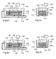
- Fig.6a-e illustrates the sequential steps of a presently preferred embodiment of the proposed method for treating wood.
- Fig.7a-e illustrates the same sequential steps as in the corresponding Fig.6a-e , but viewed from one of the short sides of the container 112.
- a container 112 is provided with an outlet 114 and an inlet 116, where the outlet 114 and the inlet 116 are interconnected by a conduit 118.
- the conduit in turn 118 is provided with a pump 120.
- Fig.6b and Fig.7b wood, in the form of boards 122 stacked in horizontal layers with board spacers 124 between each neighbouring pair of layers, is placed in the container 122.
- Fig.6c and Fig.7c four rod electrodes 126 are positioned vertically and distant from both the wood 122 and the walls of the container 112.
- a radio-frequency power-source 128 is provided.
- a specific volume of treatment liquid is provided in the container 112. The specific volume is sufficient for completely immersing the wood 122 and the electrodes 126 below the surface 130 of the treatment liquid.
- a first flow of the treatment liquid towards and from the wood 122 is provided by further activating the pump 120.
- the wood 122 is subjected to radio emission 132 from the electrodes 126 by activating the radio-frequency power-source 128.
Landscapes
- Life Sciences & Earth Sciences (AREA)
- Physics & Mathematics (AREA)
- Electromagnetism (AREA)
- Engineering & Computer Science (AREA)
- Wood Science & Technology (AREA)
- Forests & Forestry (AREA)
- Chemical And Physical Treatments For Wood And The Like (AREA)
Claims (23)
- Verfahren zur Holzbehandlung durch eine Behandlungsflüssigkeit umfassend die folgenden Schritte:Bereitstellen eines Behälters zum Aufbewahren des Holzes und der Behandlungsflüssigkeit,Unterbringen des Holzes im Behälter,Bereitstellen einer Elektrode im Behälter, um das Holz einer Funkemission zu unterwerfen,Bereitstellen eines spezifischen Volumens der Behandlungsflüssigkeit im Behälter, um zumindest teilweise das Holz zu bedecken, und um zumindest teilweise die Elektrode unter der Oberfläche der Behandlungsflüssigkeit zu bedecken,Unterwerfen des Holzes, das zumindest teilweise durch die Behandlungsflüssigkeit bedeckt ist, einer Exponierung durch Funkemission aus der Elektrode, um die Temperatur des Holzes zu erhöhen, gekennzeichnet durchBereitstellen einer ersten Strömung der Behandlungsflüssigkeit im Behälter zum sowie vom Holz, das zumindest teilweise durch die Behandlungsflüssigkeit bedeckt ist, durch Bereitstellen eines Auslasses für die Behandlungsflüssigkeit im Behälter, Bereitstellen eines Einlasses für die Behandlungsflüssigkeit im Behälter, und Verbinden des Auslasses und des Einlasses, um die Behandlungsflüssigkeit dazwischen zu leiten,Bereitstellen einer Umlaufströmung der Behandlungsflüssigkeit im Behälter durch den Auslass und über die Leitung zurück zum Behälter durch den Einlass, um zumindest etwas der Behandlungsflüssigkeit zu entfernen.
- Verfahren zur Holzbehandlung nach Anspruch 1, dadurch gekennzeichnet, dass der Auslass und/oder der Einlass eine einstellbare Position bezüglich des Behälters hat.
- Verfahren zur Holzbehandlung nach Anspruch 1 oder 2, dadurch gekennzeichnet, dass der Schritt des Bereitstellens einer ersten Strömung im Behälter ferner umfasst:Positionieren des Auslasses und des Einlasses an entgegengesetzten Seiten des Holzes.
- Verfahren zur Holzbehandlung nach Anspruch 1, 2 oder 3, dadurch gekennzeichnet, dass der Schritt des Bereitstellens einer ersten Strömung im Behälter ferner umfasst:Positionieren des Einlasses am Boden des Behälters.
- Verfahren zur Holzbehandlung nach einem der Ansprüche 1 bis 4, dadurch gekennzeichnet, dass es ferner den folgenden Schritt umfasst:Positionieren der Elektrode vom Holz entfernt, um es der ersten Strömung zu erlauben, zwischen dem Holz und der Elektrode zu passieren.
- Verfahren zur Holzbehandlung nach einem der Ansprüche 1 bis 5, dadurch gekennzeichnet, dass das Holz eine Vielzahl von Stücken von Holz umfasst, und das Verfahren ferner den folgenden Schritt umfasst:Positionieren der Stücke von Holz voneinander entfernt, um es der ersten Strömung zu erlauben, dazwischen zu passieren.
- Verfahren zur Holzbehandlung nach Anspruch 6, dadurch gekennzeichnet, dass die Stücke von Holz horizontal voneinander verlagert sind, um es der ersten Strömung zu erlauben, dazwischen vertikal zu passieren.
- Verfahren zur Holzbehandlung nach Anspruch 6 oder 7, dadurch gekennzeichnet, dass die Stücke von Holz vertikal voneinander verlagert sind, um es der ersten Strömung zu erlauben, dazwischen horizontal zu passieren.
- Verfahren zur Holzbehandlung nach einem der Ansprüche 1 bis 8, dadurch gekennzeichnet, dass es ferner die folgenden Schritte umfasst:Bereitstellen eines Wärmetauschers zum Kühlen der Behandlungsflüssigkeit im Behälter, undVerwenden des Wärmetauschers zum Entfernen von Wärme von der Behandlungsflüssigkeit im Behälter.
- Verfahren zur Holzbehandlung nach einem der Ansprüche 1 bis 9, dadurch gekennzeichnet, dass es ferner die folgenden Schritte umfasst:Bereitstellen eines Filters zum Entfernen von Partikeln, die aus dem Holz in die Behandlungsflüssigkeit ausgetrieben werden,Verwenden des Filters für die Behandlungsflüssigkeit im Behälter zum Entfernen zumindest einiger der Partikeln, die aus dem Holz ausgetrieben werden.
- Verfahren zur Holzbehandlung nach einem der Ansprüche 1 bis 10, dadurch gekennzeichnet, dass es ferner die folgenden Schritte umfasst:Bereitstellen eines Abscheiders zum Entfernen natürlicher Flüssigkeiten, die aus dem Holz in die Behandlungsflüssigkeit ausgetrieben werden, undVerwenden des Abscheiders für die Behandlungsflüssigkeit im Behälter zum Entfernen zumindest einiger der natürlichen Flüssigkeiten, die aus dem Holz ausgetrieben werden.
- Verfahren zur Holzbehandlung nach einem der Ansprüche 1 bis 11, dadurch gekennzeichnet, dass die Funkemission eine Frequenz im Bereich von ungefähr 10 MHz bis ungefähr 20 MHz hat.
- Verfahren zur Holzbehandlung nach einem der Ansprüche 1 bis 12, dadurch gekennzeichnet, dass die Behandlungsflüssigkeit am Holz eine Temperatur im Bereich von ungefähr 5 Grad C bis ungefähr 40 Grad C hat.
- Verfahren zur Holzbehandlung nach einem der Ansprüche 1 bis 13, dadurch gekennzeichnet, dass es ferner den folgenden Schritt umfasst:Aufteilen der Exponierung durch Funkemission in eine Vielzahl von aufeinanderfolgenden Exponierungen durch Funkemission aus der Elektrode, wobei die Vielzahl der aufeinanderfolgenden Exponierungen zeitlich getrennt ist, um die Temperatur des Holzes wiederholt zu erhöhen.
- Verfahren zur Holzbehandlung nach Anspruch 14, dadurch gekennzeichnet, dass es ferner den folgenden Schritt umfasst:Begrenzen der Zeit und Leistung jeder aufeinanderfolgenden Exponierung, um zu verhindern, dass die Temperatur des Holzes, das zumindest teilweise durch die Behandlungsflüssigkeit bedeckt ist, die Temperatur der Behandlungsflüssigkeit am Holz um höchstens ungefähr 50 Grad C übersteigt.
- Verfahren zur Holzbehandlung nach Anspruch 14 oder 15, dadurch gekennzeichnet, dass es ferner den folgenden Schritt umfasst:Bereitstellen einer Verzögerung zwischen einer ersten Exponierung und einer zweiten Exponierung der Vielzahl aufeinanderfolgender Exponierungen, wobei die zweite Exponierung auf die erste Exponierung folgt, und die Verzögerung es erlaubt, dass die Temperatur des Holzes, das zumindest teilweise durch die Behandlungsflüssigkeit bedeckt ist, unter eine Entspannungstemperatur nach der ersten Exponierung und vor der zweiten Exponierung gelangt, wobei die Entspannungstemperatur ungefähr 10 Grad über der Temperatur der Behandlungsflüssigkeit am Holz beträgt.
- Vorrichtung zur Holzbehandlung durch eine Behandlungsflüssigkeit umfassend:einen Behälter zum Aufbewahren des Holzes und der Behandlungsflüssigkeit, eine Elektrode, die zum Erwärmen des Holzes durch Ausstrahlen von Funkemission im Behälter positioniert ist, eine Hochfrequenz-Stromquelle zum Treiben der Elektrode, dadurch gekennzeichnet, dass sie ferner einen Strömungsgenerator umfasst zum Bereitstellen einer ersten Strömung der Behandlungsflüssigkeit zum sowie vom Holz, um zumindest etwas der Behandlungsflüssigkeit auszutauschen, wobei der Strömungsgenerator umfasst: einen Auslass zum Leiten der Behandlungsflüssigkeit vom Be-hälter, einen Einlass zum Leiten der Behandlungsflüssigkeit zum Behälter, eine Leitung, die den Auslass und den Einlass verbindet, und eine Pumpe zum Bereitstellen einer Umlaufströmung der Behandlungsflüssigkeit im Behälter durch den Auslass und über die Leitung zurück zum Behälter durch den Einlass.
- Vorrichtung nach Anspruch 17, dadurch gekennzeichnet, dass der Auslass und/oder der Einlass eine einstellbare Position bezüglich des Behälters hat.
- Vorrichtung nach Anspruch 17 oder 18, dadurch gekennzeichnet, dass der Auslass und der Einlass an entgegengesetzten Seiten des Holzes positioniert sind.
- Vorrichtung nach Anspruch 17, 18 oder 19, dadurch gekennzeichnet, dass sie ferner umfasst:einen Wärmetauscher zum Kühlen der Behandlungsflüssigkeit im Behälter.
- Vorrichtung nach einem der Ansprüche 17 bis 20, dadurch gekennzeichnet, dass sie ferner umfasst:einen Abscheider zum Entfernen von natürlichen Flüssigkeiten, die aus dem Holz in die Behandlungsflüssigkeit im Behälter ausgetrieben werden.
- Vorrichtung nach einem der Ansprüche 17 bis 21, dadurch gekennzeichnet, dass sie ferner umfasst:einen Filter zum Entfernen von Partikeln, die aus dem Holz in die Behandlungsflüssigkeit ausgetrieben werden.
- Vorrichtung zur Holzbehandlung nach einem der Ansprüche 17 bis 22, dadurch gekennzeichnet, dass die Hochfrequenz-Stromquelle ferner umfasst:eine Verzögerungsschaltung zum Bereitstellen einer Vielzahl von aufeinanderfolgenden Exponierungen des Holzes durch Funkemission aus der Elektrode, wobei die Vielzahl der aufeinanderfolgenden Exponierungen zeitlich getrennt ist, um die Temperatur des Holzes wiederholt zu erhöhen.
Applications Claiming Priority (1)
| Application Number | Priority Date | Filing Date | Title |
|---|---|---|---|
| PCT/IB2009/055224 WO2011061565A1 (en) | 2009-11-20 | 2009-11-20 | Process for treating wood |
Publications (2)
| Publication Number | Publication Date |
|---|---|
| EP2501528A1 EP2501528A1 (de) | 2012-09-26 |
| EP2501528B1 true EP2501528B1 (de) | 2013-10-16 |
Family
ID=42321156
Family Applications (1)
| Application Number | Title | Priority Date | Filing Date |
|---|---|---|---|
| EP09764094.0A Not-in-force EP2501528B1 (de) | 2009-11-20 | 2009-11-20 | Verfahren zur holzbehandlung |
Country Status (7)
| Country | Link |
|---|---|
| US (1) | US20120276302A1 (de) |
| EP (1) | EP2501528B1 (de) |
| JP (1) | JP2013511407A (de) |
| CN (1) | CN102712095A (de) |
| AU (1) | AU2009355500A1 (de) |
| CA (1) | CA2780086A1 (de) |
| WO (1) | WO2011061565A1 (de) |
Families Citing this family (12)
| Publication number | Priority date | Publication date | Assignee | Title |
|---|---|---|---|---|
| WO2010078413A1 (en) | 2008-12-31 | 2010-07-08 | Apinee, Inc. | Preservation of wood, compositions and methods thereof |
| US9878464B1 (en) | 2011-06-30 | 2018-01-30 | Apinee, Inc. | Preservation of cellulosic materials, compositions and methods thereof |
| RU2516259C2 (ru) * | 2011-11-21 | 2014-05-20 | Виктор Алексеевич Кухарев | Способ обработки древесных заготовок и устройство для его осуществления |
| DK178526B1 (en) * | 2015-03-05 | 2016-05-23 | Danish Wood Technology As | Method for Treatment of Wood |
| RU2595012C1 (ru) * | 2015-04-16 | 2016-08-20 | Елена Сергеевна Солодовникова | Способ обработки древесных материалов |
| JP2017045714A (ja) * | 2015-08-28 | 2017-03-02 | 東洋製罐グループホールディングス株式会社 | 高周波誘電加熱方法 |
| US20170181455A1 (en) * | 2015-12-23 | 2017-06-29 | Illinois Tool Works, Inc. | Apparatus and method for heating food products |
| CN106182250B (zh) * | 2016-07-13 | 2018-07-10 | 阜南县猛发工艺品有限公司 | 一种玉米秸秆的防霉改性处理方法 |
| CN107443524A (zh) * | 2017-07-04 | 2017-12-08 | 安徽信达家居有限公司 | 一种提高藤条加工性能的处理方法 |
| CN109500952A (zh) * | 2017-09-14 | 2019-03-22 | 贾海亮 | 一种竹制品漂白碳化一体装置 |
| CN113351603A (zh) * | 2021-07-09 | 2021-09-07 | 东莞南玻工程玻璃有限公司 | 镀膜玻璃批量除膜的方法 |
| CN114042596A (zh) * | 2021-10-21 | 2022-02-15 | 赵双龙 | 一种具有上料功能的地板生产加工用原料漂白装置 |
Family Cites Families (2)
| Publication number | Priority date | Publication date | Assignee | Title |
|---|---|---|---|---|
| EP1701775B2 (de) * | 2003-11-19 | 2012-06-13 | NATEX Prozesstechnologie GesmbH | Verfahren und prozess zur steuerung der temperatur-, druck- und dichteprofile in prozessen mit dichten fluiden und vorrichtung dafür |
| CN101918184B (zh) * | 2007-09-28 | 2015-01-14 | Gaia木专利股份公司 | 用于处理木材的方法 |
-
2009
- 2009-11-20 EP EP09764094.0A patent/EP2501528B1/de not_active Not-in-force
- 2009-11-20 WO PCT/IB2009/055224 patent/WO2011061565A1/en not_active Ceased
- 2009-11-20 JP JP2012539418A patent/JP2013511407A/ja active Pending
- 2009-11-20 CN CN2009801624989A patent/CN102712095A/zh active Pending
- 2009-11-20 AU AU2009355500A patent/AU2009355500A1/en not_active Abandoned
- 2009-11-20 CA CA2780086A patent/CA2780086A1/en not_active Abandoned
- 2009-11-20 US US13/508,833 patent/US20120276302A1/en not_active Abandoned
Also Published As
| Publication number | Publication date |
|---|---|
| US20120276302A1 (en) | 2012-11-01 |
| CA2780086A1 (en) | 2011-05-26 |
| CN102712095A (zh) | 2012-10-03 |
| EP2501528A1 (de) | 2012-09-26 |
| JP2013511407A (ja) | 2013-04-04 |
| AU2009355500A1 (en) | 2012-05-31 |
| WO2011061565A1 (en) | 2011-05-26 |
Similar Documents
| Publication | Publication Date | Title |
|---|---|---|
| US20120276302A1 (en) | Process for Treating Wood | |
| CA2700730C (en) | Process for treating wood by electromagnetic radiation through one or more electrodes | |
| EP3185648B1 (de) | Vorrichtung und verfahren zum erwärmen von lebensmittelprodukten | |
| CN107405784B (zh) | 木材的处理 | |
| Dehghannya et al. | Effect of ultrasound‐assisted osmotic dehydration pretreatment on drying kinetics and effective moisture diffusivity of mirabelle plum | |
| CN1326678C (zh) | 提高木材渗透性的方法 | |
| JP2004530585A (ja) | 木材の高周波処理方法 | |
| Resch | High-frequency electric current for drying of wood-historical perspectives | |
| FI77320B (fi) | Saett att torka traeprodukter. | |
| JP2021519232A (ja) | 木質材料の処理 | |
| JB Heffernan et al. | Joule heating of logs for phytosanitary purposes and timber processing pre-treatment | |
| Galyavetdinov et al. | IN THE PROCESS OF THERMO MODIFICATION OF WOOD IN LIQUIDS | |
| WO2019047724A1 (zh) | 一种浸入式加热循环器 | |
| RU2386912C1 (ru) | Способ сушки и пропитки древесины | |
| Smith et al. | Rapid fixation of CCA wood preservative with electromagnetic energy | |
| WO2007135222A1 (en) | Method for pressure impregnating wood or wood products with wood preservative containing vegetable oil and impregnated wood | |
| Kržišnik et al. | Preservative Retention and Penetration in Norway Spruce Wood as Influenced by Different Microwave Treatment Energy Levels | |
| CN210988061U (zh) | 一种农产品加工用高温蒸煮装置 | |
| BR112020018141B1 (pt) | Tratamento de materiais de madeira | |
| JPS6345664Y2 (de) | ||
| Jagadeesh | Application of shock waves in pencil manufacturing industry | |
| RU2318090C2 (ru) | Комбинированный способ снижения влажности грунта земляного полотна при строительстве дорог | |
| JPS62214952A (ja) | 樹脂含浸基材の製法 |
Legal Events
| Date | Code | Title | Description |
|---|---|---|---|
| PUAI | Public reference made under article 153(3) epc to a published international application that has entered the european phase |
Free format text: ORIGINAL CODE: 0009012 |
|
| 17P | Request for examination filed |
Effective date: 20120620 |
|
| AK | Designated contracting states |
Kind code of ref document: A1 Designated state(s): AT BE BG CH CY CZ DE DK EE ES FI FR GB GR HR HU IE IS IT LI LT LU LV MC MK MT NL NO PL PT RO SE SI SK SM TR |
|
| DAX | Request for extension of the european patent (deleted) | ||
| GRAP | Despatch of communication of intention to grant a patent |
Free format text: ORIGINAL CODE: EPIDOSNIGR1 |
|
| INTG | Intention to grant announced |
Effective date: 20130503 |
|
| GRAS | Grant fee paid |
Free format text: ORIGINAL CODE: EPIDOSNIGR3 |
|
| GRAA | (expected) grant |
Free format text: ORIGINAL CODE: 0009210 |
|
| AK | Designated contracting states |
Kind code of ref document: B1 Designated state(s): AT BE BG CH CY CZ DE DK EE ES FI FR GB GR HR HU IE IS IT LI LT LU LV MC MK MT NL NO PL PT RO SE SI SK SM TR |
|
| REG | Reference to a national code |
Ref country code: GB Ref legal event code: FG4D |
|
| REG | Reference to a national code |
Ref country code: CH Ref legal event code: EP |
|
| REG | Reference to a national code |
Ref country code: IE Ref legal event code: FG4D |
|
| REG | Reference to a national code |
Ref country code: AT Ref legal event code: REF Ref document number: 636238 Country of ref document: AT Kind code of ref document: T Effective date: 20131115 |
|
| REG | Reference to a national code |
Ref country code: DE Ref legal event code: R096 Ref document number: 602009019491 Country of ref document: DE Effective date: 20131212 |
|
| REG | Reference to a national code |
Ref country code: NL Ref legal event code: VDEP Effective date: 20131016 |
|
| REG | Reference to a national code |
Ref country code: AT Ref legal event code: MK05 Ref document number: 636238 Country of ref document: AT Kind code of ref document: T Effective date: 20131016 |
|
| REG | Reference to a national code |
Ref country code: LT Ref legal event code: MG4D |
|
| PG25 | Lapsed in a contracting state [announced via postgrant information from national office to epo] |
Ref country code: IS Free format text: LAPSE BECAUSE OF FAILURE TO SUBMIT A TRANSLATION OF THE DESCRIPTION OR TO PAY THE FEE WITHIN THE PRESCRIBED TIME-LIMIT Effective date: 20140216 Ref country code: FI Free format text: LAPSE BECAUSE OF FAILURE TO SUBMIT A TRANSLATION OF THE DESCRIPTION OR TO PAY THE FEE WITHIN THE PRESCRIBED TIME-LIMIT Effective date: 20131016 Ref country code: HR Free format text: LAPSE BECAUSE OF FAILURE TO SUBMIT A TRANSLATION OF THE DESCRIPTION OR TO PAY THE FEE WITHIN THE PRESCRIBED TIME-LIMIT Effective date: 20131016 Ref country code: NO Free format text: LAPSE BECAUSE OF FAILURE TO SUBMIT A TRANSLATION OF THE DESCRIPTION OR TO PAY THE FEE WITHIN THE PRESCRIBED TIME-LIMIT Effective date: 20140116 Ref country code: SE Free format text: LAPSE BECAUSE OF FAILURE TO SUBMIT A TRANSLATION OF THE DESCRIPTION OR TO PAY THE FEE WITHIN THE PRESCRIBED TIME-LIMIT Effective date: 20131016 Ref country code: BE Free format text: LAPSE BECAUSE OF FAILURE TO SUBMIT A TRANSLATION OF THE DESCRIPTION OR TO PAY THE FEE WITHIN THE PRESCRIBED TIME-LIMIT Effective date: 20131016 Ref country code: NL Free format text: LAPSE BECAUSE OF FAILURE TO SUBMIT A TRANSLATION OF THE DESCRIPTION OR TO PAY THE FEE WITHIN THE PRESCRIBED TIME-LIMIT Effective date: 20131016 Ref country code: LT Free format text: LAPSE BECAUSE OF FAILURE TO SUBMIT A TRANSLATION OF THE DESCRIPTION OR TO PAY THE FEE WITHIN THE PRESCRIBED TIME-LIMIT Effective date: 20131016 |
|
| PG25 | Lapsed in a contracting state [announced via postgrant information from national office to epo] |
Ref country code: AT Free format text: LAPSE BECAUSE OF FAILURE TO SUBMIT A TRANSLATION OF THE DESCRIPTION OR TO PAY THE FEE WITHIN THE PRESCRIBED TIME-LIMIT Effective date: 20131016 Ref country code: ES Free format text: LAPSE BECAUSE OF FAILURE TO SUBMIT A TRANSLATION OF THE DESCRIPTION OR TO PAY THE FEE WITHIN THE PRESCRIBED TIME-LIMIT Effective date: 20131016 Ref country code: LV Free format text: LAPSE BECAUSE OF FAILURE TO SUBMIT A TRANSLATION OF THE DESCRIPTION OR TO PAY THE FEE WITHIN THE PRESCRIBED TIME-LIMIT Effective date: 20131016 Ref country code: CY Free format text: LAPSE BECAUSE OF FAILURE TO SUBMIT A TRANSLATION OF THE DESCRIPTION OR TO PAY THE FEE WITHIN THE PRESCRIBED TIME-LIMIT Effective date: 20131016 |
|
| PG25 | Lapsed in a contracting state [announced via postgrant information from national office to epo] |
Ref country code: PT Free format text: LAPSE BECAUSE OF FAILURE TO SUBMIT A TRANSLATION OF THE DESCRIPTION OR TO PAY THE FEE WITHIN THE PRESCRIBED TIME-LIMIT Effective date: 20140217 |
|
| REG | Reference to a national code |
Ref country code: CH Ref legal event code: PL |
|
| PG25 | Lapsed in a contracting state [announced via postgrant information from national office to epo] |
Ref country code: LI Free format text: LAPSE BECAUSE OF NON-PAYMENT OF DUE FEES Effective date: 20131130 Ref country code: CH Free format text: LAPSE BECAUSE OF NON-PAYMENT OF DUE FEES Effective date: 20131130 Ref country code: EE Free format text: LAPSE BECAUSE OF FAILURE TO SUBMIT A TRANSLATION OF THE DESCRIPTION OR TO PAY THE FEE WITHIN THE PRESCRIBED TIME-LIMIT Effective date: 20131016 Ref country code: MC Free format text: LAPSE BECAUSE OF FAILURE TO SUBMIT A TRANSLATION OF THE DESCRIPTION OR TO PAY THE FEE WITHIN THE PRESCRIBED TIME-LIMIT Effective date: 20131016 |
|
| REG | Reference to a national code |
Ref country code: DE Ref legal event code: R119 Ref document number: 602009019491 Country of ref document: DE Effective date: 20140603 |
|
| PLBE | No opposition filed within time limit |
Free format text: ORIGINAL CODE: 0009261 |
|
| REG | Reference to a national code |
Ref country code: FR Ref legal event code: ST Effective date: 20140731 |
|
| STAA | Information on the status of an ep patent application or granted ep patent |
Free format text: STATUS: NO OPPOSITION FILED WITHIN TIME LIMIT |
|
| REG | Reference to a national code |
Ref country code: IE Ref legal event code: MM4A |
|
| PG25 | Lapsed in a contracting state [announced via postgrant information from national office to epo] |
Ref country code: CZ Free format text: LAPSE BECAUSE OF FAILURE TO SUBMIT A TRANSLATION OF THE DESCRIPTION OR TO PAY THE FEE WITHIN THE PRESCRIBED TIME-LIMIT Effective date: 20131016 Ref country code: IT Free format text: LAPSE BECAUSE OF FAILURE TO SUBMIT A TRANSLATION OF THE DESCRIPTION OR TO PAY THE FEE WITHIN THE PRESCRIBED TIME-LIMIT Effective date: 20131016 Ref country code: SK Free format text: LAPSE BECAUSE OF FAILURE TO SUBMIT A TRANSLATION OF THE DESCRIPTION OR TO PAY THE FEE WITHIN THE PRESCRIBED TIME-LIMIT Effective date: 20131016 Ref country code: DE Free format text: LAPSE BECAUSE OF NON-PAYMENT OF DUE FEES Effective date: 20140603 Ref country code: PL Free format text: LAPSE BECAUSE OF FAILURE TO SUBMIT A TRANSLATION OF THE DESCRIPTION OR TO PAY THE FEE WITHIN THE PRESCRIBED TIME-LIMIT Effective date: 20131016 Ref country code: RO Free format text: LAPSE BECAUSE OF FAILURE TO SUBMIT A TRANSLATION OF THE DESCRIPTION OR TO PAY THE FEE WITHIN THE PRESCRIBED TIME-LIMIT Effective date: 20131016 |
|
| 26N | No opposition filed |
Effective date: 20140717 |
|
| GBPC | Gb: european patent ceased through non-payment of renewal fee |
Effective date: 20140116 |
|
| PG25 | Lapsed in a contracting state [announced via postgrant information from national office to epo] |
Ref country code: DK Free format text: LAPSE BECAUSE OF FAILURE TO SUBMIT A TRANSLATION OF THE DESCRIPTION OR TO PAY THE FEE WITHIN THE PRESCRIBED TIME-LIMIT Effective date: 20131016 |
|
| PG25 | Lapsed in a contracting state [announced via postgrant information from national office to epo] |
Ref country code: IE Free format text: LAPSE BECAUSE OF NON-PAYMENT OF DUE FEES Effective date: 20131120 |
|
| PG25 | Lapsed in a contracting state [announced via postgrant information from national office to epo] |
Ref country code: GB Free format text: LAPSE BECAUSE OF NON-PAYMENT OF DUE FEES Effective date: 20140116 Ref country code: FR Free format text: LAPSE BECAUSE OF NON-PAYMENT OF DUE FEES Effective date: 20131216 |
|
| PG25 | Lapsed in a contracting state [announced via postgrant information from national office to epo] |
Ref country code: SI Free format text: LAPSE BECAUSE OF FAILURE TO SUBMIT A TRANSLATION OF THE DESCRIPTION OR TO PAY THE FEE WITHIN THE PRESCRIBED TIME-LIMIT Effective date: 20131016 |
|
| PG25 | Lapsed in a contracting state [announced via postgrant information from national office to epo] |
Ref country code: SM Free format text: LAPSE BECAUSE OF FAILURE TO SUBMIT A TRANSLATION OF THE DESCRIPTION OR TO PAY THE FEE WITHIN THE PRESCRIBED TIME-LIMIT Effective date: 20131016 |
|
| PG25 | Lapsed in a contracting state [announced via postgrant information from national office to epo] |
Ref country code: HU Free format text: LAPSE BECAUSE OF FAILURE TO SUBMIT A TRANSLATION OF THE DESCRIPTION OR TO PAY THE FEE WITHIN THE PRESCRIBED TIME-LIMIT; INVALID AB INITIO Effective date: 20091120 Ref country code: BG Free format text: LAPSE BECAUSE OF FAILURE TO SUBMIT A TRANSLATION OF THE DESCRIPTION OR TO PAY THE FEE WITHIN THE PRESCRIBED TIME-LIMIT Effective date: 20131016 Ref country code: MK Free format text: LAPSE BECAUSE OF FAILURE TO SUBMIT A TRANSLATION OF THE DESCRIPTION OR TO PAY THE FEE WITHIN THE PRESCRIBED TIME-LIMIT Effective date: 20131016 Ref country code: LU Free format text: LAPSE BECAUSE OF NON-PAYMENT OF DUE FEES Effective date: 20131120 |
|
| PG25 | Lapsed in a contracting state [announced via postgrant information from national office to epo] |
Ref country code: MT Free format text: LAPSE BECAUSE OF FAILURE TO SUBMIT A TRANSLATION OF THE DESCRIPTION OR TO PAY THE FEE WITHIN THE PRESCRIBED TIME-LIMIT Effective date: 20131016 Ref country code: GR Free format text: LAPSE BECAUSE OF NON-PAYMENT OF DUE FEES Effective date: 20131016 |
|
| PG25 | Lapsed in a contracting state [announced via postgrant information from national office to epo] |
Ref country code: GR Free format text: LAPSE BECAUSE OF FAILURE TO SUBMIT A TRANSLATION OF THE DESCRIPTION OR TO PAY THE FEE WITHIN THE PRESCRIBED TIME-LIMIT Effective date: 20140117 |
|
| PG25 | Lapsed in a contracting state [announced via postgrant information from national office to epo] |
Ref country code: TR Free format text: LAPSE BECAUSE OF FAILURE TO SUBMIT A TRANSLATION OF THE DESCRIPTION OR TO PAY THE FEE WITHIN THE PRESCRIBED TIME-LIMIT Effective date: 20131016 |