EP1700653A1 - Tour-Fraiseuse vertical - Google Patents
Tour-Fraiseuse vertical Download PDFInfo
- Publication number
- EP1700653A1 EP1700653A1 EP05005416A EP05005416A EP1700653A1 EP 1700653 A1 EP1700653 A1 EP 1700653A1 EP 05005416 A EP05005416 A EP 05005416A EP 05005416 A EP05005416 A EP 05005416A EP 1700653 A1 EP1700653 A1 EP 1700653A1
- Authority
- EP
- European Patent Office
- Prior art keywords
- shaft
- driving spindle
- cutter
- driving
- milling machine
- Prior art date
- Legal status (The legal status is an assumption and is not a legal conclusion. Google has not performed a legal analysis and makes no representation as to the accuracy of the status listed.)
- Withdrawn
Links
Images


Classifications
-
- B—PERFORMING OPERATIONS; TRANSPORTING
- B23—MACHINE TOOLS; METAL-WORKING NOT OTHERWISE PROVIDED FOR
- B23Q—DETAILS, COMPONENTS, OR ACCESSORIES FOR MACHINE TOOLS, e.g. ARRANGEMENTS FOR COPYING OR CONTROLLING; MACHINE TOOLS IN GENERAL CHARACTERISED BY THE CONSTRUCTION OF PARTICULAR DETAILS OR COMPONENTS; COMBINATIONS OR ASSOCIATIONS OF METAL-WORKING MACHINES, NOT DIRECTED TO A PARTICULAR RESULT
- B23Q1/00—Members which are comprised in the general build-up of a form of machine, particularly relatively large fixed members
- B23Q1/25—Movable or adjustable work or tool supports
- B23Q1/44—Movable or adjustable work or tool supports using particular mechanisms
- B23Q1/56—Movable or adjustable work or tool supports using particular mechanisms with sliding pairs only, the sliding pairs being the first two elements of the mechanism
- B23Q1/60—Movable or adjustable work or tool supports using particular mechanisms with sliding pairs only, the sliding pairs being the first two elements of the mechanism two sliding pairs only, the sliding pairs being the first two elements of the mechanism
- B23Q1/62—Movable or adjustable work or tool supports using particular mechanisms with sliding pairs only, the sliding pairs being the first two elements of the mechanism two sliding pairs only, the sliding pairs being the first two elements of the mechanism with perpendicular axes, e.g. cross-slides
- B23Q1/621—Movable or adjustable work or tool supports using particular mechanisms with sliding pairs only, the sliding pairs being the first two elements of the mechanism two sliding pairs only, the sliding pairs being the first two elements of the mechanism with perpendicular axes, e.g. cross-slides a single sliding pair followed perpendicularly by a single sliding pair
- B23Q1/626—Movable or adjustable work or tool supports using particular mechanisms with sliding pairs only, the sliding pairs being the first two elements of the mechanism two sliding pairs only, the sliding pairs being the first two elements of the mechanism with perpendicular axes, e.g. cross-slides a single sliding pair followed perpendicularly by a single sliding pair followed perpendicularly by a single sliding pair
-
- B—PERFORMING OPERATIONS; TRANSPORTING
- B23—MACHINE TOOLS; METAL-WORKING NOT OTHERWISE PROVIDED FOR
- B23B—TURNING; BORING
- B23B3/00—General-purpose turning-machines or devices, e.g. centre lathes with feed rod and lead screw; Sets of turning-machines
- B23B3/06—Turning-machines or devices characterised only by the special arrangement of constructional units
- B23B3/065—Arrangements for performing other machining operations, e.g. milling, drilling
-
- B—PERFORMING OPERATIONS; TRANSPORTING
- B23—MACHINE TOOLS; METAL-WORKING NOT OTHERWISE PROVIDED FOR
- B23Q—DETAILS, COMPONENTS, OR ACCESSORIES FOR MACHINE TOOLS, e.g. ARRANGEMENTS FOR COPYING OR CONTROLLING; MACHINE TOOLS IN GENERAL CHARACTERISED BY THE CONSTRUCTION OF PARTICULAR DETAILS OR COMPONENTS; COMBINATIONS OR ASSOCIATIONS OF METAL-WORKING MACHINES, NOT DIRECTED TO A PARTICULAR RESULT
- B23Q1/00—Members which are comprised in the general build-up of a form of machine, particularly relatively large fixed members
- B23Q1/25—Movable or adjustable work or tool supports
- B23Q1/64—Movable or adjustable work or tool supports characterised by the purpose of the movement
- B23Q1/66—Worktables interchangeably movable into operating positions
Definitions
- the present invention relates to a vertical compound lathe and milling machine for holding a working piece on a machining equipment and performing all machining operations such as cutting, milling, engraving, drilling, tapping, boring, grinding and the like that has a first driving spindle to hold cutters such as lathe cutters, milling cutters, engraving cutters, tapping cutters, boring cutters, drill gimlets, grinding cutters and is movable forward and backward, left and right, and up and down, and a second driving spindle and a working table located beneath the first driving spindle to hold the working piece such that all machining operations on the working piece can be finished through a single machining equipment to enhance fabrication efficiency and precision.
- a first driving spindle to hold cutters such as lathe cutters, milling cutters, engraving cutters, tapping cutters, boring cutters, drill gimlets, grinding cutters and is movable forward and backward, left and right, and up and down
- a second driving spindle and a working table located beneath the first driving
- the conventional metal fabrication machinery can be classified in single machines such as lathes, boring machines and the like, and compound machines such as milling machines, drilling machines and the like.
- the lathes and boring machines perform fabrication by rotating the working piece with the lathe cutter and boring cutter moving forwards linearly
- the milling machines and drilling machines perform fabrication by holding the working piece still with the milling cutter and drill gimlet held by the driving spindle to be rotated at a high speed and moved on the working piece.
- most present metal machinery are equipped with a cutter magazine and a cutter switching mechanism.
- the cutter held by the driving spindle may be switched with different types or dimensions of cutters in the cutter magazine through the switching mechanism and a preset control process.
- the milling cutters may be changed automatically to do machining operations such as milling, drilling, engraving, tapping, and grinding on the working piece.
- the lathe also can perform cutting and boring operations on the working piece by automatically switching the cutters.
- the conventional techniques available in industry heretofore still cannot provide compound functions of the lathe and the milling machine on an integrated machinery.
- a working piece often has to be moved to the lathe and milling machine to finish the compound machining operations they provide individually.
- the general practice in the industry is to procure one set of lathe and one set of milling machine in the plant.
- the working piece has to go through machining operation first on the lathe or milling machine, then is removed and mounted onto the milling machine or lathe to do other machining operations.
- a conventional fabrication machine 20 has a first driving spindle 24 for holding a cutter, and a first shaft 21 to move a second shaft 22 and a third shaft 23 up and down, the second shaft 22 to move the third shaft 23 left and right, and the third shaft 23 to move the driving spindle 24 forward and backward.
- the weight of the second shaft 22, third shaft 23 and driving spindle 24, and the driving force of the first driving spindle 24 applying on the working piece during machining operation are on the same side of the first shaft 21.
- the gravity center of the fabrication machine 20 tilts to one side during machining operation, and is not stable. Vibration and noise occur. The precision of the finished products often is not desirable. There is still room for improvement.
- the primary object of the present invention is to hold a working piece on a machine and finish machining operations such as cutting, milling, engraving, drilling, tapping, boring, grinding and the like without removing the working piece thereby to enhance machining efficiency and precision.
- Another object of the invention is to provide a sloped surface contact between a first shaft and a second shaft, and to provide a third shaft on the second shaft, a first driving spindle on the third shaft, and to divide the weight and driving force of the first driving spindle during machining operations to components of force in the vertical direction and horizontal direction so that the component of force in the horizontal direction on the first shaft is reduced to prevent tilting of the gravity center.
- the invention provides a number of features that include: a chassis is provided that has an indented holding space with a base on one side, the base holds a first shaft which is movable forwards and backwards, a second shaft mounted onto the first shaft that is movable left and right, a third shaft mounted onto the second shaft that is movable up and down, a first driving spindle mounted onto the third shaft that is turnable for a selected angle, the first driving spindle holds a machining cutter; the indented holding space holds a second driving spindle, a movable working table is provided between the second driving spindle and the first driving spindle, and the second driving spindle and the working table hold a working piece.
- FIGS. 1 through 6 for an embodiment of the vertical compound lathe and milling machine of the invention. It includes a chassis 50 which has a first shaft 60 located thereon movable forwards and backwards, and a platform 54 on one side at a higher elevation, and another side opposing the platform 54 at a lower elevation, and a holding space 51.
- the platform 54 has two first sliding tracks 541 and 542 that are spaced from each other and positioned in a forward and backward direction.
- the first screw bar 55 is driven by a first driving motor 551 to rotate in a positive direction or a reverse direction.
- the first screw bar 55 is coupled and engaged with a first screw sleeve 552 which is movable reciprocally forwards or backwards when the first screw bar 55 rotates in the positive direction or reverse direction.
- the first shaft 60 is located on the two first sliding tracks 541 and 542 to move forwards and backwards, and has a first sloped surface 65, and a bottom surface to couple with the first screw sleeve 552 to become one body and to be moved reciprocally forwards or backwards as the first screw bar 55 rotates in the positive or reverse direction.
- the first sloped surface 65 has two transverse and spaced second sliding tracks 61 and 62 that are interposed by a second screw bar 63.
- the second screw bar 63 is coupled and engaged with a second screw sleeve 632.
- the second screw bar 63 has one end driven by a second driving motor 631 to rotate in the positive or reverse direction.
- the second screw sleeve 632 is movable reciprocally leftwards and rightwards.
- the second shaft 70 has a second sloped surface 75.
- the second sloped surface 75 opposes and in parallel with the first sloped surface 65.
- One end of the second shaft 70 where the sloped surface is formed is coupled with the second screw sleeve 632 on the first sloped surface to become one body so that they are moved reciprocally leftwards or rightwards when the second screw bar 63 rotates in the positive or reverse direction.
- the second shaft 70 has a front end with two longitudinal and parallel and spaced third sliding tracks 71 and 72 located thereon.
- the third sliding tracks 71 and 72 hold a third shaft 80 which is movable up and down.
- the third shaft 80 is hollow and has the bottom end to couple with a first driving spindle 82, and houses a longitudinal third screw bar 81.
- the third screw bar 81 is driven by a third driving motor 811 located on the top end of the third shaft 80 to rotate in the positive or reverse direction.
- the third screw bar 81 is coupled and engaged with a third screw sleeve 812 which is fastened to one side between the third sliding tracks 71 and 72.
- the first driving spindle 82 can hold various cutters.
- the first driving spindle 82 By means of the first shaft 60, second shaft 70 and third shaft 80 that move forwards and backwards, leftwards and rightwards, and up and down, the first driving spindle 82 also is moved forwards and backwards, leftwards and rightwards, and up and down.
- a cutter magazine 76 on one side of the first shaft 60 that holds a plurality of cutters that may be turned and circulated, such as lathe cutters, milling cutters, drill gimlets, tapping cutters, boring cutters, grinding cutters, engraving cutters and the like (the cutter magazine is known in the art, thus details are omitted).
- the cutter switching mechanism 77 includes a fourth driving motor 771 and a switching cutter stem 772 which is driven by the fourth driving motor 771 and turnable for 180 degrees in one cycle. Each rotation is 180 degrees. During rotation, it switches the cutter on the first driving spindle 82 with a cutter held in the cutter magazine 76 so that the first driving spindle 82 can perform machining on the working piece.
- the holding space 51 of the chassis 50 aims to collect metal debris produced after machining.
- the holding space 51 has a plurality of anchor seats 511, 512, 513 and 514 that are extended upwards at the same elevation in a forward and backward manner opposing each other.
- the fourth sliding tracks 515 and 516 are parallel and extended to a rear side of the chassis 50.
- the holding space 51 and the platform 54 are joined on a longitudinal interface which has a rectangular opening 56 to allow the fourth sliding tracks 515 and 516 to pass through.
- the working table 90 is fastened to a cylinder rod 92 of an oil cylinder 91.
- the oil cylinder 91 is located close to the rear side of the chassis 50.
- the working table 90 may be driven by the oil cylinder 91 to move forwards and backwards.
- the holding space 51 further has a spindle seat 53 to hold a second driving spindle 57 which is driven by a fifth driving motor 52 to rotate.
- the working table 90 and the second driving spindle 57 aim to anchor the working piece.
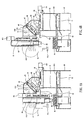
- the first driving spindle 40 has a coupling member 41 on the top end.
- the coupling member 41 has a rotary seat 42 on a lower side that may be driven to rotate.
- the rotary seat 42 has a holding space in the center with an opening leading downwards.
- the holding space holds a chuck 43 which is turnable when receiving a driving force.
- the rotation direction of the chuck 43 is vertical to the rotation direction of the rotary seat 42.
- the chuck 43 can hold various cutters. By means of the aforesaid structure, the cutters on the chuck 43 can perform machining on the working piece at different angles.
- the working table 90 holds and anchors a working piece 30 on the table top.
- the working piece 30 may be irregular in shape or have a large size.
- the first driving spindle 82 is moved forwards and backwards through the first shaft 60, leftwards and rightwards through the second shaft 70, and up and down through the third shaft 80.
- the cutter 25 held on the first driving spindle 82 can automatically perform machining operation on the working piece 30 on the working table 90 through the control of a computer process.
- the cutter 25 on the first driving spindle 82 may be switched with the cutters in the cutter magazine 76 through computer process control, so that the cutter 25 on the first driving spindle 82 can perform engraving, drilling, tapping, boring, grinding operation or the like on the working piece 30.
- the working piece is clamped by the second driving spindle 57.
- the working table 9 is moved in a space beneath the platform 54 by the oil cylinder 91. Due to the characteristics of the second driving spindle 57, it can hold only the working piece of a round shape or a smaller size.
- the cutter on the first driving spindle 82 may be switched with lathe or boring cutters in cutter magazine 76 through computer process control to do machining operations on the working piece 31 held by the second driving spindle 57.
- the operation angle of the first driving spindle 82 may be altered as shown in FIG. 9 to do machining on the working piece at varying angles without removing or remounting the working piece. Hence machining efficiency increases.
- the invention can provide the following advantages:
Landscapes
- Engineering & Computer Science (AREA)
- Mechanical Engineering (AREA)
- Machine Tool Units (AREA)
Priority Applications (1)
| Application Number | Priority Date | Filing Date | Title |
|---|---|---|---|
| EP05005416A EP1700653A1 (fr) | 2005-03-11 | 2005-03-11 | Tour-Fraiseuse vertical |
Applications Claiming Priority (1)
| Application Number | Priority Date | Filing Date | Title |
|---|---|---|---|
| EP05005416A EP1700653A1 (fr) | 2005-03-11 | 2005-03-11 | Tour-Fraiseuse vertical |
Publications (1)
| Publication Number | Publication Date |
|---|---|
| EP1700653A1 true EP1700653A1 (fr) | 2006-09-13 |
Family
ID=34934226
Family Applications (1)
| Application Number | Title | Priority Date | Filing Date |
|---|---|---|---|
| EP05005416A Withdrawn EP1700653A1 (fr) | 2005-03-11 | 2005-03-11 | Tour-Fraiseuse vertical |
Country Status (1)
| Country | Link |
|---|---|
| EP (1) | EP1700653A1 (fr) |
Cited By (29)
| Publication number | Priority date | Publication date | Assignee | Title |
|---|---|---|---|---|
| KR100916663B1 (ko) | 2009-06-01 | 2009-09-08 | (주)금호글로벌 | 장식용메달 엣지가공장치 |
| FR2928288A1 (fr) * | 2008-03-07 | 2009-09-11 | Sic Marking Holding Smh Soc Pa | Machine de marquage |
| CN102581624A (zh) * | 2012-03-14 | 2012-07-18 | 济南黑钻精密机床有限公司 | 一种定梁龙门式数控机床 |
| CN102896461A (zh) * | 2012-10-15 | 2013-01-30 | 江苏天宏自动化科技有限公司 | 五自由度机器人异形工件表面精整机 |
| RU2492967C1 (ru) * | 2012-04-26 | 2013-09-20 | Федеральное государственное бюджетное образовательное учреждение высшего профессионального образования "Российский университет дружбы народов" (РУДН) | Токарно-карусельный станок |
| CN103358225A (zh) * | 2012-04-06 | 2013-10-23 | 韶阳科技股份有限公司 | 一立轴二卧轴雕铣机 |
| CN103373807A (zh) * | 2012-04-11 | 2013-10-30 | 韶阳科技股份有限公司 | 一立轴二独立卧轴雕铣机 |
| CN103801940A (zh) * | 2012-11-06 | 2014-05-21 | 大连意美机械有限公司 | 一种数控机床 |
| CN103878535A (zh) * | 2012-12-19 | 2014-06-25 | 鸿准精密模具(昆山)有限公司 | 金属件加工方法 |
| CN103878534A (zh) * | 2012-12-19 | 2014-06-25 | 鸿准精密模具(昆山)有限公司 | 金属件加工方法 |
| CN103878588A (zh) * | 2012-12-19 | 2014-06-25 | 鸿准精密模具(昆山)有限公司 | 金属件加工方法 |
| CN104084847A (zh) * | 2014-06-23 | 2014-10-08 | 西安交通大学 | 一种龙门床身滚齿机的可交换双工作台与端面铣削的结构 |
| CN105252084A (zh) * | 2015-11-27 | 2016-01-20 | 重庆豪斯特汽车零部件有限公司 | 一种汽车头枕杆车床铣齿装置 |
| CN106217045A (zh) * | 2016-08-31 | 2016-12-14 | 天津金轮自行车集团有限公司 | 一种数控化钻孔装置 |
| CN106695335A (zh) * | 2015-07-23 | 2017-05-24 | 九仕恒自动化科技(昆山)有限公司 | 自动冲切雕铣一体机 |
| CN107738110A (zh) * | 2017-12-13 | 2018-02-27 | 沈阳机床(东莞)智能装备有限公司 | 一种氧化锆加工设备及四轴加工结构 |
| CN108555695A (zh) * | 2018-05-02 | 2018-09-21 | 中山市洪泉数控设备有限公司 | 一种双主轴车铣复合数控机床 |
| CN108608213A (zh) * | 2018-06-06 | 2018-10-02 | 杭州平成机械有限公司 | 一种用于制造太阳能光伏发电装置中下连接座的产线 |
| CN110449903A (zh) * | 2019-09-11 | 2019-11-15 | 广东汉明石阁机床有限公司 | 车铣复合机床 |
| CN113770410A (zh) * | 2021-09-08 | 2021-12-10 | 无锡鼎一重工制造有限公司 | 一种齿轮箱加工用可卧式镗孔和立式钻孔的转化装置 |
| CN113909816A (zh) * | 2021-10-18 | 2022-01-11 | 贵州天马虹山轴承有限公司 | 一种用于杆端关节轴承外圈的车铣复合加工方法 |
| CN114227264A (zh) * | 2021-12-25 | 2022-03-25 | 纽卡特行星减速机(沈阳)有限公司 | 一种基于多工位转换的机加工系统及电机锁紧环的加工工艺 |
| CN114346911A (zh) * | 2022-02-10 | 2022-04-15 | 宿州市勃普利尔自动化科技有限公司 | 一种基于机床加工打磨的主轴中心出水过滤系统 |
| CN114536016A (zh) * | 2022-03-24 | 2022-05-27 | 福建华韵竹木有限公司 | 菜板自动铣边及钻孔攻丝加工设备及其加工方法 |
| US11407071B2 (en) * | 2017-02-07 | 2022-08-09 | Makino Milling Machine Co., Ltd. | Machine tool |
| CN115365930A (zh) * | 2022-08-29 | 2022-11-22 | 廊坊市北方天宇机电技术有限公司 | 一种发动机罩盖打磨装置及方法 |
| CN116673798A (zh) * | 2023-05-16 | 2023-09-01 | 广东钜拓智能装备有限公司 | 一种精雕机 |
| CN117733656A (zh) * | 2024-02-20 | 2024-03-22 | 中国工程物理研究院材料研究所 | 一种高可靠性车铣复合加工中心 |
| WO2024060103A1 (fr) * | 2022-09-21 | 2024-03-28 | 中国科学院深圳先进技术研究院 | Machine-outil à commande numérique |
Citations (4)
| Publication number | Priority date | Publication date | Assignee | Title |
|---|---|---|---|---|
| US4583909A (en) * | 1982-05-12 | 1986-04-22 | Matsushita Electric Industrial Co., Ltd. | Industrial robot |
| US4632615A (en) * | 1984-02-09 | 1986-12-30 | Teijin Seiki Company Limited | Machine tools |
| US5117552A (en) * | 1990-04-20 | 1992-06-02 | Maho Aktiengesellschaft | Machining center |
| US5988959A (en) * | 1996-10-19 | 1999-11-23 | Horkos Corp. | Spindle supporting box structure, a damping structure, a gas supply related device, and a balance cylinder gas actuated device for machine tools |
-
2005
- 2005-03-11 EP EP05005416A patent/EP1700653A1/fr not_active Withdrawn
Patent Citations (4)
| Publication number | Priority date | Publication date | Assignee | Title |
|---|---|---|---|---|
| US4583909A (en) * | 1982-05-12 | 1986-04-22 | Matsushita Electric Industrial Co., Ltd. | Industrial robot |
| US4632615A (en) * | 1984-02-09 | 1986-12-30 | Teijin Seiki Company Limited | Machine tools |
| US5117552A (en) * | 1990-04-20 | 1992-06-02 | Maho Aktiengesellschaft | Machining center |
| US5988959A (en) * | 1996-10-19 | 1999-11-23 | Horkos Corp. | Spindle supporting box structure, a damping structure, a gas supply related device, and a balance cylinder gas actuated device for machine tools |
Cited By (38)
| Publication number | Priority date | Publication date | Assignee | Title |
|---|---|---|---|---|
| FR2928288A1 (fr) * | 2008-03-07 | 2009-09-11 | Sic Marking Holding Smh Soc Pa | Machine de marquage |
| WO2009115745A2 (fr) * | 2008-03-07 | 2009-09-24 | Sic Marking Holding - Smh | Machine de marquage |
| WO2009115745A3 (fr) * | 2008-03-07 | 2009-11-12 | Sic Marking Holding - Smh | Machine de marquage |
| KR100916663B1 (ko) | 2009-06-01 | 2009-09-08 | (주)금호글로벌 | 장식용메달 엣지가공장치 |
| CN102581624A (zh) * | 2012-03-14 | 2012-07-18 | 济南黑钻精密机床有限公司 | 一种定梁龙门式数控机床 |
| CN103358225A (zh) * | 2012-04-06 | 2013-10-23 | 韶阳科技股份有限公司 | 一立轴二卧轴雕铣机 |
| CN103373807A (zh) * | 2012-04-11 | 2013-10-30 | 韶阳科技股份有限公司 | 一立轴二独立卧轴雕铣机 |
| RU2492967C1 (ru) * | 2012-04-26 | 2013-09-20 | Федеральное государственное бюджетное образовательное учреждение высшего профессионального образования "Российский университет дружбы народов" (РУДН) | Токарно-карусельный станок |
| CN102896461A (zh) * | 2012-10-15 | 2013-01-30 | 江苏天宏自动化科技有限公司 | 五自由度机器人异形工件表面精整机 |
| CN103801940A (zh) * | 2012-11-06 | 2014-05-21 | 大连意美机械有限公司 | 一种数控机床 |
| CN103878535A (zh) * | 2012-12-19 | 2014-06-25 | 鸿准精密模具(昆山)有限公司 | 金属件加工方法 |
| CN103878534A (zh) * | 2012-12-19 | 2014-06-25 | 鸿准精密模具(昆山)有限公司 | 金属件加工方法 |
| CN103878588A (zh) * | 2012-12-19 | 2014-06-25 | 鸿准精密模具(昆山)有限公司 | 金属件加工方法 |
| CN103878534B (zh) * | 2012-12-19 | 2016-05-11 | 鸿准精密模具(昆山)有限公司 | 金属件加工方法 |
| CN103878535B (zh) * | 2012-12-19 | 2016-06-08 | 鸿准精密模具(昆山)有限公司 | 金属件加工方法 |
| CN103878588B (zh) * | 2012-12-19 | 2016-08-03 | 鸿准精密模具(昆山)有限公司 | 金属件加工方法 |
| CN104084847A (zh) * | 2014-06-23 | 2014-10-08 | 西安交通大学 | 一种龙门床身滚齿机的可交换双工作台与端面铣削的结构 |
| CN106695335A (zh) * | 2015-07-23 | 2017-05-24 | 九仕恒自动化科技(昆山)有限公司 | 自动冲切雕铣一体机 |
| CN105252084A (zh) * | 2015-11-27 | 2016-01-20 | 重庆豪斯特汽车零部件有限公司 | 一种汽车头枕杆车床铣齿装置 |
| CN106217045A (zh) * | 2016-08-31 | 2016-12-14 | 天津金轮自行车集团有限公司 | 一种数控化钻孔装置 |
| US11407071B2 (en) * | 2017-02-07 | 2022-08-09 | Makino Milling Machine Co., Ltd. | Machine tool |
| CN107738110A (zh) * | 2017-12-13 | 2018-02-27 | 沈阳机床(东莞)智能装备有限公司 | 一种氧化锆加工设备及四轴加工结构 |
| CN108555695A (zh) * | 2018-05-02 | 2018-09-21 | 中山市洪泉数控设备有限公司 | 一种双主轴车铣复合数控机床 |
| CN108608213A (zh) * | 2018-06-06 | 2018-10-02 | 杭州平成机械有限公司 | 一种用于制造太阳能光伏发电装置中下连接座的产线 |
| CN108608213B (zh) * | 2018-06-06 | 2024-02-13 | 杭州平成机械有限公司 | 一种用于制造太阳能光伏发电装置中下连接座的产线 |
| CN110449903A (zh) * | 2019-09-11 | 2019-11-15 | 广东汉明石阁机床有限公司 | 车铣复合机床 |
| CN113770410A (zh) * | 2021-09-08 | 2021-12-10 | 无锡鼎一重工制造有限公司 | 一种齿轮箱加工用可卧式镗孔和立式钻孔的转化装置 |
| CN113909816B (zh) * | 2021-10-18 | 2023-08-04 | 贵州天马虹山轴承有限公司 | 一种用于杆端关节轴承外圈的车铣复合加工方法 |
| CN113909816A (zh) * | 2021-10-18 | 2022-01-11 | 贵州天马虹山轴承有限公司 | 一种用于杆端关节轴承外圈的车铣复合加工方法 |
| CN114227264A (zh) * | 2021-12-25 | 2022-03-25 | 纽卡特行星减速机(沈阳)有限公司 | 一种基于多工位转换的机加工系统及电机锁紧环的加工工艺 |
| CN114346911A (zh) * | 2022-02-10 | 2022-04-15 | 宿州市勃普利尔自动化科技有限公司 | 一种基于机床加工打磨的主轴中心出水过滤系统 |
| CN114536016A (zh) * | 2022-03-24 | 2022-05-27 | 福建华韵竹木有限公司 | 菜板自动铣边及钻孔攻丝加工设备及其加工方法 |
| CN114536016B (zh) * | 2022-03-24 | 2023-09-08 | 福建华韵竹木有限公司 | 菜板自动铣边及钻孔攻丝加工设备及其加工方法 |
| CN115365930A (zh) * | 2022-08-29 | 2022-11-22 | 廊坊市北方天宇机电技术有限公司 | 一种发动机罩盖打磨装置及方法 |
| WO2024060103A1 (fr) * | 2022-09-21 | 2024-03-28 | 中国科学院深圳先进技术研究院 | Machine-outil à commande numérique |
| CN116673798A (zh) * | 2023-05-16 | 2023-09-01 | 广东钜拓智能装备有限公司 | 一种精雕机 |
| CN117733656A (zh) * | 2024-02-20 | 2024-03-22 | 中国工程物理研究院材料研究所 | 一种高可靠性车铣复合加工中心 |
| CN117733656B (zh) * | 2024-02-20 | 2024-05-07 | 中国工程物理研究院材料研究所 | 一种高可靠性车铣复合加工中心 |
Similar Documents
| Publication | Publication Date | Title |
|---|---|---|
| EP1700653A1 (fr) | Tour-Fraiseuse vertical | |
| US6796012B2 (en) | Milling machine for carrying out milling and turning operations on rod material | |
| US6904652B2 (en) | Universal machine tool | |
| US6457919B1 (en) | Multi-purpose machine tool for high volume secondary operations | |
| CN111673112A (zh) | 机械配件钻孔设备 | |
| EP0528052A1 (fr) | Machine-outil | |
| US4651404A (en) | Machine tool | |
| KR100768940B1 (ko) | 열교환기용 시트 플레이트 가공을 위한 드릴링 머신 | |
| CN109759620B (zh) | 连续加工的立式钻床 | |
| CN218136294U (zh) | 一种金属切削用组合机床 | |
| CN214212999U (zh) | 一种摇臂钻床的矩形工件限位装置 | |
| CN210703559U (zh) | 六轴镗铣加工机床 | |
| CN210651124U (zh) | 一种木工车铣复合机床 | |
| JP2506977B2 (ja) | 工作機 | |
| JP2001038502A (ja) | Nc旋盤 | |
| CN219684042U (zh) | 一种多轴钻床工作台的夹持组件 | |
| JP2001225235A (ja) | 工作機械 | |
| JP3476044B2 (ja) | 作業機械 | |
| CN213888308U (zh) | 一种方便清理的摇臂钻床 | |
| CN212917676U (zh) | 一种多孔加工装置 | |
| CN220128095U (zh) | 车铣一体机 | |
| KR101014306B1 (ko) | 탁상 드릴링 머신의 스핀들 지지장치 | |
| CN210648598U (zh) | 一种钻床 | |
| CN220094000U (zh) | 免编程铣磨钻攻镗一体机 | |
| CN218836908U (zh) | 一种用于阀球的粗车加工装置 |
Legal Events
| Date | Code | Title | Description |
|---|---|---|---|
| PUAI | Public reference made under article 153(3) epc to a published international application that has entered the european phase |
Free format text: ORIGINAL CODE: 0009012 |
|
| AK | Designated contracting states |
Kind code of ref document: A1 Designated state(s): AT BE BG CH CY CZ DE DK EE ES FI FR GB GR HU IE IS IT LI LT LU MC NL PL PT RO SE SI SK TR |
|
| AX | Request for extension of the european patent |
Extension state: AL BA HR LV MK YU |
|
| 17P | Request for examination filed |
Effective date: 20061221 |
|
| AKX | Designation fees paid |
Designated state(s): AT BE BG CH CY CZ DE DK EE ES FI FR GB GR HU IE IS IT LI LT LU MC NL PL PT RO SE SI SK TR |
|
| STAA | Information on the status of an ep patent application or granted ep patent |
Free format text: STATUS: THE APPLICATION IS DEEMED TO BE WITHDRAWN |
|
| 18D | Application deemed to be withdrawn |
Effective date: 20091001 |