EP1698513A1 - Wechselbehälter mit eingebautem Leiter zur Aufnahme und zum Transport von Materialien - Google Patents
Wechselbehälter mit eingebautem Leiter zur Aufnahme und zum Transport von Materialien Download PDFInfo
- Publication number
- EP1698513A1 EP1698513A1 EP06290368A EP06290368A EP1698513A1 EP 1698513 A1 EP1698513 A1 EP 1698513A1 EP 06290368 A EP06290368 A EP 06290368A EP 06290368 A EP06290368 A EP 06290368A EP 1698513 A1 EP1698513 A1 EP 1698513A1
- Authority
- EP
- European Patent Office
- Prior art keywords
- bucket
- wall
- side walls
- walls
- doors
- Prior art date
- Legal status (The legal status is an assumption and is not a legal conclusion. Google has not performed a legal analysis and makes no representation as to the accuracy of the status listed.)
- Granted
Links
Images


Classifications
-
- B—PERFORMING OPERATIONS; TRANSPORTING
- B65—CONVEYING; PACKING; STORING; HANDLING THIN OR FILAMENTARY MATERIAL
- B65D—CONTAINERS FOR STORAGE OR TRANSPORT OF ARTICLES OR MATERIALS, e.g. BAGS, BARRELS, BOTTLES, BOXES, CANS, CARTONS, CRATES, DRUMS, JARS, TANKS, HOPPERS, FORWARDING CONTAINERS; ACCESSORIES, CLOSURES, OR FITTINGS THEREFOR; PACKAGING ELEMENTS; PACKAGES
- B65D90/00—Component parts, details or accessories for large containers
- B65D90/008—Doors for containers, e.g. ISO-containers
-
- B—PERFORMING OPERATIONS; TRANSPORTING
- B60—VEHICLES IN GENERAL
- B60P—VEHICLES ADAPTED FOR LOAD TRANSPORTATION OR TO TRANSPORT, TO CARRY, OR TO COMPRISE SPECIAL LOADS OR OBJECTS
- B60P1/00—Vehicles predominantly for transporting loads and modified to facilitate loading, consolidating the load, or unloading
- B60P1/04—Vehicles predominantly for transporting loads and modified to facilitate loading, consolidating the load, or unloading with a tipping movement of load-transporting element
- B60P1/28—Tipping body constructions
- B60P1/283—Elements of tipping devices
- B60P1/286—Loading buckets
-
- B—PERFORMING OPERATIONS; TRANSPORTING
- B65—CONVEYING; PACKING; STORING; HANDLING THIN OR FILAMENTARY MATERIAL
- B65D—CONTAINERS FOR STORAGE OR TRANSPORT OF ARTICLES OR MATERIALS, e.g. BAGS, BARRELS, BOTTLES, BOXES, CANS, CARTONS, CRATES, DRUMS, JARS, TANKS, HOPPERS, FORWARDING CONTAINERS; ACCESSORIES, CLOSURES, OR FITTINGS THEREFOR; PACKAGING ELEMENTS; PACKAGES
- B65D88/00—Large containers
- B65D88/02—Large containers rigid
- B65D88/12—Large containers rigid specially adapted for transport
- B65D88/122—Large containers rigid specially adapted for transport with access from above
- B65D88/123—Large containers rigid specially adapted for transport with access from above open top
-
- B—PERFORMING OPERATIONS; TRANSPORTING
- B65—CONVEYING; PACKING; STORING; HANDLING THIN OR FILAMENTARY MATERIAL
- B65D—CONTAINERS FOR STORAGE OR TRANSPORT OF ARTICLES OR MATERIALS, e.g. BAGS, BARRELS, BOTTLES, BOXES, CANS, CARTONS, CRATES, DRUMS, JARS, TANKS, HOPPERS, FORWARDING CONTAINERS; ACCESSORIES, CLOSURES, OR FITTINGS THEREFOR; PACKAGING ELEMENTS; PACKAGES
- B65D90/00—Component parts, details or accessories for large containers
- B65D90/0033—Lifting means forming part of the container
-
- B—PERFORMING OPERATIONS; TRANSPORTING
- B65—CONVEYING; PACKING; STORING; HANDLING THIN OR FILAMENTARY MATERIAL
- B65D—CONTAINERS FOR STORAGE OR TRANSPORT OF ARTICLES OR MATERIALS, e.g. BAGS, BARRELS, BOTTLES, BOXES, CANS, CARTONS, CRATES, DRUMS, JARS, TANKS, HOPPERS, FORWARDING CONTAINERS; ACCESSORIES, CLOSURES, OR FITTINGS THEREFOR; PACKAGING ELEMENTS; PACKAGES
- B65D2590/00—Component parts, details or accessories for large containers
- B65D2590/0091—Ladders
-
- B—PERFORMING OPERATIONS; TRANSPORTING
- B65—CONVEYING; PACKING; STORING; HANDLING THIN OR FILAMENTARY MATERIAL
- B65D—CONTAINERS FOR STORAGE OR TRANSPORT OF ARTICLES OR MATERIALS, e.g. BAGS, BARRELS, BOTTLES, BOXES, CANS, CARTONS, CRATES, DRUMS, JARS, TANKS, HOPPERS, FORWARDING CONTAINERS; ACCESSORIES, CLOSURES, OR FITTINGS THEREFOR; PACKAGING ELEMENTS; PACKAGES
- B65D90/00—Component parts, details or accessories for large containers
- B65D90/12—Supports
- B65D90/18—Castors, rolls, or the like; e.g. detachable
Definitions
- the present invention relates to a bucket, preferably removable, for storing and transporting material and / or materials, of the type comprising a box defined by means of side walls and a bottom, this box being closed at one end by a front wall front.
- a removable bucket whose design makes it possible to increase the useful width of the bucket, to facilitate the maintenance and the replacement of its outer faces, which can be used in particular as a display surface, has been described in application FR 2,871,419 of the same applicant.
- the side walls of said bucket have reinforcements extending in the longitudinal direction and / or transverse walls of the bucket, these reinforcements being profiled to be secured to the inner faces of the walls of the bucket so as to form stiffening boxes leaving totally free the outer faces of the side walls capable of constituting, in particular, display surfaces.
- the outer faces of the side walls remain free and smooth and can thus constitute in particular display surfaces.
- the arrangement of the reinforcing elements inside the bucket of general parallelepiped shape makes it possible to increase the useful width of this bucket and consequently the useful volume of said bucket.
- a first important development is the use of a ladder.
- the personnel in charge of transporting these dumpsters must, before moving them, cover their upper part with a protective net, or a removable cover to prevent the fall or flight, out of the bucket, of materials contained in the latter.
- the height of the buckets generally exceeding 2 meters, the staff therefore needs a ladder to set up and fix the net or removable cover in the upper part of the bucket. If this ladder is portable, they must move it many times around the bucket, to access the different points of attachment of the net, with many risks of lateral sliding of the top of the ladder, supported on the smooth walls of the dumpster.
- modules consisting of a cavity in the form of a half-cylinder in the axis of which is disposed a horizontal bar. These modules adapt to a succession of openings cut in the walls of structures (truck, plane ...) that they thus close, and constitute the degrees of a scale. Fixing these modules, however, requires the bolting of a collar, or a peripheral weld.
- a first object of the invention is therefore to provide a bucket comprising a ladder not having the aforementioned drawbacks, and in particular that does not protrude beyond the outer faces of the side walls of said bucket, while simplifying its manufacture.
- a second essential arrangement concerns, in addition to the closure system, the presence of a safety locking system of the rear doors of the bucket.
- a safety locking system of the rear doors of the bucket Conventionally, it consists of a cremone closure device associated with a latch, and a door locking device comprising door locking hooks, operable at means of a handle, disposed on the longitudinal side of the bucket, projecting from the side wall.
- the staff must come to the back of the bucket to drive the cremone on the move. Frequent accidents occur when the user actuates the espagnolette while the locking hooks are not in the locked position. If the bucket is full, the load may spill onto the operator.
- Another object of the invention is therefore to provide a bucket comprising a simple system for closing and locking doors which overcomes the aforementioned drawbacks, while facilitating emptying operations of the bucket, and which does not protrude beyond outer faces of the side walls of said bucket while releasing the surfaces of the rear doors.
- a third arrangement relates to the legs of the gripping ring of the bucket on the front face.
- a removable bucket is often used as a receptacle for materials, usually placed on the ground. This receptacle is intended to be loaded on a truck for transport.
- the bucket has, on its front face, a gripping ring, associated with reinforcements called jambs extending down to the longitudinal lower rails disposed under the body of the bucket.
- Another necessary arrangement relates to a device for holding the rear doors of the bucket in the open position. Indeed, when unloading the bucket for example, the doors are folded against the outer face of the side walls of the bucket and must be held in place in this position during the entire operation.
- the conventional bucket holding devices are housed on or between the outer reinforcements of the side walls. In the present case, it is out of the question to place on the buckets according to the invention, retaining hooks protruding on the outer surface of the side walls which must remain free, flat and smooth.
- the present invention therefore aims to overcome the aforementioned drawbacks and to propose arrangements and / or accessories adapted to the type of bucket as described in the application FR 2 871 419, which allow to keep its outer walls free, flat and smooth.
- the present invention relates to a bucket, preferably removable, for the storage and transport of material and / or materials, of the type comprising a box defined by side walls and a bottom, and closed at one end by a front end wall, the side walls of the bucket having reinforcements extending in the longitudinal direction and / or transverse walls of the bucket, these reinforcements being profiled to be secured to the inner faces of the walls of the bucket so as to form stiffening boxes leaving completely free the external faces of the side walls suitable for constituting, in particular, display surfaces, characterized in that at least one ladder is formed in the plane, or away from the outer plane of at least one wall of the bucket, said ladder being formed of a succession of vertically aligned openings, preferably regularly spaced and arranged in at least a wall of the bucket, vis-à-vis one or more recessed areas of a profiled vertical reinforcement secured to the inner face of said wall.
- the reinforcements inside the bucket in the form of inserts and the positioning of the ladder in the plane or in withdrawal of the external faces of the side walls, the latter remain free and smooth and can thus constitute in particular display surfaces.
- the arrangement of the reinforcing elements inside the bucket of general parallelepiped shape makes it possible to increase the useful width of this bucket and consequently the useful volume of said bucket.
- the user of the bucket has integrated degrees including access to the upper part of the bucket and therefore for example, put in place, for example the protective nets loading said bucket.
- the reinforcement is an open hollow section, section having the approximate shape of a C or a U whose ends of the branches are secured to the inner face of the wall. Thanks to this configuration of the profile, it prevents spillage of the content of the bucket through said openings.
- the presence of these pre-existing profiles as reinforcements is used to simplify the scale.
- the bucket 1, object of the invention is intended for the transport and / or storage of equipment and / or materials.
- This bucket can be removably positioned on the chassis of a transport vehicle or be permanently attached to the chassis of the vehicle.
- This bucket can still rest in support of the ground and be a material storage bucket or, covered in the upper part, serve as a safe for storing equipment, for example on a construction site.
- this bin parallelepiped general shape is formed of a box delimited by means of at least side walls 2 and a bottom 3.
- the side walls 2 and the bottom 3 are made from panels or sheets sheet metal generally welded together to form said walls.
- the side walls 2 and the bottom 3 thus delimit a box of parallelepiped general appearance closed at one end by a front wall 4 and at its other end by rear doors 5.
- the bucket 1 according to the invention is generally open at the top, but may, if necessary, be equipped with an upper wall.
- the side walls 2 of the bucket have reinforcements 6, 8 extending in the longitudinal direction and / or transverse walls 2 of the bucket.
- These reinforcements 6, 8 are profiled to be secured to the inner faces of the walls 2 of the bucket to form stiffening boxes leaving completely free the outer faces of the side walls.
- These external faces are thus able to constitute, in particular, display surfaces. They may be coated with a finishing paint or an adhesive film, for example vinyl type. Due to the flatness of these outer walls, their maintenance is facilitated as well as their replacement in case of premature wear.
- the shape of the longitudinal or transverse reinforcements 8 may be as described in the patent application FR 2 871 419, in particular with sloped top faces inclined towards the inside of the bucket or chamfered faces, so as to facilitate the flow of materials, especially when unloading the bucket 1.
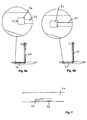
- a ladder formed of a succession of vertically aligned openings 10, preferably regularly spaced. These openings 10 are formed in at least one wall of the bucket 1, vis-à-vis one or more areas 11 hollow a transverse reinforcement, here vertical 8 profiled secured to the inner face of said wall.
- this succession of openings 10 forms a ladder formed in the plane or withdrawn from the outer plane of this wall, and therefore "integrated" with the bucket 1.
- This scale being integrated into said bucket 1, it can not be forgotten or lost nor deformed; the risks of sliding along the walls are also completely eliminated.
- the vertical reinforcement 8 is a hollow profile, open along one of its generatrices, the opening of the profile being turned towards the wall of the bucket 1.
- the section of this section has the approximate shape of a C or a U whose ends of the branches are secured to the inner face of the wall of the bucket 1.
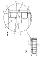
- the panel or sheet metal sheet 12 constituting the wall 2 or the front side 4 of the bucket is cut at at least one of its lateral ends, vertically crenellated, forming a succession of openings 10, separated by horizontal elements 13 constituting the degrees of said scale .
- the openings 10 are located opposite the corresponding hollow portion (s) 11 of the vertical upright 8 welded to the rear face of the panel or sheet metal sheet 12.
- the horizontal elements 13, preferably regularly spaced, are fixed at the lateral end of the panel or sheet metal sheet 12, in the plan of it (or withdrawn from this plane), so as to constitute the degrees of said scale.
- the profiled vertical upright 8 also has a section in approximate shape of a C, one of whose branches is secured to the inner edge of the panel 12, and the other branch is secured to the terminations of the horizontal elements 13
- the profiled amount 8 exceeds several centimeters of the panel 12 and thus increases the length of the wall and therefore the total useful volume of the bucket 1.
- openings serving as degrees for going up or down have a lower edge covered with a protection 14; it is preferably openings located in the upper half of the height of the bucket, so as to prevent injury of the user's hands on these cutting edges.
- integrated ladders according to the invention may be formed in the side or front walls 4 facing each of the vertical reinforcements 8 located at the four corners of the skip 1.
- This espagnolette 25 consists of at least one rotating rod driven in angular displacement via the operating handle forming with the rod a bracket, this rod disposed in the thickness of one of the door panels being provided with one of its ends said upper of a locking hook (not shown) for cooperating with a slot in the other door and at its other end, said lower, by a bolt for cooperating with a striker arranged on the front part of the bucket against which the handle is applied.
- the espagnolette 25 is operated using an operating handle 22 extending under the doors 5.
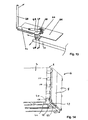
- This handle passes from a position under a first door to a position under the second door during the opening operations or respectively closing the doors, this handle having the shape of an arm 22 whose end is, according to the present invention, immobilized in the closed position by a locking device sliding on said end and manually operable by an operator placed along the one of the side walls 2 of the body of the bucket 1 or automatically operable during the emptying of the bucket.
- the closing and locking device comprises a lever 23 passing through lights arranged in alignment in the lower crosspieces 30, 31 disposed under the bottom of the bucket, one end of said lever 23 being provided with an annular portion 24 sliding on the end of the arm 22 forming the operating handle of the cremone, to ensure its locking.
- this locking device allows both to keep the doors 5 closed and a safety lock thereof.
- the lever 23 is a pivoting lever, with a vertical axis 28, which is also axially movable when the locked position is moved to the unlocked position and Conversely.
- the light 26, shown in Figure 7, distal from the annular portion 24 has a vertical recess 27 for receiving the lever 23 in the locking position of the arm 22 forming the operating handle of the espagnolette 25.
- the vertical axis 28 around which the lever 23 pivots is advantageously housed in an oblong-shaped orifice formed either in the support 33 of the locking device (see FIGS. 8a and 8b) or in the lever 23 itself. which allows the axis to move a few millimeters in the case of a violent shock towards the back of the bucket on the handle of the espagnolette.
- the arm 22 can thus move backwards which protects it from any deformation or torsion during the impact.
- the closure and locking device of the arm 22 is located in a rear left corner of the bucket, under the bottom of this bucket, so as to be easily accessible and manually operable by an operator placed along of one of the side walls 2.
- the closing and locking device of the arm 22 can comprise a handle 40 accessible through one of the openings 10 formed in a lateral wall 2 of the bucket 1 facing a reinforcement, such as a vertical reinforcement 8 disposed in the vicinity of an angle of the bucket.
- the control member 41 has the shape of a pivoting lever that has one of its branches forming a handle 40, here vertical, accessible through an opening 10 while the another branch, shown at 49 in this figure 13, is pivotally coupled to a plate 44 extending under the bottom of the bucket 1.
- This branch 49 acts, during the angular displacement of the lever pivotally mounted around a axis 45, on the locking member 48 which releases the end 47 of the arm 22 of operation of the espagnolette.
- the control member 41 is further loaded by a spring 43 which extends between the plate 44 and the control member 41. This spring recalls the control member 41 in a locked position of the doors. The pivotal movement of this member 41 operates against the action of the spring which recalls the body 41 of control in a limited position by a limit stop 46 carried by the plate 44.
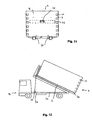
- the closure and locking device can be automatically actuated during emptying of the bucket.
- it is for example connected to a cable 36 passing under the bottom 3 of the bucket to the front of the bucket and fixed non-permanently to the chassis 34 of the vehicle 35.
- This cable 36 may, for example, be fixed to the frame 34 by means of a magnet 37, which can be detached from said frame 34, for a certain predefined tilt of the bucket.
- the front wall 4 of the box of the bucket comprises a gripping ring 40 connected to a reinforcement disposed on the inner wall, without a leg between said ring and the cradles 38 of the bucket, so as to increase the display surfaces of this front wall.
- the gripping ring is integral for example with a reinforcing beam 32 (shown in dotted lines) preferably disposed horizontally on the internal face of the front wall 4, thus leaving the outer face free.
- a notch 39 formed in a strip 29 extending around the face forming the bottom of the bucket 1 serves as a hooking means for keeping the two rear doors 5 in the open position in the folded state against the walls 2 side of the bucket without the attachment means does not exceed the total width of his bucket.
- a notch is adapted to receive for example the rings of a short chain secured to the lower edge of said door 5, when it is folded against an external lateral face 2 of the bucket. All the arrangements described in this application are integrated into the bucket, allowing it to not exceed the total width currently allowed, and thus optimizing its useful volume.
Applications Claiming Priority (1)
| Application Number | Priority Date | Filing Date | Title |
|---|---|---|---|
| FR0502225A FR2882735A1 (fr) | 2005-03-04 | 2005-03-04 | Benne amovible a echelles integrees pour le stockage et le transport de materiaux |
Publications (2)
| Publication Number | Publication Date |
|---|---|
| EP1698513A1 true EP1698513A1 (de) | 2006-09-06 |
| EP1698513B1 EP1698513B1 (de) | 2007-10-24 |
Family
ID=35124549
Family Applications (1)
| Application Number | Title | Priority Date | Filing Date |
|---|---|---|---|
| EP06290368A Not-in-force EP1698513B1 (de) | 2005-03-04 | 2006-03-03 | Wechselbehälter mit eingebautem Leiter zur Aufnahme und zum Transport von Materialien |
Country Status (4)
| Country | Link |
|---|---|
| EP (1) | EP1698513B1 (de) |
| AT (1) | ATE376501T1 (de) |
| DE (1) | DE602006000177D1 (de) |
| FR (1) | FR2882735A1 (de) |
Cited By (5)
| Publication number | Priority date | Publication date | Assignee | Title |
|---|---|---|---|---|
| FR2924996A1 (fr) * | 2007-12-14 | 2009-06-19 | H D P S Soc Par Actions Simpli | Benne, de preference amovible, pour le stockage et le transport de charge |
| JP2013103736A (ja) * | 2011-11-14 | 2013-05-30 | Toa Jidosha Kogyo Kk | 組立式コンテナ及び組立式コンテナの輸送方法 |
| FR3012435A1 (fr) * | 2013-10-24 | 2015-05-01 | Porta | Containers polybennes routiers compatibles containers maritimes chargeables sur train ou porteurs routiers |
| CN108128228A (zh) * | 2017-12-21 | 2018-06-08 | 北奔重型汽车集团有限公司 | 一种自卸车货箱内腔结构 |
| CN108454492A (zh) * | 2017-02-21 | 2018-08-28 | 中集车辆(集团)有限公司 | 自卸半挂车及其车厢 |
Families Citing this family (3)
| Publication number | Priority date | Publication date | Assignee | Title |
|---|---|---|---|---|
| DE102011105365B4 (de) | 2011-06-22 | 2014-03-20 | GPI Ges. f. Prüfstanduntersuchungen und Ingenieurdienstleistungen mbH | Behältereinheit |
| DE102012009047B4 (de) | 2012-05-04 | 2021-08-19 | Rewald Gmbh | Einrichtung zum Verriegeln von an Containerseitenwänden schwenkbar gelagerten Türflügeln für aufnehmbare Container |
| FR3074113B1 (fr) * | 2017-11-29 | 2019-11-22 | Societe De Carrosserie Industrielle,Socari | Benne a paroi laterale basculante |
Citations (12)
| Publication number | Priority date | Publication date | Assignee | Title |
|---|---|---|---|---|
| US1617809A (en) * | 1925-12-07 | 1927-02-15 | Harry S Hart | Hopper-car end and ladder construction |
| US1714451A (en) * | 1926-06-10 | 1929-05-21 | Royal Railway Improvements Cor | Ladder |
| GB1315073A (en) * | 1970-08-24 | 1973-04-26 | Fruehauf Corp | Combination of a tank and supporting framework therefor |
| US3971456A (en) | 1975-04-10 | 1976-07-27 | Yonce Everett R | Handle-rung module |
| FR2485492A1 (fr) * | 1980-06-30 | 1981-12-31 | Alusuisse | Conteneur pour le transport de marchandises |
| EP0438361A1 (de) * | 1990-01-19 | 1991-07-24 | S.E.S.R. - Societe Europeenne De Semi-Remorques | Kipperaufbau mit einer Sicherheitsverriegelungsvorrichtung |
| DE9203198U1 (de) * | 1992-03-10 | 1993-08-05 | Maschinenfabriken Bernard Krone Gmbh, 48480 Spelle, De | |
| FR2710591A1 (fr) | 1993-10-01 | 1995-04-07 | Fabrication Cie Ind | Benne basculante et notamment camion à benne basculante. |
| DE19922512C1 (de) * | 1999-05-15 | 2000-11-23 | Schmitz Cargobull Ag | Rückwand für ein Lastfahrzeug |
| US20020053814A1 (en) * | 2000-11-08 | 2002-05-09 | Vantage Dump Trailers, Inc. | Tapered trailer with horizontal seams and support rails |
| DE20218845U1 (de) * | 2002-12-05 | 2003-02-13 | Mkg Metall Und Kunststoffverar | Laderaumtür |
| FR2871419A1 (fr) | 2004-06-11 | 2005-12-16 | Christian Moreau | Benne de transport et/ou de stockage des materiaux |
-
2005
- 2005-03-04 FR FR0502225A patent/FR2882735A1/fr not_active Withdrawn
-
2006
- 2006-03-03 DE DE602006000177T patent/DE602006000177D1/de active Active
- 2006-03-03 EP EP06290368A patent/EP1698513B1/de not_active Not-in-force
- 2006-03-03 AT AT06290368T patent/ATE376501T1/de not_active IP Right Cessation
Patent Citations (12)
| Publication number | Priority date | Publication date | Assignee | Title |
|---|---|---|---|---|
| US1617809A (en) * | 1925-12-07 | 1927-02-15 | Harry S Hart | Hopper-car end and ladder construction |
| US1714451A (en) * | 1926-06-10 | 1929-05-21 | Royal Railway Improvements Cor | Ladder |
| GB1315073A (en) * | 1970-08-24 | 1973-04-26 | Fruehauf Corp | Combination of a tank and supporting framework therefor |
| US3971456A (en) | 1975-04-10 | 1976-07-27 | Yonce Everett R | Handle-rung module |
| FR2485492A1 (fr) * | 1980-06-30 | 1981-12-31 | Alusuisse | Conteneur pour le transport de marchandises |
| EP0438361A1 (de) * | 1990-01-19 | 1991-07-24 | S.E.S.R. - Societe Europeenne De Semi-Remorques | Kipperaufbau mit einer Sicherheitsverriegelungsvorrichtung |
| DE9203198U1 (de) * | 1992-03-10 | 1993-08-05 | Maschinenfabriken Bernard Krone Gmbh, 48480 Spelle, De | |
| FR2710591A1 (fr) | 1993-10-01 | 1995-04-07 | Fabrication Cie Ind | Benne basculante et notamment camion à benne basculante. |
| DE19922512C1 (de) * | 1999-05-15 | 2000-11-23 | Schmitz Cargobull Ag | Rückwand für ein Lastfahrzeug |
| US20020053814A1 (en) * | 2000-11-08 | 2002-05-09 | Vantage Dump Trailers, Inc. | Tapered trailer with horizontal seams and support rails |
| DE20218845U1 (de) * | 2002-12-05 | 2003-02-13 | Mkg Metall Und Kunststoffverar | Laderaumtür |
| FR2871419A1 (fr) | 2004-06-11 | 2005-12-16 | Christian Moreau | Benne de transport et/ou de stockage des materiaux |
Cited By (6)
| Publication number | Priority date | Publication date | Assignee | Title |
|---|---|---|---|---|
| FR2924996A1 (fr) * | 2007-12-14 | 2009-06-19 | H D P S Soc Par Actions Simpli | Benne, de preference amovible, pour le stockage et le transport de charge |
| JP2013103736A (ja) * | 2011-11-14 | 2013-05-30 | Toa Jidosha Kogyo Kk | 組立式コンテナ及び組立式コンテナの輸送方法 |
| FR3012435A1 (fr) * | 2013-10-24 | 2015-05-01 | Porta | Containers polybennes routiers compatibles containers maritimes chargeables sur train ou porteurs routiers |
| CN108454492A (zh) * | 2017-02-21 | 2018-08-28 | 中集车辆(集团)有限公司 | 自卸半挂车及其车厢 |
| CN108454492B (zh) * | 2017-02-21 | 2023-09-22 | 中集车辆(集团)股份有限公司 | 自卸半挂车及其车厢 |
| CN108128228A (zh) * | 2017-12-21 | 2018-06-08 | 北奔重型汽车集团有限公司 | 一种自卸车货箱内腔结构 |
Also Published As
| Publication number | Publication date |
|---|---|
| FR2882735A1 (fr) | 2006-09-08 |
| EP1698513B1 (de) | 2007-10-24 |
| ATE376501T1 (de) | 2007-11-15 |
| DE602006000177D1 (de) | 2007-12-06 |
Similar Documents
| Publication | Publication Date | Title |
|---|---|---|
| EP1698513B1 (de) | Wechselbehälter mit eingebautem Leiter zur Aufnahme und zum Transport von Materialien | |
| EP1081063B1 (de) | Vorrichtung zum automatisch durch Schwerkraft Verriegeln und Entriegeln des Deckels eines Behälters sowie Behälter mit einer derartigen Vorrichtung | |
| EP1201549B1 (de) | Zusammenklappbarer Palettenbehälter | |
| FR2894944A1 (fr) | Benne, de preference amovible, pour le stockage et le transport de materiaux | |
| FR2922872A1 (fr) | Benne pour le stockage et/ou le transport de charges | |
| EP3400622B1 (de) | Stationärer schutzraum zur aufbewahrung von mindestens einer stromspeichereinheit | |
| EP3272579A1 (de) | Pendelklappe für container | |
| EP1707437B1 (de) | System zum Entriegeln der Heckklappe eines Kippers | |
| FR2983183A1 (fr) | Conteneur de collecte | |
| EP3400190B1 (de) | Stationärer schutzraum zur aufbewahrung von mindestens einer stromspeichereinheit | |
| EP3090927A1 (de) | Transportstruktur, die mit einer vertikalen schiebetür ausgestattet ist | |
| FR2866867A1 (fr) | Bennes a dispositif antivol inamovible | |
| EP1528012B1 (de) | Frachtbehälter für Luftfracht. | |
| FR2871419A1 (fr) | Benne de transport et/ou de stockage des materiaux | |
| FR2769874A1 (fr) | Toit decouvrable pour receptacle de transport a chargement par le haut notamment pour benne ou semi-benne | |
| BE1024960B1 (fr) | Conteneur a fond mouvant pour le transport d'enrobes routiers | |
| FR2817902A1 (fr) | Dispositif de condamnation securisee de l'acces a une echelle a crinoline | |
| FR2734290A1 (fr) | Ensemble de signalisation pour routes et autoroutes | |
| EP3947175A1 (de) | Einfach zugängliches verkaufsregal | |
| FR2567856A1 (fr) | Dispositif pour lever et renverser un recipient et en vider le contenu dans un bac de reception, et bac de reception equipe d'un tel dispositif | |
| FR2821342A1 (fr) | Toit ouvrant pour conteneur du type benne, et conteneur ainsi equipe | |
| FR2520432A1 (fr) | Dispositif de verrouillage automatique du tablier deploye d'un volet roulant | |
| FR2672115A3 (fr) | Poignee interne de commande d'une porte coulissante pour chambres frigorifiques. | |
| FR2733213A1 (fr) | Conteneur a trappe de vidange deverrouillable notamment pour la collecte de dechets | |
| WO1997012698A1 (fr) | Dispositif de recuperation du materiau constitutif de la vitre d'un ouvrant de vehicule automobile tel qu'un hayon |
Legal Events
| Date | Code | Title | Description |
|---|---|---|---|
| PUAI | Public reference made under article 153(3) epc to a published international application that has entered the european phase |
Free format text: ORIGINAL CODE: 0009012 |
|
| AK | Designated contracting states |
Kind code of ref document: A1 Designated state(s): AT BE BG CH CY CZ DE DK EE ES FI FR GB GR HU IE IS IT LI LT LU LV MC NL PL PT RO SE SI SK TR |
|
| AX | Request for extension of the european patent |
Extension state: AL BA HR MK YU |
|
| 17P | Request for examination filed |
Effective date: 20070220 |
|
| AKX | Designation fees paid |
Designated state(s): AT BE BG CH CY CZ DE DK EE ES FI FR GB GR HU IE IS IT LI LT LU LV MC NL PL PT RO SE SI SK TR |
|
| GRAP | Despatch of communication of intention to grant a patent |
Free format text: ORIGINAL CODE: EPIDOSNIGR1 |
|
| GRAJ | Information related to disapproval of communication of intention to grant by the applicant or resumption of examination proceedings by the epo deleted |
Free format text: ORIGINAL CODE: EPIDOSDIGR1 |
|
| GRAP | Despatch of communication of intention to grant a patent |
Free format text: ORIGINAL CODE: EPIDOSNIGR1 |
|
| GRAS | Grant fee paid |
Free format text: ORIGINAL CODE: EPIDOSNIGR3 |
|
| GRAA | (expected) grant |
Free format text: ORIGINAL CODE: 0009210 |
|
| AK | Designated contracting states |
Kind code of ref document: B1 Designated state(s): AT BE BG CH CY CZ DE DK EE ES FI FR GB GR HU IE IS IT LI LT LU LV MC NL PL PT RO SE SI SK TR |
|
| REG | Reference to a national code |
Ref country code: GB Ref legal event code: FG4D Free format text: NOT ENGLISH |
|
| REG | Reference to a national code |
Ref country code: CH Ref legal event code: EP |
|
| REG | Reference to a national code |
Ref country code: IE Ref legal event code: FG4D Free format text: LANGUAGE OF EP DOCUMENT: FRENCH |
|
| REF | Corresponds to: |
Ref document number: 602006000177 Country of ref document: DE Date of ref document: 20071206 Kind code of ref document: P |
|
| NLV1 | Nl: lapsed or annulled due to failure to fulfill the requirements of art. 29p and 29m of the patents act | ||
| PG25 | Lapsed in a contracting state [announced via postgrant information from national office to epo] |
Ref country code: SE Free format text: LAPSE BECAUSE OF FAILURE TO SUBMIT A TRANSLATION OF THE DESCRIPTION OR TO PAY THE FEE WITHIN THE PRESCRIBED TIME-LIMIT Effective date: 20080124 Ref country code: NL Free format text: LAPSE BECAUSE OF FAILURE TO SUBMIT A TRANSLATION OF THE DESCRIPTION OR TO PAY THE FEE WITHIN THE PRESCRIBED TIME-LIMIT Effective date: 20071024 Ref country code: ES Free format text: LAPSE BECAUSE OF FAILURE TO SUBMIT A TRANSLATION OF THE DESCRIPTION OR TO PAY THE FEE WITHIN THE PRESCRIBED TIME-LIMIT Effective date: 20080204 |
|
| GBV | Gb: ep patent (uk) treated as always having been void in accordance with gb section 77(7)/1977 [no translation filed] | ||
| PG25 | Lapsed in a contracting state [announced via postgrant information from national office to epo] |
Ref country code: IS Free format text: LAPSE BECAUSE OF FAILURE TO SUBMIT A TRANSLATION OF THE DESCRIPTION OR TO PAY THE FEE WITHIN THE PRESCRIBED TIME-LIMIT Effective date: 20080224 Ref country code: LT Free format text: LAPSE BECAUSE OF FAILURE TO SUBMIT A TRANSLATION OF THE DESCRIPTION OR TO PAY THE FEE WITHIN THE PRESCRIBED TIME-LIMIT Effective date: 20071024 Ref country code: LV Free format text: LAPSE BECAUSE OF FAILURE TO SUBMIT A TRANSLATION OF THE DESCRIPTION OR TO PAY THE FEE WITHIN THE PRESCRIBED TIME-LIMIT Effective date: 20071024 Ref country code: PL Free format text: LAPSE BECAUSE OF FAILURE TO SUBMIT A TRANSLATION OF THE DESCRIPTION OR TO PAY THE FEE WITHIN THE PRESCRIBED TIME-LIMIT Effective date: 20071024 Ref country code: SI Free format text: LAPSE BECAUSE OF FAILURE TO SUBMIT A TRANSLATION OF THE DESCRIPTION OR TO PAY THE FEE WITHIN THE PRESCRIBED TIME-LIMIT Effective date: 20071024 Ref country code: PT Free format text: LAPSE BECAUSE OF FAILURE TO SUBMIT A TRANSLATION OF THE DESCRIPTION OR TO PAY THE FEE WITHIN THE PRESCRIBED TIME-LIMIT Effective date: 20080324 Ref country code: BG Free format text: LAPSE BECAUSE OF FAILURE TO SUBMIT A TRANSLATION OF THE DESCRIPTION OR TO PAY THE FEE WITHIN THE PRESCRIBED TIME-LIMIT Effective date: 20080124 |
|
| REG | Reference to a national code |
Ref country code: IE Ref legal event code: FD4D |
|
| PG25 | Lapsed in a contracting state [announced via postgrant information from national office to epo] |
Ref country code: AT Free format text: LAPSE BECAUSE OF FAILURE TO SUBMIT A TRANSLATION OF THE DESCRIPTION OR TO PAY THE FEE WITHIN THE PRESCRIBED TIME-LIMIT Effective date: 20071024 |
|
| PG25 | Lapsed in a contracting state [announced via postgrant information from national office to epo] |
Ref country code: DK Free format text: LAPSE BECAUSE OF FAILURE TO SUBMIT A TRANSLATION OF THE DESCRIPTION OR TO PAY THE FEE WITHIN THE PRESCRIBED TIME-LIMIT Effective date: 20071024 Ref country code: CZ Free format text: LAPSE BECAUSE OF FAILURE TO SUBMIT A TRANSLATION OF THE DESCRIPTION OR TO PAY THE FEE WITHIN THE PRESCRIBED TIME-LIMIT Effective date: 20071024 |
|
| PG25 | Lapsed in a contracting state [announced via postgrant information from national office to epo] |
Ref country code: RO Free format text: LAPSE BECAUSE OF FAILURE TO SUBMIT A TRANSLATION OF THE DESCRIPTION OR TO PAY THE FEE WITHIN THE PRESCRIBED TIME-LIMIT Effective date: 20071024 Ref country code: SK Free format text: LAPSE BECAUSE OF FAILURE TO SUBMIT A TRANSLATION OF THE DESCRIPTION OR TO PAY THE FEE WITHIN THE PRESCRIBED TIME-LIMIT Effective date: 20071024 |
|
| PLBE | No opposition filed within time limit |
Free format text: ORIGINAL CODE: 0009261 |
|
| STAA | Information on the status of an ep patent application or granted ep patent |
Free format text: STATUS: NO OPPOSITION FILED WITHIN TIME LIMIT |
|
| BERE | Be: lapsed |
Owner name: MOREAU, CHRISTIAN Effective date: 20080331 |
|
| 26N | No opposition filed |
Effective date: 20080725 |
|
| PG25 | Lapsed in a contracting state [announced via postgrant information from national office to epo] |
Ref country code: MC Free format text: LAPSE BECAUSE OF NON-PAYMENT OF DUE FEES Effective date: 20080331 Ref country code: IE Free format text: LAPSE BECAUSE OF FAILURE TO SUBMIT A TRANSLATION OF THE DESCRIPTION OR TO PAY THE FEE WITHIN THE PRESCRIBED TIME-LIMIT Effective date: 20071024 Ref country code: DE Free format text: LAPSE BECAUSE OF FAILURE TO SUBMIT A TRANSLATION OF THE DESCRIPTION OR TO PAY THE FEE WITHIN THE PRESCRIBED TIME-LIMIT Effective date: 20080125 |
|
| PG25 | Lapsed in a contracting state [announced via postgrant information from national office to epo] |
Ref country code: GB Free format text: LAPSE BECAUSE OF FAILURE TO SUBMIT A TRANSLATION OF THE DESCRIPTION OR TO PAY THE FEE WITHIN THE PRESCRIBED TIME-LIMIT Effective date: 20071024 |
|
| REG | Reference to a national code |
Ref country code: FR Ref legal event code: ST Effective date: 20081125 |
|
| PG25 | Lapsed in a contracting state [announced via postgrant information from national office to epo] |
Ref country code: GR Free format text: LAPSE BECAUSE OF FAILURE TO SUBMIT A TRANSLATION OF THE DESCRIPTION OR TO PAY THE FEE WITHIN THE PRESCRIBED TIME-LIMIT Effective date: 20080125 Ref country code: EE Free format text: LAPSE BECAUSE OF FAILURE TO SUBMIT A TRANSLATION OF THE DESCRIPTION OR TO PAY THE FEE WITHIN THE PRESCRIBED TIME-LIMIT Effective date: 20071024 |
|
| REG | Reference to a national code |
Ref country code: FR Ref legal event code: RN |
|
| PG25 | Lapsed in a contracting state [announced via postgrant information from national office to epo] |
Ref country code: FI Free format text: LAPSE BECAUSE OF FAILURE TO SUBMIT A TRANSLATION OF THE DESCRIPTION OR TO PAY THE FEE WITHIN THE PRESCRIBED TIME-LIMIT Effective date: 20071024 Ref country code: BE Free format text: LAPSE BECAUSE OF NON-PAYMENT OF DUE FEES Effective date: 20080331 |
|
| REG | Reference to a national code |
Ref country code: FR Ref legal event code: FC |
|
| PG25 | Lapsed in a contracting state [announced via postgrant information from national office to epo] |
Ref country code: FR Free format text: LAPSE BECAUSE OF NON-PAYMENT OF DUE FEES Effective date: 20080331 |
|
| PG25 | Lapsed in a contracting state [announced via postgrant information from national office to epo] |
Ref country code: CY Free format text: LAPSE BECAUSE OF FAILURE TO SUBMIT A TRANSLATION OF THE DESCRIPTION OR TO PAY THE FEE WITHIN THE PRESCRIBED TIME-LIMIT Effective date: 20071024 |
|
| PGRI | Patent reinstated in contracting state [announced from national office to epo] |
Ref country code: FR Effective date: 20090204 |
|
| PG25 | Lapsed in a contracting state [announced via postgrant information from national office to epo] |
Ref country code: LU Free format text: LAPSE BECAUSE OF NON-PAYMENT OF DUE FEES Effective date: 20080303 Ref country code: HU Free format text: LAPSE BECAUSE OF FAILURE TO SUBMIT A TRANSLATION OF THE DESCRIPTION OR TO PAY THE FEE WITHIN THE PRESCRIBED TIME-LIMIT Effective date: 20080425 |
|
| PG25 | Lapsed in a contracting state [announced via postgrant information from national office to epo] |
Ref country code: TR Free format text: LAPSE BECAUSE OF FAILURE TO SUBMIT A TRANSLATION OF THE DESCRIPTION OR TO PAY THE FEE WITHIN THE PRESCRIBED TIME-LIMIT Effective date: 20071024 |
|
| REG | Reference to a national code |
Ref country code: CH Ref legal event code: PL |
|
| PG25 | Lapsed in a contracting state [announced via postgrant information from national office to epo] |
Ref country code: CH Free format text: LAPSE BECAUSE OF NON-PAYMENT OF DUE FEES Effective date: 20100331 Ref country code: IT Free format text: LAPSE BECAUSE OF FAILURE TO SUBMIT A TRANSLATION OF THE DESCRIPTION OR TO PAY THE FEE WITHIN THE PRESCRIBED TIME-LIMIT Effective date: 20071024 Ref country code: LI Free format text: LAPSE BECAUSE OF NON-PAYMENT OF DUE FEES Effective date: 20100331 |
|
| PGFP | Annual fee paid to national office [announced via postgrant information from national office to epo] |
Ref country code: FR Payment date: 20120413 Year of fee payment: 7 |
|
| REG | Reference to a national code |
Ref country code: FR Ref legal event code: ST Effective date: 20131129 |
|
| PG25 | Lapsed in a contracting state [announced via postgrant information from national office to epo] |
Ref country code: FR Free format text: LAPSE BECAUSE OF NON-PAYMENT OF DUE FEES Effective date: 20130402 |