EP1528012B1 - Frachtbehälter für Luftfracht. - Google Patents
Frachtbehälter für Luftfracht. Download PDFInfo
- Publication number
- EP1528012B1 EP1528012B1 EP04364064A EP04364064A EP1528012B1 EP 1528012 B1 EP1528012 B1 EP 1528012B1 EP 04364064 A EP04364064 A EP 04364064A EP 04364064 A EP04364064 A EP 04364064A EP 1528012 B1 EP1528012 B1 EP 1528012B1
- Authority
- EP
- European Patent Office
- Prior art keywords
- subframe
- rigid
- container
- frame
- container according
- Prior art date
- Legal status (The legal status is an assumption and is not a legal conclusion. Google has not performed a legal analysis and makes no representation as to the accuracy of the status listed.)
- Expired - Lifetime
Links
- 229910052782 aluminium Inorganic materials 0.000 description 6
- XAGFODPZIPBFFR-UHFFFAOYSA-N aluminium Chemical compound [Al] XAGFODPZIPBFFR-UHFFFAOYSA-N 0.000 description 6
- 238000005192 partition Methods 0.000 description 6
- 210000002105 tongue Anatomy 0.000 description 4
- 229910052751 metal Inorganic materials 0.000 description 3
- 239000002184 metal Substances 0.000 description 3
- 230000002093 peripheral effect Effects 0.000 description 3
- 239000011248 coating agent Substances 0.000 description 2
- 238000000576 coating method Methods 0.000 description 2
- 230000002787 reinforcement Effects 0.000 description 2
- 125000006850 spacer group Chemical group 0.000 description 2
- 241000920340 Pion Species 0.000 description 1
- 239000002131 composite material Substances 0.000 description 1
- 238000006073 displacement reaction Methods 0.000 description 1
- 230000000694 effects Effects 0.000 description 1
- 239000000463 material Substances 0.000 description 1
- 238000000926 separation method Methods 0.000 description 1
Images



Classifications
-
- B—PERFORMING OPERATIONS; TRANSPORTING
- B65—CONVEYING; PACKING; STORING; HANDLING THIN OR FILAMENTARY MATERIAL
- B65D—CONTAINERS FOR STORAGE OR TRANSPORT OF ARTICLES OR MATERIALS, e.g. BAGS, BARRELS, BOTTLES, BOXES, CANS, CARTONS, CRATES, DRUMS, JARS, TANKS, HOPPERS, FORWARDING CONTAINERS; ACCESSORIES, CLOSURES, OR FITTINGS THEREFOR; PACKAGING ELEMENTS; PACKAGES
- B65D88/00—Large containers
- B65D88/02—Large containers rigid
- B65D88/12—Large containers rigid specially adapted for transport
- B65D88/122—Large containers rigid specially adapted for transport with access from above
- B65D88/124—Large containers rigid specially adapted for transport with access from above closable top
- B65D88/126—Large containers rigid specially adapted for transport with access from above closable top by rigid element, e.g. lid
-
- B—PERFORMING OPERATIONS; TRANSPORTING
- B65—CONVEYING; PACKING; STORING; HANDLING THIN OR FILAMENTARY MATERIAL
- B65D—CONTAINERS FOR STORAGE OR TRANSPORT OF ARTICLES OR MATERIALS, e.g. BAGS, BARRELS, BOTTLES, BOXES, CANS, CARTONS, CRATES, DRUMS, JARS, TANKS, HOPPERS, FORWARDING CONTAINERS; ACCESSORIES, CLOSURES, OR FITTINGS THEREFOR; PACKAGING ELEMENTS; PACKAGES
- B65D88/00—Large containers
- B65D88/02—Large containers rigid
- B65D88/12—Large containers rigid specially adapted for transport
- B65D88/14—Large containers rigid specially adapted for transport by air
Definitions
- the present invention relates to a freight container.
- the invention relates more particularly to a cargo container for air transport, particularly for the transport of mail.
- a container is described in the document US Patent 5377856 .
- the air transport of mail is carried out conventionally in bags or in stackable bins or boxes placed in containers, commonly called igloos.
- containers comprise a support base defining the floor of the container and on which is mounted a rigid frame formed of aluminum profiles and defining the lateral sides and the roof of the container.
- the container comprises an open side, reclosable by a tarpaulin held by straps, the other three sides and the roof being closed by rigid panels of aluminum or plastic fixed to the frame.
- the support base is conventionally formed of an aircraft pallet of standardized dimensions.
- the dimensions of the frame must conform to those of the aircraft cabin, the height of the igloos being generally of the order of 1.50 meters.
- the purpose of the present invention is to provide a container to improve the working conditions of the staff responsible for loading / unloading containers, allowing in particular to perform the loading and unloading in conditions of speed and ergonomics acceptable , while taking into account the dimensions imposed by air transport and increase the ferry load.
- the subject of the invention is a freight container comprising a support base on which a rigid reinforcement is mounted, characterized in that the said rigid reinforcement comprises a lower frame, assembled to the support base, which defines the lateral sides. of the container, and an upper roof frame movably mounted on the lower frame by means of assembly adapted to allow movement of said upper roof frame between a low position and a raised position in which said frame deviates at least partially from the support base for facilitating the loading and unloading of the container by at least one openable side of the container.
- the container comprises a lifting roof frame so that, in its raised position, a person can stand in the container, at least on a part of the base support.
- a liftable roof frame allows easier and faster handling of bags or boxes in more ergonomic positions. It has been established that the container according to the invention allows a time saving of the order of 10% for its filling. Furthermore, the liftable roof frame ensures optimal filling of the total internal volume of the container, which can in particular to gain a stacking step in the case of boxes.
- the roof frame is formed of a frame, said connecting means connecting two opposite sections of said frame to said lower frame.
- the assembly means are such that said roof frame is moved in translation between its lowered position and its raised position.
- the assembly means are able to move said frame so that the lowered and raised positions of the frame are parallel, advantageously, said frame is substantially parallel to the support base in its two positions.
- the assembly means are able to move said frame between its two positions by a rotational movement about an axis substantially parallel to the support base, so that, advantageously, said frame is inclined by relative to the support base in its raised position.
- the support base has a generally rectangular shape
- the lower frame comprises four corner posts fixed on the support base, connected in pairs by at least one bar rigid
- the frame comprises two longitudinal sections connected at the end by two lateral sections, the assembly means connecting the side sections to said rigid bars.
- each lateral profile can then be connected to a rigid bar by two pivotally mounted arms by a first end to said lateral section and pivotally mounted by their second end on said bar at a distance from the corner posts, at least two arms arranged on the side of the same longitudinal section being pivotally mounted on a shoe mounted to move in translation on an assembled slide on the rigid bar.
- only two arms are slidably mounted on upper bar, the two other arms being pivotally mounted on the upper bar by a fixed hinge so that, between its two positions, the roof frame moves in translation perpendicularly. and parallel to the support base, the roof frame being offset laterally above the support base in its raised position.
- each lateral section can be connected to an upper bar of the lower frame by an arm pivotally mounted by a first end on the lateral section near a first longitudinal section, and is pivotally mounted by its second end. on the bar mounted movably in translation on an assembled slide on the rigid bar, away from the corner posts, and by a hinge fixed near the second longitudinal section.
- the freight container comprises elastic means, such as pneumatic cylinders for example, able to elastically move the upper roof frame to its raised position, and locking means of the upper frame in its closed down position.
- elastic means such as pneumatic cylinders for example, able to elastically move the upper roof frame to its raised position, and locking means of the upper frame in its closed down position.
- each pair of corner posts connected by a rigid bar carries a rigid wall, said container comprising two opposite sides defined by the pairs of unbound corner posts, the roof frame and the two working sides. being coated with a flexible wall held by a net formed of a network of transverse and longitudinal straps.
- the container comprises an inner partition wall, substantially parallel to the lateral sides open, preferably slidably mounted between the two rigid walls.
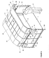
- Figures 1 to 4 show a container according to a first embodiment of the invention, intended in particular for the air transport of mail in bags and / or boxes.
- the container C1 comprises a support base 1, a metal frame comprising a lower frame 3, carrying two opposite rigid walls 5, and an upper roof frame 4.
- the support base 1 which defines the floor of the container C1, is formed in a known manner from a standard aircraft pallet consisting of a rectangular aluminum plate provided along its longitudinal and transverse edges 12 of a rail (not shown ) for fixing a net 10 for holding the sheet, by means of a pin system, as described below.
- the frame comprises a lower frame 3 comprising four corner posts 31-34 defining the lateral and longitudinal sides of the container C.
- the two so-called front corner posts referenced 31 and 32 define a front longitudinal side, the other two so-called rear corner posts referenced 33 and 34, defining a rear longitudinal side.
- the corner posts are fixed vertically to the four corners of the support base by means of brackets 35, 36.
- a first bracket 35 formed of an L-shaped section is attached along each transverse edge 12 of the support base 1 by a first wing.
- the two uprights (31, 33) and (32, 34) of the same lateral side are fixed on the second wing of a first bracket 35.
- the attachment of each corner post to the support base is completed by a second L-shaped bracket 36 fixed to the support base 1 and to the face of the post opposed to the first bracket 35.
- Each side panel comprises a plate 51, for example of composite plastic material, assembled by riveting to a metal frame formed of a lower bar 52 and an upper bar 53 interconnected by two vertical central bars 54.
- the upper and lower bars are welded to the corresponding corner posts, namely a corner post front and a rear corner post, parallel to the support base.
- the rigid frame further comprises an upper roof frame 4 comprising a frame 40 formed of two longitudinal sections 41 connected at the end by two lateral sections 42.
- the longitudinal sections have a central portion 41a extending by end portions 41b inclined down by relative to the central portion.
- the frame is stiffened by a central longitudinal section 43, of the same shape as the longitudinal profiles of the frame, connecting the two lateral sections 42.
- the longitudinal profiles of the frame are connected to the central longitudinal section at their central portions by a set of transverse spacers 44.
- the roof frame, the corner posts and the various bars of the lower frame may consist of aluminum profiles, for example of rectangular section, or aluminum tubes.
- the assembly means 6 of the roof frame on the lower frame comprises four arms 61-64 pivotally mounted by a first end at the four corners of the frame 40, and by their second end on the upper bar 53 of the rigid panels.
- the arms are arranged transversely and pivot about axes of rotation arranged longitudinally, parallel to the support base.
- the two arms 61, 62, said front, arranged on the front longitudinal side, are each pivotally mounted on a shoe 65 which is mounted to move in translation on a linear guide slide 66 assembled on the upper bar of a rigid panel.
- the other two arms 63, 64, said rear, the rear longitudinal side, are pivotally mounted by a hinge 67 fixedly mounted on the upper bar of the panels.
- the front and rear pivoting arms allow the roof frame to move between a raised position as shown in FIGS. 2, 3 and 4 and a low position, as illustrated in FIG.
- a pneumatic cylinder 68 is associated with each arm to resiliently bias the roof frame to its raised position.
- Each piston is pivotally assembled to a corner post by its cylinder and the end of the piston rod is pivotally assembled to a lateral frame section 42 near a corner of the frame.
- Locking means 7 are provided to keep the roof frame in its low position.
- these locking means comprise a projecting stud 71 on each corner post adapted to be inserted into the orifice of a tongue 72 fixed at one end to the corresponding inclined portion of the frame.
- the free end of the tongue is advantageously provided with a loop 73 to facilitate the locking / unlocking operation.
- the container C1 furthermore comprises a rigid intermediate partition 8 arranged longitudinally between the two lateral panels 5.
- the intermediate partition is advantageously slidably mounted between the two lateral panels to be displaced in translation in the transverse direction and is maintained at the desired position by means of appropriate positioning means.
- This partition similar in structure to that of the side panels, can be used to separate the internal volume of the container into two compartments, for example one for the bags and the other for the boxes, or serve as a rigid bottom wall for close the rear longitudinal side of the container.
- the upper edge 81 of this intermediate partition is adapted to the shape of the profiles longitudinals of the roof frame so as to ensure proper separation of the two compartments in the low position of said frame.
- the roof frame 4, and the two longitudinal sides are covered with a flexible coating or tarpaulin 9.
- the cover comprises a main portion 91 covering the roof frame, which is extended by longitudinal sections 92 extending beyond the longitudinal sections 41 to close the longitudinal sides of the container in the lower position of the roof frame.
- the sheet also extends beyond the lateral sections 42 by side panels 93 which partially cover the side panels to ensure the seal at the junction between the roof frame and said side panels in the lower position.
- roof frame Peripheral rods are provided along the lateral and longitudinal profiles of the frame to protect the cover. These rods are for example heat-sealed or glued to the inner face of the tarpaulin.
- the sheet is held on the roof frame by a net 10 comprising a network of longitudinal straps 101 and transverse 102 sewn on the sheet whose ends can be connected to the aforementioned peripheral rail of the support base 1.
- the transverse straps 102, 5 in the embodiment of the figures, extend along the longitudinal sides 92 and are each provided with a tensioning system 103 receiving the end of an assembly strap 104, the second end is equipped with a 105 standardized pawn system able to come snap into the peripheral rail of the support base.
- Each longitudinal pan comprises at least one longitudinal strap 110 fixed transversely to the assembly straps 104 and provided with hook 106 at its ends for its assembly to the corner posts by means of two-part connecting straps 107.
- the two parts of this connecting strap 107 are interconnected by a tensioning system 108, one of the two parts being attached to a corner post, while the other is provided with a ring 109 which is snap on a hook 106.
- the longitudinal straps 101 of the main part 91 of the cover extend beyond the side panels 93 and are provided at their end with tensioning systems 111 for their assembly. at the base support or pallet 1 by means of assembly straps 112 provided with a system of pins 105. These assembly straps 112 are connected by a transverse strap 113 whose ends may be provided with rings or hooks to allow its assembly to the corner posts, as previously described.
- the junction of the longitudinal flaps 92 and the main portion 91 at the level of the inclined end portions is provided by means of a Velcro-type assembly system, as schematically illustrated under the reference 94.
- the container may further comprise a set of handles 14 at the corner posts and the external faces of the side panels 5 for facilitate the handling of the container, as well as pouches 13 on the outer faces of the panels to receive documents.
- the transverse 102 and longitudinal straps 101, 110 of the net are initially relaxed by releasing the tensioning systems 108 and 111 of the four lateral sides of the container.
- the pin systems 105 of the assembly straps 104 on both longitudinal sides can then be disengaged from the rail and the rings 109 removed from the hooks 106.
- the longitudinal sections 92 of the sheet with the assembly straps provided with the pion systems are raised. , preferably two operators, and the assembly is placed on the roof frame, as shown schematically in Figures 2 and 3.
- the four tabs 72 are then disengaged from their respective pads 71 by pulling on the loops 73.
- FIGS. represent the container as a whole in open position, with the tarpaulin raised, the roof frame in the raised position.
- the pad 65 moves from the interior towards the outside along the slideway 66, the roof frame translating upward, perpendicularly to the support base 1, and forward parallel to the support base 1, so that the roof frame is slightly offset from the support base.
- the longitudinal straps 101 will be sufficiently relaxed to allow the complete deployment of the roof frame to its raised position.
- the roof frame In this raised position, the roof frame is sufficiently spaced from the support base to allow a person P to stand, as it appears in Figures 2 and 3.
- the height of the container defined by the distance between the longitudinal profiles of the frame and the support base, is about 1.50 meters in the low position of the roof frame, and about 1.85 meters in its raised position.
- the unloading / loading of the container can be performed in more ergonomic positions and faster.
- each compartment is accessible from one of the open longitudinal sides, one of the compartments can for example be used for the bags, the other for the bins. or boxes.
- the container according to the invention provided with a liftable roof frame, allows a time saving of the order of 10% for its filling.
- the transport of bins can be increased by about 7% compared to conventional containers.
- the container is closed as quickly as it is opened.
- the roof frame is returned to its lower position by pulling it down by the loops 73 of the tongues and by engaging the tabs on the pads 71, preferably those arranged on the side of the rear arms pivotally mounted on the upper bar, but without possibility of transverse sliding, then the other two disposed on the side of the front corner posts 31, 32.
- the longitudinal sections 92 are lowered, assembled to the main part 91 at the level of the inclined portions by the Velcro ® type system, the systems of the peg assembly straps engaged on the support base 1, the hooks 106 engaged on the rings 109 and all tensioning systems 103, 111 are actuated to tension the longitudinal and transverse straps.
- the use of a standard pallet and net in the development of the container according to the invention makes it possible to meet the safety standards in force in the field of air freight transport.
- the metal frame of the container must have sufficient rigidity to carry the sheet and ensure the displacement of the roof frame between its two positions.
- the tarpaulin carried by the frame makes it possible to obtain a perfectly sealed container.
- the container can be closed hermetically, without its contents being visible from the outside, and thus ensures a secure transport.
- the roof frame being covered with a rigid coating, such as aluminum panels or plastic.
- the longitudinal sides are also covered with rigid panels, said panels then being mounted movable on the frame, for example on the amounts by means of hinges, to allow access to the interior of the container.
- FIG. 5 illustrates an alternative embodiment of the assembly of the roof frame on the lower frame, in which the identical elements bear the same reference numerals.
- the assembly means 16 do not comprise a rear arm, these being replaced by simple hinges 163, 164 mounted on the upper end of the rear corner uprights 33, 34.
- the upper roof frame 4 simply performs a rotational movement about the axis of rotation of the two hinges arranged parallel to the support base.
- pneumatic cylinders 68 are associated with the arms 61, 62 before slidably mounted on the side panels 5 by means of slider 65 on slideway 66, to automatically raise the roof frame in its raised position illustrated in FIG.
- Access to the container then preferably takes place only on the longitudinal front side, the rear longitudinal side being closed by a rigid longitudinal panel 150, of structure similar to that of the side panels described above, mounted between the two rear pillars.
- the longitudinal panel 150 comprises a plate 151 mounted on a frame formed of an upper bar 152 and a lower bar 153 interconnected by three spacers 154.
- the upper bar whose shape corresponds to that of the longitudinal sections 41 of the frame 40, has a central portion 152a extending with inclined end portions 152b.
- the tarpaulin (not shown) then comprises a first longitudinal pan identical to that described above, to close the front longitudinal side, and a second longitudinal pan of sufficient length to ensure the overlap of the junction zone between the roof frame and the panel back.
Landscapes
- Engineering & Computer Science (AREA)
- Mechanical Engineering (AREA)
- Pallets (AREA)
- Catching Or Destruction (AREA)
- Auxiliary Methods And Devices For Loading And Unloading (AREA)
- Containers Having Bodies Formed In One Piece (AREA)
Claims (10)
- Frachtbehälter für Luftfracht, insbesondere für Postsendungen, enthaltend eine Tragunterlage (1), auf welche eine steife Bewehrung montiert ist, die ein unteres Gestell (3) aufweist, das an die Tragunterlage angefügt ist und die Seitenflächen des Behälters definiert, dadurch gekennzeichnet, dass die steife Bewehrung ein oberes Dachgestell (4) aufweist, das über Anfügemittel (6, 16) an das untere Gestell beweglich montiert ist, welche eine Verlagerung des oberen Dachgestells zwischen einer unteren Stellung und einer angehobenen Stellung gestatten, in welche das Gestell sich zumindest teilweise von der Tragunterlage abhebt, um das Beladen und Entladen des Behälters über zumindest eine zu öffnende Behälterseite zu vereinfachen.
- Frachtbehälter nach Anspruch 1, dadurch gekennzeichnet, dass das Dachgestell (4) aus einem Rahmen (40) gebildet ist, wobei die Anfügemittel zwei entgegengesetzte Profile des Rahmens mit dem unteren Gestell verbinden.
- Frachtbehälter nach Anspruch 2, dadurch gekennzeichnet, dass die Anfügemittel (6) derart sind, dass das Dachgestell zwischen seiner abgesenkten Stellung und seiner angehobenen Stellung translatorisch verschiebbar ist.
- Frachtbehälter nach Anspruch 2, dadurch gekennzeichnet, dass die Anfügemittel (16) den Rahmen (40) zwischen seinen beiden Stellungen durch eine Drehbewegung um eine im wesentlichen parallel zur Tragunterlage verlaufende Achse verlagern können.
- Frachtbehälter nach einem der Ansprüche 2 bis 4, dadurch gekennzeichnet, dass die Tragunterlage (1) eine allgemein rechteckige Form hat, wobei das untere Gestell (3) vier Eckstützen (31-34) aufweist, die an der Tragunterlage befestigt und paarweise über zumindest einen starren Stab (53) verbunden sind, und der Rahmen (40) zwei Längsprofile (41) aufweist, die endseitig über zwei Seitenprofile (42) verbunden sind, wobei die Anfügemittel (6, 16) die Seitenprofile mit den starren Stäben verbinden.
- Frachtbehälter nach den Ansprüchen 3 und 5, dadurch gekennzeichnet, dass jedes Seitenprofil (42) über zwei Arme mit einem starren Stab verbunden ist, die mit einem ersten Ende schwenkbeweglich am Seitenprofil gelagert und mit ihrem zweiten Ende schwenkbeweglich am Stab im Abstand von den Eckstützen (31-34) gelagert sind, wobei zumindest zwei Arme (61, 62), die auf der Seite eines gleichen Längsprofils angeordnet sind, schwenkbeweglich an einem Gleitschuh (65) gelagert sind, der verschiebbar an einer Gleitführung (66) gelagert ist, die an den starren Stab angefügt ist.
- Frachtbehälter nach den Ansprüchen 4 und 5, dadurch gekennzeichnet, dass jedes Seitenprofil (42) mit einem oberen Stab (53) des unteren Gestells über einen Arm verbunden ist, der mit einem ersten Ende schwenkbeweglich am Seitenprofil nahe bei einem ersten Längsprofil (41) gelagert ist und mit seinem zweiten Ende schwenkbeweglich an dem Stab gelagert ist, der an einer Gleitführung (66) verschiebbar gelagert ist, welche im Abstand von den Eckstützen über ein nahe bei dem zweiten Längsprofil befestigtes Scharnier (163) an den starren Stab angefügt ist.
- Frachtbehälter nach einem der vorangehenden Ansprüche, dadurch gekennzeichnet, dass er Federmittel (68) aufweist, welche das obere Dachgestell (4) in Richtung seiner angehobenen Stellung federnd verlagern können, sowie Mittel (7) zum Sichern des oberen Gestells in seiner geschlossenen unteren Stellung.
- Frachtbehälter nach einem der Ansprüche 5 bis 8, dadurch gekennzeichnet, dass jedes Paar von über einen starren Stab (53) verbundenen Eckstützen (61, 63; 62, 64) eine starre Wand (5) trägt, wobei der Behälter zwei zu öffnende entgegengesetzte Seiten aufweist, die von den Paaren nicht verbundener Eckstützen definiert werden, wobei das Dachgestell und die beiden zu öffnenden Seiten mit einer biegsamen Wand (9) überzogen sind, welche von einem Netz (10) gehalten wird, das aus einem Raster von quer und längs verlaufenden Gurten (101, 102) gebildet ist.
- Frachtbehälter nach einem der vorangehenden Ansprüche, dadurch gekennzeichnet, dass er eine innen liegende Trennwand (8) aufweist, die im wesentlichen parallel zu den zu öffnenden Seitenflächen verläuft.
Applications Claiming Priority (2)
| Application Number | Priority Date | Filing Date | Title |
|---|---|---|---|
| FR0312565 | 2003-10-28 | ||
| FR0312565A FR2861375B1 (fr) | 2003-10-28 | 2003-10-28 | Conteneur de fret. |
Publications (2)
| Publication Number | Publication Date |
|---|---|
| EP1528012A1 EP1528012A1 (de) | 2005-05-04 |
| EP1528012B1 true EP1528012B1 (de) | 2007-07-18 |
Family
ID=34400834
Family Applications (1)
| Application Number | Title | Priority Date | Filing Date |
|---|---|---|---|
| EP04364064A Expired - Lifetime EP1528012B1 (de) | 2003-10-28 | 2004-10-27 | Frachtbehälter für Luftfracht. |
Country Status (4)
| Country | Link |
|---|---|
| EP (1) | EP1528012B1 (de) |
| AT (1) | ATE367328T1 (de) |
| DE (1) | DE602004007595D1 (de) |
| FR (1) | FR2861375B1 (de) |
Families Citing this family (3)
| Publication number | Priority date | Publication date | Assignee | Title |
|---|---|---|---|---|
| WO2009036484A1 (en) * | 2007-09-17 | 2009-03-26 | Technosearch Pty Ltd | Improvements in folding containers |
| CA2639622C (en) | 2007-09-20 | 2014-05-20 | Mathieu Boivin | Collapsible container |
| US10759596B2 (en) | 2018-11-20 | 2020-09-01 | Satco, Inc. | Cargo container with dual mode doors |
Citations (1)
| Publication number | Priority date | Publication date | Assignee | Title |
|---|---|---|---|---|
| US5377856A (en) * | 1993-03-29 | 1995-01-03 | Brierton; Dennis M. | Air cargo security vault |
Family Cites Families (6)
| Publication number | Priority date | Publication date | Assignee | Title |
|---|---|---|---|---|
| US3186756A (en) * | 1961-08-18 | 1965-06-01 | Reynolds Metals Co | Cargo transporting vehicle construction |
| DE9305998U1 (de) * | 1993-04-13 | 1994-03-03 | Bunk, Kurt, 10553 Berlin | Abdeckung für Fahrzeug-Transportbehälter |
| DK173692B1 (da) * | 2000-05-05 | 2001-06-25 | Carrimor | Bundsektion til en foldecontainer |
| DK200101532A (da) * | 2001-10-18 | 2003-04-19 | Carrimor | Topvæg til en container |
| DE20207452U1 (de) * | 2002-05-11 | 2002-11-21 | Hüffermann Fahrzeugtechnik GmbH, 27793 Wildeshausen | Behälter für Reststoffe, Wertstoffe o.dgl. |
| DE20218054U1 (de) * | 2002-11-21 | 2003-03-06 | M. Sirch GmbH & Co. KG Apparate und Behälterbau, 87600 Kaufbeuren | Container |
-
2003
- 2003-10-28 FR FR0312565A patent/FR2861375B1/fr not_active Expired - Lifetime
-
2004
- 2004-10-27 AT AT04364064T patent/ATE367328T1/de not_active IP Right Cessation
- 2004-10-27 DE DE602004007595T patent/DE602004007595D1/de not_active Expired - Lifetime
- 2004-10-27 EP EP04364064A patent/EP1528012B1/de not_active Expired - Lifetime
Patent Citations (1)
| Publication number | Priority date | Publication date | Assignee | Title |
|---|---|---|---|---|
| US5377856A (en) * | 1993-03-29 | 1995-01-03 | Brierton; Dennis M. | Air cargo security vault |
Also Published As
| Publication number | Publication date |
|---|---|
| ATE367328T1 (de) | 2007-08-15 |
| DE602004007595D1 (de) | 2007-08-30 |
| FR2861375B1 (fr) | 2006-01-06 |
| FR2861375A1 (fr) | 2005-04-29 |
| EP1528012A1 (de) | 2005-05-04 |
Similar Documents
| Publication | Publication Date | Title |
|---|---|---|
| CA2937301C (fr) | Structure d'abri, en particulier d'un plateau de charge, tel qu'une plateforme de camion, de remorque ou similaire, et abri integrant une telle structure | |
| FR2500816A1 (fr) | Conteneur pliable et compressible | |
| WO2014033608A2 (fr) | Caisse metallique repliable | |
| WO2014072603A1 (fr) | Ensemble formant rampe d'acces pour des personnes a mobilite reduite et vehicule ainsi equipe | |
| FR2658146A1 (fr) | Dispositif de chariot mobile pliable multi-fonctions. | |
| FR2861375A1 (fr) | Conteneur de fret. | |
| FR2598897A1 (fr) | Bagage transformable en chariot | |
| EP1775160B1 (de) | Verdeckaufbau für eine Fläche, insbesondere eine Ladefläche | |
| EP1698513B1 (de) | Wechselbehälter mit eingebautem Leiter zur Aufnahme und zum Transport von Materialien | |
| EP0753383B1 (de) | Werkzeugkasten | |
| FR2935318A1 (fr) | Agencement d'etagere escamotable a l'interieur d'un vehicule | |
| FR2588827A1 (fr) | Dispositif de remplissage et de vidage pour conteneurs souples | |
| EP3400622B1 (de) | Stationärer schutzraum zur aufbewahrung von mindestens einer stromspeichereinheit | |
| WO2023131672A1 (fr) | Boite de transfert d'articles dans un carton | |
| FR2842150A1 (fr) | Agencement de sacs de transport sous une tablette arriere de vehicule automobile | |
| WO2018051267A1 (fr) | Chariot pliable pour faciliter les courses | |
| FR3010054A1 (fr) | Conteneur de manutention de produits | |
| EP0277880B1 (de) | Beförderungsvorrichtung, insbesondere für Selbstbedienungsläden | |
| FR2785251A1 (fr) | Chariot emboitable a compartiments | |
| FR2683794A1 (fr) | Palette metallique repliable pour la manutention de volets, de plateaux vantaux. | |
| EP2481639B1 (de) | Auskleidung für Heckkipplastwagen, mit einer solchen Auskleidung ausgestatteter Heckkipplastwagen sowie sein Belade- und Entladeverfahren | |
| EP0741052A1 (de) | Gestell zur Abdeckung eines Nutzfahrzeuges mit einer bewegbaren Runge | |
| FR2757831A1 (fr) | Palette de manutention d'objets longitudinaux | |
| FR2795709A1 (fr) | Module de stockage d'articles a elements de reception suspendus | |
| FR2527537A1 (fr) | Poussette equipee de deux sacs a provisions |
Legal Events
| Date | Code | Title | Description |
|---|---|---|---|
| PUAI | Public reference made under article 153(3) epc to a published international application that has entered the european phase |
Free format text: ORIGINAL CODE: 0009012 |
|
| AK | Designated contracting states |
Kind code of ref document: A1 Designated state(s): AT BE BG CH CY CZ DE DK EE ES FI FR GB GR HU IE IT LI LU MC NL PL PT RO SE SI SK TR |
|
| AX | Request for extension of the european patent |
Extension state: AL HR LT LV MK |
|
| 17P | Request for examination filed |
Effective date: 20051020 |
|
| AKX | Designation fees paid |
Designated state(s): AT BE BG CH CY CZ DE DK EE ES FI FR GB GR HU IE IT LI LU MC NL PL PT RO SE SI SK TR |
|
| GRAP | Despatch of communication of intention to grant a patent |
Free format text: ORIGINAL CODE: EPIDOSNIGR1 |
|
| GRAS | Grant fee paid |
Free format text: ORIGINAL CODE: EPIDOSNIGR3 |
|
| GRAA | (expected) grant |
Free format text: ORIGINAL CODE: 0009210 |
|
| AK | Designated contracting states |
Kind code of ref document: B1 Designated state(s): AT BE BG CH CY CZ DE DK EE ES FI FR GB GR HU IE IT LI LU MC NL PL PT RO SE SI SK TR |
|
| REG | Reference to a national code |
Ref country code: GB Ref legal event code: FG4D Free format text: NOT ENGLISH |
|
| REG | Reference to a national code |
Ref country code: CH Ref legal event code: EP |
|
| REF | Corresponds to: |
Ref document number: 602004007595 Country of ref document: DE Date of ref document: 20070830 Kind code of ref document: P |
|
| REG | Reference to a national code |
Ref country code: IE Ref legal event code: FG4D Free format text: LANGUAGE OF EP DOCUMENT: FRENCH |
|
| PG25 | Lapsed in a contracting state [announced via postgrant information from national office to epo] |
Ref country code: ES Free format text: LAPSE BECAUSE OF FAILURE TO SUBMIT A TRANSLATION OF THE DESCRIPTION OR TO PAY THE FEE WITHIN THE PRESCRIBED TIME-LIMIT Effective date: 20071029 Ref country code: FI Free format text: LAPSE BECAUSE OF FAILURE TO SUBMIT A TRANSLATION OF THE DESCRIPTION OR TO PAY THE FEE WITHIN THE PRESCRIBED TIME-LIMIT Effective date: 20070718 Ref country code: BG Free format text: LAPSE BECAUSE OF FAILURE TO SUBMIT A TRANSLATION OF THE DESCRIPTION OR TO PAY THE FEE WITHIN THE PRESCRIBED TIME-LIMIT Effective date: 20071018 Ref country code: NL Free format text: LAPSE BECAUSE OF FAILURE TO SUBMIT A TRANSLATION OF THE DESCRIPTION OR TO PAY THE FEE WITHIN THE PRESCRIBED TIME-LIMIT Effective date: 20070718 Ref country code: PT Free format text: LAPSE BECAUSE OF FAILURE TO SUBMIT A TRANSLATION OF THE DESCRIPTION OR TO PAY THE FEE WITHIN THE PRESCRIBED TIME-LIMIT Effective date: 20071218 |
|
| NLV1 | Nl: lapsed or annulled due to failure to fulfill the requirements of art. 29p and 29m of the patents act | ||
| GBV | Gb: ep patent (uk) treated as always having been void in accordance with gb section 77(7)/1977 [no translation filed] |
Effective date: 20070718 |
|
| PG25 | Lapsed in a contracting state [announced via postgrant information from national office to epo] |
Ref country code: PL Free format text: LAPSE BECAUSE OF FAILURE TO SUBMIT A TRANSLATION OF THE DESCRIPTION OR TO PAY THE FEE WITHIN THE PRESCRIBED TIME-LIMIT Effective date: 20070718 Ref country code: AT Free format text: LAPSE BECAUSE OF FAILURE TO SUBMIT A TRANSLATION OF THE DESCRIPTION OR TO PAY THE FEE WITHIN THE PRESCRIBED TIME-LIMIT Effective date: 20070718 |
|
| REG | Reference to a national code |
Ref country code: IE Ref legal event code: FD4D |
|
| BERE | Be: lapsed |
Owner name: LA POSTE (EXPLOITANT PUBLIC) Effective date: 20071031 |
|
| PG25 | Lapsed in a contracting state [announced via postgrant information from national office to epo] |
Ref country code: DK Free format text: LAPSE BECAUSE OF FAILURE TO SUBMIT A TRANSLATION OF THE DESCRIPTION OR TO PAY THE FEE WITHIN THE PRESCRIBED TIME-LIMIT Effective date: 20070718 Ref country code: GR Free format text: LAPSE BECAUSE OF FAILURE TO SUBMIT A TRANSLATION OF THE DESCRIPTION OR TO PAY THE FEE WITHIN THE PRESCRIBED TIME-LIMIT Effective date: 20071019 Ref country code: DE Free format text: LAPSE BECAUSE OF FAILURE TO SUBMIT A TRANSLATION OF THE DESCRIPTION OR TO PAY THE FEE WITHIN THE PRESCRIBED TIME-LIMIT Effective date: 20071019 |
|
| PLBE | No opposition filed within time limit |
Free format text: ORIGINAL CODE: 0009261 |
|
| STAA | Information on the status of an ep patent application or granted ep patent |
Free format text: STATUS: NO OPPOSITION FILED WITHIN TIME LIMIT |
|
| PG25 | Lapsed in a contracting state [announced via postgrant information from national office to epo] |
Ref country code: SK Free format text: LAPSE BECAUSE OF FAILURE TO SUBMIT A TRANSLATION OF THE DESCRIPTION OR TO PAY THE FEE WITHIN THE PRESCRIBED TIME-LIMIT Effective date: 20070718 Ref country code: CZ Free format text: LAPSE BECAUSE OF FAILURE TO SUBMIT A TRANSLATION OF THE DESCRIPTION OR TO PAY THE FEE WITHIN THE PRESCRIBED TIME-LIMIT Effective date: 20070718 Ref country code: GB Free format text: LAPSE BECAUSE OF FAILURE TO SUBMIT A TRANSLATION OF THE DESCRIPTION OR TO PAY THE FEE WITHIN THE PRESCRIBED TIME-LIMIT Effective date: 20070718 Ref country code: MC Free format text: LAPSE BECAUSE OF NON-PAYMENT OF DUE FEES Effective date: 20071031 Ref country code: IE Free format text: LAPSE BECAUSE OF FAILURE TO SUBMIT A TRANSLATION OF THE DESCRIPTION OR TO PAY THE FEE WITHIN THE PRESCRIBED TIME-LIMIT Effective date: 20070718 |
|
| 26N | No opposition filed |
Effective date: 20080421 |
|
| PG25 | Lapsed in a contracting state [announced via postgrant information from national office to epo] |
Ref country code: SE Free format text: LAPSE BECAUSE OF FAILURE TO SUBMIT A TRANSLATION OF THE DESCRIPTION OR TO PAY THE FEE WITHIN THE PRESCRIBED TIME-LIMIT Effective date: 20071018 Ref country code: RO Free format text: LAPSE BECAUSE OF FAILURE TO SUBMIT A TRANSLATION OF THE DESCRIPTION OR TO PAY THE FEE WITHIN THE PRESCRIBED TIME-LIMIT Effective date: 20070718 |
|
| PG25 | Lapsed in a contracting state [announced via postgrant information from national office to epo] |
Ref country code: BE Free format text: LAPSE BECAUSE OF NON-PAYMENT OF DUE FEES Effective date: 20071031 |
|
| REG | Reference to a national code |
Ref country code: FR Ref legal event code: ST Effective date: 20080630 |
|
| PG25 | Lapsed in a contracting state [announced via postgrant information from national office to epo] |
Ref country code: EE Free format text: LAPSE BECAUSE OF FAILURE TO SUBMIT A TRANSLATION OF THE DESCRIPTION OR TO PAY THE FEE WITHIN THE PRESCRIBED TIME-LIMIT Effective date: 20070718 |
|
| PG25 | Lapsed in a contracting state [announced via postgrant information from national office to epo] |
Ref country code: FR Free format text: LAPSE BECAUSE OF NON-PAYMENT OF DUE FEES Effective date: 20071031 |
|
| REG | Reference to a national code |
Ref country code: CH Ref legal event code: PL |
|
| PG25 | Lapsed in a contracting state [announced via postgrant information from national office to epo] |
Ref country code: SI Free format text: LAPSE BECAUSE OF FAILURE TO SUBMIT A TRANSLATION OF THE DESCRIPTION OR TO PAY THE FEE WITHIN THE PRESCRIBED TIME-LIMIT Effective date: 20070718 |
|
| PG25 | Lapsed in a contracting state [announced via postgrant information from national office to epo] |
Ref country code: CY Free format text: LAPSE BECAUSE OF FAILURE TO SUBMIT A TRANSLATION OF THE DESCRIPTION OR TO PAY THE FEE WITHIN THE PRESCRIBED TIME-LIMIT Effective date: 20070718 |
|
| PG25 | Lapsed in a contracting state [announced via postgrant information from national office to epo] |
Ref country code: LU Free format text: LAPSE BECAUSE OF NON-PAYMENT OF DUE FEES Effective date: 20071027 |
|
| PG25 | Lapsed in a contracting state [announced via postgrant information from national office to epo] |
Ref country code: TR Free format text: LAPSE BECAUSE OF FAILURE TO SUBMIT A TRANSLATION OF THE DESCRIPTION OR TO PAY THE FEE WITHIN THE PRESCRIBED TIME-LIMIT Effective date: 20070718 Ref country code: HU Free format text: LAPSE BECAUSE OF FAILURE TO SUBMIT A TRANSLATION OF THE DESCRIPTION OR TO PAY THE FEE WITHIN THE PRESCRIBED TIME-LIMIT Effective date: 20080119 |
|
| PG25 | Lapsed in a contracting state [announced via postgrant information from national office to epo] |
Ref country code: CH Free format text: LAPSE BECAUSE OF NON-PAYMENT OF DUE FEES Effective date: 20081031 Ref country code: LI Free format text: LAPSE BECAUSE OF NON-PAYMENT OF DUE FEES Effective date: 20081031 |
|
| PG25 | Lapsed in a contracting state [announced via postgrant information from national office to epo] |
Ref country code: IT Free format text: LAPSE BECAUSE OF NON-PAYMENT OF DUE FEES Effective date: 20071031 |