EP1528012B1 - Air cargo container. - Google Patents
Air cargo container. Download PDFInfo
- Publication number
- EP1528012B1 EP1528012B1 EP04364064A EP04364064A EP1528012B1 EP 1528012 B1 EP1528012 B1 EP 1528012B1 EP 04364064 A EP04364064 A EP 04364064A EP 04364064 A EP04364064 A EP 04364064A EP 1528012 B1 EP1528012 B1 EP 1528012B1
- Authority
- EP
- European Patent Office
- Prior art keywords
- subframe
- rigid
- container
- frame
- container according
- Prior art date
- Legal status (The legal status is an assumption and is not a legal conclusion. Google has not performed a legal analysis and makes no representation as to the accuracy of the status listed.)
- Not-in-force
Links
- 229910052782 aluminium Inorganic materials 0.000 description 6
- XAGFODPZIPBFFR-UHFFFAOYSA-N aluminium Chemical compound [Al] XAGFODPZIPBFFR-UHFFFAOYSA-N 0.000 description 6
- 238000005192 partition Methods 0.000 description 6
- 210000002105 tongue Anatomy 0.000 description 4
- 229910052751 metal Inorganic materials 0.000 description 3
- 239000002184 metal Substances 0.000 description 3
- 230000002093 peripheral effect Effects 0.000 description 3
- 239000011248 coating agent Substances 0.000 description 2
- 238000000576 coating method Methods 0.000 description 2
- 230000002787 reinforcement Effects 0.000 description 2
- 125000006850 spacer group Chemical group 0.000 description 2
- 241000920340 Pion Species 0.000 description 1
- 239000002131 composite material Substances 0.000 description 1
- 238000006073 displacement reaction Methods 0.000 description 1
- 230000000694 effects Effects 0.000 description 1
- 239000000463 material Substances 0.000 description 1
- 238000000926 separation method Methods 0.000 description 1
Images


Classifications
-
- B—PERFORMING OPERATIONS; TRANSPORTING
- B65—CONVEYING; PACKING; STORING; HANDLING THIN OR FILAMENTARY MATERIAL
- B65D—CONTAINERS FOR STORAGE OR TRANSPORT OF ARTICLES OR MATERIALS, e.g. BAGS, BARRELS, BOTTLES, BOXES, CANS, CARTONS, CRATES, DRUMS, JARS, TANKS, HOPPERS, FORWARDING CONTAINERS; ACCESSORIES, CLOSURES, OR FITTINGS THEREFOR; PACKAGING ELEMENTS; PACKAGES
- B65D88/00—Large containers
- B65D88/02—Large containers rigid
- B65D88/12—Large containers rigid specially adapted for transport
- B65D88/122—Large containers rigid specially adapted for transport with access from above
- B65D88/124—Large containers rigid specially adapted for transport with access from above closable top
- B65D88/126—Large containers rigid specially adapted for transport with access from above closable top by rigid element, e.g. lid
-
- B—PERFORMING OPERATIONS; TRANSPORTING
- B65—CONVEYING; PACKING; STORING; HANDLING THIN OR FILAMENTARY MATERIAL
- B65D—CONTAINERS FOR STORAGE OR TRANSPORT OF ARTICLES OR MATERIALS, e.g. BAGS, BARRELS, BOTTLES, BOXES, CANS, CARTONS, CRATES, DRUMS, JARS, TANKS, HOPPERS, FORWARDING CONTAINERS; ACCESSORIES, CLOSURES, OR FITTINGS THEREFOR; PACKAGING ELEMENTS; PACKAGES
- B65D88/00—Large containers
- B65D88/02—Large containers rigid
- B65D88/12—Large containers rigid specially adapted for transport
- B65D88/14—Large containers rigid specially adapted for transport by air
Definitions
- the present invention relates to a freight container.
- the invention relates more particularly to a cargo container for air transport, particularly for the transport of mail.
- a container is described in the document US Patent 5377856 .
- the air transport of mail is carried out conventionally in bags or in stackable bins or boxes placed in containers, commonly called igloos.
- containers comprise a support base defining the floor of the container and on which is mounted a rigid frame formed of aluminum profiles and defining the lateral sides and the roof of the container.
- the container comprises an open side, reclosable by a tarpaulin held by straps, the other three sides and the roof being closed by rigid panels of aluminum or plastic fixed to the frame.
- the support base is conventionally formed of an aircraft pallet of standardized dimensions.
- the dimensions of the frame must conform to those of the aircraft cabin, the height of the igloos being generally of the order of 1.50 meters.
- the purpose of the present invention is to provide a container to improve the working conditions of the staff responsible for loading / unloading containers, allowing in particular to perform the loading and unloading in conditions of speed and ergonomics acceptable , while taking into account the dimensions imposed by air transport and increase the ferry load.
- the subject of the invention is a freight container comprising a support base on which a rigid reinforcement is mounted, characterized in that the said rigid reinforcement comprises a lower frame, assembled to the support base, which defines the lateral sides. of the container, and an upper roof frame movably mounted on the lower frame by means of assembly adapted to allow movement of said upper roof frame between a low position and a raised position in which said frame deviates at least partially from the support base for facilitating the loading and unloading of the container by at least one openable side of the container.
- the container comprises a lifting roof frame so that, in its raised position, a person can stand in the container, at least on a part of the base support.
- a liftable roof frame allows easier and faster handling of bags or boxes in more ergonomic positions. It has been established that the container according to the invention allows a time saving of the order of 10% for its filling. Furthermore, the liftable roof frame ensures optimal filling of the total internal volume of the container, which can in particular to gain a stacking step in the case of boxes.
- the roof frame is formed of a frame, said connecting means connecting two opposite sections of said frame to said lower frame.
- the assembly means are such that said roof frame is moved in translation between its lowered position and its raised position.
- the assembly means are able to move said frame so that the lowered and raised positions of the frame are parallel, advantageously, said frame is substantially parallel to the support base in its two positions.
- the assembly means are able to move said frame between its two positions by a rotational movement about an axis substantially parallel to the support base, so that, advantageously, said frame is inclined by relative to the support base in its raised position.
- the support base has a generally rectangular shape
- the lower frame comprises four corner posts fixed on the support base, connected in pairs by at least one bar rigid
- the frame comprises two longitudinal sections connected at the end by two lateral sections, the assembly means connecting the side sections to said rigid bars.
- each lateral profile can then be connected to a rigid bar by two pivotally mounted arms by a first end to said lateral section and pivotally mounted by their second end on said bar at a distance from the corner posts, at least two arms arranged on the side of the same longitudinal section being pivotally mounted on a shoe mounted to move in translation on an assembled slide on the rigid bar.
- only two arms are slidably mounted on upper bar, the two other arms being pivotally mounted on the upper bar by a fixed hinge so that, between its two positions, the roof frame moves in translation perpendicularly. and parallel to the support base, the roof frame being offset laterally above the support base in its raised position.
- each lateral section can be connected to an upper bar of the lower frame by an arm pivotally mounted by a first end on the lateral section near a first longitudinal section, and is pivotally mounted by its second end. on the bar mounted movably in translation on an assembled slide on the rigid bar, away from the corner posts, and by a hinge fixed near the second longitudinal section.
- the freight container comprises elastic means, such as pneumatic cylinders for example, able to elastically move the upper roof frame to its raised position, and locking means of the upper frame in its closed down position.
- elastic means such as pneumatic cylinders for example, able to elastically move the upper roof frame to its raised position, and locking means of the upper frame in its closed down position.
- each pair of corner posts connected by a rigid bar carries a rigid wall, said container comprising two opposite sides defined by the pairs of unbound corner posts, the roof frame and the two working sides. being coated with a flexible wall held by a net formed of a network of transverse and longitudinal straps.
- the container comprises an inner partition wall, substantially parallel to the lateral sides open, preferably slidably mounted between the two rigid walls.
- Figures 1 to 4 show a container according to a first embodiment of the invention, intended in particular for the air transport of mail in bags and / or boxes.
- the container C1 comprises a support base 1, a metal frame comprising a lower frame 3, carrying two opposite rigid walls 5, and an upper roof frame 4.
- the support base 1 which defines the floor of the container C1, is formed in a known manner from a standard aircraft pallet consisting of a rectangular aluminum plate provided along its longitudinal and transverse edges 12 of a rail (not shown ) for fixing a net 10 for holding the sheet, by means of a pin system, as described below.
- the frame comprises a lower frame 3 comprising four corner posts 31-34 defining the lateral and longitudinal sides of the container C.
- the two so-called front corner posts referenced 31 and 32 define a front longitudinal side, the other two so-called rear corner posts referenced 33 and 34, defining a rear longitudinal side.
- the corner posts are fixed vertically to the four corners of the support base by means of brackets 35, 36.
- a first bracket 35 formed of an L-shaped section is attached along each transverse edge 12 of the support base 1 by a first wing.
- the two uprights (31, 33) and (32, 34) of the same lateral side are fixed on the second wing of a first bracket 35.
- the attachment of each corner post to the support base is completed by a second L-shaped bracket 36 fixed to the support base 1 and to the face of the post opposed to the first bracket 35.
- Each side panel comprises a plate 51, for example of composite plastic material, assembled by riveting to a metal frame formed of a lower bar 52 and an upper bar 53 interconnected by two vertical central bars 54.
- the upper and lower bars are welded to the corresponding corner posts, namely a corner post front and a rear corner post, parallel to the support base.
- the rigid frame further comprises an upper roof frame 4 comprising a frame 40 formed of two longitudinal sections 41 connected at the end by two lateral sections 42.
- the longitudinal sections have a central portion 41a extending by end portions 41b inclined down by relative to the central portion.
- the frame is stiffened by a central longitudinal section 43, of the same shape as the longitudinal profiles of the frame, connecting the two lateral sections 42.
- the longitudinal profiles of the frame are connected to the central longitudinal section at their central portions by a set of transverse spacers 44.
- the roof frame, the corner posts and the various bars of the lower frame may consist of aluminum profiles, for example of rectangular section, or aluminum tubes.
- the assembly means 6 of the roof frame on the lower frame comprises four arms 61-64 pivotally mounted by a first end at the four corners of the frame 40, and by their second end on the upper bar 53 of the rigid panels.
- the arms are arranged transversely and pivot about axes of rotation arranged longitudinally, parallel to the support base.
- the two arms 61, 62, said front, arranged on the front longitudinal side, are each pivotally mounted on a shoe 65 which is mounted to move in translation on a linear guide slide 66 assembled on the upper bar of a rigid panel.
- the other two arms 63, 64, said rear, the rear longitudinal side, are pivotally mounted by a hinge 67 fixedly mounted on the upper bar of the panels.
- the front and rear pivoting arms allow the roof frame to move between a raised position as shown in FIGS. 2, 3 and 4 and a low position, as illustrated in FIG.
- a pneumatic cylinder 68 is associated with each arm to resiliently bias the roof frame to its raised position.
- Each piston is pivotally assembled to a corner post by its cylinder and the end of the piston rod is pivotally assembled to a lateral frame section 42 near a corner of the frame.
- Locking means 7 are provided to keep the roof frame in its low position.
- these locking means comprise a projecting stud 71 on each corner post adapted to be inserted into the orifice of a tongue 72 fixed at one end to the corresponding inclined portion of the frame.
- the free end of the tongue is advantageously provided with a loop 73 to facilitate the locking / unlocking operation.
- the container C1 furthermore comprises a rigid intermediate partition 8 arranged longitudinally between the two lateral panels 5.
- the intermediate partition is advantageously slidably mounted between the two lateral panels to be displaced in translation in the transverse direction and is maintained at the desired position by means of appropriate positioning means.
- This partition similar in structure to that of the side panels, can be used to separate the internal volume of the container into two compartments, for example one for the bags and the other for the boxes, or serve as a rigid bottom wall for close the rear longitudinal side of the container.
- the upper edge 81 of this intermediate partition is adapted to the shape of the profiles longitudinals of the roof frame so as to ensure proper separation of the two compartments in the low position of said frame.
- the roof frame 4, and the two longitudinal sides are covered with a flexible coating or tarpaulin 9.
- the cover comprises a main portion 91 covering the roof frame, which is extended by longitudinal sections 92 extending beyond the longitudinal sections 41 to close the longitudinal sides of the container in the lower position of the roof frame.
- the sheet also extends beyond the lateral sections 42 by side panels 93 which partially cover the side panels to ensure the seal at the junction between the roof frame and said side panels in the lower position.
- roof frame Peripheral rods are provided along the lateral and longitudinal profiles of the frame to protect the cover. These rods are for example heat-sealed or glued to the inner face of the tarpaulin.
- the sheet is held on the roof frame by a net 10 comprising a network of longitudinal straps 101 and transverse 102 sewn on the sheet whose ends can be connected to the aforementioned peripheral rail of the support base 1.
- the transverse straps 102, 5 in the embodiment of the figures, extend along the longitudinal sides 92 and are each provided with a tensioning system 103 receiving the end of an assembly strap 104, the second end is equipped with a 105 standardized pawn system able to come snap into the peripheral rail of the support base.
- Each longitudinal pan comprises at least one longitudinal strap 110 fixed transversely to the assembly straps 104 and provided with hook 106 at its ends for its assembly to the corner posts by means of two-part connecting straps 107.
- the two parts of this connecting strap 107 are interconnected by a tensioning system 108, one of the two parts being attached to a corner post, while the other is provided with a ring 109 which is snap on a hook 106.
- the longitudinal straps 101 of the main part 91 of the cover extend beyond the side panels 93 and are provided at their end with tensioning systems 111 for their assembly. at the base support or pallet 1 by means of assembly straps 112 provided with a system of pins 105. These assembly straps 112 are connected by a transverse strap 113 whose ends may be provided with rings or hooks to allow its assembly to the corner posts, as previously described.
- the junction of the longitudinal flaps 92 and the main portion 91 at the level of the inclined end portions is provided by means of a Velcro-type assembly system, as schematically illustrated under the reference 94.
- the container may further comprise a set of handles 14 at the corner posts and the external faces of the side panels 5 for facilitate the handling of the container, as well as pouches 13 on the outer faces of the panels to receive documents.
- the transverse 102 and longitudinal straps 101, 110 of the net are initially relaxed by releasing the tensioning systems 108 and 111 of the four lateral sides of the container.
- the pin systems 105 of the assembly straps 104 on both longitudinal sides can then be disengaged from the rail and the rings 109 removed from the hooks 106.
- the longitudinal sections 92 of the sheet with the assembly straps provided with the pion systems are raised. , preferably two operators, and the assembly is placed on the roof frame, as shown schematically in Figures 2 and 3.
- the four tabs 72 are then disengaged from their respective pads 71 by pulling on the loops 73.
- FIGS. represent the container as a whole in open position, with the tarpaulin raised, the roof frame in the raised position.
- the pad 65 moves from the interior towards the outside along the slideway 66, the roof frame translating upward, perpendicularly to the support base 1, and forward parallel to the support base 1, so that the roof frame is slightly offset from the support base.
- the longitudinal straps 101 will be sufficiently relaxed to allow the complete deployment of the roof frame to its raised position.
- the roof frame In this raised position, the roof frame is sufficiently spaced from the support base to allow a person P to stand, as it appears in Figures 2 and 3.
- the height of the container defined by the distance between the longitudinal profiles of the frame and the support base, is about 1.50 meters in the low position of the roof frame, and about 1.85 meters in its raised position.
- the unloading / loading of the container can be performed in more ergonomic positions and faster.
- each compartment is accessible from one of the open longitudinal sides, one of the compartments can for example be used for the bags, the other for the bins. or boxes.
- the container according to the invention provided with a liftable roof frame, allows a time saving of the order of 10% for its filling.
- the transport of bins can be increased by about 7% compared to conventional containers.
- the container is closed as quickly as it is opened.
- the roof frame is returned to its lower position by pulling it down by the loops 73 of the tongues and by engaging the tabs on the pads 71, preferably those arranged on the side of the rear arms pivotally mounted on the upper bar, but without possibility of transverse sliding, then the other two disposed on the side of the front corner posts 31, 32.
- the longitudinal sections 92 are lowered, assembled to the main part 91 at the level of the inclined portions by the Velcro ® type system, the systems of the peg assembly straps engaged on the support base 1, the hooks 106 engaged on the rings 109 and all tensioning systems 103, 111 are actuated to tension the longitudinal and transverse straps.
- the use of a standard pallet and net in the development of the container according to the invention makes it possible to meet the safety standards in force in the field of air freight transport.
- the metal frame of the container must have sufficient rigidity to carry the sheet and ensure the displacement of the roof frame between its two positions.
- the tarpaulin carried by the frame makes it possible to obtain a perfectly sealed container.
- the container can be closed hermetically, without its contents being visible from the outside, and thus ensures a secure transport.
- the roof frame being covered with a rigid coating, such as aluminum panels or plastic.
- the longitudinal sides are also covered with rigid panels, said panels then being mounted movable on the frame, for example on the amounts by means of hinges, to allow access to the interior of the container.
- FIG. 5 illustrates an alternative embodiment of the assembly of the roof frame on the lower frame, in which the identical elements bear the same reference numerals.
- the assembly means 16 do not comprise a rear arm, these being replaced by simple hinges 163, 164 mounted on the upper end of the rear corner uprights 33, 34.
- the upper roof frame 4 simply performs a rotational movement about the axis of rotation of the two hinges arranged parallel to the support base.
- pneumatic cylinders 68 are associated with the arms 61, 62 before slidably mounted on the side panels 5 by means of slider 65 on slideway 66, to automatically raise the roof frame in its raised position illustrated in FIG.
- Access to the container then preferably takes place only on the longitudinal front side, the rear longitudinal side being closed by a rigid longitudinal panel 150, of structure similar to that of the side panels described above, mounted between the two rear pillars.
- the longitudinal panel 150 comprises a plate 151 mounted on a frame formed of an upper bar 152 and a lower bar 153 interconnected by three spacers 154.
- the upper bar whose shape corresponds to that of the longitudinal sections 41 of the frame 40, has a central portion 152a extending with inclined end portions 152b.
- the tarpaulin (not shown) then comprises a first longitudinal pan identical to that described above, to close the front longitudinal side, and a second longitudinal pan of sufficient length to ensure the overlap of the junction zone between the roof frame and the panel back.
Abstract
Description
La présente invention concerne un conteneur de fret. L'invention concerne plus particulièrement un conteneur de fret pour le transport aérien, notamment pour le transport de courrier. Un tel conteneur est décrit dans le document
Le transport aérien de courrier s'effectue de manière classique dans des sacs ou dans des bacs ou caissettes gerbables placés dans des conteneurs , appelés couramment igloos. De tels conteneurs comprennent une base support définissant le plancher du conteneur et sur laquelle est montée une armature rigide formée de profilés en aluminium et définissant les côtés latéraux et le toit du conteneur. Le conteneur comprend un côté ouvert, refermable par une bâche maintenue par des sangles, les trois autres côtés et le toit étant fermés par des panneaux rigides en aluminium ou en matière plastique fixés sur l'armature. La base support est formée classiquement d'une palette avion de dimensions normalisées. Par ailleurs, les dimensions de l'armature doivent se conformer à celles de la carlingue des avions, la hauteur des igloos étant généralement de l'ordre de 1,50 mètres.The air transport of mail is carried out conventionally in bags or in stackable bins or boxes placed in containers, commonly called igloos. Such containers comprise a support base defining the floor of the container and on which is mounted a rigid frame formed of aluminum profiles and defining the lateral sides and the roof of the container. The container comprises an open side, reclosable by a tarpaulin held by straps, the other three sides and the roof being closed by rigid panels of aluminum or plastic fixed to the frame. The support base is conventionally formed of an aircraft pallet of standardized dimensions. In addition, the dimensions of the frame must conform to those of the aircraft cabin, the height of the igloos being generally of the order of 1.50 meters.
Pour le chargement et le déchargement du courrier par le côté ouvert, en particulier dans le cas de caissettes gerbables qui à terme vont remplacer les sacs, il est nécessaire qu'une personne pénètre dans le conteneur. En raison des dimensions des conteneurs, la manutention du courrier dans les conteneurs s'effectue difficilement et dans des positions peu ergonomiques. Par ailleurs, dans le domaine du fret aérien, le personnel dispose de peu de temps pour charger/décharger les conteneurs, et les dimensions du conteneur ne facilitent pas la rapidité d'exécution de ces opérations.For the loading and unloading of mail by the open side, especially in the case of stackable boxes that will eventually replace the bags, it is necessary that a person enters the container. Because of the size of the containers, the handling of the mail in the containers is difficult and in positions that are not very ergonomic. Moreover, in the field of air freight, the There is little time for staff to load / unload the containers, and the dimensions of the container do not facilitate the speed of these operations.
Le but de la présente invention est de proposer un conteneur permettant d'améliorer les conditions de travail du personnel responsable du chargement/déchargement des conteneurs, permettant en particulier d'accomplir le chargement et le déchargement dans des conditions de rapidité et d'ergonomie acceptables, tout en tenant compte des dimensions imposées par le transport aérien et d'augmenter l'emport de bac.The purpose of the present invention is to provide a container to improve the working conditions of the staff responsible for loading / unloading containers, allowing in particular to perform the loading and unloading in conditions of speed and ergonomics acceptable , while taking into account the dimensions imposed by air transport and increase the ferry load.
A cet effet, l'invention a pour objet un conteneur de fret comprenant une base support sur laquelle est montée une armature rigide, caractérisé par le fait que ladite armature rigide comprend un châssis inférieur, assemblé à la base support, qui définit les côtés latéraux du conteneur, et un châssis de toit supérieur monté mobile sur le châssis inférieur par des moyens d'assemblage aptes à permettre un déplacement dudit châssis de toit supérieur entre une position basse et une position relevée dans laquelle ledit châssis s'écarte au moins partiellement de la base support pour faciliter le chargement et déchargement du conteneur par au moins un côté ouvrable du conteneur.For this purpose, the subject of the invention is a freight container comprising a support base on which a rigid reinforcement is mounted, characterized in that the said rigid reinforcement comprises a lower frame, assembled to the support base, which defines the lateral sides. of the container, and an upper roof frame movably mounted on the lower frame by means of assembly adapted to allow movement of said upper roof frame between a low position and a raised position in which said frame deviates at least partially from the support base for facilitating the loading and unloading of the container by at least one openable side of the container.
Selon l'invention, le conteneur comprend un châssis de toit relevable de sorte que, dans sa position relevée, une personne puisse se tenir debout dans le conteneur, au moins sur une partie de la base support. Un tel châssis de toit relevable permet une manutention plus aisée et plus rapide des sacs ou caissettes, dans des positions plus ergonomiques. Il a été établi que le conteneur selon l'invention permet un gain de temps de l'ordre de 10% pour son remplissage. Par ailleurs, le châssis de toit relevable assure un remplissage optimal du volume interne total du conteneur, pouvant permettre notamment de gagner un pas de gerbage dans le cas de caissettes.According to the invention, the container comprises a lifting roof frame so that, in its raised position, a person can stand in the container, at least on a part of the base support. Such a liftable roof frame allows easier and faster handling of bags or boxes in more ergonomic positions. It has been established that the container according to the invention allows a time saving of the order of 10% for its filling. Furthermore, the liftable roof frame ensures optimal filling of the total internal volume of the container, which can in particular to gain a stacking step in the case of boxes.
Selon une particularité, le châssis de toit est formé d'un cadre, lesdits moyens d'assemblage reliant deux profilés opposés dudit cadre audit châssis inférieur.According to one feature, the roof frame is formed of a frame, said connecting means connecting two opposite sections of said frame to said lower frame.
Dans un premier mode de réalisation, les moyens d'assemblage sont tels que ledit châssis de toit est déplacé en translation entre sa position abaissée et sa position relevée. Les moyens d'assemblages sont aptes à déplacer ledit cadre de sorte que les positions abaissée et relevée du cadre sont parallèles, avantageusement, ledit cadre est sensiblement parallèle à la base support dans ses deux positions.In a first embodiment, the assembly means are such that said roof frame is moved in translation between its lowered position and its raised position. The assembly means are able to move said frame so that the lowered and raised positions of the frame are parallel, advantageously, said frame is substantially parallel to the support base in its two positions.
Dans un deuxième mode de réalisation, les moyens d'assemblage sont aptes à déplacer ledit cadre entre ses deux positions par un mouvement de rotation autour d'un axe sensiblement parallèle à la base support, de sorte que, avantageusement, ledit cadre soit incliné par rapport à la base support dans sa position relevée.In a second embodiment, the assembly means are able to move said frame between its two positions by a rotational movement about an axis substantially parallel to the support base, so that, advantageously, said frame is inclined by relative to the support base in its raised position.
Selon une autre particularité, la base support a une forme générale rectangulaire, le châssis inférieur comprend quatre montants d'angle fixés sur la base support, reliés deux à deux par au moins une barre rigide, et le cadre comprend deux profilés longitudinaux reliés en extrémité par deux profilés latéraux, les moyens d'assemblage reliant les profilés latéraux auxdites barres rigides.According to another feature, the support base has a generally rectangular shape, the lower frame comprises four corner posts fixed on the support base, connected in pairs by at least one bar rigid, and the frame comprises two longitudinal sections connected at the end by two lateral sections, the assembly means connecting the side sections to said rigid bars.
Dans le premier mode de réalisation, chaque profilé latéral peut alors être relié à une barre rigide par deux bras montés pivotants par une première extrémité audit profilé latéral et montés pivotants par leur deuxième extrémité sur ladite barre à distance des montants d'angle, au moins deux bras disposés du côté d'un même profilé longitudinal étant montés pivotants sur un patin monté mobile en translation sur une glissière assemblée sur la barre rigide. Selon un mode de réalisation particulier, seuls deux bras sont montés coulissants sur barre supérieure, les deux autres bras étant montés pivotants sur la barre supérieure par une articulation fixe de sorte que, entre ses deux positions, le châssis de toit se déplace en translation perpendiculairement et parallèlement à la base support, le châssis de toit étant décalé latéralement au-dessus de la base support dans sa position relevée.In the first embodiment, each lateral profile can then be connected to a rigid bar by two pivotally mounted arms by a first end to said lateral section and pivotally mounted by their second end on said bar at a distance from the corner posts, at least two arms arranged on the side of the same longitudinal section being pivotally mounted on a shoe mounted to move in translation on an assembled slide on the rigid bar. According to a particular embodiment, only two arms are slidably mounted on upper bar, the two other arms being pivotally mounted on the upper bar by a fixed hinge so that, between its two positions, the roof frame moves in translation perpendicularly. and parallel to the support base, the roof frame being offset laterally above the support base in its raised position.
Dans le deuxième mode de réalisation, chaque profilé latéral peut être relié à une barre supérieure du châssis inférieur par un bras monté pivotant par une première extrémité sur le profilé latéral à proximité d'un premier profilé longitudinal, et est monté pivotant par sa deuxième extrémité sur la barre montée mobile en translation sur une glissière assemblée sur la barre rigide, à distance des montants d'angle, et par une charnière fixée à proximité du deuxième profilé longitudinal.In the second embodiment, each lateral section can be connected to an upper bar of the lower frame by an arm pivotally mounted by a first end on the lateral section near a first longitudinal section, and is pivotally mounted by its second end. on the bar mounted movably in translation on an assembled slide on the rigid bar, away from the corner posts, and by a hinge fixed near the second longitudinal section.
Avantageusement le conteneur de fret comprend des moyens élastiques, tels que des vérins pneumatiques par exemple, aptes à déplacer élastiquement le châssis de toit supérieur vers sa position relevée, et des moyens de blocage du châssis supérieur dans sa position basse fermée.Advantageously, the freight container comprises elastic means, such as pneumatic cylinders for example, able to elastically move the upper roof frame to its raised position, and locking means of the upper frame in its closed down position.
Selon une autre particularité, chaque paire de montants d'angle reliés par une barre rigide porte une paroi rigide, ledit conteneur comprenant deux côtés ouvrables opposés définis par les paires de montants d'angle non reliés, le châssis de toit et les deux côtés ouvrables étant revêtus d'une paroi flexible maintenue par un filet formé d'un réseau de sangles transversales et longitudinales.According to another particularity, each pair of corner posts connected by a rigid bar carries a rigid wall, said container comprising two opposite sides defined by the pairs of unbound corner posts, the roof frame and the two working sides. being coated with a flexible wall held by a net formed of a network of transverse and longitudinal straps.
Selon une autre particularité, le conteneur comprend une paroi interne de séparation, sensiblement parallèle aux côtés latéraux ouvrables, de préférence montée coulissante entre les deux parois rigides.According to another feature, the container comprises an inner partition wall, substantially parallel to the lateral sides open, preferably slidably mounted between the two rigid walls.
L'invention sera mieux comprise, et d'autres buts, détails, caractéristiques et avantages apparaîtront plus clairement au cours de la description explicative détaillée qui va suivre de deux modes de réalisation particuliers actuellement préférés de l'invention, en référence au dessin schématique annexé.The invention will be better understood, and other objects, details, features and advantages will become more clearly apparent from the following detailed explanatory description of two presently preferred particular embodiments of the invention, with reference to the attached schematic drawing. .
Sur ce dessin :
- la figure 1 représente une vue en perspective d'un conteneur de fret aérien en position fermée selon un premier mode de réalisation ;
- la figure 2 représente une vue en perspective du conteneur de la figure 1 en position ouverte et toit relevé ;
- la figure 3 représente une vue de côté du conteneur de la figure 2 ;
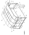
- la figure 4 représente le conteneur de la figure 2, en l'absence du filet et de la bâche, illustrant l'armature rigide du conteneur avec le châssis de toit dans sa position relevée ; et,
- la figure 5 représente une vue en perspective d'un conteneur selon un deuxième mode de réalisation, en l'absence du filet et de la bâche.
- FIG. 1 represents a perspective view of an air cargo container in the closed position according to a first embodiment;
- Figure 2 shows a perspective view of the container of Figure 1 in the open position and roof raised;
- Figure 3 shows a side view of the container of Figure 2;
- Figure 4 shows the container of Figure 2, in the absence of the net and the sheet, illustrating the rigid frame of the container with the roof frame in its raised position; and,
- Figure 5 shows a perspective view of a container according to a second embodiment, in the absence of the net and the cover.
Les figures 1 à 4 représentent un conteneur selon un premier mode de réalisation de l'invention, destiné en particulier au transport aérien de courrier dans des sacs et/ou caissettes. Le conteneur C1 comprend une base support 1, une armature métallique comprenant un châssis inférieur 3, portant deux parois rigides 5 opposées, et un châssis de toit supérieur 4.Figures 1 to 4 show a container according to a first embodiment of the invention, intended in particular for the air transport of mail in bags and / or boxes. The container C1 comprises a
La base support 1, qui définit le plancher du conteneur C1, est formée de manière connue d'une palette avion normalisée constituée d'une plaque rectangulaire en aluminium munie le long de ses bords longitudinaux 11 et transversaux 12 d'un rail (non représenté) pour la fixation d'un filet 10 de maintien de la bâche, au moyen de système de pion, tel que décrit ci-après.The
Tel qu'illustré en particulier à la figure 4, l'armature comporte un châssis inférieur 3 comprenant quatre montants d'angle 31-34 définissant les côtés latéraux et longitudinaux du conteneur C. Les deux montants d'angle dits avant référencés 31 et 32, définissent un côté longitudinal avant, les deux autres montants d'angle dits arrière référencés 33 et 34, définissant un côté longitudinal arrière. Les montants d'angle sont fixés verticalement aux quatre coins de la base support au moyen d'équerres 35, 36. Une première équerre 35 formée d'un profilé en L est fixée le long de chaque bord transversal 12 de la base support 1 par une première aile. Les deux montants (31, 33) et (32, 34) d'un même côté latéral sont fixés sur la deuxième aile d'une première équerre 35. La fixation de chaque montant d'angle sur la base support est complétée par une deuxième équerre en L 36 fixée à la base support 1 et à la face du montant opposée à la première équerre 35.As illustrated in particular in Figure 4, the frame comprises a
Les côtés latéraux sont fermés par des parois rigides formées par des panneaux latéraux 5 fixés entre deux montants d'angle et le long de la deuxième aile des équerres 36. Chaque panneau latéral comprend une plaque 51, par exemple en matériau plastique composite, assemblée par rivetage à une armature métallique formée d'une barre inférieure 52 et une barre supérieure 53 reliées entre elles par deux barres centrales verticales 54. Les barres supérieure et inférieure sont assemblées par soudure aux montants d'angle correspondant, à savoir un montant d'angle avant et un montant d'angle arrière, parallèlement à la base support.The lateral sides are closed by rigid walls formed by
L'armature rigide comprend en outre un châssis de toit supérieur 4 comprenant un cadre 40 formé de deux profilés longitudinaux 41 reliés en extrémité par deux profilés latéraux 42. Les profilés longitudinaux présentent une portion centrale 41a se prolongeant par des portions d'extrémité 41b inclinées vers le bas par rapport à la portion centrale. Le cadre est rigidifié par un profilé longitudinal central 43, de même forme que les profilés longitudinaux du cadre, reliant les deux profilés latéraux 42. Les profilés longitudinaux du cadre sont reliés au profilé longitudinal central au niveau de leur portions centrales par un ensemble d'entretoises transversales 44.The rigid frame further comprises an
Le châssis de toit, les montants d'angle et les diverses barres du châssis inférieur peuvent être constitués de profilés en aluminium, par exemple de section rectangulaire, ou de tubes en aluminium.The roof frame, the corner posts and the various bars of the lower frame may consist of aluminum profiles, for example of rectangular section, or aluminum tubes.
Les moyens d'assemblage 6 du châssis de toit sur le châssis inférieur comprennent quatre bras 61-64 montés pivotants par une première extrémité aux quatre coins du cadre 40, et par leur deuxième extrémité sur la barre supérieure 53 des panneaux rigides. Les bras sont disposés transversalement et pivotent autour d'axes de rotation disposés longitudinalement, parallèlement à la base support.The assembly means 6 of the roof frame on the lower frame comprises four arms 61-64 pivotally mounted by a first end at the four corners of the
Les deux bras 61, 62, dit avant, disposés du côté longitudinal avant, sont chacun montés pivotants sur un patin 65 qui est monté mobile en translation sur une glissière 66 de guidage linéaire assemblée sur la barre supérieure d'un panneau rigide. Les deux autres bras 63, 64, dit arrière, du côté longitudinal arrière, sont montés pivotants par une articulation 67 montée fixe sur la barre supérieure des panneaux. Comme décrit ci-après, les bras pivotants avant et arrière permettent le déplacement du châssis de toit entre une position relevée telle qu'illustrée aux figures 2, 3 et 4 et une position basse, telle qu'illustrée à la figure 1.The two
Un vérin pneumatique 68 est associé à chaque bras pour solliciter élastiquement le châssis de toit vers sa position relevée. Chaque piston est assemblé de manière pivotante à un montant d'angle par son cylindre et l'extrémité de la tige du piston est assemblée de manière pivotante sur un profilé latéral 42 du cadre, à proximité d'un coin du cadre.A
Des moyens de blocage 7 sont prévus pour maintenir le châssis de toit dans sa position basse. Dans cet exemple de réalisation, ces moyens de blocage comprennent un plot saillant 71 sur chaque montant d'angle apte à venir s'insérer dans l'orifice d'une languette 72 fixée par une extrémité à la portion inclinée correspondante du cadre. L'extrémité libre de la languette est avantageusement munie d'une boucle 73 pour faciliter l'opération de blocage/déblocage.Locking means 7 are provided to keep the roof frame in its low position. In this embodiment, these locking means comprise a projecting
Le conteneur C1 comprend par ailleurs une cloison intermédiaire rigide 8 disposée longitudinalement entre les deux panneaux latéraux 5. La cloison intermédiaire est avantageusement montée coulissante entre les deux panneaux latéraux pour être déplacée en translation dans la direction transversale et est maintenue à la position désirée par des moyens de positionnement appropriés. Cette cloison, de structure similaire de celle des panneaux latéraux, peut être utilisée pour séparer le volume interne du conteneur en deux compartiments, par exemple l'un pour les sacs et l'autre pour les caissettes, ou servir de paroi de fond rigide pour fermer le côté longitudinal arrière du conteneur. Le bord supérieur 81 de cette cloison intermédiaire est adapté à la forme des profilés longitudinaux du châssis de toit de manière à garantir une séparation correcte des deux compartiments dans la position basse dudit châssis.The container C1 furthermore comprises a rigid
En référence à la figure 1, le châssis de toit 4, ainsi que les deux côtés longitudinaux sont recouverts d'un revêtement flexible ou bâche 9. La bâche comprend une partie principale 91 recouvrant le châssis de toit, qui se prolonge par des pans longitudinaux 92 s'étendant au-delà des profilés longitudinaux 41 pour fermer les côtés longitudinaux du conteneur dans la position basse du châssis de toit. La bâche se prolonge par ailleurs au-delà des profilés latéraux 42 par des pans latéraux 93 qui recouvrent partiellement les panneaux latéraux afin d'assurer l'étanchéité au niveau de la jonction entre le châssis de toit et lesdits panneaux latéraux dans la position basse du châssis de toit. Des joncs périphériques sont prévus le long des profilés latéraux et longitudinaux du cadre pour protéger la bâche. Ces joncs sont par exemple thermosoudés ou collés sur la face interne de la bâche.Referring to Figure 1, the
La bâche est maintenue sur le châssis de toit par un filet 10 comprenant un réseau de sangles longitudinales 101 et transversales 102 cousues sur la bâche dont les extrémités peuvent être reliées au rail périphérique précité de la base support 1.The sheet is held on the roof frame by a net 10 comprising a network of
Les sangles transversales 102, au nombre de 5 sur le mode de réalisation des figures, se prolongent le long des pans longitudinaux 92 et sont chacune munie d'un système tendeur 103 recevant l'extrémité d'une sangle d'assemblage 104 dont la deuxième extrémité est munie d'un système de pion normalisé 105 apte à venir s'enclencher dans le rail périphérique de la base support. Chaque pan longitudinal comprend au moins une sangle longitudinale 110 fixée transversalement aux sangles d'assemblage 104 et munie de crochet 106 à ses extrémités pour son assemblage aux montants d'angle au moyen de sangles d'assemblage 107 en deux parties. Les deux parties de cette sangle d'assemblage 107 sont reliées entre elles par un système tendeur 108, l'une des deux parties étant fixée à un montant d'angle, tandis que l'autre est munie d'un anneau 109 venant s'enclencher sur un crochet 106.The
Les sangles longitudinales 101 de la partie principale 91 de la bâche, au nombre de trois dans le mode de réalisation illustré sur les figures, s'étendent au-delà des pans latéraux 93 et sont munies à leur extrémité de systèmes tendeurs 111 pour leur assemblage à la base support ou palette 1 au moyen de sangles d'assemblage 112 munies de système de pion 105. Ces sangles d'assemblage 112 sont reliées par une sangle transversale 113 dont les extrémités peuvent être munies d'anneaux ou de crochets pour permettre son assemblage aux montants d'angle, tel que décrit précédemment.The
La jonction des pans longitudinaux 92 et de la partie principale 91 au niveau des portions d'extrémité inclinées est assurée au moyen d'un système d'assemblage de type Velcro, tel qu'illustré schématiquement sous la référence 94.The junction of the
Le conteneur peut par ailleurs comprendre un ensemble de poignées 14 au niveau des montants d'angle et des faces externes des panneaux latéraux 5 pour faciliter la manutention du conteneur, ainsi que des pochettes 13 sur les faces externes des panneaux pour recevoir des documents.The container may further comprise a set of
Le mode d'utilisation du conteneur va à présent être décrit. Pour ouvrir le conteneur initialement en position fermée, tel qu'illustré à la figure 1, les sangles transversales 102 et longitudinales 101, 110 du filet sont dans un premier temps détendues en libérant les systèmes tendeurs 108 et 111 des quatre côtés latéraux du conteneur. Les systèmes de pion 105 des sangles d'assemblage 104 des deux côtés longitudinaux peuvent alors être désenclenchés du rail et les anneaux 109 retirés des crochets 106. Les pans longitudinaux 92 de la bâche avec les sangles d'assemblage munies des systèmes de pion sont relevés, de préférence à deux opérateurs, et l'ensemble est posé sur le châssis de toit, tel que représenté schématiquement sur les figures 2 et 3. Les quatre languettes 72 sont alors désenclenchées de leurs plots 71 respectifs en tirant sur les boucles 73. De préférence, on manoeuvre dans un premier temps les languettes disposées du côté des montants d'angle avant 31, 32, à savoir du côté des bras 61, 62 montés coulissants sur le châssis inférieur, puis les deux autres languettes disposées du côté des montants d'angle arrière 33, 34. Le châssis de toit 4 ainsi libéré se soulève automatiquement vers sa position relevée sous l'effet des vérins pneumatiques 68. Les figures 2 et 3 représentent le conteneur dans son ensemble en position ouverte, avec la bâche relevée, le châssis de toit en position relevée. Lors de ce déploiement, le patin 65 se déplace de l'intérieur vers l'extérieur le long de la glissière 66, le châssis de toit effectuant un mouvement de translation vers le haut, perpendiculairement à la base support 1, et vers l'avant parallèlement à la base support 1, de sorte que le châssis de toit est légèrement décalé par rapport à la base support. Les sangles longitudinales 101 seront suffisamment détendues pour permettre le déploiement complet du châssis de toit vers sa position relevée.The mode of use of the container will now be described. To open the container initially in the closed position, as shown in Figure 1, the transverse 102 and
Dans cette position relevée, le châssis de toit est suffisamment écarté de la base support pour permettre à une personne P de se tenir debout, tel qu'il apparaît sur les figures 2 et 3. A titre d'exemple, la hauteur du conteneur, définie par la distance entre les profilés longitudinaux du cadre et la base support, est d'environ 1,50 mètres dans la position basse du châssis de toit, et d'environ 1,85 mètres dans sa position relevée. Ainsi, le déchargement/chargement du conteneur peut s'effectuer dans des positions plus ergonomiques et plus rapidement. Dans le cas de l'utilisation de la cloison intermédiaire 8 pour former deux compartiments, chaque compartiment est accessible depuis l'un des côtés longitudinaux ouverts, l'un des compartiments pouvant par exemple être utilisé pour les sacs, l'autre pour les bacs ou caissettes. Tel qu'indiqué précédemment, le conteneur selon l'invention, muni d'un châssis de toit relevable, permet un gain de temps de l'ordre de 10% pour son remplissage. Par ailleurs, l'emport de bacs peut être augmenté de l'ordre de 7% par rapport à des conteneurs classiques.In this raised position, the roof frame is sufficiently spaced from the support base to allow a person P to stand, as it appears in Figures 2 and 3. For example, the height of the container, defined by the distance between the longitudinal profiles of the frame and the support base, is about 1.50 meters in the low position of the roof frame, and about 1.85 meters in its raised position. Thus, the unloading / loading of the container can be performed in more ergonomic positions and faster. In the case of the use of the
Une fois le chargement et/ou déchargement terminé, la fermeture du conteneur s'effectue aussi rapidement que son ouverture. Le châssis de toit est ramené dans sa position basse en le tirant vers le bas par les boucles 73 des languettes et en enclenchant les languettes sur les plots 71, de préférence celles disposées du côté des bras arrière montés pivotants sur la barre supérieure, mais sans possibilité de coulissement transversal, puis les deux autres disposées du côté des montants d'angle avant 31, 32. Les pans longitudinaux 92 sont abaissés, assemblés à la partie principale 91 au niveau des portions inclinées par le système de type Velcro ®, les systèmes de pion des sangles s'assemblage enclenchés sur la base support 1, les crochets 106 enclenchés sur les anneaux 109 et tous les systèmes tendeur 103, 111 sont actionnés pour tendre les sangles longitudinales et transversales.Once the loading and / or unloading is completed, the container is closed as quickly as it is opened. The roof frame is returned to its lower position by pulling it down by the
Dans le cas du transport aérien, l'utilisation d'une palette et d'un filet normalisés dans l'élaboration du conteneur selon l'invention permet de satisfaire les normes de sécurité en vigueur en matière de transport aérien de fret. L'armature métallique du conteneur doit présenter une rigidité suffisante pour porter la bâche et assurer le déplacement du châssis de toit entre ses deux positions. La bâche portée par l'armature permet d'obtenir un conteneur parfaitement étanche. Par ailleurs, le conteneur peut être fermé de façon hermétique, sans que son contenu soit visible de l'extérieur, et assure donc un transport sécurisé.In the case of air transport, the use of a standard pallet and net in the development of the container according to the invention makes it possible to meet the safety standards in force in the field of air freight transport. The metal frame of the container must have sufficient rigidity to carry the sheet and ensure the displacement of the roof frame between its two positions. The tarpaulin carried by the frame makes it possible to obtain a perfectly sealed container. Furthermore, the container can be closed hermetically, without its contents being visible from the outside, and thus ensures a secure transport.
En variante, seuls les deux côtés longitudinaux sont recouverts par une bâche, le châssis de toit étant recouvert d'un revêtement rigide, tel que des panneaux en aluminium ou en matière plastique. Dans une autre variante, les côtés longitudinaux sont également recouverts de panneaux rigides, lesdits panneaux étant alors montés mobiles sur l'armature, par exemple sur les montants au moyen de charnières, pour permettre l'accès à l'intérieur du conteneur.Alternatively, only the two longitudinal sides are covered by a tarpaulin, the roof frame being covered with a rigid coating, such as aluminum panels or plastic. In another variant, the longitudinal sides are also covered with rigid panels, said panels then being mounted movable on the frame, for example on the amounts by means of hinges, to allow access to the interior of the container.
La figure 5 illustre une variante de réalisation de l'assemblage du châssis de toit sur le châssis inférieur, dans laquelle les éléments identiques portent les mêmes chiffres de référence. Dans cette variante, les moyens d'assemblages 16 ne comprennent pas de bras arrière, ceux-ci étant remplacés par de simples charnières 163, 164 montées sur l'extrémité supérieure des montants d'angle arrière 33, 34. Lors de son déplacement entre ses deux positions, le châssis de toit supérieur 4 effectue simplement un mouvement de rotation autour de l'axe de rotation des deux charnières disposé parallèlement à la base support. Comme précédemment, des vérins pneumatiques 68 sont associés aux bras 61, 62 avant montés coulissants sur les panneaux latéraux 5 par l'intermédiaire de patin 65 sur glissière 66, pour relever automatiquement le châssis de toit dans sa position relevée illustrée à la figure 5. L'accès au conteneur s'effectue alors de préférence uniquement du côté longitudinal avant, le côté longitudinal arrière étant fermé par un panneau longitudinal rigide 150, de structure similaire à celle des panneaux latéraux décrits précédemment, monté entre les deux montants arrière. Le panneau longitudinal 150 comprend une plaque 151 montée sur une armature formée d'une barre supérieure 152 et d'une barre inférieure 153 reliées entre elles par trois entretoises 154. La barre supérieure, dont la forme correspond à celle des profilés longitudinaux 41 du cadre 40, présente une partie centrale 152a se prolongeant par des portions d'extrémité inclinées 152b. La bâche (non représentée) comprend alors un premier pan longitudinal identique à celui décrit précédemment, pour fermer le côté longitudinal avant, et un second pan longitudinal de longueur suffisante pour assurer le recouvrement de la zone de jonction entre le châssis de toit et le panneau arrière.FIG. 5 illustrates an alternative embodiment of the assembly of the roof frame on the lower frame, in which the identical elements bear the same reference numerals. In this variant, the assembly means 16 do not comprise a rear arm, these being replaced by
Claims (10)
- Cargo container for air transport, particularly for the transport of mail, comprising a supporting base (1) on which is mounted a rigid framework that comprises a lower subframe (3) connected to the supporting base and defining the lateral sides of the container, the container being characterized in that said rigid framework comprises an upper roof subframe (4) mounted movably on the lower subframe by connecting means (6, 16) such as to allow movement of said upper roof subframe, between a lower position and a raised position, in which latter position said subframe moves at least partially off the supporting base to facilitate loading and unloading the container through at least one openable side of the container.
- Cargo container according to Claim 1, characterized in that the roof subframe (4) is formed by a skeleton (40), said connecting means connecting two opposed sections of said skeleton to said lower subframe.
- Cargo container according to Claim 2, characterized in that the connecting means (6) are such that said roof subframe is moved translationally between its lowered position and its raised position.
- Cargo container according to Claim 2, characterized in that the connecting means (16) are capable of moving said skeleton (40) between its two positions by a rotational movement about an axis essentially parallel to the supporting base.
- Cargo container according to one of Claims 2 to 4, characterized in that the supporting base (1) is of generally rectangular shape, the lower subframe (3) comprises four corner posts (31-34) fixed to the supporting base and connected in pairs by at least one rigid bar (53) each, the skeleton (40) comprises two longitudinal sections (41) whose ends are connected together by two lateral sections (42), and the connecting means (6, 16) connects the lateral sections to said rigid bars.
- Cargo container according to Claims 3 and 5, characterized in that each lateral section (42) is connected to a rigid bar by two arms hinged at a first end to said lateral section and at their second end to said bar at a distance from the corner posts (31-34), of which arms at least two (61, 62), both adjacent to the same longitudinal section, are hinged to a shoe (65) mounted with translational mobility on a track (66) connected to the rigid bar.
- Cargo container according to Claims 4 and 5, characterized in that each lateral section (42) is connected to an upper bar (53) of the lower subframe by an arm hinged at a first end to the lateral section near a first longitudinal section (41), and at its second end to the bar mounted with translational mobility on a track (66) connected to the rigid bar, at a distance from the corner posts, and by a hinge (163) fixed near the second longitudinal section.
- Cargo container according to one of the preceding claims, characterized in that it comprises elastically acting means (68) for moving the upper roof subframe (4) elastically towards its raised position, and locking means (7) for locking the upper subframe in its closed lower position.
- Cargo container according to one of Claims 5 to 8, characterized in that each pair of corner posts (61, 63; 62, 64) connected by a rigid bar (53) supports a rigid wall (5), said container comprising two opposite openable sides defined by the non-connected pairs of corner posts, and the roof subframe and both openable sides being covered by a flexible wall (9) held in place by a net (10) made up of transverse and longitudinal straps (101, 102).
- Container according to one of the preceding claims, characterized in that it includes an internal dividing wall (8) approximately parallel to the openable lateral sides.
Applications Claiming Priority (2)
| Application Number | Priority Date | Filing Date | Title |
|---|---|---|---|
| FR0312565A FR2861375B1 (en) | 2003-10-28 | 2003-10-28 | FREIGHT CONTAINER. |
| FR0312565 | 2003-10-28 |
Publications (2)
| Publication Number | Publication Date |
|---|---|
| EP1528012A1 EP1528012A1 (en) | 2005-05-04 |
| EP1528012B1 true EP1528012B1 (en) | 2007-07-18 |
Family
ID=34400834
Family Applications (1)
| Application Number | Title | Priority Date | Filing Date |
|---|---|---|---|
| EP04364064A Not-in-force EP1528012B1 (en) | 2003-10-28 | 2004-10-27 | Air cargo container. |
Country Status (4)
| Country | Link |
|---|---|
| EP (1) | EP1528012B1 (en) |
| AT (1) | ATE367328T1 (en) |
| DE (1) | DE602004007595D1 (en) |
| FR (1) | FR2861375B1 (en) |
Families Citing this family (3)
| Publication number | Priority date | Publication date | Assignee | Title |
|---|---|---|---|---|
| EP2203364A4 (en) * | 2007-09-17 | 2012-04-25 | Technosearch Pty | Improvements in folding containers |
| US8960468B2 (en) | 2007-09-20 | 2015-02-24 | Norduyn Inc. | Collapsible container |
| US10759596B2 (en) | 2018-11-20 | 2020-09-01 | Satco, Inc. | Cargo container with dual mode doors |
Citations (1)
| Publication number | Priority date | Publication date | Assignee | Title |
|---|---|---|---|---|
| US5377856A (en) * | 1993-03-29 | 1995-01-03 | Brierton; Dennis M. | Air cargo security vault |
Family Cites Families (6)
| Publication number | Priority date | Publication date | Assignee | Title |
|---|---|---|---|---|
| US3186756A (en) * | 1961-08-18 | 1965-06-01 | Reynolds Metals Co | Cargo transporting vehicle construction |
| DE9305998U1 (en) * | 1993-04-13 | 1994-03-03 | Bunk Kurt | Cover for vehicle transport container |
| DK173692B1 (en) * | 2000-05-05 | 2001-06-25 | Carrimor | Base section for a folding container |
| DK200101532A (en) * | 2001-10-18 | 2003-04-19 | Carrimor | Top wall for a container |
| DE20207452U1 (en) * | 2002-05-11 | 2002-11-21 | Hueffermann Fahrzeugtech Gmbh | Containers for residues, recyclables or the like. |
| DE20218054U1 (en) * | 2002-11-21 | 2003-03-06 | Sirch Gmbh & Co Kg App Und Beh | Container for transporting by lorry and rail has whole roof opened so that transverse axis when roof is open is orientated perpendicularly, whereby opening mechanism is located above doors on container's narrow side |
-
2003
- 2003-10-28 FR FR0312565A patent/FR2861375B1/en not_active Expired - Lifetime
-
2004
- 2004-10-27 AT AT04364064T patent/ATE367328T1/en not_active IP Right Cessation
- 2004-10-27 DE DE602004007595T patent/DE602004007595D1/en active Active
- 2004-10-27 EP EP04364064A patent/EP1528012B1/en not_active Not-in-force
Patent Citations (1)
| Publication number | Priority date | Publication date | Assignee | Title |
|---|---|---|---|---|
| US5377856A (en) * | 1993-03-29 | 1995-01-03 | Brierton; Dennis M. | Air cargo security vault |
Also Published As
| Publication number | Publication date |
|---|---|
| DE602004007595D1 (en) | 2007-08-30 |
| FR2861375B1 (en) | 2006-01-06 |
| FR2861375A1 (en) | 2005-04-29 |
| EP1528012A1 (en) | 2005-05-04 |
| ATE367328T1 (en) | 2007-08-15 |
Similar Documents
| Publication | Publication Date | Title |
|---|---|---|
| FR2977229A1 (en) | Tricycle for transporting handicapped people i.e. people in wheel chair, in urban environment, has fasteners attached with receiving pieces in removable manner, where receiving pieces are fixed on part of frame of tricycle | |
| CA2937301C (en) | Canopy structure, in particular for a loading platform, such as a truck flatbed, trailer flatbed or the like, and canopy incorporating such a structure | |
| EP1698513B1 (en) | Exchangeable container, with integrated ladder, for storing and transporting material | |
| FR2500816A1 (en) | FOLDABLE AND COMPRESSIBLE CONTAINER | |
| EP2917069B1 (en) | Assembly forming an access ramp for persons with reduced mobility and vehicle equipped therewith | |
| EP1775160B1 (en) | Covering structure for a surface, in particular a loading platform | |
| EP1528012B1 (en) | Air cargo container. | |
| FR2658146A1 (en) | Multi-function folding mobile trolley device | |
| FR2598897A1 (en) | Luggage which can be converted into a trolley | |
| WO2023131672A1 (en) | Transfer box for transferring articles into a carboard box | |
| FR2922733A1 (en) | Package i.e. briefcase for use during traveling in e.g. aircraft, has four wheels that are mounted on base of lower half frame, and telescopic pulling handle mounted slidingly on side of lower half frame | |
| EP0753383B1 (en) | Tool-box | |
| FR2588827A1 (en) | Filling and emptying device for flexible containers | |
| EP1382490A1 (en) | Arrangement of bags under the luggage compartment cover of a motor vehicle | |
| FR3010054A1 (en) | CONTAINER FOR HANDLING PRODUCTS | |
| EP0277880B1 (en) | Handling device, in particular for self-service shops | |
| FR2935318A1 (en) | Retractable shelf arrangement for panel van, has shelf whose board has front part suspended by arms to slider in horizontal position, and arms placed in nearly horizontal position when board is in vertical position | |
| EP2481639B1 (en) | Lining for rear-unloading dump truck body, equipped with such a lining and loading/unloading method therefore | |
| FR2785251A1 (en) | Trolley for carrying merchandise has collapsible shelving frame attached to trapezoidal wheeled base | |
| FR2683794A1 (en) | Folding metal pallet for handling shutters and door leaves | |
| FR2757831A1 (en) | Pallet for handling tall articles, e.g. doors or window frames | |
| FR2733727A1 (en) | UTILITY VEHICLE INCLUDING A COVER WITH A MOBILE RANCHER | |
| FR2795709A1 (en) | Storage module for articles comprises shelves with suspension assemblies using bars arranged through loops in flexible straps with synchronized vertical movement. | |
| FR2527537A1 (en) | Two wheeled shopping trolley - has bag for purchases and another folding one which can also be used | |
| FR2801042A1 (en) | Foldable container for rail-road transport of merchandise has base panel with folding frame supporting flexible envelope to allow folding flat |
Legal Events
| Date | Code | Title | Description |
|---|---|---|---|
| PUAI | Public reference made under article 153(3) epc to a published international application that has entered the european phase |
Free format text: ORIGINAL CODE: 0009012 |
|
| AK | Designated contracting states |
Kind code of ref document: A1 Designated state(s): AT BE BG CH CY CZ DE DK EE ES FI FR GB GR HU IE IT LI LU MC NL PL PT RO SE SI SK TR |
|
| AX | Request for extension of the european patent |
Extension state: AL HR LT LV MK |
|
| 17P | Request for examination filed |
Effective date: 20051020 |
|
| AKX | Designation fees paid |
Designated state(s): AT BE BG CH CY CZ DE DK EE ES FI FR GB GR HU IE IT LI LU MC NL PL PT RO SE SI SK TR |
|
| GRAP | Despatch of communication of intention to grant a patent |
Free format text: ORIGINAL CODE: EPIDOSNIGR1 |
|
| GRAS | Grant fee paid |
Free format text: ORIGINAL CODE: EPIDOSNIGR3 |
|
| GRAA | (expected) grant |
Free format text: ORIGINAL CODE: 0009210 |
|
| AK | Designated contracting states |
Kind code of ref document: B1 Designated state(s): AT BE BG CH CY CZ DE DK EE ES FI FR GB GR HU IE IT LI LU MC NL PL PT RO SE SI SK TR |
|
| REG | Reference to a national code |
Ref country code: GB Ref legal event code: FG4D Free format text: NOT ENGLISH |
|
| REG | Reference to a national code |
Ref country code: CH Ref legal event code: EP |
|
| REF | Corresponds to: |
Ref document number: 602004007595 Country of ref document: DE Date of ref document: 20070830 Kind code of ref document: P |
|
| REG | Reference to a national code |
Ref country code: IE Ref legal event code: FG4D Free format text: LANGUAGE OF EP DOCUMENT: FRENCH |
|
| PG25 | Lapsed in a contracting state [announced via postgrant information from national office to epo] |
Ref country code: ES Free format text: LAPSE BECAUSE OF FAILURE TO SUBMIT A TRANSLATION OF THE DESCRIPTION OR TO PAY THE FEE WITHIN THE PRESCRIBED TIME-LIMIT Effective date: 20071029 Ref country code: FI Free format text: LAPSE BECAUSE OF FAILURE TO SUBMIT A TRANSLATION OF THE DESCRIPTION OR TO PAY THE FEE WITHIN THE PRESCRIBED TIME-LIMIT Effective date: 20070718 Ref country code: BG Free format text: LAPSE BECAUSE OF FAILURE TO SUBMIT A TRANSLATION OF THE DESCRIPTION OR TO PAY THE FEE WITHIN THE PRESCRIBED TIME-LIMIT Effective date: 20071018 Ref country code: NL Free format text: LAPSE BECAUSE OF FAILURE TO SUBMIT A TRANSLATION OF THE DESCRIPTION OR TO PAY THE FEE WITHIN THE PRESCRIBED TIME-LIMIT Effective date: 20070718 Ref country code: PT Free format text: LAPSE BECAUSE OF FAILURE TO SUBMIT A TRANSLATION OF THE DESCRIPTION OR TO PAY THE FEE WITHIN THE PRESCRIBED TIME-LIMIT Effective date: 20071218 |
|
| NLV1 | Nl: lapsed or annulled due to failure to fulfill the requirements of art. 29p and 29m of the patents act | ||
| GBV | Gb: ep patent (uk) treated as always having been void in accordance with gb section 77(7)/1977 [no translation filed] |
Effective date: 20070718 |
|
| PG25 | Lapsed in a contracting state [announced via postgrant information from national office to epo] |
Ref country code: PL Free format text: LAPSE BECAUSE OF FAILURE TO SUBMIT A TRANSLATION OF THE DESCRIPTION OR TO PAY THE FEE WITHIN THE PRESCRIBED TIME-LIMIT Effective date: 20070718 Ref country code: AT Free format text: LAPSE BECAUSE OF FAILURE TO SUBMIT A TRANSLATION OF THE DESCRIPTION OR TO PAY THE FEE WITHIN THE PRESCRIBED TIME-LIMIT Effective date: 20070718 |
|
| REG | Reference to a national code |
Ref country code: IE Ref legal event code: FD4D |
|
| BERE | Be: lapsed |
Owner name: LA POSTE (EXPLOITANT PUBLIC) Effective date: 20071031 |
|
| PG25 | Lapsed in a contracting state [announced via postgrant information from national office to epo] |
Ref country code: DK Free format text: LAPSE BECAUSE OF FAILURE TO SUBMIT A TRANSLATION OF THE DESCRIPTION OR TO PAY THE FEE WITHIN THE PRESCRIBED TIME-LIMIT Effective date: 20070718 Ref country code: GR Free format text: LAPSE BECAUSE OF FAILURE TO SUBMIT A TRANSLATION OF THE DESCRIPTION OR TO PAY THE FEE WITHIN THE PRESCRIBED TIME-LIMIT Effective date: 20071019 Ref country code: DE Free format text: LAPSE BECAUSE OF FAILURE TO SUBMIT A TRANSLATION OF THE DESCRIPTION OR TO PAY THE FEE WITHIN THE PRESCRIBED TIME-LIMIT Effective date: 20071019 |
|
| PLBE | No opposition filed within time limit |
Free format text: ORIGINAL CODE: 0009261 |
|
| STAA | Information on the status of an ep patent application or granted ep patent |
Free format text: STATUS: NO OPPOSITION FILED WITHIN TIME LIMIT |
|
| PG25 | Lapsed in a contracting state [announced via postgrant information from national office to epo] |
Ref country code: SK Free format text: LAPSE BECAUSE OF FAILURE TO SUBMIT A TRANSLATION OF THE DESCRIPTION OR TO PAY THE FEE WITHIN THE PRESCRIBED TIME-LIMIT Effective date: 20070718 Ref country code: CZ Free format text: LAPSE BECAUSE OF FAILURE TO SUBMIT A TRANSLATION OF THE DESCRIPTION OR TO PAY THE FEE WITHIN THE PRESCRIBED TIME-LIMIT Effective date: 20070718 Ref country code: GB Free format text: LAPSE BECAUSE OF FAILURE TO SUBMIT A TRANSLATION OF THE DESCRIPTION OR TO PAY THE FEE WITHIN THE PRESCRIBED TIME-LIMIT Effective date: 20070718 Ref country code: MC Free format text: LAPSE BECAUSE OF NON-PAYMENT OF DUE FEES Effective date: 20071031 Ref country code: IE Free format text: LAPSE BECAUSE OF FAILURE TO SUBMIT A TRANSLATION OF THE DESCRIPTION OR TO PAY THE FEE WITHIN THE PRESCRIBED TIME-LIMIT Effective date: 20070718 |
|
| 26N | No opposition filed |
Effective date: 20080421 |
|
| PG25 | Lapsed in a contracting state [announced via postgrant information from national office to epo] |
Ref country code: SE Free format text: LAPSE BECAUSE OF FAILURE TO SUBMIT A TRANSLATION OF THE DESCRIPTION OR TO PAY THE FEE WITHIN THE PRESCRIBED TIME-LIMIT Effective date: 20071018 Ref country code: RO Free format text: LAPSE BECAUSE OF FAILURE TO SUBMIT A TRANSLATION OF THE DESCRIPTION OR TO PAY THE FEE WITHIN THE PRESCRIBED TIME-LIMIT Effective date: 20070718 |
|
| PG25 | Lapsed in a contracting state [announced via postgrant information from national office to epo] |
Ref country code: BE Free format text: LAPSE BECAUSE OF NON-PAYMENT OF DUE FEES Effective date: 20071031 |
|
| REG | Reference to a national code |
Ref country code: FR Ref legal event code: ST Effective date: 20080630 |
|
| PG25 | Lapsed in a contracting state [announced via postgrant information from national office to epo] |
Ref country code: EE Free format text: LAPSE BECAUSE OF FAILURE TO SUBMIT A TRANSLATION OF THE DESCRIPTION OR TO PAY THE FEE WITHIN THE PRESCRIBED TIME-LIMIT Effective date: 20070718 |
|
| PG25 | Lapsed in a contracting state [announced via postgrant information from national office to epo] |
Ref country code: FR Free format text: LAPSE BECAUSE OF NON-PAYMENT OF DUE FEES Effective date: 20071031 |
|
| REG | Reference to a national code |
Ref country code: CH Ref legal event code: PL |
|
| PG25 | Lapsed in a contracting state [announced via postgrant information from national office to epo] |
Ref country code: SI Free format text: LAPSE BECAUSE OF FAILURE TO SUBMIT A TRANSLATION OF THE DESCRIPTION OR TO PAY THE FEE WITHIN THE PRESCRIBED TIME-LIMIT Effective date: 20070718 |
|
| PG25 | Lapsed in a contracting state [announced via postgrant information from national office to epo] |
Ref country code: CY Free format text: LAPSE BECAUSE OF FAILURE TO SUBMIT A TRANSLATION OF THE DESCRIPTION OR TO PAY THE FEE WITHIN THE PRESCRIBED TIME-LIMIT Effective date: 20070718 |
|
| PG25 | Lapsed in a contracting state [announced via postgrant information from national office to epo] |
Ref country code: LU Free format text: LAPSE BECAUSE OF NON-PAYMENT OF DUE FEES Effective date: 20071027 |
|
| PG25 | Lapsed in a contracting state [announced via postgrant information from national office to epo] |
Ref country code: TR Free format text: LAPSE BECAUSE OF FAILURE TO SUBMIT A TRANSLATION OF THE DESCRIPTION OR TO PAY THE FEE WITHIN THE PRESCRIBED TIME-LIMIT Effective date: 20070718 Ref country code: HU Free format text: LAPSE BECAUSE OF FAILURE TO SUBMIT A TRANSLATION OF THE DESCRIPTION OR TO PAY THE FEE WITHIN THE PRESCRIBED TIME-LIMIT Effective date: 20080119 |
|
| PG25 | Lapsed in a contracting state [announced via postgrant information from national office to epo] |
Ref country code: CH Free format text: LAPSE BECAUSE OF NON-PAYMENT OF DUE FEES Effective date: 20081031 Ref country code: LI Free format text: LAPSE BECAUSE OF NON-PAYMENT OF DUE FEES Effective date: 20081031 |
|
| PG25 | Lapsed in a contracting state [announced via postgrant information from national office to epo] |
Ref country code: IT Free format text: LAPSE BECAUSE OF NON-PAYMENT OF DUE FEES Effective date: 20071031 |