EP2481639B1 - Auskleidung für Heckkipplastwagen, mit einer solchen Auskleidung ausgestatteter Heckkipplastwagen sowie sein Belade- und Entladeverfahren - Google Patents
Auskleidung für Heckkipplastwagen, mit einer solchen Auskleidung ausgestatteter Heckkipplastwagen sowie sein Belade- und Entladeverfahren Download PDFInfo
- Publication number
- EP2481639B1 EP2481639B1 EP20120152232 EP12152232A EP2481639B1 EP 2481639 B1 EP2481639 B1 EP 2481639B1 EP 20120152232 EP20120152232 EP 20120152232 EP 12152232 A EP12152232 A EP 12152232A EP 2481639 B1 EP2481639 B1 EP 2481639B1
- Authority
- EP
- European Patent Office
- Prior art keywords
- face
- dump truck
- truck body
- unloading
- Prior art date
- Legal status (The legal status is an assumption and is not a legal conclusion. Google has not performed a legal analysis and makes no representation as to the accuracy of the status listed.)
- Not-in-force
Links
- 238000000034 method Methods 0.000 title claims abstract description 18
- 230000002093 peripheral effect Effects 0.000 claims abstract description 20
- 230000033001 locomotion Effects 0.000 claims abstract description 18
- 238000005096 rolling process Methods 0.000 claims description 8
- 230000008878 coupling Effects 0.000 claims description 7
- 238000010168 coupling process Methods 0.000 claims description 7
- 238000005859 coupling reaction Methods 0.000 claims description 7
- 238000007789 sealing Methods 0.000 claims 1
- 244000000231 Sesamum indicum Species 0.000 description 23
- 235000003434 Sesamum indicum Nutrition 0.000 description 23
- 238000006073 displacement reaction Methods 0.000 description 11
- 239000000463 material Substances 0.000 description 11
- 238000012856 packing Methods 0.000 description 9
- 230000005540 biological transmission Effects 0.000 description 5
- 238000011109 contamination Methods 0.000 description 4
- 238000013461 design Methods 0.000 description 4
- 238000002955 isolation Methods 0.000 description 4
- 238000000926 separation method Methods 0.000 description 4
- 238000005406 washing Methods 0.000 description 2
- 240000002234 Allium sativum Species 0.000 description 1
- 230000003213 activating effect Effects 0.000 description 1
- 238000013459 approach Methods 0.000 description 1
- 235000013339 cereals Nutrition 0.000 description 1
- 238000004140 cleaning Methods 0.000 description 1
- 238000012864 cross contamination Methods 0.000 description 1
- 239000006185 dispersion Substances 0.000 description 1
- 230000005489 elastic deformation Effects 0.000 description 1
- 235000013305 food Nutrition 0.000 description 1
- 235000004611 garlic Nutrition 0.000 description 1
- 230000005484 gravity Effects 0.000 description 1
- 238000003780 insertion Methods 0.000 description 1
- 230000037431 insertion Effects 0.000 description 1
- 238000012423 maintenance Methods 0.000 description 1
- 238000004519 manufacturing process Methods 0.000 description 1
- 239000002245 particle Substances 0.000 description 1
- 239000000843 powder Substances 0.000 description 1
- 230000000717 retained effect Effects 0.000 description 1
- 230000000630 rising effect Effects 0.000 description 1
- 239000002002 slurry Substances 0.000 description 1
- 238000012549 training Methods 0.000 description 1
Images







Classifications
-
- B—PERFORMING OPERATIONS; TRANSPORTING
- B60—VEHICLES IN GENERAL
- B60R—VEHICLES, VEHICLE FITTINGS, OR VEHICLE PARTS, NOT OTHERWISE PROVIDED FOR
- B60R13/00—Elements for body-finishing, identifying, or decorating; Arrangements or adaptations for advertising purposes
- B60R13/01—Liners for load platforms or load compartments
Definitions
- the present invention relates to a lining for dump unloadable from the rear by tilting, and a bucket equipped with such a lining and a method of loading / unloading such a bucket.
- the bucket carries non-food materials, such as slurry, and on the return trip, cereals.
- FIG. 2010/206817 A1 Another type of dump and dump trim is disclosed in US 2010/206817 A1 .
- This document further discloses a rear-discharge dump liner, comprising at least one pocket, with top-loading opening, insertable into the body, said pocket having a bottom and a peripheral side wall bonded to the bottom, said wall peripheral peripheral having at least two facing parts forming the sides of said pocket and at least a portion connecting said parts facing each other and forming one of the end faces of the pocket, said rear end face of the pocket the flanks and the rear end face of the bag being respectively positionable one opposite the longitudinal sides of the bucket, the other facing the rear face of the bucket.
- An object of the present invention is therefore to provide a bucket liner and a bucket equipped with such a liner whose designs can limit the contamination of a material transported by another material transported.
- Another object of the present invention is to provide a bucket liner and a bucket equipped with such a lining, whose designs make it possible to secure the cleaning operations between two loading steps with different types of loads and thus to avoid cross contaminations.
- the subject of the invention is a lining, for a bucket that can be unloaded from the rear by tilting, said lining comprising at least one pocket, with loading opening from above, insertable into the bucket, said pocket having a bottom and a peripheral side wall bonded to the bottom, said peripheral side wall having at least two facing parts forming the sides of said pocket and at least one portion connecting said parts facing each other and forming one of the end faces of the pocket , said rear end face of the pocket, the flanks and the rear end face of the pocket being respectively positionable one opposite the longitudinal sides of the bucket, the other, facing the rear face of the bucket, characterized in that the pocket is a foldable pocket and in that the so-called rear end face of the pocket, positionable facing the rear face of unloading of the bucket, is provided e an opening for unloading the contents of the pocket.
- a lining comprising at least one foldable pocket inside the bucket makes it possible to transport a type of load inside the pocket of the lining, in the deployed state of said pocket, and another type of load on the outside of the pocket in the space left free between pocket and back side of the bucket, in the folded state of the pocket, so that any contact between the different types of loads is avoided or even prevented.
- the foldable pocket is therefore a pocket having two configurations: one active corresponding to the deployed state of the pocket, the other inactive corresponding to the folded state of the pocket, said active and inactive configurations being selectively activatable.
- the pocket is able to pass from an expanded state called active configuration for the charge transport inside the pocket to a folded state, also called inactive configuration, for carrying charge outside the pocket, in particular in the space left free between pocket and face rear of the bucket, in the inserted state of the pocket in the bucket.
- active configuration in the deployed state of the pocket, the flanks are deployed and the rear end face of the pocket is spaced from the opposite end face, said front end face of the pocket.
- inactive configuration in the folded state of the pocket, the flanks are folded and the rear end face of the pocket is close to the opposite end face, referred to as the front end face of the pocket.
- the front end face of the pocket is positionable in the vicinity of the front face of the bucket.
- This front end face may be formed as a face at least partially closed by the peripheral wall of the pocket, when the peripheral wall is formed as a continuous wall at the front end face of the the pocket.
- This front end face of the pocket may be formed as an end face at least partially open, closable, adapted to be closed by the front face of the bucket in the inserted state of the pocket in the bucket when the peripheral wall of the pocket is a discontinuous wall interrupted at the front end face of the pocket.
- edges of the flanks of the pocket and the edge of the bottom of the pocket used to delimit the front end face of the pocket are securable to the bucket to allow closure of the end face. front of the pocket using the front of the bucket in the inserted state of the pocket in the bucket.
- the lining further comprises, for each sidewall of the pocket, means for guiding the displacement of said flank and flank sliding coupling means to said guide means for the passage of the pocket between an active configuration of greater bulk of the pocket, in which the flanks are deployed and an inactive configuration of smaller size, in which the flanks are folded.
- the end faces of the pocket are spaced from each other while in the inactive configuration of the pocket, the end faces are close to one another.
- the presence of guiding means facilitates the folding / unfolding of the pocket which can take place in a short time and generally in the presence of a single operator.
- the bag of the packing in an inactive configuration, is arranged in the vicinity of the front face of the bucket to provide, between the pocket and the rear face of unloading of the bucket, a loading space of the grab dump at least from the pocket at the rear end face of said pocket.
- the means for guiding a sidewall of the pocket comprise at least one element of the rail type to which the upper part of said sidewall is coupled via rolling or sliding members for sliding movement of the sidewall. along said rail.
- the lining comprises, for each side of the pocket, means for movable mounting in displacement of the guide means of the sidewall of the pocket in the direction of a coming together and a spacing of the guide means of the other side of the pocket, for the passage of the loading opening of the pocket from an open position to a closed position and vice versa.
- the pocket is able to easily move from a closed position of the loading opening to an open position of the loading opening, and vice versa.
- the pocket is a foldable pocket whose flanks are movably mounted between a folded position corresponding to an inactive configuration of the pocket and a deployed position corresponding to an active configuration of the pocket, at least a portion of these flanks, in this case at least the upper parts of these flanks being, in the active configuration of the pocket, movably mounted between a close position corresponding to the closed position of the loading opening and a spaced apart position corresponding to an open position of the loading opening .
- the means, for the passage of the guide means of a sidewall of the pocket from a position apart to a close position of the guide means of the other side of the pocket comprise at least training means in displacement of said guide means.
- These drive means for moving said guide means comprise at least one rack, a part of which is mounted integral with at least a part of the guide means and the other part of which is capable of being coupled to the body.
- these drive means for moving said guide means comprise at least two racks, a part of each rack of which is integral with at least a part of the guide means, and the other part of each rack of which is able to be coupled to the bucket.
- the rack parts coupled to the bucket are arranged for one of the racks in the vicinity of the front face of the bucket and the other rack near the rear face of the bucket.
- moving drive means allows, in particular, a single operator, in a short time, to open, or respectively to close, said loading opening.
- the means for guiding a sidewall of the pocket comprise at least one element of the rail type to which the upper part of said sidewall is coupled via rolling or sliding members for a displacement to sliding of the sidewall along said rail
- the lining comprises means by means of which said rails are able to be mounted movable in the direction of a bringing together and a spacing from one another for the passage of the loading opening of the pocket from an open position to a closed position and vice versa
- the means, through which said rails are able to be mounted movable in the direction of a rimpedement and a spacing each other for the passage of the loading opening of the pocket from an open position to a closed position and vice versa comprise, for each rail, at least drive means in displacement of said r garlic, these displacement drive means of said rail comprising at least one rack whose pinion is carried by said rail to move, and whose notched rectilinear piece adapted to mesh with the pinion is positionable perpendicular to said rail and is adapted to be
- Each rail is equipped with, or near its free end, a rotary gear meshing with a notched straight piece disposed generally above and parallel to one of the front or rear faces of the bucket, so that that the pinion of each rail adjacent the rear face of the bucket engages with the rectilinear piece disposed above the rear face of the bucket, while the pinion of each rail adjacent the front face of the bucket engages with the rectilinear part disposed above the front face of the bucket, the pinions equipping the same rail being interconnected by a movement transmission member such as a rod, to allow during the driving in rotation of a sprockets, the rotation drive of the other pinion of said rail for a movement of the rail parallel to itself in the direction of a reconciliation or a spacing of the other rail.
- a movement transmission member such as a rod
- the movement transmission member is housed inside the rail in a longitudinal cavity or groove of said rail open at each of its ends, this rail preferably comprising a second longitudinally slotted longitudinal cavity, at the inside which are housed the coupling means sliding sidewall guide means moving said sidewall.
- This second cavity is disposed at the base of the rail while the cavity housing the motion transmission member is disposed at the top of said rail.
- Each rail has on each of its flanks which connect between them the top face and the underside of said rail a longitudinal wing.
- One of the longitudinal wings, said external, of each rail is adapted to overlap the top of a longitudinal face of the bucket that the rail adjoins spaced position of said rails.
- the other longitudinal wing, said internal, of each rail is able to cover or to be covered by the inner longitudinal wing of the other rail in the close state of said rails.
- the lining comprises activatable / deactivatable means for maintaining the guiding means of one side of the pocket and the guiding means of the other side of the pocket in close position.
- the lining includes activatable / deactivatable means for tensioning the flanks of the pouch in order to maintain the stretched state of said flanks in the active configuration of greater bulk of the pocket, in which the flanks are deployed.
- flank tensioning means can affect a large number of shapes.
- the unloading opening of the contents of the bag is formed in the lower half of the rear end face of the bag.
- the unloading opening is a closable opening.
- the lower edge of the unloading opening which extends between the two sides of the pocket is provided with a positionable flap applied against the outer surface of the rear end face of the pocket to allow the shutting off said unloading opening.
- the flap In the deployed position of the pocket and in the open position of the unloading opening, the flap also insulates the bucket from the load to be unloaded and makes it possible to prevent any contact of the material with the bucket, in particular with the rear edge of the bottom. of the bucket during unloading.
- the liner further comprises at least one isolation flap of the pocket adapted to be mounted movably between two positions, one active in which said flap is erected and double from the outside the rear end face of the pocket, the other inactive in which it releases access to the rear end face of the pocket.
- the liner further includes activatable / deactivatable means for holding the flap in the upright position to allow the passage of said flap from the active standing position in which it doubles from the outside said rear end face, in the state activated said holding means, at an inactive flat position in which it is able to extend under the bottom of the pocket, preferably in the vicinity of the so-called front end face of the pocket, opposite the face of rear end of the pocket in the deactivated state of said holding means.
- a flap allows, in the erected position of the latter, to compartmentally cross the bucket in a first space, disposed between the front face of the bucket and the flap, and housing the pocket in the folded state, and a second space, disposed between the flap and the rear face of the bucket, and inside which a load can be transported.
- the invention also relates to a dump truck that can be unloaded from the rear by tilting, said bucket comprising a bottom, a rear face, longitudinal faces and a front face, and being provided with a seal that can be inserted at least partially in the bucket, said lining comprising at least one pocket, with top loading opening, said pocket having a bottom and a peripheral side wall bonded to the bottom, said peripheral side wall having at least two facing parts forming the sides of said pocket and at least a portion connecting said parts facing each other and forming one of the end faces of the pocket, said rear end face of the pocket, the flanks and the rear end face of the pocket being respectively positionable , opposite the longitudinal faces of the bucket, the other, facing the rear face of the bucket, characterized in that the so-called rear end face of the pocket, positionable facing the rear unloading face of the bucket, is provided with an opening for unloading the contents of the pocket and in that the pocket is a pocket foldable which, in the state inserted in the bucket, has its movable rear end face mounted in
- Said bucket comprises two longitudinal faces, a front face, a rear face and a bottom. This bucket thus has a seal insert at least partially in the bucket.
- the lining comprises at least one top loading opening pocket having a bottom positionable facing the bottom of the bucket, flanks positionable facing the longitudinal sides of the bucket, a so-called rear end face positionable facing the rear face of the bucket, this rear end face being provided with an unloading opening of the contents of the pocket.
- This pocket further comprises a front end face opposite to the rear end face and positionable in the vicinity of the front face of the bucket. This front end face is an at least partially open face closable by the front face of the bucket or an at least partially closed face.
- This pocket is a foldable pocket which, when inserted in the bucket, has its rear end face movably mounted in the direction of a coming together and a spacing of the front face of the bucket, in a direction substantially parallel to the longitudinal axis of the bucket, between an active configuration of the pocket still called deployed state of the pocket, corresponding to the state of said faces and the deployment of the sidewalls and an inactive configuration of the pocket still called folded state the pocket corresponding to the close state of said faces and the fold of the flanks.
- flanks of the pocket are, in the active configuration of the pocket, mounted at least partially movable in the direction of a coming together and spacing from one another in a transverse direction, preferably orthogonal to the longitudinal axis of the bucket between a closed position of the loading opening of the pocket corresponding to the close state of said flanks, in particular the upper free edges of said flanks, and an open position of the loading opening of the corresponding pocket in the separated state of said flanks, in particular the upper free edges of said flanks.
- the lining also comprises at least one isolating flap of the bag which, when in the upwardly active position, transversally compartments the bucket in a first space, disposed between the front face of the bucket and the flap and housing the pocket. the folded state in inactive configuration, and a second space, disposed between the flap and the rear face of the bucket and inside which a load can be transported.
- This flap is movably mounted between the active position and an inactive position in which it extends flat on the bottom of the bucket or along one of the longitudinal walls of the bucket to release the interior space of the bucket and allow moving from the pocket of the inactive configuration to the active configuration.
- This flap can, for its passage from the active position to the inactive position and vice versa, be connected to the bottom of the bucket by a pivot connection (horizontal axis said parallel to the bottom of the bucket) hinge type.
- This flap can still, for its passage from the active position to the inactive position and vice versa, be connected to a longitudinal wall of the bucket by a hinge-type pivot connection said vertical axis perpendicular to the plane of the bucket bottom.
- the bucket is further characterized by the fact that the gasket is of the aforementioned type.
- the invention also relates to a method of loading / unloading a bucket, including the foldable pouch of the lining, able to move from an active configuration of larger size of the pocket in which the flanks are deployed to a configuration inactive of smaller size, in which the flanks are folded, is inactive configuration with the rear end face of the pocket close to the front face of the bucket and leaving a free space of loading with the rear face of the bucket, characterized in that said method comprises at least two series of selectively activatable loading / unloading steps, and in that, during one of the series of steps called a series of loading / unloading steps of the bag, said method comprises at least one phase of separation of the rear end face of the pocket of the front face of the bucket until supply of said pocket in the active configuration of larger size of the pocket, a filling phase of the bag by its loading opening, a emptying phase of the bag by its unloading opening, a folding phase of the pocket by bringing the rear end face of the pocket of the front face of the bucket up to bring the pocket
- said method comprises, at the end of the series of steps of loading / unloading the pocket in order to implement the series of steps of loading / unloading of the bucket, a step of driving the shutter from the inactive position to the active position and, at the end of the series of loading / unloading steps of the bucket, for of the implementation of the series of loading / unloading steps of the pocket, a step of driving the flap in motion from the active position to the inactive position.
- the invention also relates to a seal insertable type inside a bucket for obtaining a packed bucket of the aforementioned type.
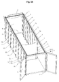
- the present invention relates to a lining for a bucket 30 dischargeable from the rear by tilting and a bucket, said packed, equipped with such a liner.
- It relates more particularly to a lining for a bucket which comprises a front face 31, a rear face 32 of unloading, two longitudinal faces 33 interconnecting the front faces 31 and rear 32 of said bucket and a bottom.
- the rear face 32 of unloading of the bucket can be a formed face a pivoting flap, pivotable about a horizontal axis disposed adjacent the upper edge of the flap.
- This rear face 32 unloading can still, as in the example shown, be formed of two doors opening to the French.
- the face of the top of the bucket is an open face to allow loading from above the bucket.
- This top face can be closed by means of a tarpaulin type blanket stored, in the wound state, in the open position of the face of the top.
- This face of the top of the bucket can be equipped with a hoop 34 interconnecting the longitudinal sides of the bucket.
- This bucket is generally equipped, under its bottom face, lifting means for tilting of the bucket rearward with a bottom inclined from a high point forward to a rear low point, so as to allow unloading by gravity of the load from the front to the back of the bucket.
- the insert insertable at least partially inside the bucket comprises at least one pocket 1, foldable, opening 6 loading from above.
- This pocket 1 has a bottom 1A and a peripheral wall 1B B bound to the bottom 1A.
- Said continuous or discontinuous peripheral side wall 1 B has at least two facing parts forming the sidewalls 2, 3 of said pocket and a portion connecting said parts facing each other and forming the so-called rear end face of the pocket.
- the portion of the pocket opposite the rear end face of the pocket forms the front end face 4 of the pocket.
- This front end face 5 may be an open face when the peripheral side wall 1b of the pocket is interrupted in this area.
- this front end face 4 of the bag is closable by the front face 31 of the bucket in the coupled state of the edges of the sidewalls and the bottom of the pocket used for the delimitation of said front end face 4 to the face 31 before the dumpster.
- This front end face 5 of the pocket may be at least partially closed as shown in FIG. Figure 2A , said front end face being shaped similarly to the rear end face of the pocket by a portion of the peripheral side wall 1 B of the pocket connecting the sidewalls with each other so that the front end faces and back of the pocket are formed by two parts facing the pocket.
- This pocket therefore has, in the unfolded state, a parallelepipedal general shape.
- the flanks 2, 3 of the bag are positionable opposite the longitudinal faces 33 of the bucket, while the end faces 4, 5 of the bag are positionable one, facing the front face of the bucket, the other, facing the rear face 32 of the bucket.
- the end face 5, referred to as the rear of the bag, positionable opposite or facing the rear face 32 of the unloading of the bucket, is provided with an opening 7 for unloading the contents of the bag 1.
- This opening 7 for unloading the contents of the bag is a closable opening whose closure means can affect a large number of shapes.
- This pocket is a flexible pouch.
- This pocket may be made of a waterproof material of the type chosen from the materials used in particular for the production of tarpaulins or blankets made of plastic.
- This pocket is dimensioned such that the height of the peripheral side wall of said pocket is preferably at least equal to the height of the longitudinal and end faces of the bucket.
- the loading opening of the bag is delimited at least by the free upper edges of the sidewalls 2, 3 and the rear end face of the bag.
- the pocket is a foldable pocket to allow the passage of said pocket of a folded state, called inactive configuration, in which it releases a portion of the volume of the bucket to allow a direct filling of the bucket, that is to say a loading of the bucket in a first type of loads intended for come into contact with the walls of the bucket, and an expanded state, called active configuration, in which it fills the interior volume of the bucket to allow an indirect filling of the bucket, that is to say a filling of the bucket via the pocket in a second type of load which may be identical to the first type of load, the second type of load being intended not to come into contact with the walls of the bucket may be in contact with the first type of load at during the phases of loading, transport and unloading of the load.
- inactive configuration in which it releases a portion of the volume of the bucket to allow a direct filling of the bucket, that is to say a loading of the bucket in a first type of loads intended for come into contact with the walls of the bucket
- active configuration in which it fills the interior volume
- the lining further comprises, for each flank 2; 3 of the pocket means 8; 9 guiding movement of said sidewall and means 10, 11 flank sliding coupling means to said means 8; 9 for the passage of the pocket 1 from an extended position of the sidewalls 2, 3 corresponding to an active configuration of greater bulk of the pocket in which the end faces 4, 5 are spaced apart from one of the other, that is to say the rear end face of the pocket is spaced from the front face of the bucket, to an inactive configuration of smaller size in which the flanks 2, 3 are folded and the faces 4, 5 end are brought closer to each other, that is to say, the rear end face of the pocket is close to the front face of the bucket.
- This passage from the active configuration of the pocket to the inactive configuration of the pocket takes place inside the bucket by bringing the rear end face of the pocket of the front end face of the pocket adjacent to it. the front of the bucket.
- the end faces 4, 5 of the pocket are positioned close to the front face of the bucket, the remaining free volume between the rear face of the bucket and the rear end face of the pocket is used as a volume. filling the bucket, while in active configuration, it is the volume of the pocket extending between front end face and back end face of the pocket that is used as filling volume.
- the means 8; 9 guiding a sidewall 2; 3 of the pocket are intended to take at least partially indirect support on the bucket, particularly on the top of the front and rear sides of the bucket.
- These means 8; 9 guiding a sidewall 2; 3 of the bucket comprise at least one element of the rail type 8A; 9A at which the upper part of said sidewall is coupled via members 10A; 11A rolling or sliding for sliding movement of the sidewall 2; 3 along said rail 8A; 9A.
- the coupling zones between the rolling or sliding members and the wall flank are arranged at intervals along the upper edge of each flank in the deployed position of said flank so that, in the folded state, the flank has a folded structure at ripples or folds in accordion.
- Each rail extends parallel to a longitudinal face of the bucket, generally at the upper edge of said face in the open position of the loading opening of the pocket.
- the rolling or sliding members are in turn formed, traditionally, by wheel or roller carriages.
- Each rail is thus provided with a longitudinal slot inside which a portion of each carriage, in particular the wheel or the roller of the carriage can slide, the other part of the carriage being coupled to a side of the pocket. It is also possible to equip the flanks of the pocket rings, able to be threaded along said rails.
- the lining comprises, for each side 2; 3 of the pocket, means 12; 13 for movable mounting moving means 8; 9 guiding the sidewall of the pocket in the direction of a ratment and a spacing means 9; 8 for guiding the other side of the pocket, for the passage of the opening 6 for loading the pocket from an open position to a closed position and vice versa.
- the close position of the means 8 for guiding one side of the pocket and the means 9 for guiding the other side of the pocket corresponds to the closed position of the opening 6 loading of the pocket and the position spaced from the means 8 for guiding one side of the pocket and the means 9 for guiding the other side of the pocket corresponds to the open position of the opening 6 for changing the pocket .
- the pocket is therefore a foldable pocket able to go from an inactive configuration corresponding to the folded state of the pocket to an active configuration corresponding to the unfolded state and vice versa by deployment and withdrawal of its flanks in the direction of a spacing and a combination of its end faces and an open position to a closed position and vice versa of its loading opening by bringing and spacing its flanks, in particular the upper edge of its flanks in active configuration.
- the means 12; 13, for the passage of the means 8; 9 guiding a sidewall 2; 3 of the pocket of a position spaced at a position close to the means 9; 8 guiding the other side 3; 2 of the pocket comprise at least moving drive means of said guide means.
- the liner comprises means 12, 13 through which said rails 8A, 9A are able to be mounted movable in the direction of a bringing together and spacing from one another for the passage of the opening 6 loading the pocket from an open position to a closed position and vice versa.
- the means, through which said rails 8A, 9A are adapted to be mounted movable in the direction of a bringing together and spacing from each other for the passage of the opening 6 of the loading of the pocket from an open position to a closed position and vice versa, comprise for each rail 8A; 9A at least means 12; 13 driving in displacement of said rail, these drive means in displacement of said rail comprising at least one rack whose at least one pinion 12A, 13A is carried by said rail 8A, 9A to move and whose part 12B, 13B rectilinear notched, adapted to mesh with the at least one pinion 12A, 13A, is positionable perpendicularly to said rail 8A, 9A.
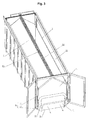
- the figures 1 and 3 illustrate the two extreme positions likely to be occupied by the rails 8A, 9A constituting the means for guiding the flanks 2, 3 of the pocket.
- flank 2 coupled to the rail 8A by means of rolling or friction members 10 and the flank 3 coupled to the rail 9A by means of rolling or friction members 11 are in the widest position to the figure 1 and in the closest approach position to the figure 3 .
- These rails therefore extend parallel to the upper edge of the sides of the pocket, in the active configuration of the pocket, and parallel to the longitudinal faces of the bucket and are movable in a direction transverse to said rails in the direction of a rimpedement and a gap.
- these rails move parallel to themselves in the direction of a rimpedement for closing the loading opening of the pocket and a spacing from one another for the opening of the opening loading the pocket.
- the close position of the rails constituting the guide means therefore corresponds to the closed position of the opening 6 of loading while the position separated from the rails, constituting the guide means, corresponds to the open position of the opening 6 unloading.
- the rails In the closed position of the unloading opening 6, the rails extend substantially parallel to the median longitudinal axis of the bucket and at this central longitudinal axis.
- each rail 8A; 9A is equipped at or near its free end, a pinion 12A, rotating 13A meshing with a piece 12B, 13B rectilinear notched disposed generally above and parallel to one of the front or rear faces of the dumpster.
- This piece 12B, 13B is coupled to the bucket coming for example on one of the front or rear faces of the bucket.
- Each rail 8A, 9A therefore comprises two gears, namely one at each of its ends.
- Each pinion engages a rectilinear piece notched to form a rack.
- the pinion of each rail adjoining the rear face of the bucket engages the notched straight piece disposed above the rear face of the bucket, while the pinion of each rail adjoining the front face of the bucket bucket engages with the notched rectilinear piece disposed above the front face of the bucket.
- the pinions equipping the same rail are interconnected by a motion transmission member, such as a rod, so as to allow during the rotational drive of one of the pinions, the rotational drive of the other pinion.
- This rod is preferably housed inside the rail in a longitudinal through cavity or longitudinal groove of said rail as shown in FIG. figure 11 .
- This longitudinal cavity is preferably formed at the top of said rail.
- This drive in rotation of the gears meshing with a rectilinear piece causes a displacement of the rail parallel to itself in the sense of a ratment or a distance from the other rail.
- This rotation drive sprockets can operate using a crank 23 as illustrated by the figure 6 .
- each pinion may be equipped at its center with a square adapted to engage by interlocking with the end of the crank.
- the notched rectilinear part of the rack and its pinion are surmounted by a cover to at least partially mask said elements. It is the same for the guide rails.
- the motion transmission member is housed inside the rail in a cavity or longitudinal groove of said rail open at each of its ends.
- This rail preferably comprises a second longitudinally slotted longitudinal cavity, also called a slot inside which are housed the sliding coupling means of the sidewall to the guide means.
- This second cavity is disposed at the base of the rail.
- the drive means for moving the guide means could be replaced by slides along which the rails would move.
- the slides would have a position similar to that of the rectilinear pieces notched in the case of a rack.
- the risk is that the rail, because of its length, does not move properly parallel to itself.
- the presence of a pinion meshing with a rectilinear piece at each end of the rail avoids this pitfall.
- the lining comprises means 14 which can be activated / deactivated to keep the means 8 for guiding one side 2 of the pocket in the close position and means 9 for guiding the other side 3 of the pocket.
- these holding means 14 are here formed by a jumper positionable on the outer face of the front face of the bucket, the rider being adapted to be driven by a rising and falling movement and coming in the upper position to grip the rods each carrying a pair of gears of a rail. In this high position, this jumper prevents a spacing of said rails.
- the bucket is equipped with a hoop 34 interconnecting the longitudinal sides of the bucket.
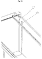
- This arch 34 is provided, in its central zone, on its underside with resilient lugs 35 engageable with slots 36 formed on the top of each rail.
- the hoop has two pairs of legs, each pair of legs being adapted to engage with a pair of lights carried by a rail.
- the tab 35/36 light cooperation ensures the maintenance of the rails in close position.
- the activatable / deactivatable means 14 for holding the means 8 for guiding one side of the pocket and the means 9 for guiding the other side 3 of the pocket in the close position are thus formed of male member (s).
- the lug type and female member (s) preferably of light kind able to be worn either one or by the guide means, the other or others by a stationary part of the bucket , these male and female members being adapted to engage generally by elastic deformation when the guide means occupy a position corresponding to the closed position of the loading opening.
- the liner comprises means 15 for activating / deactivating the tension of the sidewalls 2, 3 of the pocket in order to maintain the stretched state of said sidewalls 2, 3 in the active configuration of greater bulk of the pocket, in which the end faces 4, 5 are spaced from each other.
- these flank tensioning means can affect a large number of shapes.
- these tensioning means comprise two parallel uprights 21 each arranged along a vertical edge of the rear end face of the pocket.
- Each upright 21 is adapted, in the active configuration of the pocket, to engage interlocking with a male member 22 of the genus pad, or a female member of the sleeve type, disposed in the bottom face of the bucket, and projecting under the bottom of the bucket, to be rotated about its longitudinal axis by means for example of a lever disposed under said bottom so as to allow by rotation of the uprights 21 a tension of the sides of the pocket.
- These amounts 21 are disengageable from the bottom forming face of the bucket for the passage of the pocket of the active configuration to the inactive configuration.
- a similar tensioning system can be provided at the front of the bucket, this tensioning system being operable no longer by the bottom but by the top of the bucket using a crank as shown in FIG. figure 7 .
- the amounts coupled to the end face of the bag are only rotatable.
- each side of the pocket is equipped with a sidewall tensioning cable, this cable being at one of its ends fixed to the first carriage of the pocket and at its other end at a stationary point pocket or bucket.
- This first drive carriage is the one positioned, among the set of carriages, closest to the rear end face of the pocket.
- the unloading opening 7 of the contents of the bag is formed in the lower half of the rear end face 5 of the bag.
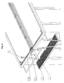
- the lower edge of the unloading opening 7 which extends between the two sides 2, 3 of the bag is provided with a flap 16 that can be positioned to be applied against the external surface of the rear end face 5 of the bag. allow the closure of said opening 7 unloading.
- This flap 16 is retained applied against said outer surface by means of connecting members to the rear end face 5 such as tensioners as shown in FIG. figure 10 .
- this flap In the extended position, that is to say away from the rear end face of the pocket, this flap covers the rear free edge of the bottom of the bucket to prevent contact of the material exiting the pocket with the walls of the bucket.
- the passage of the flap from the applied position corresponding to the closed position of the unloading opening to the extended position corresponding to the open position of said unloading opening is effected by simply detaching the tensioning type connecting members from the unloading opening. the rear end face 5 of the pocket.
- the rear end face 5 of the bag is interrupted in the vicinity of its connection zone to the bottom 1A of the pocket, over at least part of its width corresponding to the distance between the sides 2, 3 of the pocket, to form the opening 7 unloading the contents of the pocket.
- the rear end face 5 of the bag is, in the area adjoining the discharge opening 7, provided, at its lower corners, in the zone of connection to the sidewalls 2, 3 of the pocket, of bellows 17, adapted to facilitate the opening of the opening 7 unloading the contents of the pocket.
- the pad further comprises at least one flap 18 for at least partial isolation or wrapping of the pocket 1, in the erected state. and in the active position to compartmentalize the bucket transversely, and means 19, 20 activatable / deactivatable holding the flap 18, in the erected state, in the active position.
- flap 18 for at least partial isolation or wrapping of the pocket 1, in the erected state. and in the active position to compartmentalize the bucket transversely, and means 19, 20 activatable / deactivatable holding the flap 18, in the erected state, in the active position.
- the shutter 18 is movably mounted between an active position in which it extends substantially parallel to the front face 31 of the bucket and defines, with said face, a housing of the pocket space inactive configuration, in the activated state said holding means 19, 20, and an inactive flat position in which it is able to extend under the bottom 1A of the pocket, preferably in the vicinity of the front end face 4 of the pocket, to the deactivated state of said holding means 19, 20.
- These holding means 19, 20 are for example formed by two angles or profiles 19 each positioned vertically along a longitudinal face of the bucket to form end stops of the vertical edges of the flap or uprights equipping the vertical edges the flap in the upright position of said flap and by a latch 20 or screws arranged (s) on the side of the flap facing the rear face of the bucket to maintain the flap upright.
- a seal may be provided at the angles or profiles, said seal being compressed by the flap in the upwardly active state of said flap.
- the flat position of the flap is more particularly visible in the figure 1 .
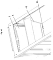
- the standing position of the component is represented in Figures 4A and 4B .
- the flap 18 is connected to the bottom of the bucket by a hinge type pivot connection whose design allows the realization of a connection as tight as possible between the lower edge of the shutter and bottom of the bucket in the erected state of the shutter.
- this shutter thus compartmentally transverses the bucket and separates the initial filling volume of the bucket into two volumes, one extending between the front face and the shutter, this volume containing the pocket in the inactive configuration of the latter, the other extending between the flap and rear face of the bucket, this volume corresponding to the loading volume of the bucket when the pocket is not used.
- the flap 18 may be pivotably mounted along a vertical axis extending along a longitudinal wall of the bucket for the passage of the flap of an inactive position in which it extends along a longitudinal wall of the bucket substantially parallel to the latter at an active position in which it compartmentally transverse the interior volume of the bucket.
- the method of loading / unloading such a bucket therefore comprises at least two series of loading / unloading steps selectively activatable.
- the pinions are adapted to meshing engagement with said rectilinear pieces notched on said parts, the pinions pre-equipping the rails to which the sides of the pocket are slidably coupled. It is also necessary, if necessary, to equip the bucket with the stationary portion of the means for tensioning the flanks of the pouch, this stationary portion being formed by the male members of the gender of the stud or female type of sheath described above. It is also appropriate to equip the bucket means 14 activatable / deactivatable maintaining in the close position of the means 8 and 9 for guiding a side of the pocket. It may also be necessary to equip the bucket of the flap 18 and the means 19, 20 for holding the flap 18 of the liner in the erected position. It is assumed that this trim that pre-equips the bucket has a pocket inactive configuration.
- Said pocket being, in an inactive configuration, in which the rear end faces of the pocket is close to the front face of the bucket and provides an empty space for loading with the rear face of the bucket, one of the series of steps of loading / unloading, said series of steps of loading / unloading the bag, comprises at least one phase of separation of the rear end face of the pocket of the front face of the bucket to bring said pocket in the active configuration of greater size of the pocket, a filling phase of the pocket by its loading opening, a phase of emptying the pocket by its unloading opening and, by the rear face of the bucket, a phase of Folding the pocket by bringing the rear end face of the pocket of the front face of the pocket closer to supplying the pocket in the inactive configuration of smaller size.
- said method comprises at least one filling phase of the space left free between the pocket and the rear face of the bucket and unloading phase of the bucket by the rear face of the bucket.
- the unloading phase requires the opening of the doors forming the rear face of the bucket and the tilting of said bucket.
- said method further comprises, if necessary before the series of loading / unloading steps of the ladle, a phase of bringing the flap into the inactive position, for example by flap of the flap against the bottom of the bucket prior to the separation phase of the rear end face of the front face of the bucket of the pocket to bring the pocket in the active configuration and after the series of steps of loading / unloading the pocket, a step of bringing the shutter into the active position for example by straightening the flap at the end of the folding phase of the pocket by bringing the rear end face of said pocket of the front face of the dumpster.
- said method may comprise, in the series of loading / unloading steps of the bag, a phase of tension of the flanks of the bag at the end of the separation phase of the rear end face of the bag. pocket of the front face of the bucket bringing the pocket in active configuration of larger size of the pocket, and prior to the filling phase of said pocket.
- Said method may further comprise, in the series of loading / unloading steps of the bag, a closing phase of the loading opening after the filling phase of the bag and then a phase of opening of the loading opening before the emptying phase of the ladle, these closing and opening phases taking place respectively by bringing the guiding means of the flanks of the pocket closer to and away from said guiding means.
Landscapes
- Engineering & Computer Science (AREA)
- Mechanical Engineering (AREA)
- Purses, Travelling Bags, Baskets, Or Suitcases (AREA)
- Chain Conveyers (AREA)
Claims (19)
- Auskleidung für einen nach hinten durch Kippen entladbaren Aufbau (30), wobei die Auskleidung mindestens eine Tasche (1) mit Beladeöffnung (6) von oben umfasst, die in den Aufbau einsetzbar ist, wobei die Tasche (1) einen Boden (1A) und eine mit dem Boden (1A) verbundene seitliche Umfangswand (1 B) aufweist, wobei die seitliche Umfangswand (1 B) mindestens zwei gegenüberliegende Teile aufweist, die die Flanken (2, 3) der Tasche bilden und mindestens einen Teil, der die einander gegenüberliegenden Teile verbindet und eine (5) der Endseiten (4, 5) der Tasche bildet, nämlich die hintere Endseite (5) der Tasche, wobei die Flanken (2, 3) und die hintere Endseite (5) der Tasche jeweils, was die einen (2, 3) betrifft, gegenüber den Längsseiten (33) des Aufbaus, was die andere (5) betrifft, gegenüber der hinteren Seite (32) des Aufbaus positionierbar sind"
dadurch gekennzeichnet, dass die Tasche (1) eine faltbare Tasche ist, dass die hintere Endseite (5) der Tasche, die gegenüber der hinteren Entladeseite (32) des Aufbaus positionierbar ist, mit einer Entladeöffnung (7) des Inhalts der Tasche (1) ausgestattet ist und dass die Auskleidung ferner für jede Flanke (2; 3) der Tasche Verlagerungsführungsmittel (8; 9) der Flanke und Gleitkopplungsmittel (10; 11) der Flanke an den Führungsmitteln (8; 9) für den Übergang der Tasche (1) von einer aktiven Konfiguration größeren Platzbedarfs der Tasche, in der die Flanken (2, 3) entfaltet sind, und einer inaktiven Konfiguration geringeren Platzbedarfs, in der die Flanken (2, 3) gefaltet sind, aufweist. - Auskleidung nach Anspruch 1,
dadurch gekennzeichnet, dass sie für jede Flanke (2; 3) der Tasche Mittel (12; 13) für eine bewegliche Verlagerungsmontage der Führungsmittel (8; 9) der Flanke der Tasche in Richtung einer Annäherung und einer Entfernung der Führungsmittel (9; 8) der anderen Flanke der Tasche im Hinblick auf den Übergang der Beladeöffnung (6) der Tasche von einer geöffneten Position in eine geschlossene Position und umgekehrt aufweist. - Auskleidung nach Anspruch 2,
dadurch gekennzeichnet, dass die Mittel (12; 13) für den Übergang der Führungsmittel (8; 9) einer Flanke (2; 3) der Tasche von einer entfernten Position in eine angenäherte Position der Führungsmittel (9; 8) der anderen Flanke (3; 2) der Tasche mindestens Verlagerungsantriebsmittel der Führungsmittel umfassen. - Auskleidung nach einem der Ansprüche 1 bis 3,
dadurch gekennzeichnet, dass die Führungsmittel (8; 9) einer Flanke (2; 3) der Tasche mindestens ein Element der Art Schiene (8A; 9A) umfassen, an die der obere Teil der Flanke mit Hilfe von Roll- oder Gleitorganen (10A; 11A) für eine gleitende Verlagerung der Flanke (2; 3) entlang der Schiene (8A; 9A) umfassen. - Auskleidung nach Anspruch 4,
dadurch gekennzeichnet, dass sie Mittel (12, 13) aufweist, mit deren Hilfe die Schienen (8A, 9A) in Richtung einer Annäherung und einer Entfernung zueinander für den Übergang der Beladeöffnung (6) der Tasche von einer geöffneten Position in eine geschlossene Position und umgekehrt beweglich montierbar sind. - Auskleidung nach Anspruch 5,
dadurch gekennzeichnet, dass die Mittel, mit deren Hilfe die Schienen (8A, 9A) in Richtung einer Annäherung und einer Entfernung voneinander für den Übergang der Beladeöffnung (6) der Tasche von einer geöffneten Position in eine geschlossene Position und umgekehrt beweglich montierbar sind, für jede Schiene (8A; 9A) mindestens Verlagerungsantriebsmittel (12; 13) der Schiene umfassen, wobei diese Verlagerungsantriebsmittel der Schiene mindestens eine Zahnstange aufweisen, deren mindestens ein Zahnrad (12A; 13A) von der zu verlagernden Schiene (8A; 9A) getragen wird, und deren gerades Rastteil (12B; 13B), das imstande ist, mit dem mindestens einen Zahnrad (12A; 13A) zu rasten, lotrecht zur Schiene (8A; 9A) positionierbar ist. - Auskleidung nach einem der Ansprüche 2 oder 3,
dadurch gekennzeichnet, dass sie Haltemittel (14) aufweist, die in angenäherter Position der Führungsmittel (8) einer Flanke (2) der Tasche und der Führungsmittel (9) der anderen Flanke (3) der Tasche aktivierbar/deaktivierbar sind. - Auskleidung nach einem der Ansprüche 1 bis 7,
dadurch gekennzeichnet, dass die Auskleidung aktivierbare/deaktivierbare Spannungsmittel (15) der Flanken (2, 3) der Tasche im Hinblick auf einen gespannten Zustand der Flanken (2, 3) in aktiver Konfiguration größeren Platzbedarfs der Tasche aufweist. - Auskleidung nach einem der Ansprüche 1 bis 8,
dadurch gekennzeichnet, dass die Entladeöffnung (7) des Inhalts der Tasche eine verschließbare Öffnung ist. - Auskleidung nach einem der Ansprüche 1 bis 9,
dadurch gekennzeichnet, dass der untere Rand der Entladeöffnung (7), der sich zwischen den zwei Flanken (2, 3) der Tasche erstreckt, mit einer Klappe (16) ausgestattet ist, die anliegend an der Außenfläche der hinteren Endseite (5) der Tasche positionierbar ist, um den Verschluss der Entladeöffnung (7) zu erlauben. - Auskleidung nach einem der Ansprüche 1 bis 10,
dadurch gekennzeichnet, dass die hintere Endseite (5) der Tasche in der Nähe ihrer Anschlusszone an den Boden (1A) der Tasche über mindestens einen Teil ihrer Breite unterbrochen ist, der dem Abstand zwischen den Flanken (2, 3) der Tasche entspricht, um die Entladeöffnung (7) des Inhalts der Tasche zu bilden. - Auskleidung nach einem der Ansprüche 1 bis 11,
dadurch gekennzeichnet, dass die vordere Endseite (4) der Tasche (1), die der hinteren Endseite (5) der Tasche gegenüberliegt, in Form einer verschließbaren offenen Seite realisiert ist, die imstande ist, von der Vorderseite (31) des Aufbaus verschlossen zu sein, wenn die Tasche in den Aufbau eingesetzt ist. - Auskleidung nach einem der Ansprüche 1 bis 12,
dadurch gekennzeichnet, dass sie ferner mindestens einen Isolierflügel (18) der Tasche (1) aufweist, der imstande ist, zwischen zwei Positionen, einer aktiven, in der der Flügel (18) aufgerichtet ist und von außen die hintere Endseite (5) der Tasche doubliert, und einer andern inaktiven, in der er den Zugang zur hinteren Endseite (5) der Tasche freigibt, beweglich montiert zu sein. - Auskleidung nach Anspruch 13,
dadurch gekennzeichnet, dass sie ferner aktivierbare/deaktivierbare Haltemittel (19, 20) des Flügels (18) in aufgerichteter Position aufweist, um den Übergang des Flügels (18) aus einer aufgerichteten Position, in der er im aktivierten Zustand der Haltemittel (19, 20) von außen die hinteren Endseite (5) doubliert, in eine flache Position, in der er imstande ist, sich im deaktivierten Zustand der Haltemittel (19, 20) unter dem Boden (1A) der Tasche zu erstrecken, vorzugsweise in der Nähe der vorderen Endseite (4) der Tasche, die der hinteren Endseite (5) der Tasche gegenüberliegt, zu erlauben. - Nach hinten durch Kippen entladbarer Aufbau (30), wobei der Aufbau (30) einen Boden, eine hintere Seite (32), Längsseiten (33) und eine Vorderseite (31) umfasst und mit einer Auskleidung ausgestattet ist, die mindestens teilweise in den Aufbau (30) einsetzbar ist, wobei die Auskleidung mindestens eine Tasche (1) mit Beladeöffnung (6) von oben umfasst, wobei die Tasche (1) einen Boden (1A) und eine mit dem Boden (1A) verbundene seitliche Umfangswand (1 B) aufweist, wobei die seitliche Umfangswand (1 B) mindestens zwei gegenüberliegende Teile aufweist, die die Flanken (2, 3) der Tasche bilden und mindestens einen Teil, der die einander gegenüberliegenden Teile verbindet und eine (5) der Endseiten (4, 5) der Tasche bildet, nämlich die hintere Endseite (5) der Tasche, wobei die Flanken (2, 3) und die hintere Endseite (5) der Tasche jeweils, was die einen (2, 3) betrifft, gegenüber den Längsseiten (33) des Aufbaus, was die andere (5) betrifft, gegenüber der hinteren Seite (32) des Aufbaus positionierbar sind,
dadurch gekennzeichnet, dass die hintere Endseite (5) der Tasche, die gegenüber der hinteren Entladeseite (32) des Aufbaus positionierbar ist, mit einer Entladeöffnung (7) des Inhalts der Tasche (1) ausgestattet ist
und dass die Tasche (1) eine faltbare Tasche ist, die im in den Aufbau eingesetzten Zustand ihre beweglich montierte hintere Endseite in Richtung einer Annäherung und einer Entfernung von der Vorderseite des Aufbaus gemäß einer Richtung etwa parallel zur Längsachse des Aufbaus zwischen einer aktiven Konfiguration der Tasche, die auch als entfalteter Zustand der Tasche bezeichnet wird, der dem entfernten Zustand der Seiten und der Entfaltung der Flanken entspricht, und einer inaktiven Konfiguration der Tasche, die auch als gefalteter Zustand der Tasche bezeichnet wird, der dem angenäherten Zustand der Seiten der Faltung der Flanken entspricht, präsentiert. - Aufbau nach Anspruch 15,
dadurch gekennzeichnet, dass die Flanken der Tasche in aktiver Konfiguration der Tasche mindestens teilweise in Richtung einer Annäherung und einer Entfernung voneinander gemäß einer Querrichtung vorzugsweise orthogonal zur Längsachse des Aufbaus zwischen einer geschlossenen Position der Beladeöffnung der Tasche, die dem angenäherten Zustand der Flanken, insbesondere der oberen freien Ränder der Flanken, entspricht, und einer geöffneten Position der Beladeöffnung der Tasche, die dem entfernten Zustand der Flanken, insbesondere der oberen freien Ränder der Flanken, entspricht, beweglich montiert sind. - Aufbau nach einem der Ansprüche 15 oder 16,
dadurch gekennzeichnet, dass die Auskleidung noch mindestens einen Isolierflügel der Tasche aufweist, der im aufgerichteten Zustand in aktiver Position den Aufbau quer in einen ersten Raum, der zwischen der vorderen Seite des Aufbaus und dem Flügel angeordnet ist und die Tasche im gefalteten Zustand in inaktiver Konfiguration aufnimmt, und in einem zweiten Raum, der zwischen dem Flügel und der hinteren Seite des Aufbaus angeordnet ist und in dem eine Last transportiert werden kann, unterteilt. - Nach hinten entladbarer Aufbau (30) nach einem der Ansprüche 15 bis 17,
dadurch gekennzeichnet, dass die Auskleidung des Aufbaus einem der Ansprüche 2 bis 12 entspricht. - Belade-/Entladeverfahren eines Aufbaus nach einem der Ansprüche 16 bis 18, wobei die faltbare Tasche der Auskleidung, die imstande ist, von einer aktiven Konfiguration größeren Platzbedarfs der Tasche, bei die die Flanken entfaltet sind, in eine inaktive Konfiguration geringeren Platzbedarfs, in der die Flanken gefaltet sind, zu wechseln, in inaktiver Konfiguration ist mit der hinteren Endseite der Tasche angenähert an die vordere Seite des Aufbaus, wobei ein freier Laderaum mit der hinteren Seite des Aufbaus ausgebildet wird,
dadurch gekennzeichnet, dass das Verfahren mindestens zwei selektiv aktivierbare Belade-/Entladeschrittserien umfasst und dass das Verfahren während einer der Schrittserien, als Belade-/Entladeschrittserie der Tasche bezeichnet, mindestens eine Entfernungsphase der hinteren Endseite der Tasche von der vorderen Seite des Aufbaus, bis die Tasche in die aktive Konfiguration größeren Platzbedarfs der Tasche geführt ist, eine Füllphase der Tasche durch ihre Beladeöffnung (6), eine Entleerungsphase der Tasche durch ihre Entladeöffnung (7), eine Faltphase der Tasche durch Annäherung der hinteren Endseite der Tasche an die vordere Seite des Aufbaus, bis die Tasche in die inaktive Konfiguration kleineren Platzbedarfs geführt ist, umfasst, und dass während der anderen Belade-/Entladeschrittserie, als Belade-/Entladeschrittserien des Aufbaus bezeichnet, das Verfahren eine Füllphase des zwischen der Tasche und der hinteren Seite des Aufbaus freigelassenen Raums und eine Entladephase des Aufbaus über die hinteren Seite des Aufbaus umfasst.
Applications Claiming Priority (3)
| Application Number | Priority Date | Filing Date | Title |
|---|---|---|---|
| FR1150746A FR2970917B1 (fr) | 2011-02-01 | 2011-02-01 | Garniture pour benne dechargeable par l'arriere, benne equipee d'une telle garniture et son procede de chargement/dechargement |
| FR1153364A FR2970918B1 (fr) | 2011-02-01 | 2011-04-19 | Garniture pour benne dechargeable par l'arriere, benne equipee d'une telle garniture et son procede de chargement/dechargement |
| FR1159770A FR2970919B1 (fr) | 2011-02-01 | 2011-10-27 | Garniture pour benne dechargeable par l'arriere, benne equipee d'une telle garniture et son procede de chargement/dechargement |
Publications (2)
| Publication Number | Publication Date |
|---|---|
| EP2481639A1 EP2481639A1 (de) | 2012-08-01 |
| EP2481639B1 true EP2481639B1 (de) | 2013-12-25 |
Family
ID=45478254
Family Applications (1)
| Application Number | Title | Priority Date | Filing Date |
|---|---|---|---|
| EP20120152232 Not-in-force EP2481639B1 (de) | 2011-02-01 | 2012-01-24 | Auskleidung für Heckkipplastwagen, mit einer solchen Auskleidung ausgestatteter Heckkipplastwagen sowie sein Belade- und Entladeverfahren |
Country Status (2)
| Country | Link |
|---|---|
| EP (1) | EP2481639B1 (de) |
| FR (1) | FR2970919B1 (de) |
Families Citing this family (1)
| Publication number | Priority date | Publication date | Assignee | Title |
|---|---|---|---|---|
| CN116177062B (zh) * | 2023-04-27 | 2023-11-28 | 太仓中集特种物流装备有限公司 | 一种散货集装箱 |
Family Cites Families (5)
| Publication number | Priority date | Publication date | Assignee | Title |
|---|---|---|---|---|
| US6076693A (en) * | 1996-12-13 | 2000-06-20 | Wasteco Manufacturing | Molded container assembly for transporting bulk materials |
| US5803531A (en) * | 1997-05-21 | 1998-09-08 | Nielsen; Jack T. | Liner system for a hauling compartment |
| DE10064626B4 (de) * | 2000-12-22 | 2004-07-15 | Tom Sperling | Schutzverkleidung für einen Laderaum eines Kraftfahrzeuges |
| CA2511691A1 (en) * | 2004-07-08 | 2006-01-08 | E.A.I. Technologies | Mobile filtration system and method |
| US7943051B2 (en) * | 2009-02-18 | 2011-05-17 | David Douglas Dieziger | Portable settling and dewatering tank |
-
2011
- 2011-10-27 FR FR1159770A patent/FR2970919B1/fr not_active Expired - Fee Related
-
2012
- 2012-01-24 EP EP20120152232 patent/EP2481639B1/de not_active Not-in-force
Also Published As
| Publication number | Publication date |
|---|---|
| EP2481639A1 (de) | 2012-08-01 |
| FR2970919A1 (fr) | 2012-08-03 |
| FR2970919B1 (fr) | 2014-08-01 |
Similar Documents
| Publication | Publication Date | Title |
|---|---|---|
| CA2676793C (fr) | Conteneur deployable de bouteilles ou similaires | |
| EP3074310B1 (de) | Verfahren zum laden eines zu füllenden flexiblen 3d-beutels, system zum laden und speichern dieses flexiblen beutels und zugehörige stützvorrichtung | |
| FR2785160A1 (fr) | Structure pour boite a cosmetiques et cette boite | |
| EP2888175B1 (de) | Zusammenklappbarer metallischer behälter | |
| EP2481639B1 (de) | Auskleidung für Heckkipplastwagen, mit einer solchen Auskleidung ausgestatteter Heckkipplastwagen sowie sein Belade- und Entladeverfahren | |
| FR2859358A1 (fr) | Ensemble formant bagage a roulettes | |
| FR2972179A1 (fr) | Conteneur repliable equipe d'un amenagement specifique a poches repliable independamment | |
| FR2970918A1 (fr) | Garniture pour benne dechargeable par l'arriere, benne equipee d'une telle garniture et son procede de chargement/dechargement | |
| FR2837806A1 (fr) | Toit a ouverture du type accordeon pour conteneur du type benne et conteneur ainsi equipe | |
| CA1158278A (fr) | Amenagement interieur de vehicule tel que caravane pliante | |
| EP1775160B1 (de) | Verdeckaufbau für eine Fläche, insbesondere eine Ladefläche | |
| FR2922733A1 (fr) | Contenant a roulettes, notamment valise | |
| FR2687133A1 (fr) | Conteneur a dechets equipe d'une charniere perfectionnee. | |
| EP1528012B1 (de) | Frachtbehälter für Luftfracht. | |
| EP1512580B1 (de) | Gepäckabdeckung | |
| BE1006052A3 (fr) | Sac. | |
| FR2795709A1 (fr) | Module de stockage d'articles a elements de reception suspendus | |
| FR2733727A1 (fr) | Vehicule utilitaire comportant un bati de couverture avec un rancher mobile | |
| FR2937592A1 (fr) | Module arriere transformable pour vehicule automobile et vehicule automobile associe | |
| FR3025154A1 (fr) | Element de rangement mobile muni d'un double mecanisme dispose sous le pavillon d'un vehicule | |
| FR3025155A1 (fr) | Element de rangement a volume variable installe sous le pavillon d'un vehicule | |
| FR2736891A3 (fr) | Conteneur de transport a usage multiple | |
| FR3146632A1 (fr) | véhicule doté d’un espace de rangement pour des équipements fonctionnels portatifs | |
| FR3023756A1 (fr) | Element de rangement mobile muni d'une cinematique integre sous le pavillon d'un vehicule | |
| WO2007045743A1 (fr) | Bagage pliant |
Legal Events
| Date | Code | Title | Description |
|---|---|---|---|
| PUAI | Public reference made under article 153(3) epc to a published international application that has entered the european phase |
Free format text: ORIGINAL CODE: 0009012 |
|
| AK | Designated contracting states |
Kind code of ref document: A1 Designated state(s): AL AT BE BG CH CY CZ DE DK EE ES FI FR GB GR HR HU IE IS IT LI LT LU LV MC MK MT NL NO PL PT RO RS SE SI SK SM TR |
|
| AX | Request for extension of the european patent |
Extension state: BA ME |
|
| 17P | Request for examination filed |
Effective date: 20121227 |
|
| GRAP | Despatch of communication of intention to grant a patent |
Free format text: ORIGINAL CODE: EPIDOSNIGR1 |
|
| RIC1 | Information provided on ipc code assigned before grant |
Ipc: B60R 13/01 20060101AFI20130815BHEP |
|
| INTG | Intention to grant announced |
Effective date: 20130904 |
|
| GRAS | Grant fee paid |
Free format text: ORIGINAL CODE: EPIDOSNIGR3 |
|
| GRAA | (expected) grant |
Free format text: ORIGINAL CODE: 0009210 |
|
| AK | Designated contracting states |
Kind code of ref document: B1 Designated state(s): AL AT BE BG CH CY CZ DE DK EE ES FI FR GB GR HR HU IE IS IT LI LT LU LV MC MK MT NL NO PL PT RO RS SE SI SK SM TR |
|
| REG | Reference to a national code |
Ref country code: GB Ref legal event code: FG4D Free format text: NOT ENGLISH |
|
| REG | Reference to a national code |
Ref country code: CH Ref legal event code: EP |
|
| REG | Reference to a national code |
Ref country code: AT Ref legal event code: REF Ref document number: 646421 Country of ref document: AT Kind code of ref document: T Effective date: 20140115 |
|
| REG | Reference to a national code |
Ref country code: IE Ref legal event code: FG4D Free format text: LANGUAGE OF EP DOCUMENT: FRENCH |
|
| REG | Reference to a national code |
Ref country code: DE Ref legal event code: R096 Ref document number: 602012000686 Country of ref document: DE Effective date: 20140213 |
|
| REG | Reference to a national code |
Ref country code: NL Ref legal event code: T3 |
|
| REG | Reference to a national code |
Ref country code: ES Ref legal event code: FG2A Ref document number: 2453898 Country of ref document: ES Kind code of ref document: T3 Effective date: 20140408 |
|
| PG25 | Lapsed in a contracting state [announced via postgrant information from national office to epo] |
Ref country code: SE Free format text: LAPSE BECAUSE OF FAILURE TO SUBMIT A TRANSLATION OF THE DESCRIPTION OR TO PAY THE FEE WITHIN THE PRESCRIBED TIME-LIMIT Effective date: 20131225 Ref country code: FI Free format text: LAPSE BECAUSE OF FAILURE TO SUBMIT A TRANSLATION OF THE DESCRIPTION OR TO PAY THE FEE WITHIN THE PRESCRIBED TIME-LIMIT Effective date: 20131225 Ref country code: NO Free format text: LAPSE BECAUSE OF FAILURE TO SUBMIT A TRANSLATION OF THE DESCRIPTION OR TO PAY THE FEE WITHIN THE PRESCRIBED TIME-LIMIT Effective date: 20140325 Ref country code: LT Free format text: LAPSE BECAUSE OF FAILURE TO SUBMIT A TRANSLATION OF THE DESCRIPTION OR TO PAY THE FEE WITHIN THE PRESCRIBED TIME-LIMIT Effective date: 20131225 Ref country code: HR Free format text: LAPSE BECAUSE OF FAILURE TO SUBMIT A TRANSLATION OF THE DESCRIPTION OR TO PAY THE FEE WITHIN THE PRESCRIBED TIME-LIMIT Effective date: 20131225 |
|
| REG | Reference to a national code |
Ref country code: AT Ref legal event code: MK05 Ref document number: 646421 Country of ref document: AT Kind code of ref document: T Effective date: 20131225 |
|
| REG | Reference to a national code |
Ref country code: LT Ref legal event code: MG4D |
|
| PG25 | Lapsed in a contracting state [announced via postgrant information from national office to epo] |
Ref country code: RS Free format text: LAPSE BECAUSE OF FAILURE TO SUBMIT A TRANSLATION OF THE DESCRIPTION OR TO PAY THE FEE WITHIN THE PRESCRIBED TIME-LIMIT Effective date: 20131225 Ref country code: LV Free format text: LAPSE BECAUSE OF FAILURE TO SUBMIT A TRANSLATION OF THE DESCRIPTION OR TO PAY THE FEE WITHIN THE PRESCRIBED TIME-LIMIT Effective date: 20131225 |
|
| PG25 | Lapsed in a contracting state [announced via postgrant information from national office to epo] |
Ref country code: EE Free format text: LAPSE BECAUSE OF FAILURE TO SUBMIT A TRANSLATION OF THE DESCRIPTION OR TO PAY THE FEE WITHIN THE PRESCRIBED TIME-LIMIT Effective date: 20131225 Ref country code: IS Free format text: LAPSE BECAUSE OF FAILURE TO SUBMIT A TRANSLATION OF THE DESCRIPTION OR TO PAY THE FEE WITHIN THE PRESCRIBED TIME-LIMIT Effective date: 20140425 |
|
| PG25 | Lapsed in a contracting state [announced via postgrant information from national office to epo] |
Ref country code: RO Free format text: LAPSE BECAUSE OF FAILURE TO SUBMIT A TRANSLATION OF THE DESCRIPTION OR TO PAY THE FEE WITHIN THE PRESCRIBED TIME-LIMIT Effective date: 20131225 Ref country code: PT Free format text: LAPSE BECAUSE OF FAILURE TO SUBMIT A TRANSLATION OF THE DESCRIPTION OR TO PAY THE FEE WITHIN THE PRESCRIBED TIME-LIMIT Effective date: 20140428 Ref country code: LU Free format text: LAPSE BECAUSE OF FAILURE TO SUBMIT A TRANSLATION OF THE DESCRIPTION OR TO PAY THE FEE WITHIN THE PRESCRIBED TIME-LIMIT Effective date: 20140124 Ref country code: SK Free format text: LAPSE BECAUSE OF FAILURE TO SUBMIT A TRANSLATION OF THE DESCRIPTION OR TO PAY THE FEE WITHIN THE PRESCRIBED TIME-LIMIT Effective date: 20131225 Ref country code: AT Free format text: LAPSE BECAUSE OF FAILURE TO SUBMIT A TRANSLATION OF THE DESCRIPTION OR TO PAY THE FEE WITHIN THE PRESCRIBED TIME-LIMIT Effective date: 20131225 Ref country code: CY Free format text: LAPSE BECAUSE OF FAILURE TO SUBMIT A TRANSLATION OF THE DESCRIPTION OR TO PAY THE FEE WITHIN THE PRESCRIBED TIME-LIMIT Effective date: 20131225 Ref country code: CZ Free format text: LAPSE BECAUSE OF FAILURE TO SUBMIT A TRANSLATION OF THE DESCRIPTION OR TO PAY THE FEE WITHIN THE PRESCRIBED TIME-LIMIT Effective date: 20131225 |
|
| REG | Reference to a national code |
Ref country code: DE Ref legal event code: R097 Ref document number: 602012000686 Country of ref document: DE |
|
| PG25 | Lapsed in a contracting state [announced via postgrant information from national office to epo] |
Ref country code: MC Free format text: LAPSE BECAUSE OF FAILURE TO SUBMIT A TRANSLATION OF THE DESCRIPTION OR TO PAY THE FEE WITHIN THE PRESCRIBED TIME-LIMIT Effective date: 20131225 |
|
| PG25 | Lapsed in a contracting state [announced via postgrant information from national office to epo] |
Ref country code: DK Free format text: LAPSE BECAUSE OF FAILURE TO SUBMIT A TRANSLATION OF THE DESCRIPTION OR TO PAY THE FEE WITHIN THE PRESCRIBED TIME-LIMIT Effective date: 20131225 |
|
| PLBE | No opposition filed within time limit |
Free format text: ORIGINAL CODE: 0009261 |
|
| STAA | Information on the status of an ep patent application or granted ep patent |
Free format text: STATUS: NO OPPOSITION FILED WITHIN TIME LIMIT |
|
| REG | Reference to a national code |
Ref country code: IE Ref legal event code: MM4A |
|
| PG25 | Lapsed in a contracting state [announced via postgrant information from national office to epo] |
Ref country code: PL Free format text: LAPSE BECAUSE OF FAILURE TO SUBMIT A TRANSLATION OF THE DESCRIPTION OR TO PAY THE FEE WITHIN THE PRESCRIBED TIME-LIMIT Effective date: 20131225 |
|
| 26N | No opposition filed |
Effective date: 20140926 |
|
| REG | Reference to a national code |
Ref country code: DE Ref legal event code: R097 Ref document number: 602012000686 Country of ref document: DE Effective date: 20140926 |
|
| PG25 | Lapsed in a contracting state [announced via postgrant information from national office to epo] |
Ref country code: IE Free format text: LAPSE BECAUSE OF NON-PAYMENT OF DUE FEES Effective date: 20140124 |
|
| PG25 | Lapsed in a contracting state [announced via postgrant information from national office to epo] |
Ref country code: SI Free format text: LAPSE BECAUSE OF FAILURE TO SUBMIT A TRANSLATION OF THE DESCRIPTION OR TO PAY THE FEE WITHIN THE PRESCRIBED TIME-LIMIT Effective date: 20131225 |
|
| REG | Reference to a national code |
Ref country code: CH Ref legal event code: PL |
|
| PG25 | Lapsed in a contracting state [announced via postgrant information from national office to epo] |
Ref country code: LI Free format text: LAPSE BECAUSE OF NON-PAYMENT OF DUE FEES Effective date: 20150131 Ref country code: CH Free format text: LAPSE BECAUSE OF NON-PAYMENT OF DUE FEES Effective date: 20150131 |
|
| REG | Reference to a national code |
Ref country code: FR Ref legal event code: PLFP Year of fee payment: 5 |
|
| PG25 | Lapsed in a contracting state [announced via postgrant information from national office to epo] |
Ref country code: MT Free format text: LAPSE BECAUSE OF FAILURE TO SUBMIT A TRANSLATION OF THE DESCRIPTION OR TO PAY THE FEE WITHIN THE PRESCRIBED TIME-LIMIT Effective date: 20131225 |
|
| PG25 | Lapsed in a contracting state [announced via postgrant information from national office to epo] |
Ref country code: SM Free format text: LAPSE BECAUSE OF FAILURE TO SUBMIT A TRANSLATION OF THE DESCRIPTION OR TO PAY THE FEE WITHIN THE PRESCRIBED TIME-LIMIT Effective date: 20131225 |
|
| PG25 | Lapsed in a contracting state [announced via postgrant information from national office to epo] |
Ref country code: BG Free format text: LAPSE BECAUSE OF FAILURE TO SUBMIT A TRANSLATION OF THE DESCRIPTION OR TO PAY THE FEE WITHIN THE PRESCRIBED TIME-LIMIT Effective date: 20131225 Ref country code: GR Free format text: LAPSE BECAUSE OF FAILURE TO SUBMIT A TRANSLATION OF THE DESCRIPTION OR TO PAY THE FEE WITHIN THE PRESCRIBED TIME-LIMIT Effective date: 20140326 |
|
| PG25 | Lapsed in a contracting state [announced via postgrant information from national office to epo] |
Ref country code: TR Free format text: LAPSE BECAUSE OF FAILURE TO SUBMIT A TRANSLATION OF THE DESCRIPTION OR TO PAY THE FEE WITHIN THE PRESCRIBED TIME-LIMIT Effective date: 20131225 Ref country code: HU Free format text: LAPSE BECAUSE OF FAILURE TO SUBMIT A TRANSLATION OF THE DESCRIPTION OR TO PAY THE FEE WITHIN THE PRESCRIBED TIME-LIMIT; INVALID AB INITIO Effective date: 20120124 |
|
| REG | Reference to a national code |
Ref country code: FR Ref legal event code: PLFP Year of fee payment: 6 |
|
| REG | Reference to a national code |
Ref country code: FR Ref legal event code: PLFP Year of fee payment: 7 |
|
| PG25 | Lapsed in a contracting state [announced via postgrant information from national office to epo] |
Ref country code: MK Free format text: LAPSE BECAUSE OF FAILURE TO SUBMIT A TRANSLATION OF THE DESCRIPTION OR TO PAY THE FEE WITHIN THE PRESCRIBED TIME-LIMIT Effective date: 20131225 |
|
| PG25 | Lapsed in a contracting state [announced via postgrant information from national office to epo] |
Ref country code: AL Free format text: LAPSE BECAUSE OF FAILURE TO SUBMIT A TRANSLATION OF THE DESCRIPTION OR TO PAY THE FEE WITHIN THE PRESCRIBED TIME-LIMIT Effective date: 20131225 |
|
| PGFP | Annual fee paid to national office [announced via postgrant information from national office to epo] |
Ref country code: CH Payment date: 20190304 Year of fee payment: 15 Ref country code: IT Payment date: 20190124 Year of fee payment: 8 Ref country code: ES Payment date: 20190226 Year of fee payment: 8 Ref country code: NL Payment date: 20190121 Year of fee payment: 8 Ref country code: GB Payment date: 20190121 Year of fee payment: 8 |
|
| PGFP | Annual fee paid to national office [announced via postgrant information from national office to epo] |
Ref country code: BE Payment date: 20190121 Year of fee payment: 8 |
|
| REG | Reference to a national code |
Ref country code: DE Ref legal event code: R119 Ref document number: 602012000686 Country of ref document: DE |
|
| REG | Reference to a national code |
Ref country code: NL Ref legal event code: MM Effective date: 20200201 |
|
| GBPC | Gb: european patent ceased through non-payment of renewal fee |
Effective date: 20200124 |
|
| REG | Reference to a national code |
Ref country code: BE Ref legal event code: MM Effective date: 20200131 |
|
| PG25 | Lapsed in a contracting state [announced via postgrant information from national office to epo] |
Ref country code: DE Free format text: LAPSE BECAUSE OF NON-PAYMENT OF DUE FEES Effective date: 20200801 Ref country code: NL Free format text: LAPSE BECAUSE OF NON-PAYMENT OF DUE FEES Effective date: 20200201 Ref country code: GB Free format text: LAPSE BECAUSE OF NON-PAYMENT OF DUE FEES Effective date: 20200124 |
|
| PG25 | Lapsed in a contracting state [announced via postgrant information from national office to epo] |
Ref country code: BE Free format text: LAPSE BECAUSE OF NON-PAYMENT OF DUE FEES Effective date: 20200131 |
|
| PG25 | Lapsed in a contracting state [announced via postgrant information from national office to epo] |
Ref country code: IT Free format text: LAPSE BECAUSE OF NON-PAYMENT OF DUE FEES Effective date: 20200124 |
|
| REG | Reference to a national code |
Ref country code: ES Ref legal event code: FD2A Effective date: 20210604 |
|
| PG25 | Lapsed in a contracting state [announced via postgrant information from national office to epo] |
Ref country code: ES Free format text: LAPSE BECAUSE OF NON-PAYMENT OF DUE FEES Effective date: 20200125 |
|
| PGFP | Annual fee paid to national office [announced via postgrant information from national office to epo] |
Ref country code: FR Payment date: 20230124 Year of fee payment: 12 |
|
| PG25 | Lapsed in a contracting state [announced via postgrant information from national office to epo] |
Ref country code: FR Free format text: LAPSE BECAUSE OF NON-PAYMENT OF DUE FEES Effective date: 20240131 |
|
| PG25 | Lapsed in a contracting state [announced via postgrant information from national office to epo] |
Ref country code: FR Free format text: LAPSE BECAUSE OF NON-PAYMENT OF DUE FEES Effective date: 20240131 |