EP1696121B1 - Starting method and starting device of internal combustion engine, method and device of estimating starting energy employed for starting method and starting device - Google Patents
Starting method and starting device of internal combustion engine, method and device of estimating starting energy employed for starting method and starting device Download PDFInfo
- Publication number
- EP1696121B1 EP1696121B1 EP06111940A EP06111940A EP1696121B1 EP 1696121 B1 EP1696121 B1 EP 1696121B1 EP 06111940 A EP06111940 A EP 06111940A EP 06111940 A EP06111940 A EP 06111940A EP 1696121 B1 EP1696121 B1 EP 1696121B1
- Authority
- EP
- European Patent Office
- Prior art keywords
- energy
- internal combustion
- combustion engine
- starting
- supply source
- Prior art date
- Legal status (The legal status is an assumption and is not a legal conclusion. Google has not performed a legal analysis and makes no representation as to the accuracy of the status listed.)
- Expired - Lifetime
Links
- 238000002485 combustion reaction Methods 0.000 title claims description 230
- 238000000034 method Methods 0.000 title claims description 42
- 239000000446 fuel Substances 0.000 claims description 86
- 239000000203 mixture Substances 0.000 claims description 27
- 238000009792 diffusion process Methods 0.000 claims description 16
- 238000002347 injection Methods 0.000 claims description 13
- 239000007924 injection Substances 0.000 claims description 13
- 239000007858 starting material Substances 0.000 description 20
- 230000000875 corresponding effect Effects 0.000 description 17
- 230000006866 deterioration Effects 0.000 description 4
- 238000005265 energy consumption Methods 0.000 description 4
- 238000004088 simulation Methods 0.000 description 4
- 230000007423 decrease Effects 0.000 description 3
- 238000002474 experimental method Methods 0.000 description 3
- 230000001276 controlling effect Effects 0.000 description 2
- 230000002596 correlated effect Effects 0.000 description 2
- 238000005516 engineering process Methods 0.000 description 2
- 238000009834 vaporization Methods 0.000 description 2
- 230000008016 vaporization Effects 0.000 description 2
- 230000015572 biosynthetic process Effects 0.000 description 1
- 238000004364 calculation method Methods 0.000 description 1
- 239000000498 cooling water Substances 0.000 description 1
- 230000003247 decreasing effect Effects 0.000 description 1
- 230000005611 electricity Effects 0.000 description 1
- 239000012530 fluid Substances 0.000 description 1
- 230000002093 peripheral effect Effects 0.000 description 1
Images


Classifications
-
- F—MECHANICAL ENGINEERING; LIGHTING; HEATING; WEAPONS; BLASTING
- F02—COMBUSTION ENGINES; HOT-GAS OR COMBUSTION-PRODUCT ENGINE PLANTS
- F02N—STARTING OF COMBUSTION ENGINES; STARTING AIDS FOR SUCH ENGINES, NOT OTHERWISE PROVIDED FOR
- F02N99/00—Subject matter not provided for in other groups of this subclass
- F02N99/002—Starting combustion engines by ignition means
- F02N99/006—Providing a combustible mixture inside the cylinder
-
- F—MECHANICAL ENGINEERING; LIGHTING; HEATING; WEAPONS; BLASTING
- F02—COMBUSTION ENGINES; HOT-GAS OR COMBUSTION-PRODUCT ENGINE PLANTS
- F02N—STARTING OF COMBUSTION ENGINES; STARTING AIDS FOR SUCH ENGINES, NOT OTHERWISE PROVIDED FOR
- F02N11/00—Starting of engines by means of electric motors
- F02N11/08—Circuits or control means specially adapted for starting of engines
-
- F—MECHANICAL ENGINEERING; LIGHTING; HEATING; WEAPONS; BLASTING
- F02—COMBUSTION ENGINES; HOT-GAS OR COMBUSTION-PRODUCT ENGINE PLANTS
- F02N—STARTING OF COMBUSTION ENGINES; STARTING AIDS FOR SUCH ENGINES, NOT OTHERWISE PROVIDED FOR
- F02N19/00—Starting aids for combustion engines, not otherwise provided for
-
- F—MECHANICAL ENGINEERING; LIGHTING; HEATING; WEAPONS; BLASTING
- F02—COMBUSTION ENGINES; HOT-GAS OR COMBUSTION-PRODUCT ENGINE PLANTS
- F02D—CONTROLLING COMBUSTION ENGINES
- F02D41/00—Electrical control of supply of combustible mixture or its constituents
- F02D41/009—Electrical control of supply of combustible mixture or its constituents using means for generating position or synchronisation signals
- F02D2041/0095—Synchronisation of the cylinders during engine shutdown
-
- F—MECHANICAL ENGINEERING; LIGHTING; HEATING; WEAPONS; BLASTING
- F02—COMBUSTION ENGINES; HOT-GAS OR COMBUSTION-PRODUCT ENGINE PLANTS
- F02D—CONTROLLING COMBUSTION ENGINES
- F02D41/00—Electrical control of supply of combustible mixture or its constituents
- F02D41/009—Electrical control of supply of combustible mixture or its constituents using means for generating position or synchronisation signals
-
- F—MECHANICAL ENGINEERING; LIGHTING; HEATING; WEAPONS; BLASTING
- F02—COMBUSTION ENGINES; HOT-GAS OR COMBUSTION-PRODUCT ENGINE PLANTS
- F02D—CONTROLLING COMBUSTION ENGINES
- F02D41/00—Electrical control of supply of combustible mixture or its constituents
- F02D41/02—Circuit arrangements for generating control signals
- F02D41/04—Introducing corrections for particular operating conditions
- F02D41/042—Introducing corrections for particular operating conditions for stopping the engine
-
- F—MECHANICAL ENGINEERING; LIGHTING; HEATING; WEAPONS; BLASTING
- F02—COMBUSTION ENGINES; HOT-GAS OR COMBUSTION-PRODUCT ENGINE PLANTS
- F02N—STARTING OF COMBUSTION ENGINES; STARTING AIDS FOR SUCH ENGINES, NOT OTHERWISE PROVIDED FOR
- F02N2200/00—Parameters used for control of starting apparatus
- F02N2200/04—Parameters used for control of starting apparatus said parameters being related to the starter motor
- F02N2200/046—Energy or power necessary for starting
-
- F—MECHANICAL ENGINEERING; LIGHTING; HEATING; WEAPONS; BLASTING
- F02—COMBUSTION ENGINES; HOT-GAS OR COMBUSTION-PRODUCT ENGINE PLANTS
- F02N—STARTING OF COMBUSTION ENGINES; STARTING AIDS FOR SUCH ENGINES, NOT OTHERWISE PROVIDED FOR
- F02N2300/00—Control related aspects of engine starting
- F02N2300/10—Control related aspects of engine starting characterised by the control output, i.e. means or parameters used as a control output or target
- F02N2300/104—Control of the starter motor torque
Definitions
- the invention relates to a method and a device of starting an internal combustion engine.
- JP-A-2002-4985 JP-A-2002-4985
- success or failure in starting the engine is estimated on the basis of the engine speed after starting the combustion. If failure in starting the engine is estimated, the starter motor is activated so as to compensate for the energy required for starting the engine.
- JP-A-2000-4929 discloses the technology in which the fuel is injected into the cylinder in the expansion stroke when an engine operation is stopped, and ignition is performed after sufficient vaporization of the fuel followed by the passage of a preset delay time. The list of the related art of the invention is described as below:
- the object of the invention is achieved by a method according to claim 1 and by a system according to claim 7, respectively.
- a method of starting an internal combustion engine includes steps of setting a target kinetic energy as being a kinetic energy required for starting the internal combustion engine, and supplying a starting energy controlled in accordance with the target kinetic energy to the internal combustion engine from a predetermined starting energy supply source.
- the target kinetic energy is preliminarily set and supplied from the starting energy supply source. This makes it possible to reliably start the internal combustion engine by supplying appropriate amount of kinetic energy required for starting the engine while avoiding unnecessary kinetic energy consumption. As a result, the over-speed of the engine upon its start can be prevented, avoiding various problems such as deterioration in the fuel efficiency or noise owing to the over-speed.
- the starting energy supply source includes a primary energy supply source and a secondary energy supply source.
- a difference between the target kinetic energy and a kinetic energy supplied from the primary energy supply source is obtained, and a kinetic energy corresponding to the obtained difference is further supplied from the secondary energy supply source.
- most of the required energy for starting the engine is supplied from the primary energy supply source, and the rest of the energy is supplied from the secondary energy supply source.
- As an amount of the energy supplied from the secondary energy supply source may be small enough to compensate for the shortage of the required energy. This makes it possible to allow the system of starting the engine to be compact and light weight. The restriction of mounting the system may be loosened, resulting in cost reduction.
- the primary and the secondary energy supply sources may be structured in arbitrary forms. However, it is preferable to realize the primary energy supply source by causing combustion in the cylinder of the internal combustion engine for supplying the kinetic energy.
- a combustion energy generated by the combustion within the cylinder is obtained based on a physical value representing a state of an air/fuel mixture within the cylinder of the internal combustion engine.
- the kinetic energy to be supplied from the primary energy supply source is estimated based on the obtained combustion energy.
- the combustion energy generated in the internal combustion engine is obtained using an equation of state of an air/fuel mixture. If the combustion energy in the internal combustion engine is preliminarily obtained, the behavior of the energy therein can be dynamically analyzed because the mechanical structure of the internal combustion engine is already known. This allows an estimation of the kinetic energy supplied to the engine using a dynamic calculation based on the analyzed behavior in the engine. The aforementioned estimation of the kinetic energy supplied to the internal combustion engine may be accurately controlled to the target kinetic energy.
- the kinetic energy to be supplied from the primary energy supply source is estimated by subtracting an energy consumed by a mechanical loss owing to an operation of the internal combustion engine from the combustion energy.
- the mechanical loss owing to, for example, friction can be identified in accordance with the mechanical structure or the behavior in the internal combustion engine.
- a cylinder in an expansion stroke may be identified when the internal combustion engine is stopped based on a state of the internal combustion engine that is stopped.
- the combustion is to be started within each cylinder of the internal combustion engine one after another from the identified cylinder.
- the combustion sequentially occurs in the respective cylinders, first from the identified cylinder in order of ignition in the internal combustion engine. Accordingly the kinetic energy generated by the combustion is supplied to the internal combustion engine while being further supplied with the kinetic energy from the secondary energy supply source. As a result, the internal combustion engine is smoothly brought into a complete combustion state.
- a cylinder in an expansion stroke may be identified when the internal combustion engine is stopped based on a state of the stopped internal combustion engine. Then fuel is injected into the identified cylinder during a period when the internal combustion engine is stopped. It is preferable to change a value of the obtained combustion energy in consideration with a diffusion state of the air/fuel mixture from the injection of the fuel to a start of the combustion within the identified cylinder.
- the air/fuel mixture of the fuel injected when the engine operation is stopped gradually diffuses from the combustion chamber as a passage of time. Further the air/fuel mixture diffuses, the less the combustion energy becomes.
- the combustion energy may be more accurately obtained in consideration with the diffusion of the fuel from the fuel injection to the start of combustion.
- the fuel diffusion state may be defined by the passage of time from the fuel injection.
- an electric motor may be used as the secondary energy supply source.
- the use of the electric motor makes it possible to easily control the energy.
- a system of starting an internal combustion engine includes a starting energy supply source that supplies a kinetic energy required for starting the internal combustion engine, and a controller that controls the kinetic energy to be supplied to the internal combustion engine from the starting energy supply source in accordance with a predetermined target kinetic energy required for starting the internal combustion engine.
- the energy supplied by the starting energy supply source is controlled to the target kinetic energy. This makes it possible to supply appropriate amount of the kinetic energy to the internal combustion engine to be reliably started in the same manner as being in accordance with the aforementioned method. Accordingly the unnecessary energy supply and the over-speed of the internal combustion engine upon starting is prevented, avoiding various problems such as deterioration in the fuel efficiency or noise owing to the over-speed.
- the starting system of the internal combustion engine according to the invention is embodied into the following forms to realize the aforementioned starting method.
- the starting energy supply source may include a primary energy supply source and a secondary energy supply source
- the controller may be structured to control a kinetic energy to be supplied from the secondary energy supply source in accordance with a difference between the target kinetic energy and a kinetic energy supplied from the primary energy supply source.
- the primary energy supply source supplies the kinetic energy by causing a combustion within the cylinder of the internal combustion engine.
- the controller may be structured to obtain a combustion energy generated by the combustion, which is supplied from the primary energy supply source based on the physical value representing a state of an air/fuel mixture within the cylinder of the internal combustion engine, and to estimate the kinetic energy to be supplied from the primary energy supply source based on the obtained combustion energy.
- the controller may further estimate the kinetic energy to be supplied from the primary energy source by subtracting an energy consumed by a mechanical loss owing to an operation of the internal combustion engine from the combustion energy.
- a cylinder in the expansion stroke may be identified when the internal combustion engine is stopped based on a state of the internal combustion engine such that the combustion within each cylinder is caused one after another from the identified cylinder by the primary energy supply source.
- a cylinder in the expansion stroke may be identified when the internal combustion engine is stopped based on a state of the stopped internal combustion engine. Then fuel is injected into the identified cylinder in the expansion stroke, and the obtained value of the combustion energy is changed in consideration with the diffusion state of the air/fuel mixture from the fuel injection to a start of the combustion within the identified cylinder.
- An electric motor may be used as the secondary energy supply source.
- a method of starting an internal combustion engine may include steps of injecting a fuel into a cylinder in an expansion stroke when the internal combustion engine is stopped such that the fuel is combusted within the cylinder to generate a combustion energy for starting the internal combustion engine, obtaining the combustion energy generated by combusting the fuel based on a state of an air/fuel mixture within the cylinder to which the fuel is injected, estimating a kinetic energy generated by the combustion and supplied to the internal combustion engine based on the obtained combustion energy, and supplying an energy from a predetermined starting energy supply source, the energy corresponding to a difference between a predetermined target kinetic energy required for starting the internal combustion engine after starting the combustion and the estimated kinetic energy.
- a system of starting an internal combustion engine for injecting a fuel into a cylinder in an expansion stroke when the internal combustion engine is stopped using a combustion energy generated by combusting the fuel which includes a controller that stores a target kinetic energy set as a kinetic energy required for starting the internal combustion engine, obtains the combustion energy generated by combusting the fuel based on a state of an air/fuel mixture within the cylinder to which the fuel is injected, estimates a kinetic energy generated by the combustion and supplied to the internal combustion engine based on the obtained combustion energy, and serves to supply an energy from a predetermined energy supply source, the energy corresponding to a difference between the stored target kinetic energy and the estimated kinetic energy.
- insufficiency of the kinetic energy generated by the combustion in the internal combustion engine with respect to the target kinetic energy may be compensated by the energy supplied from a secondary energy supply source such as the starter motor.
- a secondary energy supply source such as the starter motor.
- appropriate amount of the kinetic energy is supplied to the internal combustion engine so as to be started.
- the over-speed of the internal combustion engine upon its start is prevented so as to avoid various problems owing to the over-speed, for example, deterioration in the fuel efficiency, noise and the like.
- a method of estimating an energy for starting an internal combustion engine in which a fuel is injected into a cylinder in an expansion stroke when the internal combustion engine is stopped, using a combustion energy generated by combusting the injected fuel includes steps of obtaining the combustion energy based on a physical value indicating a state of an air/fuel mixture in the cylinder of the internal combustion engine, estimating a kinetic energy generated by the combustion based on the obtained combustion energy, and determining a kinetic energy by obtaining a difference between a predetermined target kinetic energy required for starting the internal combustion engine and the estimated kinetic energy so as to be supplied from an energy supply source other than the combustion of the injected fuel within the cylinder to the internal combustion engine.
- a system of estimating an energy for starting an internal combustion engine in which a fuel is injected into a cylinder in an expansion stroke when the internal combustion engine is stopped, using a combustion energy generated by combusting the injected fuel includes a controller that stores a target kinetic energy to be set as a kinetic energy required for starting the internal combustion engine, obtains the combustion energy generated by combusting the fuel based on a physical value indicating a state of an air/fuel mixture in the cylinder of the internal combustion engine, estimates a kinetic energy generated by the combustion based on the obtained combustion energy, and determines a kinetic energy by obtaining a difference between the stored target kinetic energy and the estimated kinetic energy so as to be supplied from an energy supply source other than the combustion of the injected fuel within the cylinder to the internal combustion engine.
- the use of the estimation method and the estimation system makes it possible to obtain the difference between the starting kinetic energy generated by the combustion in the internal combustion engine and the target kinetic energy. Then, the insufficiency of the kinetic energy is compensated by the energy supplied by the secondary energy supply source such as the starter motor so as to realize the starting method and the starting system of the invention.
- Fig. 1 is a schematic view of a starting system according to a first embodiment of the invention and an internal combustion engine on which the starting system is mounted.
- an internal combustion engine 1 is formed as a 4-cycle engine mounted on a vehicle, which is provided with a plurality of cylinders 2.
- Fig. 1 shows only one cylinder 2, each of the other cylinders 2 has the same structure as that shown in Fig. 1 .
- the internal combustion engine 1 may be referred to as an engine 1 in the description below.
- the phases of pistons 3 of the respective cylinders 2 are shifted one another in accordance with the number of the cylinders 2 and the arrangement thereof.
- each phase of the pistons 3 is shifted at a crank angle of 180°. Therefore, one of 4 cylinders 2 is brought into the expansion stroke.
- the engine 1 is of direct injection type spark ignition internal combustion engine in which the fuel is directly injected from a fuel injection valve 4 into a combustion chamber 5 within the cylinder 2.
- the air/fuel mixture of the injected fuel is ignited by a spark plug 6.
- arbitrary type of the fuel may be used.
- the engine 1 is provided with an intake valve 9 and an exhaust valve 10 each serving to connect/disconnect the combustion chamber 5 to/from an intake passage 7 and an exhaust passage 8, respectively.
- the engine 1 is further provided with cams 11, 12 for driving the intake valve 9, exhaust valve 10, respectively, a throttle valve 13 for adjusting the quantity of the intake air from the intake passage 7, a connecting rod 15 and a crank arm 16 for transmitting the reciprocating movement of the piston 3 to a crankshaft 14 as a rotary motion.
- the aforementioned structure may be similar to that of an internal combustion engine of a general type.
- the engine 1 includes a starting energy supply source for starting the engine, which serves to cause combustion within the cylinder 2 such that the resultant kinetic energy is supplied to the engine 1 (primary energy supply source).
- the primary energy supply source causing the combustion within the cylinder is realized by an engine control unit or an electronic control unit (ECU) 20 that executes an engine stop control routine as shown by the flowcharts of Figs. 2 and 3 .
- the engine 1 is further provided with a secondary energy supply source in the form of a starter motor 17.
- the starter motor 17 is an electric motor that is driven to rotate the crankshaft 14 via a reducing gear mechanism 18.
- the electricity or voltage applied to the starter motor 17 is controlled such that the kinetic energy supplied to the engine 1 from the starter motor 17 is variable.
- the electric motor may be PWM controlled such that the resultant kinetic energy is adjustable, which may be used as the starter motor 17.
- the ECU 20 is formed as a computer including a micro-processor and peripheral devices required for driving the micro-processor such as RAM and ROM.
- the ECU 20 executes various kinds of processing for controlling operating states of the engine 1 in accordance with the program stored in the ROM.
- the ECU 20 controls quantity of the fuel injected from the fuel injection valve 4 such that a predetermined air/fuel ratio is obtained by referring to signals output from an intake air pressure sensor 21 corresponding to the pressure within the intake passage 7, an air/fuel ratio sensor 22 corresponding to an air/fuel ratio of the exhaust gas within the exhaust passage 8.
- the sensors other than those 21, 22 may be provided for outputting signals to be referred by the ECU 20. Especially, provided relative to the processing shown in Figs.
- a pressure sensor 23 that outputs signals corresponding to the pressure within the combustion chamber 5
- a temperature sensor 24 that outputs signals corresponding to the temperature of the combustion chamber 5
- a crank angle sensor 25 that outputs signals corresponding to the phase (crank angle) of the crankshaft 14
- a cam angle sensor 26 that outputs signals corresponding to the phase (cam angle) of the cam 11 at the intake side.
- the engine stop control routine as shown by the flowcharts of Figs. 2 and 3 will be described.
- the engine stop control routine as shown by the flowcharts of Figs. 2 and 3 will be described.
- the engine stop control routine as shown by the flowcharts of Figs. 2 and 3 will be executed accompanied with the other processing executed by the ECU 20.
- the success or failure in the establishment of the conditions for stopping and re-starting the engine 1 is monitored by the routine other than those shown in Figs. 2 and 3 .
- a predetermined engine stop request is issued.
- a predetermined engine re-start request is issued.
- the engine stop condition is established when the engine 1 is in an idling state.
- the engine re-start condition is established when the engine 1 is driven from the idling state for a certain operation related to starting, for example, depression of the accelerator pedal or the clutch pedal, operation of the shift device, and the like.
- the engine stop control routine shown in Figs. 2 and 3 is used for realizing an idling stop such that the engine 1 is stopped when the vehicle is stopped, and the engine 1 is re-started before the vehicle starts.
- step S1 it is determined whether a request for stopping the engine 1 has been issued. If No is obtained in step S1, the process proceeds to step S20 where a normal control of the engine 1 is ordered and returns to step S1. If Yes is obtained in step S1, that is, the engine stop request has been issued, the process proceeds to step S2 where the engine stop control is executed. Upon stop of the engine 1, the process proceeds to step S3 where a crank angle ⁇ and a cam angle ⁇ at the intake side are detected on the basis of signals from the crank angle sensor 25 and the cam angle sensor 26, respectively. Then the cylinder 2 in the expansion stroke is identified based on the detected results.
- step S4 a pressure P and a temperature T in the combustion chamber 5 are obtained on the basis of signals from the pressure sensor 23 and the temperature sensor 24, respectively.
- a capacity V( ⁇ ) of the combustion chamber 5 is obtained on the basis of the crank angle ⁇ .
- the capacity of the combustion chamber 5 is defined by a position of the piston 3, a diameter of the cylinder 2, a shape of the top surface of the piston 3, and the like.
- the aforementioned values except the position of the piston 3 are constant irrespective of the crank angle ⁇ .
- the position of the piston 3 is defined only by the crank angle ⁇ . Accordingly the capacity V( ⁇ ) of the combustion chamber 5 can be obtained by substituting the crank angle ⁇ derived from the output signal of the crank angle sensor 25 in a function using the crank angle ⁇ as a variable.
- step S5 quantity of intake air Ga into the cylinder 2 in the expansion stroke is calculated using the equation (1) as follows.
- Equation (1) Ga a ⁇ P ⁇ V ⁇ / T
- P and T represent the pressure and the temperature of the combustion chamber, respectively.
- the coefficient b used in step S6 is set on the basis of the target value of the air/fuel ratio upon start of the engine.
- step S9 the pressure P and the temperature T in the combustion chamber are obtained on the basis of the signals from the pressure sensor 23 and the temperature sensor 24, and the capacity V( ⁇ ) of the combustion chamber is obtained on the basis of the signal from the crank angle sensor 25.
- the aforementioned values are physical values representing the state of the air/fuel mixture within the combustion chamber 5.
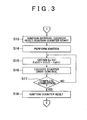
- a diffusion coefficient c (t0) of the air/fuel ratio is obtained on the basis of the count value of the ignition interval t0.
- the diffusion coefficient c (t0) of the air/fuel mixture is obtained by the function using the ignition interval t0 as the variable.
- the combustion energy energy generated by the combustion
- the diffusion coefficient c (t0) serves to reflect the decrease in the combustion energy in an operation for obtaining the combustion energy.
- the diffusion coefficient c (t0) increases until passage of the predetermined time A because of a constant delay of time taken from vaporization of the injected fuel to formation of the air/fuel mixture.
- the predetermined time A takes only several tens milliseconds, and the value within 1 second at the maximum.
- step S9 the diffusion coefficient c (t0) corresponding to the ignition interval t0 is obtained by referring to the map stored in the ROM.
- step S10 the combustion energy Ec (t0) generated by combustion of the fuel injected in step S7 is obtained using the equation (2) as follows.
- step S11 the kinetic energy Ea (t1) supplied to the crankshaft 14 is estimated on the basis of the combustion energy Ec (t0) obtained in step S10.
- the specific method for estimating the kinetic energy Ea (t1) will be described later.
- the time t1 represents the passage of time from the ignition, and the kinetic energy Ea (t1) is expressed as a function of passage of time from the ignition.
- step S12 it is determined whether the request for re-starting the engine 1 has been issued.
- step S12 If No is obtained in step S12, that is, no request for re-starting the engine 1 has been issued, the process returns to step S9 from where the process is executed in the subsequent steps, that is, the state of the air/fuel mixture is determined in step S9, the combustion energy Ec (t0) is obtained in step S10 on the basis of the result determined in step S9, and the kinetic energy Ea (t1) is estimated in step S11.
- Equation (3) Ec Ef + Ea
- Ef represents the mechanical loss owing to an operation of the engine 1, for example, the energy consumption by the mechanical loss owing to the friction. This may be identified as the function of the rotational speed Ne of the crankshaft 14.
- the relationship between the rotational speed Ne and the energy loss Ef is preliminarily obtained by simulation or experiments.
- the relationship between the combustion energy Ec and the behavior of the crankshaft 14 in accordance therewith may be defined by the simulation. If the behavior of the crankshaft 14 is defined, it is possible to define the relationship between the combustion energy Ec and the rotational speed Ne of the crankshaft 14. Accordingly if the combustion energy Ec (t0) upon the ignition is obtained, the corresponding energy loss Ef may be defined. This makes it possible to obtain the kinetic energy Ea supplied to the crankshaft 14 by subtracting the defined energy loss Ef from the combustion energy Ec (t0) obtained by the initial combustion.
- each combustion energy Ec generated in the respective cylinders 2 is defined by the physical values P, V( ⁇ ), and T indicating the state of the air/fuel mixture in the respective cylinders 2.
- the diffusion coefficient of the air/fuel mixture does not have to be considered. This makes it possible to obtain the kinetic energy Ea of the crankshaft 14 corresponding to the combustion energy Ec obtained by each combustion in the respective cylinders.
- the thus obtained kinetic energy Ea is summed in correlation with the time passage t1 from the ignition so as to obtain the kinetic energy Ea of the crankshaft 14 generated by the combustion of the engine 1 as the function Ea (t1) correlated with the time passage t1.
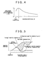
- Fig. 5 shows an example of estimating the kinetic energy Ea (t1) in accordance with the aforementioned method.
- the bold curve of the graph corresponds to the estimated values of the kinetic energy on the basis of the initial combustion energy Ec (t0).
- the combustion energy is added at every generation of the combustion in the respective cylinders 2 such that the estimated value Ea (t1) of the kinetic energy increases.
- the kinetic energy Ea (t1) decreases during the combustion owing to the mechanical loss.
- the target kinetic energy Et (t1) has to be set so as to sequentially increase the kinetic energy from the ignition until it reaches an equilibrium state at a predetermined level.
- the target kinetic energy Et (t1) is defined by the mechanical characteristics of the engine 1, which is preliminarily obtained by the simulation or experiments. Generally the estimated value Ea (t1) of the kinetic energy is relatively smaller than the target kinetic energy Et (t1) owing to the mechanical loss. Accordingly in the case where the combustion in the engine 1 is only used for the start-up, the kinetic energy may be insufficient by the amount corresponding to the hatched area shown in Fig. 5 .
- the energy corresponding to the hatched area as shown in Fig. 5 is compensated by the energy supplied from the starter motor 17 so as to obtain the target kinetic energy Et (t1).
- step S12 if Yes is obtained in step S12, that is, the re-start of the engine has been required, the process further proceeds to step S 13 in the flowchart of Fig. 3 where the ignition interval counter is reset and the ignition counter starts counting the time passage t1.
- the ignition is performed in the cylinder 2 in the expansion stroke in step S 14.
- step S 15 the start assist energy Es (t1) is calculated using the equation (4) in accordance with the time passage t1 of the ignition counter.
- the insufficient amount of the kinetic energy that cannot be covered by the kinetic energy Ea (t1) with respect to the target kinetic energy Et (t1) at the time passage t1 is obtained as the start assist energy Es (t1).
- the target kinetic energy Et (t1) is preliminarily stored in the ROM of the ECU 20, which is referred in time of necessity.
- step S16 the starter motor 17 is driven such that the start assist energy Es (t1) is supplied to the crankshaft 14.
- step S17 it is determined whether the complete combustion where the combustion of the engine 1 is continuously performed is obtained. If No is obtained in step S 17, the process returns to step S 15 where the control routine is executed repeatedly. The determination with respect to the complete combustion in step S 17 may be made on the basis of variation in the crank angle detected by the crank angle sensor 25, for example. If Yes is obtained in step S 17, that is, the complete combustion is obtained, the process proceeds to step S 18 where the ignition counter is reset, and the process returns to step S1.
- the energy required for starting the engine 1 is preliminarily set as the target kinetic energy Et (t1).
- the difference between the target kinetic energy Et (t1) and the kinetic energy Ea (t1) generated by combustion is obtained as the start assist energy Es (t1).
- the start assist energy Es (t1) is supplied from the starter motor 17 to the engine 1. Therefore, the target kinetic energy Et (t1) is supplied to the engine 1 so as to be smoothly started while saving the energy.
- the target kinetic energy Et (t1) is preliminarily obtained, and a range of the kinetic energy generated by the combustion is also estimated.
- This makes it possible to obtain the energy to be supplied to the engine 1 from the starter motor 17 to a certain degree. This eliminates the need of mounting unnecessarily large starter motor, releasing the limitation of mounting the starter motor as well as reducing the cost thereof.
- the energy required for starting the engine cannot be obtained in advance, and the insufficient energy is compensated by the starter motor after identifying the insufficiency in the energy. That is, the conventional technology fails to obtain the energy for compensating the insufficient energy in advance. Therefore, the size of the starter has to be larger to supply more energy just in case for unexpected circumstances.
- an appropriate size of the starter motor 17 can be set, thus reducing size and weight thereof.
- the ECU 20 serves to control energy, obtain the combustion energy, estimate the kinetic energy, and identify the cylinder in the expansion stroke.
- the ECU 20 further serves to cause the fuel injection valve 4 corresponding to the cylinder 2 in the expansion stroke to inject the fuel.
- the ROM of the ECU 20 serves to store the target kinetic energy.
- the target kinetic energy may be set from various aspects.
- the target kinetic energy may be set as a theoretical minimum kinetic energy for obtaining the complete combustion state of the engine 1, for example. In this case, the energy consumption upon start of the engine may be minimized. Therefore, it is preferable for the case of executing the idling stop control where the operation of the engine 1 to be stopped or re-started is frequently repeated.
- the start of the engine according to the invention is not limited to the re-start of the engine upon idling stop state.
- the invention may be applied to the start of the engine corresponding to ON operation of the ignition key, for example. If the target kinetic energy is set to the theoretical minimum value, the noise or vibration caused by the start of the engine may become so small that the occupant of the vehicle does not notice the start of the engine, and may misunderstand that the start of the engine has failed. In order to avoid the aforementioned misunderstanding, the target kinetic energy may be larger than the theoretical minimum value so as to make sure that the occupant feels the start of the engine 1.
- the invention may be applied to various cases of starting the internal combustion engine, for example, re-start of the engine of the hybrid vehicle including the internal combustion engine and the electric motor.
- the secondary energy supply source is formed as the electric motor.
- various types of devices may be used as the secondary energy supply source.
- the internal combustion engine to be started may be provided with another internal combustion engine.
- the secondary energy supply source may be formed as the device that stores the energy under the pressure of the fluid such as the air pressure and releases the stored energy upon start of the engine.
- the pressure P and the temperature T of the combustion chamber are directly detected by the sensors 23, 24, respectively as the physical values indicating the state of the air/fuel mixture within the combustion chamber.
- the physical values correlated with the pressure and the temperature of the combustion chamber for example, temperature of the engine cooling water, the time passage from the stop of the engine, may be detected such that the state of the air/fuel mixture is determined using the map or the function.
- the primary energy supply source is structured to generate combustion within the cylinder 2 of the engine 1 so as to supply the kinetic energy.
- the primary energy supply source may be formed as the device having the other structure. It is assumed, in the aforementioned embodiment, that the kinetic energy supplied from the primary energy supply source is not sufficient for the target kinetic energy. However, the embodiment may be structured to supply negative kinetic energy (apply resistance to the rotary motion of the crankshaft) from the secondary energy supply source in the case where the kinetic energy supplied from the primary energy supply source exceeds the target kinetic energy such that the total energy supplied from the primary and the secondary energy supply sources becomes equal to the target kinetic energy.
- the number of the energy supply source may be arbitrarily set so long as the total energy supplied from the energy supply sources becomes equal to the predetermined target kinetic energy.
- the target kinetic energy is preliminarily set, and the supplied energy is controlled to become equal to the target kinetic energy.
- the internal combustion engine is reliably started while preventing over-speed upon the start of the engine and avoiding various problems owing to the over-speed, for example, deterioration in the fuel efficiency and noise.
- a combustion energy is generated by combusting a fuel that has been injected into a cylinder (2) in an expansion stroke when the internal combustion engine (1) is stopped.
- the combustion energy (Ec (t0)) generated by combusting the fuel is obtained based on a state of an air/fuel mixture within the cylinder (2) to which the fuel has been injected. Based on the obtained combustion energy, a kinetic energy (Ea (t1)) to be supplied to the internal combustion engine from a primary energy supply source is estimated. A difference between a predetermined target kinetic energy (Et (t1)) required for starting the internal combustion engine subsequent to the start of combustion and the estimated kinetic energy to be supplied from the primary energy supply source is obtained. The kinetic energy (Es (t1)) corresponding to the obtained difference is supplied from a secondary energy supply source in the form of a starter motor (17).
Landscapes
- Engineering & Computer Science (AREA)
- Chemical & Material Sciences (AREA)
- Combustion & Propulsion (AREA)
- Mechanical Engineering (AREA)
- General Engineering & Computer Science (AREA)
- Combined Controls Of Internal Combustion Engines (AREA)
- Electrical Control Of Air Or Fuel Supplied To Internal-Combustion Engine (AREA)
- Output Control And Ontrol Of Special Type Engine (AREA)
Applications Claiming Priority (2)
| Application Number | Priority Date | Filing Date | Title |
|---|---|---|---|
| JP2002275622A JP3758626B2 (ja) | 2002-09-20 | 2002-09-20 | 内燃機関の始動方法及び始動装置並びにそれらに用いる始動エネルギの推定方法及び装置 |
| EP03021247A EP1400687B1 (en) | 2002-09-20 | 2003-09-18 | Starting method and starting device of internal combustion engine, method and device of estimating starting energy employed for starting method and starting device |
Related Parent Applications (1)
| Application Number | Title | Priority Date | Filing Date |
|---|---|---|---|
| EP03021247A Division EP1400687B1 (en) | 2002-09-20 | 2003-09-18 | Starting method and starting device of internal combustion engine, method and device of estimating starting energy employed for starting method and starting device |
Publications (3)
| Publication Number | Publication Date |
|---|---|
| EP1696121A2 EP1696121A2 (en) | 2006-08-30 |
| EP1696121A3 EP1696121A3 (en) | 2006-10-25 |
| EP1696121B1 true EP1696121B1 (en) | 2009-06-17 |
Family
ID=31944616
Family Applications (2)
| Application Number | Title | Priority Date | Filing Date |
|---|---|---|---|
| EP03021247A Expired - Lifetime EP1400687B1 (en) | 2002-09-20 | 2003-09-18 | Starting method and starting device of internal combustion engine, method and device of estimating starting energy employed for starting method and starting device |
| EP06111940A Expired - Lifetime EP1696121B1 (en) | 2002-09-20 | 2003-09-18 | Starting method and starting device of internal combustion engine, method and device of estimating starting energy employed for starting method and starting device |
Family Applications Before (1)
| Application Number | Title | Priority Date | Filing Date |
|---|---|---|---|
| EP03021247A Expired - Lifetime EP1400687B1 (en) | 2002-09-20 | 2003-09-18 | Starting method and starting device of internal combustion engine, method and device of estimating starting energy employed for starting method and starting device |
Country Status (4)
| Country | Link |
|---|---|
| US (1) | US7096840B2 (ja) |
| EP (2) | EP1400687B1 (ja) |
| JP (1) | JP3758626B2 (ja) |
| DE (2) | DE60328056D1 (ja) |
Families Citing this family (24)
| Publication number | Priority date | Publication date | Assignee | Title |
|---|---|---|---|---|
| JP4158583B2 (ja) * | 2003-04-11 | 2008-10-01 | トヨタ自動車株式会社 | 内燃機関の始動装置 |
| JP2005127169A (ja) * | 2003-10-22 | 2005-05-19 | Hitachi Ltd | 内燃機関の制御方法 |
| DE102004028092A1 (de) * | 2004-06-09 | 2005-12-29 | Robert Bosch Gmbh | Verfahren zum Start einer Brennkraftmaschine |
| JP4012893B2 (ja) | 2004-06-11 | 2007-11-21 | トヨタ自動車株式会社 | 内燃機関の制御装置 |
| DE102004037129B4 (de) * | 2004-07-30 | 2016-02-11 | Robert Bosch Gmbh | Vorrichtung und Verfahren zur Steuerung einer Brennkraftmaschine bei einem Start |
| JP2006183630A (ja) * | 2004-12-28 | 2006-07-13 | Nissan Motor Co Ltd | 内燃機関及びその始動方法 |
| JP4338659B2 (ja) | 2005-03-02 | 2009-10-07 | 株式会社日立製作所 | 内燃機関の始動方法及び始動装置 |
| US7278388B2 (en) * | 2005-05-12 | 2007-10-09 | Ford Global Technologies, Llc | Engine starting for engine having adjustable valve operation |
| DE102006045661B4 (de) * | 2006-09-27 | 2018-08-02 | Robert Bosch Gmbh | Verfahren zum Starten einer Brennkraftmaschine |
| JP4834519B2 (ja) * | 2006-11-10 | 2011-12-14 | アイシン精機株式会社 | 車両の駆動源制御装置 |
| JP4379467B2 (ja) | 2006-12-11 | 2009-12-09 | 日産自動車株式会社 | 電池モジュール |
| DE102007023225A1 (de) * | 2007-05-18 | 2008-11-20 | Bayerische Motoren Werke Aktiengesellschaft | Vorrichtung und Verfahren zum Starten einer Brennkraftmaschine |
| KR100999618B1 (ko) * | 2008-06-11 | 2010-12-08 | 기아자동차주식회사 | 아이들 스톱 앤 고 기능 확인 방법 |
| US8140247B2 (en) * | 2008-11-06 | 2012-03-20 | Ford Global Technologies, Llc | Control of intake pressure for restart-enabled idle stop |
| US8412443B2 (en) * | 2008-11-06 | 2013-04-02 | Ford Global Technologies, Llc | Engine shutdown control |
| US7827975B1 (en) * | 2009-05-28 | 2010-11-09 | Ford Global Technologies, Llc | Direct-start engine operation utilizing multi-strike ignition |
| US7962278B1 (en) * | 2009-12-16 | 2011-06-14 | Ford Global Technologies, Llc | Method for starting an engine |
| WO2012111147A1 (ja) * | 2011-02-18 | 2012-08-23 | トヨタ自動車株式会社 | 内燃機関の制御装置 |
| US9404461B2 (en) | 2013-05-08 | 2016-08-02 | Ford Global Technologies, Llc | Method and system for engine starting |
| JP2015117611A (ja) * | 2013-12-18 | 2015-06-25 | トヨタ自動車株式会社 | ベルト張力制御装置 |
| JP2016200051A (ja) * | 2015-04-09 | 2016-12-01 | トヨタ自動車株式会社 | エンジン始動制御装置 |
| JP6504039B2 (ja) * | 2015-11-30 | 2019-04-24 | 株式会社デンソー | エンジン始動装置 |
| JP6733288B2 (ja) * | 2016-04-27 | 2020-07-29 | いすゞ自動車株式会社 | ハイブリッド車両 |
| US11168657B2 (en) * | 2020-02-28 | 2021-11-09 | Ford Global Technologies, Llc | Methods and system for a stop/start vehicle |
Family Cites Families (19)
| Publication number | Priority date | Publication date | Assignee | Title |
|---|---|---|---|---|
| US4009695A (en) * | 1972-11-14 | 1977-03-01 | Ule Louis A | Programmed valve system for internal combustion engine |
| DE3117144A1 (de) * | 1981-04-30 | 1982-11-18 | Fa. Emil Bender, 5900 Siegen | Anlassvorrichtung fuer einen mehrzylindrigen otto-motor |
| US4364343A (en) * | 1981-05-08 | 1982-12-21 | General Motors Corporation | Automatic engine shutdown and restart system |
| US4462348A (en) * | 1981-08-31 | 1984-07-31 | Ford Motor Company | Engine starting system |
| JPH07119594A (ja) | 1993-09-02 | 1995-05-09 | Nippondenso Co Ltd | 車両用内燃機関始動装置 |
| FR2726330B1 (fr) * | 1994-10-27 | 1997-01-17 | Bernard Jean Louis | Dispositif d'aide au demarrage d'un vehicule |
| US6098585A (en) * | 1997-08-11 | 2000-08-08 | Ford Global Technologies, Inc. | Multi-cylinder four stroke direct injection spark ignition engine |
| DE19743492B4 (de) | 1997-10-01 | 2014-02-13 | Robert Bosch Gmbh | Verfahren zum Starten einer Brennkraftmaschine insbesondere eines Kraftfahrzeugs |
| JP2000004929A (ja) | 1998-06-18 | 2000-01-11 | Matsushita Electric Works Ltd | ヘアーアイロン |
| DE19830974B4 (de) * | 1998-07-10 | 2005-11-03 | Fev Motorentechnik Gmbh | Kaltstartverfahren für eine drosselfreie Mehrzylinder-Kolbenbrennkraftmaschine |
| JP3546735B2 (ja) | 1999-01-18 | 2004-07-28 | 日産自動車株式会社 | エンジンの始動制御装置 |
| US6125808A (en) * | 1999-04-07 | 2000-10-03 | Timewell; Richard R. | Apparatus and method for starting an internal combustion engine |
| DE19918513C1 (de) * | 1999-04-23 | 2000-11-02 | Daimler Chrysler Ag | Elektrische Antriebsanordnung für eine Brennkraftmaschine in einem Kraftfahrzeug |
| US6357409B1 (en) * | 2000-05-23 | 2002-03-19 | Ford Global Technologies, Inc. | Method and system for starting a camless internal combustion engine |
| JP2002004929A (ja) | 2000-06-16 | 2002-01-09 | Mitsubishi Motors Corp | 筒内噴射型内燃機関の始動装置 |
| JP3821202B2 (ja) | 2000-06-16 | 2006-09-13 | 三菱自動車工業株式会社 | 筒内噴射型内燃機関の始動装置 |
| DE10042370A1 (de) * | 2000-08-29 | 2002-03-14 | Bosch Gmbh Robert | Verfahren zum Starten eines Hybridantriebs |
| JP2002089417A (ja) | 2000-09-13 | 2002-03-27 | Unisia Jecs Corp | エンジン始動装置 |
| WO2002042618A2 (fr) * | 2000-11-27 | 2002-05-30 | Ribakov Anatolij Aleksandrovic | Procede de demarrage par injection d'un moteur a combustion interne |
-
2002
- 2002-09-20 JP JP2002275622A patent/JP3758626B2/ja not_active Expired - Fee Related
-
2003
- 2003-09-02 US US10/652,484 patent/US7096840B2/en not_active Expired - Fee Related
- 2003-09-18 EP EP03021247A patent/EP1400687B1/en not_active Expired - Lifetime
- 2003-09-18 DE DE60328056T patent/DE60328056D1/de not_active Expired - Lifetime
- 2003-09-18 EP EP06111940A patent/EP1696121B1/en not_active Expired - Lifetime
- 2003-09-18 DE DE60311044T patent/DE60311044T2/de not_active Expired - Lifetime
Also Published As
| Publication number | Publication date |
|---|---|
| EP1696121A2 (en) | 2006-08-30 |
| DE60328056D1 (de) | 2009-07-30 |
| EP1400687A2 (en) | 2004-03-24 |
| US7096840B2 (en) | 2006-08-29 |
| EP1696121A3 (en) | 2006-10-25 |
| DE60311044T2 (de) | 2007-08-16 |
| DE60311044D1 (de) | 2007-02-22 |
| EP1400687B1 (en) | 2007-01-10 |
| JP2004108340A (ja) | 2004-04-08 |
| EP1400687A3 (en) | 2005-01-12 |
| US20040055553A1 (en) | 2004-03-25 |
| JP3758626B2 (ja) | 2006-03-22 |
Similar Documents
| Publication | Publication Date | Title |
|---|---|---|
| EP1696121B1 (en) | Starting method and starting device of internal combustion engine, method and device of estimating starting energy employed for starting method and starting device | |
| US8364386B2 (en) | Stop-start control apparatus and method for an internal combustion engine | |
| US8442747B2 (en) | Cylinder air mass prediction systems for stop-start and hybrid electric vehicles | |
| US7066128B2 (en) | Engine controller for starting and stopping engine | |
| EP1825122B8 (en) | Engine start control apparatus, engine start control method, and motor vehicle equipped with engine start control apparatus | |
| JP4550627B2 (ja) | 内燃機関の停止制御方法および停止制御装置 | |
| EP1809879B1 (en) | Device and method for stopping an engine | |
| EP1846648B1 (en) | Control apparatus for internal combustion engine | |
| US7131413B2 (en) | Start control apparatus of internal combustion engine | |
| EP1881188A1 (en) | Start controller of internal combustion engine | |
| US20060196460A1 (en) | Starting method and system for internal combustion engine | |
| US7134412B2 (en) | Method for increasing the reproducibility of the start-up during start-stop operation of an internal combustion engine | |
| JP2010159770A (ja) | エンジン始動制御装置、その方法及びそれを搭載した車両 | |
| JP5075145B2 (ja) | 内燃機関の制御装置 | |
| US6769401B2 (en) | Power output control system for internal combustion engine | |
| US20040144369A1 (en) | Method and system for providing fuel injection time scheduling for internal combustion engines using engine speed prediction | |
| US11125176B2 (en) | Methods and system for determining engine air-fuel ratio imbalance | |
| JP2005307826A (ja) | 内燃機関の始動制御装置 | |
| JP2007032324A (ja) | 内燃機関の制御装置 | |
| JP4811305B2 (ja) | 車両用エンジンの自動停止装置 | |
| EP1234969B1 (en) | Method and apparatus for determining fuel supply amount of internal combustion engine | |
| JP2003206775A (ja) | 自動変速機搭載車用内燃機関の制御装置 | |
| JP2023101902A (ja) | 内燃機関の始動制御装置 |
Legal Events
| Date | Code | Title | Description |
|---|---|---|---|
| PUAI | Public reference made under article 153(3) epc to a published international application that has entered the european phase |
Free format text: ORIGINAL CODE: 0009012 |
|
| 17P | Request for examination filed |
Effective date: 20060329 |
|
| AC | Divisional application: reference to earlier application |
Ref document number: 1400687 Country of ref document: EP Kind code of ref document: P |
|
| AK | Designated contracting states |
Kind code of ref document: A2 Designated state(s): DE FR IT |
|
| PUAL | Search report despatched |
Free format text: ORIGINAL CODE: 0009013 |
|
| AK | Designated contracting states |
Kind code of ref document: A3 Designated state(s): DE FR IT |
|
| 17Q | First examination report despatched |
Effective date: 20070604 |
|
| AKX | Designation fees paid |
Designated state(s): DE FR IT |
|
| R17C | First examination report despatched (corrected) |
Effective date: 20071213 |
|
| GRAP | Despatch of communication of intention to grant a patent |
Free format text: ORIGINAL CODE: EPIDOSNIGR1 |
|
| GRAS | Grant fee paid |
Free format text: ORIGINAL CODE: EPIDOSNIGR3 |
|
| GRAA | (expected) grant |
Free format text: ORIGINAL CODE: 0009210 |
|
| AC | Divisional application: reference to earlier application |
Ref document number: 1400687 Country of ref document: EP Kind code of ref document: P |
|
| AK | Designated contracting states |
Kind code of ref document: B1 Designated state(s): DE FR IT |
|
| REF | Corresponds to: |
Ref document number: 60328056 Country of ref document: DE Date of ref document: 20090730 Kind code of ref document: P |
|
| PLBE | No opposition filed within time limit |
Free format text: ORIGINAL CODE: 0009261 |
|
| STAA | Information on the status of an ep patent application or granted ep patent |
Free format text: STATUS: NO OPPOSITION FILED WITHIN TIME LIMIT |
|
| 26N | No opposition filed |
Effective date: 20100318 |
|
| PGFP | Annual fee paid to national office [announced via postgrant information from national office to epo] |
Ref country code: DE Payment date: 20100915 Year of fee payment: 8 |
|
| PGFP | Annual fee paid to national office [announced via postgrant information from national office to epo] |
Ref country code: FR Payment date: 20110922 Year of fee payment: 9 |
|
| PGFP | Annual fee paid to national office [announced via postgrant information from national office to epo] |
Ref country code: IT Payment date: 20110919 Year of fee payment: 9 |
|
| REG | Reference to a national code |
Ref country code: FR Ref legal event code: ST Effective date: 20130531 |
|
| PG25 | Lapsed in a contracting state [announced via postgrant information from national office to epo] |
Ref country code: DE Free format text: LAPSE BECAUSE OF NON-PAYMENT OF DUE FEES Effective date: 20130403 |
|
| PG25 | Lapsed in a contracting state [announced via postgrant information from national office to epo] |
Ref country code: IT Free format text: LAPSE BECAUSE OF NON-PAYMENT OF DUE FEES Effective date: 20120918 Ref country code: FR Free format text: LAPSE BECAUSE OF NON-PAYMENT OF DUE FEES Effective date: 20121001 |
|
| REG | Reference to a national code |
Ref country code: DE Ref legal event code: R119 Ref document number: 60328056 Country of ref document: DE Effective date: 20130403 |