EP1695616A2 - Transporteur de gobelet trayeur - Google Patents
Transporteur de gobelet trayeur Download PDFInfo
- Publication number
- EP1695616A2 EP1695616A2 EP06076229A EP06076229A EP1695616A2 EP 1695616 A2 EP1695616 A2 EP 1695616A2 EP 06076229 A EP06076229 A EP 06076229A EP 06076229 A EP06076229 A EP 06076229A EP 1695616 A2 EP1695616 A2 EP 1695616A2
- Authority
- EP
- European Patent Office
- Prior art keywords
- teat cup
- cup carrier
- teat
- carrier
- feed platform
- Prior art date
- Legal status (The legal status is an assumption and is not a legal conclusion. Google has not performed a legal analysis and makes no representation as to the accuracy of the status listed.)
- Withdrawn
Links
- 241001465754 Metazoa Species 0.000 claims abstract description 73
- 239000008267 milk Substances 0.000 claims abstract description 50
- 235000013336 milk Nutrition 0.000 claims abstract description 50
- 210000004080 milk Anatomy 0.000 claims abstract description 50
- 238000004140 cleaning Methods 0.000 claims abstract description 45
- 238000003860 storage Methods 0.000 claims abstract description 31
- 230000010349 pulsation Effects 0.000 claims abstract description 3
- 210000002445 nipple Anatomy 0.000 claims description 300
- 238000002203 pretreatment Methods 0.000 claims description 20
- 230000007257 malfunction Effects 0.000 claims description 12
- 239000012530 fluid Substances 0.000 claims description 10
- 238000005507 spraying Methods 0.000 claims description 10
- 239000012535 impurity Substances 0.000 claims description 9
- 238000013459 approach Methods 0.000 claims description 4
- 238000004891 communication Methods 0.000 claims description 4
- 238000001035 drying Methods 0.000 claims description 4
- 238000010438 heat treatment Methods 0.000 claims description 4
- 210000003608 fece Anatomy 0.000 claims description 3
- 210000001364 upper extremity Anatomy 0.000 claims description 3
- 238000011109 contamination Methods 0.000 claims description 2
- 239000010871 livestock manure Substances 0.000 claims description 2
- 241000283690 Bos taurus Species 0.000 description 68
- 235000013365 dairy product Nutrition 0.000 description 10
- 239000000969 carrier Substances 0.000 description 9
- 238000012544 monitoring process Methods 0.000 description 8
- 230000033001 locomotion Effects 0.000 description 7
- 230000007704 transition Effects 0.000 description 5
- 230000008878 coupling Effects 0.000 description 4
- 238000010168 coupling process Methods 0.000 description 4
- 238000005859 coupling reaction Methods 0.000 description 4
- 238000004519 manufacturing process Methods 0.000 description 4
- 210000000481 breast Anatomy 0.000 description 3
- 238000007599 discharging Methods 0.000 description 3
- 238000006073 displacement reaction Methods 0.000 description 3
- 230000002349 favourable effect Effects 0.000 description 3
- 238000005303 weighing Methods 0.000 description 3
- 230000001680 brushing effect Effects 0.000 description 2
- 238000010276 construction Methods 0.000 description 2
- 244000144980 herd Species 0.000 description 2
- 238000000034 method Methods 0.000 description 2
- 230000008569 process Effects 0.000 description 2
- 208000031872 Body Remains Diseases 0.000 description 1
- 230000003213 activating effect Effects 0.000 description 1
- 239000000654 additive Substances 0.000 description 1
- 230000002411 adverse Effects 0.000 description 1
- 238000001514 detection method Methods 0.000 description 1
- 235000013325 dietary fiber Nutrition 0.000 description 1
- 229940079593 drug Drugs 0.000 description 1
- 239000003814 drug Substances 0.000 description 1
- 230000002708 enhancing effect Effects 0.000 description 1
- 230000036541 health Effects 0.000 description 1
- 230000006872 improvement Effects 0.000 description 1
- 238000012423 maintenance Methods 0.000 description 1
- 238000005259 measurement Methods 0.000 description 1
- 230000011664 signaling Effects 0.000 description 1
- 230000004936 stimulating effect Effects 0.000 description 1
Images


Classifications
-
- A—HUMAN NECESSITIES
- A01—AGRICULTURE; FORESTRY; ANIMAL HUSBANDRY; HUNTING; TRAPPING; FISHING
- A01J—MANUFACTURE OF DAIRY PRODUCTS
- A01J7/00—Accessories for milking machines or devices
- A01J7/04—Accessories for milking machines or devices for treatment of udders or teats, e.g. for cleaning
-
- A—HUMAN NECESSITIES
- A01—AGRICULTURE; FORESTRY; ANIMAL HUSBANDRY; HUNTING; TRAPPING; FISHING
- A01J—MANUFACTURE OF DAIRY PRODUCTS
- A01J5/00—Milking machines or devices
- A01J5/003—Movable milking machines
-
- A—HUMAN NECESSITIES
- A01—AGRICULTURE; FORESTRY; ANIMAL HUSBANDRY; HUNTING; TRAPPING; FISHING
- A01J—MANUFACTURE OF DAIRY PRODUCTS
- A01J5/00—Milking machines or devices
- A01J5/017—Automatic attaching or detaching of clusters
- A01J5/0175—Attaching of clusters
-
- A—HUMAN NECESSITIES
- A01—AGRICULTURE; FORESTRY; ANIMAL HUSBANDRY; HUNTING; TRAPPING; FISHING
- A01J—MANUFACTURE OF DAIRY PRODUCTS
- A01J7/00—Accessories for milking machines or devices
- A01J7/02—Accessories for milking machines or devices for cleaning or sanitising milking machines or devices
- A01J7/025—Teat cup cleaning, e.g. by rinse jetters or nozzles
Definitions
- the invention relates to a teat cup carrier for a feed platform.
- Such a teat cup carrier is known from US-A1-2002/0033138.
- Said US-application discloses a system for enhancing the efficiency of milking large herds of animals.
- Said system comprises a feed platform with individual stalls, each for at least partially confining one animal.
- Each stall has its own teat cups carried by respective teat cup carriers, and its own feed trough.
- At the circumference of the platform there is provided a connection area where the teat cups are connected to the teats of an animal that is present on the platform.
- stationary connecting robots known per se or pivoting robots or robots moving along rails.
- An entrance area and an exit area of the platform are wide enough to allow simultaneous access of several animals to at least two stalls respectively simultaneous exit of several animals from at least two stalls.
- the entrance area is provided with a movable closing element, such as a gate, and is opened in a controlled manner in order to admit a number of animals to a waiting area adjacent to the platform.
- each stall has an operated entrance gate so that animals can get access from the waiting area to a stall on the platform.
- the known system comprises means for controlling the animal traffic, which means divide for example a herd of animals into groups.
- the entrance area is immediately followed by the udder cleaning area.
- the udder cleaning area itself is immediately followed by the area for connecting the teat cups.
- the teat cups are disconnected and the animal remains on the platform until the exit has been reached.
- the total time spent by an animal on the feed platform amounts to approximately 15 minutes.
- a teat cup carrier of the above-mentioned type is also known from US-A-4508058.
- a rotatable feed platform with individual stalls, each containing a feed trough and teat cups carried by respective teat cup carriers.
- the stalls are located on the platform in tangential direction and comprise an entrance gate and an exit gate.
- a stationary teat-cup-connecting robot which is capable of being coupled to the teat cups and which is suitable for connecting the teat cups to the teats of an animal that is present on the platform.
- In the stall there is supplied a predetermined amount of feed.
- a drawback of the known systems is that the motion speed of the platform depends on the connection time required by the connecting robot or the farmer for connecting the teat cups. It may also occur that the teat cups cannot be connected in the connection area, so that the animal cannot be milked during its stay on the platform and has to board the platform again for being milked. This may adversely affect the milk yield as well as the animal health.
- the invention aims at providing an alternative teat cup carrier.
- a multifunctional teat cup carrier is obtained by providing a teat cup carrier designed to be able to co-operate with a feed platform, which teat cup carrier is freely movable relative to the feed platform.
- the invention is based on the insight that the drawback in the state of the art is caused at least partially by the fact that the teat cup carrier, and consequently the teat cups, is coupled to the feed platform.
- the rotational speed of the feed platform does no longer need to depend on the connection of the teat cups and the connection of teat cups can also take place outside the connection area.
- the teat cup carriers do no longer need to be disposed on the feed platform.
- the teat cup carrier can be used to clean the feed platform.
- said teat cup carrier being also provided with a cleaning device for cleaning the feed platform.
- the cleaning device is provided with a device for determining the degree of contamination of the platform and for emitting contamination-degree-signals.
- the cleaning device preferably comprises a manure slide.
- the cleaning device may comprise a rotatable cleaning brush.
- the cleaning device comprises a sprayer for spraying and/or squirting a fluid on the platform.
- the sprayer is preferably a high-pressure sprayer.
- An improved cleaning is obtained if the cleaning device comprises a heating element for heating the fluid.
- the cleaning device preferably comprises a drying device for drying the feed platform.
- the cleaning device comprises a storage container for impurities
- the teat cup carrier can be active autonomously for a longer time without the impurities having to be discarded in the meantime.
- the storage container is provided with an outlet for impurities.
- the storage container may be removable as a whole.
- the teat cup carrier is preferably provided with a cleaning device for cleaning the storage container.
- teat cup carriers are not freely movable with respect to the feed platform.
- FR-A-2,649,858 It is also known per se from FR-A-2,649,858 to dispose the sets of teat cups separately from the platform.
- the housing system as used in FR-A-2,649,858 is not explicitly described, but since the animals have to enter the circular platform from within the platform it is most likely that the animals have to be led from the outside of the platform towards the inside.
- the assembly known from FR-A-2,649,858 also suffers from the disadvantage that a dairy animal is to be milked in a closed area, such as the stalls provided on the platform disclosed therein which limit the freedom of movement of a dairy animal to a high extent. Each stall is closed by two gates, so that this also restricts the free movement of animals since an animal has to board the platform at a specific position.
- teat cup carriers are not freely movable with respect to the feed platform.
- the teat cup carrier comprises a teat cup gripper for gripping and retaining a teat cup that is disposed on a teat cup holder.
- the teat cup holder may be arranged stationarily or be movable in an alternative embodiment.
- the teat cup carrier carries, besides teat cups, further milking means for milking an animal, the further milking means comprising at least a milk storage vessel for storing milk, a milking vacuum source and a pulsation vacuum source.
- the further milking means comprising at least a milk storage vessel for storing milk, a milking vacuum source and a pulsation vacuum source.
- the milk storage vessel is provided with a milk outlet.
- the milk storage vessel is an exchangeable milk storage vessel that may be transported for example as a whole to a milk factory.
- the freely movable teat cup carrier is a self-propelled (autonomous) mobile teat-cup-carrying robot and there is provided a control unit for controlling the functioning of the mobile teat-cup-carrying robot.
- the control unit preferably comprises a transmitting and receiving unit for communication with a control unit, in particular a control unit of the feed platform.
- a connecting device for connecting the teat cups to the teats of an animal may be a separate device, for the sake of simplicity of the construction it is advantageous if the teat cup carrier is provided with a connecting device for connecting a teat cup to the teats of an animal that is present on the feed platform.
- the connecting device is provided with a gripping device for gripping a teat cup that is disposed on the teat cup carrier.
- the teat cup carrier is provided with a teat-position-determining device for determining the position of a teat of an animal that is present on the feed platform.
- the teat-position-determining device is in particular disposed on the connecting device.
- the connecting device comprises a robot arm, in particular for carrying the gripping device.
- the teat cup carrier comprises a measuring device for measuring milk parameters. In this manner the teat cup carrier can determine for example whether or not an amount of milk obtained is suitable for human consumption.
- the teat cup carrier comprises a drive that is controllable by the control unit.
- the teat cup carrier is provided with a teat-cup-cleaning device for cleaning a teat cup. This makes it possible for the teat cup carrier to ensure itself the cleaning of the teat cups.
- the teat cup carrier is provided with a milking-pre-treatment device for performing a milking-pre-treatment on an animal on the feed platform. This makes it possible for the teat cup carrier to ensure itself the pre-treatment of an animal, in particular the teats of an animal.
- a correct pre-treatment can be obtained in that the milking-pre-treatment device is provided with a device for determining the position of a teat of an animal on the feed platform. It is in particular advantageous if the milking-pre-treatment device comprises a robot arm.
- the milking-pre-treatment device comprises a spraying device for spraying and/or squirting a fluid on the teat.
- the teat cup carrier is provided with a milking-post-treatment device for performing a milking-post-treatment on an animal on the feed platform. This makes it possible for the teat cup carrier to ensure itself the post-treatment of an animal, in particular the teats of an animal.
- a correct post-treatment can be obtained if the milking-post-treatment device is provided with a device for determining the position of a teat of an animal. It is in particular advantageous if the milking-post-treatment device comprises a robot arm.
- the milking-post-treatment device comprises a spraying device for spraying and/or squirting a fluid on the teat.
- the teat cup carrier is provided with navigation means for navigating the teat cup carrier.
- the navigation means comprise position-determining means for determining the position of the teat cup carrier and for supplying position information.
- the teat cup carrier is preferably provided with its own energy supply, a rechargeable energy supply being in particular suitable for the purpose.
- the teat cup carrier is provided with a malfunction detector for detecting an internal malfunction.
- the teat cup carrier is preferably provided with an alarm-signal-issuing device for issuing an alarm signal with the aid of data from the malfunction detector. Said alarm signal may be sent for example to the farmer or the operator of the teat cup carrier to enable the person in question to take the necessary measures for repairing the malfunction.
- the safety of the teat cup carrier is further improved in an embodiment in which the teat cup carrier is capable of being deactivated with the aid of data from the malfunction detector.
- the teat cup carrier is also capable of moving over the feed platform, in a favourable embodiment of a teat cup carrier according to the invention, the teat cup carrier is dimensioned in such a way that it is capable of being placed as a whole under an animal between its forelegs and hind legs.
- the mobile robot is characterized in that the teat cup carrier is provided with a proximity detector for detecting the proximity of an object.
- the teat cup carrier and/or other objects may be prevented from being damaged as a result of undesired contacts with the teat cup carrier if the teat cup carrier is characterized in that it is provided with a protecting device for protecting at least a part of the teat cup carrier, which protecting device is capable of being brought from an inactive position into an active protecting position.
- a protecting device may be a protecting cap, an airbag or the like.
- the protecting device is in particular capable of being brought from an inactive position into an active protecting position with the aid of data from the proximity detector.
- the proximity detector comprises a camera.
- the proximity detector may comprise an approach sensor.
- the teat cup carrier in an embodiment of a teat cup carrier according to the invention in which the teat cup carrier is provided with a signal-issuing device for issuing a perceptible signal, the teat cup carrier is capable of signalling its presence to its environment. Besides, said signal-issuing device may be used for making sounds audible or perceptible to an animal. In a preferred embodiment, the signal-issuing device is capable of being activated with the aid of data from the proximity detector.
- the proximity detector is in particular connectable to the navigation means in order to make it possible for the teat cup carrier to navigate around an obstacle.
- the teat cup carrier is provided with an animal-recognition device for recognizing an animal.
- the animal-recognition device is in particular connectable to the control unit for supplying recognition information to the control unit.
- teat cups are connected to the teats of the cow.
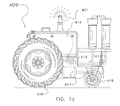
- the teat cups 411 are carried by an autonomous, mobile teat-cup-carrying robot 409 that is capable of moving freely on and/or beside a feed platform.
- the teat-cup-carrying robot 409 is shown in side view in Figure 1a.
- the mobile teat-cup-carrying robot 409 carries four teat cups 411, two of which are visible in the figure.
- the teat cups 411 are each connected via a teat cup line 412 to a milk storage vessel 414 to which the milk is conveyed with the aid of a vacuum pump system 413.
- the teat-cup-carrying robot 409 is provided with wheels 418.
- the wheels 418 are driven by a drive unit 417, such as an electric motor.
- the milk storage vessel 414 is provided on its lower side with a non-shown milk outlet through which the milk can be conveyed to a milk tank.
- the teat-cup-carrying robot 409 is provided with a (non-shown) position-determining device, which may be a radar, a GPS-system component or the like. This makes it possible to determine the momentary position of the teat-cup-carrying robot 409.
- the teat-cup-carrying robot 409 comprises a transmitting/receiving device 421 for transmitting and receiving position data and control commands, as will be explained hereinafter in further detail.
- FIG. 1b shows an embodiment of a mobile, autonomous teat-cup-connecting robot 419.
- the teat-cup-connecting robot 419 comprises an upwardly movable teat cup gripper 420.
- the teat-cup-connecting robot 419 does not have a milk storage vessel.
- a transmitting/receiving device 422 is suitable for receiving data from the milking system control unit and is connected to a control unit 423a, which does not only ensure the control of the displacement of the mobile teat-cup-connecting robot 419, but also controls the functioning of the teat cup gripper 420.
- the teat-cup-connecting robot 419 and the teat-cup-carrying robot 409 are able to co-operate.
- the teat-cup-connecting robot 419 is moved to the position of a cow to be milked. This is possible by displacement across a feed platform 352 or beside a feed platform 352.
- the teat-cup-carrying robot 409 is moved to a position near the teat-cup-connecting robot, so that the teat cup gripper 420 of the teat-up-connecting robot 419 is able to grip the teat cups 411 carried by the teat-cup-carrying robot 409.
- the position-determining means 423 that detect the position of the teat cups 411 on the teat-cup-carrying robot 409 and move the teat cup gripper 420 in such a way that the teat cups are gripped.
- the teat-cup-carrying robot 409 and the teat cup gripper 420 are then moved in such a way that a teat cup is located under a teat, after which, by moving the teat cup gripper 420 upwardly, the teat cup is connected to the teat through vacuum.
- the teat-cup-carrying robot 409 and the teat-cup-connecting robot 419 continue to move synchronously with each other and with the feed platform 352, which is achieved by the mutual communication by means of the transmitting/receiving devices 421, 422.
- the teat-cup-connecting robot 419 moves to the next cow that is to be milked, while the teat-cup-carrying robot 409 continues to move synchronously with the feed platform 352 until the milking has been finished, which can take place in a customary manner, for example by flow measurement.
- the co-operation between the teat-cup-carrying robot 409 and the teat-cup-connecting robot 419 takes place directly, and the co-operation with the feed platform takes place indirectly
- the teat-cup-carrying robot 409 co-operates directly with the feed platform 352 and moves synchronously with the feed platform 352, for example under the control of a feeding system control unit, and that the teat-cup-connecting robot 419 grips the teat cups from the teat-cup-carrying robot by means of the position-determining means.
- the freely moving, mobile teat-cup-carrying robot co-operates directly with the feed platform 352.
- Figures 1c and 1d show diagrammatically a mobile, autonomous teat-cup-carrying robot 424 with an integrated teat-cup-connecting device.
- the robot 424 is provided with a milk storage vessel 425, with energy supply means 426 for the robot and the relevant components, with an underpressure and/or overpressure system 427 for teat cups 428, with (non-shown) milk-analysing means, and with (non-shown) navigation means and a control unit for controlling the robot and the relevant components.
- the robot 424 Under the control of the milking system control unit the robot 424 is moved towards a cow to be milked, where the teat cups are connected to the relevant teats.
- the position of the teat relative to the teat cup 428 is then determined by the position-determining device 429, such as a laser sensor for detecting the position of the teats of the animal to be milked.
- a lifting device 430 for the teat cup 428 makes it possible for the teat cup 428 to be connected, by means of a substantially vertical movement, to the teat of the cow.
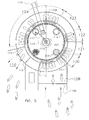
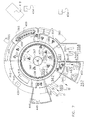
- FIG. 2 shows diagrammatically a partially cross-sectional side view of a mobile robot, in the embodiment shown the teat-cup-carrying robot 424 with an integrated teat-cup-connecting device, coupled to a multifunctional robot-treatment station 410.
- the robot 424 moves automatically to the multifunctional robot-treatment station 410.
- the multifunctional robot-treatment station 410 comprises a charging device 475 that is capable of being coupled automatically to the charging port 476 of the rechargeable energy supply 477 of the robot 424.
- a coupling detector which, upon detection of coupling of the charging device 475 to the charging port 476, activates the recharging.
- the multifunctional robot-treatment station 410 also comprises a milk outlet 478 for discharging milk from the milk storage vessel 425 of the robot 424.
- the milk outlet 478 comprises a sensor 479 for measuring the quality of the milk and for controlling a valve 480, in order to discharge milk that is suitable for human consumption to a milk tank via the milk tank outlet 481, or alternatively to discharge milk via an other outlet 482 to an other storage element.
- the milk outlet 478 is capable of being coupled automatically to the outlet 483 of the milk storage vessel 425. Also in this case there is provided a coupling detector for discharging the milk from the milk storage vessel 425 after a successful coupling has been detected.
- a teat-cup-cleaning device 484 comprising downwardly directed thorns having fluid outflow apertures at their ends is brought into the teat cups 428.
- the valve 480 is controlled in such a way that cleaning fluid can be discharged via the other outlet 482.
- the multifunctional robot-treatment station 410 further comprises a robot-cleaning device 485 comprising in the embodiment shown a sprayer for cleaning the robot.
- the multifunctional robot-treatment station may comprise other components for the maintenance and cleaning of the robot.
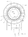
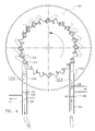
- Figure 3 shows cameras (or comparable following means) for monitoring the feed platform and following mobile units (in particular cows and mobile robots). Such cameras with associated software in the computer system may be used for monitoring the mobile units, and for identification, orientation and position determination of the mobile units.
- Figure 3 shows diagrammatically in plan view a camera monitoring system for a feed platform with position marks 486.
- the position marks 486 serve as position beacons, so that the camera monitoring system is capable of exactly determining the rotation position of the feed platform relative to the stationary world.
- the camera monitoring system comprises cameras which are disposed above the feed platform and have a field of vision that is shown in the figure by means of circles 487. The fields of vision overlap one another and cover the entire feed platform, the area on the inside of the feed platform and a strip on the outside beside the feed platform.
- the camera monitoring system is used to determine the exact position of the robots, if any, and to check same, and to determine the position of an animal on the feed platform.
- the data from the camera monitoring system are also used for the operation and control of the mobile teat-cup-carrying robots.
- teat-cup-carrying robot is capable of co-operating with any feed platform known per se with teat cups disposed thereon, the invention may in particular be applied to feed platforms without teat cups, some embodiments of which will be described hereinafter.
- FIG 4 shows diagrammatically in plan view a part of an embodiment of a movable feed platform 91 that is shown as a substantially disc-shaped one.
- the feed platform 91 is provided with separating means 92 for partially separating cows.
- the separating means 92 adjoin a cow only on one side, so that a cow is not confined by the separating means 92.
- the feed platform 91 comprises feeding places, each having a feed trough 93 that is arranged in such a way that a cow is standing on the feed platform 91 under an angle with the radial. Owing to this, rotation of the shown feed platform 91 is only possible in one direction.
- an entrance 94 and an exit 95 the cows can board or leave the feed platform 91 only one by one.
- an animal-recognition device 96 by means of which the identity of a cow in the entrance 94 can be determined.
- the animal-recognition device 96 is used to control gates 97, 98 in such a way that the cows are admitted or are not admitted to the feed platform.
- an animal-recognition device 99 that controls an assembly of two gates 100, 101 for the purpose of separating cows.
- the feed platform 91 is provided with separating means 92 that adjoin a cow only partially, a cow is enabled to walk freely to any feed trough 93 upon boarding the feed platform 91. It has been found that a cow usually chooses the most nearby feed trough 93. In the embodiment shown, however, there is disposed a deterring device 102 for deterring a cow in order to prevent a cow from moving about freely across the feed platform 91.
- the deterring device 102 is constituted by guiding gates that are disposed stationarily, relative to the entrance 94, above the feed platform 91.
- a cow is thus prevented from crossing the transition of the feed platform portion 103 that is adjacent to the entrance 94 at the ends of the platform portion 103 in the direction of rotation of the feed platform 91 or in opposite direction.
- a deterring device 104 at the platform portion 105 that is adjacent to the exit 95.
- the guiding gate that is located in the direction of rotation of the feed platform, i.e. the right hand gate in the drawing, is designed as a pivotable one, so that it allows a cow to pass by the pressure exerted by said cow. For example by spring pressure said gate pivots back to its initial position.
- Figure 5 shows diagrammatically in plan view a part of an alternative embodiment of a movable feed platform 106 that is substantially annular.
- the feed platform 106 has a number of feeding places, each provided with its own feed trough 107 that is disposed in such a way that cows, when they are eating from the feed trough 107, are standing substantially radially on the feed platform 106, i.e. transverse to the usual direction of movement of the feed platform.
- the embodiment shown in Figure 5 has an entrance 108 with a gate 109, which entrance is sufficiently wide to allow several cows to board the feed platform 106 simultaneously.
- the exit 110 also has a width that suffices to allow several cows to debark from the feed platform 106 simultaneously.
- the exit 110 is free from a closing device, so that cows are able freely to debark from the feed platform 106.
- the feed platform 106 is free from confining means for confining cows, so that the cows are able freely to walk to one of the feed troughs 107 via the entrance 108.
- a deterring device 111 respectively 112 to prevent cows from crossing freely the transition of the platform portion adjacent to the entrance, respectively the exit.
- annular feed platform 106 inside the annular feed platform 106 four feed storage containers 114, 115, 116, 117 are arranged stationarily.
- a rotatable feed-gripping arm 118 is controlled by a (non-shown) feeding system control unit to convey feed from one (or more) of the feed storage containers 114, 115, 116, 117 to a feed trough 107.
- the feed storage containers 114, 115, 116, 117 are provided with feed via a supply system 119 that extends above the feed platform 106.
- a brushing area 120 When a cow has boarded the feed platform 106, she will successively walk through the following areas, which are shown in Figure 5 at the outer edge of the annular feed platform 106: a brushing area 120, a feeding area 121, a milking-pre-treatment area 122, a main milking area 123, and a feeding area 124.
- a cow After the entrance area a cow enters the brushing area 120 where by a (non-shown) cow brush the back of the cow is brushed, in order to make the cow feel at ease. Then the cow enters a feeding area 121 where no treatment is performed on the cow and where she can eat quietly.
- the teats of a cow are cleaned in the milking-pre-treatment area 122, then the teat cups are connected in the main milking area 123, after which the milking can take place.
- the teat cups are not provided on the feed platform 106 but are arranged beside the outer edge of the feed platform 106 on mobile, freely moving teat cup carriers that co-operate with the feed platform.
- the feeding area 124 is dimensioned in such a way that, during the time a cow is present in the feeding area, the orifices of the teats of the cow will close at least for the greater part, and in this embodiment no treatment is performed on the cow in said area.
- the cow can eat quietly, after which she can leave the feed platform 106 via the exit 110.
- FIG. 6 shows diagrammatically in plan view a part of a further embodiment of a movable feed platform comprising an outer annular platform unit 125 with an edge 126 located on its outer side and with an inner edge 127, and an inner platform unit 128 with an outer edge 129 that is located at some distance from the inner edge 127 of the outer platform unit 125.
- the feed platform is arranged in such a way that, when a cow is eating in a feeding place, her front legs are standing on the inner platform unit 128 and her hind legs are standing on the outer platform unit 125.
- the outer platform unit 125 and the inner platform unit 128 are synchronously rotatable.
- the inner platform unit 128 is annular in this embodiment, it will be obvious that in an alternative, non-shown embodiment the inner platform unit may also be designed as a disc-shaped one.
- the feed platform 125, 128 as shown in Figure 6 is free from confining means for confining cows, although this embodiment of the invention may also be applied with confining means disposed between the feeding places.
- the assembly has an entrance 130 respectively an exit 131 that are both sufficiently wide to allow simultaneous access respectively exit of several cows. Both the entrance 130 and the exit 131 are free from a closing device, such as a gate, so that the cows are allowed freely to board and to debark from the feed platform 125, 128.
- the feeding places 132 on the feed platform are arranged in such a way that the cows are standing at least substantially radially on the feed platform during eating.
- the assembly is provided with a first bridging element 133 for forming a bridge between the outer platform unit 125 and the inner platform unit 128, which first bridging element 133 is arranged opposite the entrance 130.
- a second bridging element 134 is arranged opposite the exit 131.
- the bridging elements 133, 134 ensure that a cow can normally board and debark from the feed platform. Outside the entrance 130 and the exit 131, between the platform units, there may be arranged a screen declining towards the outer edge 129, so that impurities, if any, do not fall between the feed platform units 125, 128.
- a third bridging element 135, which functions as a support for an autonomous teat-cup-connecting robot.
- the assembly is provided with deterring devices 136, 137, 138, 139 preventing cows from walking on the platform beyond the entrance and the exit when boarding the feed platform and debarking from the feed platform.
- a silo 140 as a feed storage container, and a conveyor 141 whose end 142 is rotatable in order to supply feed to feeding places 132 on the feed platform.
- the feed platform 125, 128 is the only feeding area that is freely accessible to cows.
- the feeding system further comprises a feeding place 144 controlled by a control unit 143, which feeding place may be designed as a feeding column for example, and which feeding place, with the aid of an animal-recognition unit 145, decides on whether or not admitting a cow to the controlled feeding place 144.
- Said controlled feeding place 144 is arranged separately from the feed platform and is used to supply additional feed to cows, and, if desired, to supply certain additives, such as medicines and the like, mixed with the feed, to particular cows.
- the milking area 146 is subdivided into a pre-treatment area 147, a main milking area 148 and a post-treatment area 149 in which the teats of a cow are disinfected.
- an automatic cleaning device 150 for cleaning the feed platform, as will be explained hereinafter in further detail.
- FIG 7 shows diagrammatically in plan view a further embodiment of an annular feed platform 352 that co-operates with inter alia freely movable teat cup carriers.
- the movable feed platform 352 has an outer edge 353 and an inner edge 354.
- the feed platform 352 comprises feeding places 355 with feed troughs 356 located on the inner edge 354 of the feed platform 352.
- the feed platform 352 is free from confining means for confining cows.
- the cows are allowed to move about freely. Via an entrance 358 the cows are allowed to walk from the area 357 to the feed platform 352.
- the entrance 358 has a width that is sufficiently large to enable several cows to board the feed platform 352 simultaneously, and is free from a closing device.
- the feed platform 352 is free from sets of teat cups.
- a locking feeding gate 359 for locking a cow in a feeding place 355.
- the locking feeding gate 359 may be a self-closing locking feeding gate known per se
- the locking feeding gate 359 according to this embodiment is controlled by a locking control unit for controlling the locking feeding gate 359.
- the locking function of the locking feeding gate 359 is capable of being activated and deactivated by the locking control unit 158.
- the locking control unit 158 obtains data from cameras 159 which detect whether a cow is eating at a feed trough 356.
- the locking control unit may obtain information for activating the locking function from animal-recognition units which are disposed per feed trough and which are capable of determining whether a cow is present at a feed trough.
- a weighing device for weighing feed in the feed trough which weighing device is capable of supplying information about whether or not feed is consumed from a feed trough, may be applicable within the invention to supply information to the locking control unit. It will be obvious that within the scope of the invention other forms of locking a cow in a feeding place may be applied as well, a neck-locking being in particular preferable for the purpose.
- the feed platform 352 has platform portions 361, 362 that are each time adjacent to the entrance 358 or the exit 360.
- Said platform portions 361, 362 are no fixed portions on the feed platform 352, but are those portions of the feed platform 352 that are adjacent to the entrance 358 and the exit 360.
- said platform portions 361, 362 have transitions 363, 364, 365, 366 at their ends. Each transition is provided with a deterring device for deterring a cow from crossing a relevant transition.
- a feed silo 367 comprising several feed storage containers 368 disposed around a central axis.
- Each feed storage container 368 may contain a different sort of feed.
- Each feed trough 356 is provided by a feed-supplying station 369 with a minimum amount of roughage before the feed trough 356 is located opposite the entrance 358.
- the feed-supplying station 369 comprises a self-propelled (autonomous) mobile feed-supplying robot 369.
- the mobile robot is provided with a proximity detector, in the embodiment shown constituted by the orientation device 374, for detecting the proximity of an object.
- a proximity detector in the embodiment shown constituted by the orientation device 374, for detecting the proximity of an object.
- a protecting device 381 for protecting at least a part of the robot 369 can be brought from an inactive position into an active protecting position.
- inflatable or shiftable protecting means may be used. Bringing a protecting device from an inactive position into an active protecting position is controlled with the aid of data from the proximity detector 374.
- a proximity detector is known per se and may alternatively comprise a camera, an approach sensor or the like.
- the mobile robot 369 is further provided with a malfunction detector (known per se and not shown in the drawing) for detecting an internal malfunction. In case of an occurring or expected malfunction, an alarm-signal-issuing device may issue an alarm signal.
- a malfunction detector known per se and not shown in the drawing
- the cow After having walked through the first quiet area 383 ( Figure 7) the cow enters the first area of the milking area 393, which first area is called the pre-treatment area 394.
- said pre-treatment area 394 covers three feeding places 355.
- a cow is subjected to a pre-treatment.
- a pre-treatment is known per se and comprises cleaning and/or massaging and/or stimulating the teats of a cow.
- the robots may further comprise other components that have not been described in further detail in the foregoing.
- a proximity detector for detecting the proximity of an object may be taken into account, it being possible for the proximity detector to be constituted by position-determining means or by a separate detector, for example an ultrasonic sensor or an approach sensor. The data from said detector may be used for the navigation of the relevant robot.
- a mobile robot may also be provided with a protecting device 474 (see Figure 2) for protecting at least a part of the mobile robot, the protecting device 474 being capable of being brought from an inactive position into an active protecting position.
- a protecting device may be applied for example an airbag or a telescopic bumper or cap or the like.
- the protecting device is capable of being brought from an inactive position into an active protecting position with the aid of data from the proximity detector.
- the signal-issuing device 464 is also preferably capable of being activated with the aid of data from the proximity detector.
- the mobile teat-cup-carrying robot may comprise cleaning devices for cleaning the teat cups or for cleaning the feed platform.
- the robot may comprise a storage container for impurities. The robot is then capable of conveying the impurities stored to a dung pit or to an other element suitable for storing and/or discharging impurities.
- the teat cups are permanently connected to the teat-cup-carrying robot.
- the teat-cup-carrying robot may alternatively be provided with a gripper for gripping teat cups from a stationary and/or a movable teat cup holder.
- the teat cup carrier carries the teat cups temporarily. Also in this embodiment, the teat cup carrier is designed to be able (during carrying the teat cups) to co-operate with a feed platform, which teat cup carrier is freely movable relative to the feed platform.
Applications Claiming Priority (2)
| Application Number | Priority Date | Filing Date | Title |
|---|---|---|---|
| NL1024522A NL1024522C2 (nl) | 2003-10-13 | 2003-10-13 | Melkbekerdrager. |
| EP04077697A EP1523878B1 (fr) | 2003-10-13 | 2004-09-30 | Combinaison d'un transporteur de gobelet trayeur et d'une plate-forme de nourrissage |
Related Parent Applications (2)
| Application Number | Title | Priority Date | Filing Date |
|---|---|---|---|
| EP04077697.3 Division | 2004-09-30 | ||
| EP04077697A Division EP1523878B1 (fr) | 2003-10-13 | 2004-09-30 | Combinaison d'un transporteur de gobelet trayeur et d'une plate-forme de nourrissage |
Publications (2)
| Publication Number | Publication Date |
|---|---|
| EP1695616A2 true EP1695616A2 (fr) | 2006-08-30 |
| EP1695616A3 EP1695616A3 (fr) | 2010-07-21 |
Family
ID=34374407
Family Applications (2)
| Application Number | Title | Priority Date | Filing Date |
|---|---|---|---|
| EP04077697A Not-in-force EP1523878B1 (fr) | 2003-10-13 | 2004-09-30 | Combinaison d'un transporteur de gobelet trayeur et d'une plate-forme de nourrissage |
| EP06076229A Withdrawn EP1695616A3 (fr) | 2003-10-13 | 2004-09-30 | Transporteur de gobelet trayeur |
Family Applications Before (1)
| Application Number | Title | Priority Date | Filing Date |
|---|---|---|---|
| EP04077697A Not-in-force EP1523878B1 (fr) | 2003-10-13 | 2004-09-30 | Combinaison d'un transporteur de gobelet trayeur et d'une plate-forme de nourrissage |
Country Status (14)
| Country | Link |
|---|---|
| US (2) | US7231886B2 (fr) |
| EP (2) | EP1523878B1 (fr) |
| JP (1) | JP4404741B2 (fr) |
| KR (1) | KR101179310B1 (fr) |
| AT (1) | ATE340496T1 (fr) |
| AU (1) | AU2010201852A1 (fr) |
| CA (1) | CA2484371C (fr) |
| DE (1) | DE602004002538T2 (fr) |
| DK (1) | DK1523878T3 (fr) |
| ES (1) | ES2273153T3 (fr) |
| IL (1) | IL164348A (fr) |
| NL (1) | NL1024522C2 (fr) |
| NZ (1) | NZ535845A (fr) |
| PL (1) | PL1523878T3 (fr) |
Cited By (6)
| Publication number | Priority date | Publication date | Assignee | Title |
|---|---|---|---|---|
| WO2011025365A1 (fr) | 2009-08-31 | 2011-03-03 | Lely Patent N.V. | Gobelet trayeur à prétraitement |
| NL2007395C2 (nl) * | 2011-09-12 | 2013-03-13 | Lely Patent Nv | Autonome inrichting voor het uitvoeren van een of meer handelingen aan of nabij de spenen van een melkdier ten behoeve van het melken van het melkdier en werkwijze voor het melken van een melkdier. |
| EP2572572A1 (fr) | 2011-09-22 | 2013-03-27 | Lely Patent N.V. | Dispositif de traite de lait comprenant un système de séparation de lait |
| WO2014055000A1 (fr) * | 2012-10-04 | 2014-04-10 | Delaval Holding Ab | Système de traite automatique |
| WO2014055005A1 (fr) * | 2012-10-04 | 2014-04-10 | Delaval Holding Ab | Dispositif de traite automatique |
| EP3340781B1 (fr) * | 2015-08-24 | 2023-06-21 | Lely Patent N.V. | Système et méthode de traite d'un groupe d'animaux laitiers |
Families Citing this family (32)
| Publication number | Priority date | Publication date | Assignee | Title |
|---|---|---|---|---|
| NL1024522C2 (nl) * | 2003-10-13 | 2005-04-14 | Lely Entpr Ag | Melkbekerdrager. |
| NL1030090C2 (nl) * | 2005-10-03 | 2007-04-04 | Maasland Nv | Samenstel van een melkrobot met een melkrobotvoerplaats, zoals een melkrobotvoederbak, en een inrichting voor het grijpen en verplaatsen van materiaal, zoals bijvoorbeeld ruwvoer en/of krachtvoer voor dieren. |
| SE531744C2 (sv) * | 2005-12-21 | 2009-07-28 | Delaval Holding Ab | Mjölklantbrukssystem och kommunikationsmetod i ett sådant lantbrukssystem |
| CA2539645C (fr) | 2006-03-15 | 2020-04-28 | Lmi Technologies Inc. | Systeme de localisation de trayons a temps de vol |
| NL1032150C1 (nl) | 2006-07-12 | 2008-01-15 | Maasland Nv | Inrichting voor het automatisch melken van een dier. |
| EP2520161B1 (fr) | 2006-09-05 | 2019-09-18 | Maasland N.V. | Outil de traite |
| NL1032434C2 (nl) * | 2006-09-05 | 2008-03-06 | Maasland Nv | Melkinrichting. |
| NL1032433C2 (nl) | 2006-09-05 | 2008-03-06 | Maasland Nv | Melkinrichting. |
| EP1913811B1 (fr) * | 2006-10-18 | 2014-02-26 | DeLaval Holding AB | Nettoyage dans un système de traite |
| NL1033070C2 (nl) | 2006-12-15 | 2008-06-17 | Maasland Nv | Inrichting voor het automatisch melken van een dier. |
| NL1033090C2 (nl) * | 2006-12-20 | 2008-06-23 | Maasland Nv | Melkinrichting. |
| SE531033C2 (sv) * | 2007-02-28 | 2008-11-25 | Delaval Holding Ab | Ett roterande stall för automatisk mjölkning av djur |
| NL1033591C2 (nl) | 2007-03-26 | 2008-09-29 | Maasland Nv | Onbemand voertuig voor het verplaatsen van mest. |
| NL1033590C2 (nl) * | 2007-03-26 | 2008-09-29 | Maasland Nv | Onbemand voertuig voor het afgeven van voer aan een dier. |
| JP5182948B2 (ja) * | 2009-03-10 | 2013-04-17 | オリオン機械株式会社 | 乳頭洗浄システム |
| WO2010115731A1 (fr) * | 2009-04-01 | 2010-10-14 | Delaval Holding Ab | Agencement permettant de nettoyer automatiquement des gobelets trayeurs d'une plate-forme de traite rotative |
| NL1037095C2 (nl) * | 2009-07-03 | 2011-01-04 | Lely Patent Nv | Melkinrichting en werkwijze voor het melken van een melkdier. |
| DE102010034300A1 (de) * | 2010-08-13 | 2012-02-16 | Jakob Maier | Einrichtung zur automatisierten Reinigung von Melkstationen |
| GB2486913A (en) * | 2010-12-30 | 2012-07-04 | Delaval Holding Ab | Control and monitoring system for an animal installation |
| EP2685811B1 (fr) | 2011-03-17 | 2016-03-02 | Mirobot Ltd. | Système et méthode de modélisation de tétine tridimensionnelle destinés à être utilisés dans un système de traite |
| EP2685810B1 (fr) | 2011-03-17 | 2020-09-09 | Mirobot Ltd. | Procédé et robot de traite assisté par l'homme |
| US9788523B2 (en) | 2012-03-14 | 2017-10-17 | Delaval Holding Ab | Apparatus and a method for cleaning milking stalls on a rotary platform of a rotary parlour |
| NL2009464C2 (nl) | 2012-09-14 | 2014-03-18 | Lely Patent Nv | Melkinrichting. |
| GB201217818D0 (en) * | 2012-10-04 | 2012-11-14 | Delaval Holding Ab | Auto,atic milking arrangement |
| US9497926B2 (en) * | 2014-03-17 | 2016-11-22 | Afimilk Agricultural Cooperative Ltd. | System and method for treating livestock |
| NL2012473B1 (en) * | 2014-03-19 | 2016-01-18 | Lely Patent Nv | Dairy farm system. |
| EP3119189B1 (fr) | 2014-03-19 | 2018-07-11 | Lely Patent N.V. | Système de ferme laitière |
| US11019801B2 (en) * | 2015-09-21 | 2021-06-01 | Afimilk Agricultural Cooperative Ltd. | Multiple cell voluntary milking method and system, comprising a mobile milking robot having a minimal footprint |
| CN108347895A (zh) * | 2015-09-21 | 2018-07-31 | 阿菲金农业合作社有限公司 | 具有最小占地面积的可移动挤奶机器人 |
| US11006613B2 (en) * | 2015-09-21 | 2021-05-18 | Afimilk Agricultural Cooperative Ltd. | Mobile milking robot with minimal footprint |
| IL246617B2 (en) * | 2016-07-05 | 2023-10-01 | Eyal Brayer | Establish means and methods for free grazing |
| CN110488876A (zh) * | 2019-08-20 | 2019-11-22 | 斯威方德(深圳)智能科技有限公司 | 宠物喂食的方法、装置、存储介质以及计算机设备 |
Citations (7)
| Publication number | Priority date | Publication date | Assignee | Title |
|---|---|---|---|---|
| US2358000A (en) | 1942-10-20 | 1944-09-12 | Fay D Cornell | Dairy establishment |
| US3103912A (en) | 1962-01-02 | 1963-09-17 | Roto Stalls Corp | Rotating milking and housing system |
| FR2649858A1 (fr) | 1989-07-20 | 1991-01-25 | Daffini Jean Pierre | Salle de traite mobile |
| EP1188367A1 (fr) | 2000-09-15 | 2002-03-20 | Lely Enterprises AG | Dispositif de traite automatique d'animaux |
| EP1188366A1 (fr) | 2000-09-15 | 2002-03-20 | Lely Enterprises AG | Installation de traite automatique d'animaux |
| US20020033138A1 (en) | 2000-09-17 | 2002-03-21 | Eyal Brayer | Animal-milking system useful for milking large herds |
| EP1336337A2 (fr) | 2002-02-19 | 2003-08-20 | Lely Enterprises AG | Installation pour le nourissage et la traite d'animaux et procédé de nourissage et de traite d'animaux |
Family Cites Families (46)
| Publication number | Priority date | Publication date | Assignee | Title |
|---|---|---|---|---|
| US366810A (en) * | 1887-07-19 | Cow-milking machine | ||
| US1066430A (en) * | 1912-12-31 | 1913-07-01 | Samuel Edward Jenkins | Cow-milking machine. |
| GB394530A (en) * | 1932-10-03 | 1933-06-29 | George Wallace Watson | Improvements in and connected with milking apparatus |
| US2631566A (en) * | 1950-06-29 | 1953-03-17 | Roop William Roger | Milking machinery |
| US3095854A (en) * | 1961-04-19 | 1963-07-02 | Delmar H Bott | Movable animal restraining platform for milking station |
| US3198122A (en) * | 1961-12-04 | 1965-08-03 | Sta Rite Products Inc | Portable pumping station |
| FR1326580A (fr) * | 1962-03-30 | 1963-05-10 | Perfectionnement aux méthodes et aux machines de traite | |
| US3285297A (en) * | 1964-08-31 | 1966-11-15 | Milk Line Corp | Milk transfer system and apparatus |
| US3279431A (en) * | 1964-10-21 | 1966-10-18 | Sta Rite Products Inc | Self-dumping mobile milking station |
| BE673764A (fr) * | 1965-12-15 | 1966-04-01 | ||
| US3329126A (en) * | 1965-12-16 | 1967-07-04 | Sr Anders V Sparr | Portable milk transfer system |
| US3301216A (en) * | 1966-02-01 | 1967-01-31 | Edgar R Fleming | Automatic milk transfer assembly |
| US3385265A (en) * | 1966-02-03 | 1968-05-28 | Golay & Co Inc | Sanitizing milking system |
| US3456590A (en) * | 1967-09-06 | 1969-07-22 | Anders V Sparr Sr | Hose controlled switch for milk transfer systems |
| US3752122A (en) * | 1970-09-11 | 1973-08-14 | G Ciribelli | Equipment for milking |
| US3765373A (en) * | 1972-01-25 | 1973-10-16 | F Phillips | Milking machines |
| US3835814A (en) * | 1972-07-14 | 1974-09-17 | Circle Milking Inc | Rotating milking platform |
| US4034711A (en) * | 1975-07-31 | 1977-07-12 | Bender Machine Works, Inc. | Mobile milk unit and system |
| US4047500A (en) * | 1976-09-23 | 1977-09-13 | Bender Machine Works, Inc. | Milking apparatus and method for operating same |
| SE430559B (sv) | 1982-04-08 | 1983-11-28 | Alfa Laval Ab | Sett att mjolka och anordning herfor |
| EP0439239B1 (fr) * | 1988-01-08 | 1998-07-01 | Prolion B.V. | Procédé et bras robotique pour détecter un objet mobile |
| NL8802332A (nl) * | 1988-09-21 | 1990-04-17 | Lely Nv C Van Der | Inrichting voor het melken van een dier. |
| US5000119A (en) * | 1990-08-27 | 1991-03-19 | Norbco Inc. | Wedge-shaped milking stall and parlor |
| NL9101064A (nl) * | 1991-06-20 | 1993-01-18 | Gascoigne Melotte Bv | Inrichting voor het aanleggen respectievelijk verwijderen van een stel speenbekers bij dieren. |
| NL9401070A (nl) * | 1994-06-28 | 1996-02-01 | Maasland Nv | Inrichting voor het automatisch melken van dieren. |
| SE9503792D0 (sv) * | 1995-10-27 | 1995-10-27 | Tetra Laval Holdings & Finance | Teat location for milking |
| SE9701231D0 (sv) * | 1997-04-04 | 1997-04-04 | Alfa Laval Agri Ab | Apparatus and method for recognising and determining the position of part of an animal |
| NL1008612C2 (nl) * | 1998-03-17 | 1999-09-20 | J O Z B V | Stalreinigingsinrichting. |
| SE513017C2 (sv) * | 1998-09-03 | 2000-06-19 | Alfa Laval Agri Ab | En metod och en anordning för mjölkning av lösgående mjölkdjur |
| PL200846B1 (pl) * | 1998-12-23 | 2009-02-27 | Kristoffer Larsen Innovation A | Urządzenie do karmienia zwierząt pojedynczo, ze swobodnie rozpuszczonego stada |
| SE522443C2 (sv) * | 1999-04-19 | 2004-02-10 | Delaval Holding Ab | Förfarande och anordning för igenkänning och bestämning av en position och en robot inkluderande en sådan anordning |
| NL1012137C2 (nl) * | 1999-05-25 | 2000-11-28 | Lely Res Holding | Onbemand voertuig dat inzetbaar is in een stal of een weide. |
| NL1012139C2 (nl) * | 1999-05-25 | 2000-11-28 | Lely Res Holding | Onbemand voertuig dat geschikt is om te worden ingezet in een stal, zoals een koeienstal. |
| NL1012142C2 (nl) * | 1999-05-25 | 2000-11-28 | Lely Res Holding | Onbemand voertuig voor het verplaatsen van mest. |
| NL1012276C2 (nl) * | 1999-06-09 | 2000-12-12 | Prolion Bv | Werkwijze en inrichting voor het automatisch melken van dieren in melkposities die in een rondlopende en eventueel cirkelvormige baan bewegen. |
| US6843203B2 (en) * | 2000-03-17 | 2005-01-18 | Delaval Holding Ab | Device for at least one milking stall and a parlor comprising a plurality of milking stalls |
| NL1016196C2 (nl) * | 2000-09-15 | 2002-03-18 | Lely Entpr Ag | Inrichting voor het automatisch melken van dieren. |
| SE0003375D0 (sv) * | 2000-09-21 | 2000-09-21 | Delaval Holding Ab | A rotary parlour for milking of animals |
| NZ507546A (en) * | 2000-12-20 | 2001-03-30 | Laval Ltd De | Frame for rotary milking platform to which can be attached hosing. |
| DE10155546A1 (de) * | 2001-11-12 | 2003-05-28 | Westfalia Landtechnik Gmbh | Mobiler automatischer Melkstand |
| US6814026B2 (en) * | 2002-08-02 | 2004-11-09 | Fangjiang Guo | Milking parlor and method for individually presenting animals to be milked via a translating shuttle stall |
| NL1024520C2 (nl) * | 2003-10-13 | 2005-04-14 | Lely Entpr Ag | Samenstel en werkwijze voor het voederen en melken van dieren, voederplatform, melksysteem, voedersysteem, melkvoorbehandelingsinrichting, melknabehandelingsinrichting, reinigingsinrichting en separatie-inrichting, alle geschikt voor gebruik in een dergelijk samenstel. |
| NL1024522C2 (nl) * | 2003-10-13 | 2005-04-14 | Lely Entpr Ag | Melkbekerdrager. |
| NL1024518C2 (nl) * | 2003-10-13 | 2005-04-14 | Lely Entpr Ag | Samenstel en werkwijze voor het voederen en melken van dieren, voederplatform, melksysteem, voedersysteem, melkvoorbehandelingsinrichting, melknabehandelingsinrichting, reinigingsinrichting en separatie-inrichting, alle geschikt voor gebruik in een dergelijk samenstel. |
| NL1024519C2 (nl) * | 2003-10-13 | 2005-04-14 | Lely Entpr Ag | Werkwijze voor het melken van een dier. |
| NL1024521C2 (nl) * | 2003-10-13 | 2005-04-14 | Lely Entpr Ag | Samenstel en werkwijze voor het voederen en melken van dieren. |
-
2003
- 2003-10-13 NL NL1024522A patent/NL1024522C2/nl not_active IP Right Cessation
-
2004
- 2004-09-28 IL IL164348A patent/IL164348A/en not_active IP Right Cessation
- 2004-09-30 DE DE602004002538T patent/DE602004002538T2/de active Active
- 2004-09-30 PL PL04077697T patent/PL1523878T3/pl unknown
- 2004-09-30 AT AT04077697T patent/ATE340496T1/de not_active IP Right Cessation
- 2004-09-30 DK DK04077697T patent/DK1523878T3/da active
- 2004-09-30 ES ES04077697T patent/ES2273153T3/es active Active
- 2004-09-30 EP EP04077697A patent/EP1523878B1/fr not_active Not-in-force
- 2004-09-30 EP EP06076229A patent/EP1695616A3/fr not_active Withdrawn
- 2004-10-08 JP JP2004295511A patent/JP4404741B2/ja not_active Expired - Fee Related
- 2004-10-08 NZ NZ535845A patent/NZ535845A/en not_active IP Right Cessation
- 2004-10-12 CA CA2484371A patent/CA2484371C/fr not_active Expired - Fee Related
- 2004-10-13 US US10/962,580 patent/US7231886B2/en not_active Expired - Fee Related
- 2004-10-13 KR KR1020040081783A patent/KR101179310B1/ko not_active IP Right Cessation
-
2007
- 2007-05-14 US US11/798,405 patent/US7578259B2/en not_active Expired - Fee Related
-
2010
- 2010-05-07 AU AU2010201852A patent/AU2010201852A1/en not_active Abandoned
Patent Citations (7)
| Publication number | Priority date | Publication date | Assignee | Title |
|---|---|---|---|---|
| US2358000A (en) | 1942-10-20 | 1944-09-12 | Fay D Cornell | Dairy establishment |
| US3103912A (en) | 1962-01-02 | 1963-09-17 | Roto Stalls Corp | Rotating milking and housing system |
| FR2649858A1 (fr) | 1989-07-20 | 1991-01-25 | Daffini Jean Pierre | Salle de traite mobile |
| EP1188367A1 (fr) | 2000-09-15 | 2002-03-20 | Lely Enterprises AG | Dispositif de traite automatique d'animaux |
| EP1188366A1 (fr) | 2000-09-15 | 2002-03-20 | Lely Enterprises AG | Installation de traite automatique d'animaux |
| US20020033138A1 (en) | 2000-09-17 | 2002-03-21 | Eyal Brayer | Animal-milking system useful for milking large herds |
| EP1336337A2 (fr) | 2002-02-19 | 2003-08-20 | Lely Enterprises AG | Installation pour le nourissage et la traite d'animaux et procédé de nourissage et de traite d'animaux |
Cited By (9)
| Publication number | Priority date | Publication date | Assignee | Title |
|---|---|---|---|---|
| WO2011025365A1 (fr) | 2009-08-31 | 2011-03-03 | Lely Patent N.V. | Gobelet trayeur à prétraitement |
| DE212010000132U1 (de) | 2009-08-31 | 2012-04-23 | Lely Patent N.V. | Zitzenbehandlungsvorrichtung |
| US9820468B2 (en) | 2009-08-31 | 2017-11-21 | Lely Patent N.V. | Pre-treatment teat cup |
| NL2007395C2 (nl) * | 2011-09-12 | 2013-03-13 | Lely Patent Nv | Autonome inrichting voor het uitvoeren van een of meer handelingen aan of nabij de spenen van een melkdier ten behoeve van het melken van het melkdier en werkwijze voor het melken van een melkdier. |
| WO2013039384A1 (fr) * | 2011-09-12 | 2013-03-21 | Lely Patent N.V. | Dispositif autonome d'exécution d'une ou plusieurs opérations sur les tétines d'un animal laitier ou à proximité en vue de la traite de ce dernier, et méthode de traite d'un animal laitier |
| EP2572572A1 (fr) | 2011-09-22 | 2013-03-27 | Lely Patent N.V. | Dispositif de traite de lait comprenant un système de séparation de lait |
| WO2014055000A1 (fr) * | 2012-10-04 | 2014-04-10 | Delaval Holding Ab | Système de traite automatique |
| WO2014055005A1 (fr) * | 2012-10-04 | 2014-04-10 | Delaval Holding Ab | Dispositif de traite automatique |
| EP3340781B1 (fr) * | 2015-08-24 | 2023-06-21 | Lely Patent N.V. | Système et méthode de traite d'un groupe d'animaux laitiers |
Also Published As
| Publication number | Publication date |
|---|---|
| EP1523878B1 (fr) | 2006-09-27 |
| CA2484371C (fr) | 2011-12-06 |
| ES2273153T3 (es) | 2007-05-01 |
| EP1523878A1 (fr) | 2005-04-20 |
| JP4404741B2 (ja) | 2010-01-27 |
| US20050076841A1 (en) | 2005-04-14 |
| US20070209596A1 (en) | 2007-09-13 |
| DE602004002538D1 (de) | 2006-11-09 |
| IL164348A0 (en) | 2005-12-18 |
| DK1523878T3 (da) | 2007-01-29 |
| KR20050035507A (ko) | 2005-04-18 |
| JP2005118042A (ja) | 2005-05-12 |
| DE602004002538T2 (de) | 2007-05-16 |
| NZ535845A (en) | 2006-06-30 |
| US7578259B2 (en) | 2009-08-25 |
| EP1695616A3 (fr) | 2010-07-21 |
| AU2010201852A1 (en) | 2010-05-27 |
| NL1024522C2 (nl) | 2005-04-14 |
| AU2004218730A1 (en) | 2005-04-28 |
| PL1523878T3 (pl) | 2007-01-31 |
| US7231886B2 (en) | 2007-06-19 |
| ATE340496T1 (de) | 2006-10-15 |
| IL164348A (en) | 2008-12-29 |
| KR101179310B1 (ko) | 2012-09-03 |
| CA2484371A1 (fr) | 2005-04-13 |
Similar Documents
| Publication | Publication Date | Title |
|---|---|---|
| EP1523878B1 (fr) | Combinaison d'un transporteur de gobelet trayeur et d'une plate-forme de nourrissage | |
| CA2484706C (fr) | Ensemble et methode d'alimentation et de traite du betail, plate-forme d'alimentation, dispositif de pretraitement de traite, dispositif de post-traitement de traite, dispositif de nettoyage, dispositif de separation et systeme de traite utilisables avec cet ensemble | |
| EP1523880B1 (fr) | Ensemble et procédé pour le nourissage et la traite d'animaux | |
| EP1523881B1 (fr) | Procédé de traite d'un animal | |
| US7836848B2 (en) | Assembly for feeding and milking animals, and a method of feeding and milking animals | |
| EP1523879B1 (fr) | Procédé pour la traite d'animaux |
Legal Events
| Date | Code | Title | Description |
|---|---|---|---|
| PUAI | Public reference made under article 153(3) epc to a published international application that has entered the european phase |
Free format text: ORIGINAL CODE: 0009012 |
|
| AC | Divisional application: reference to earlier application |
Ref document number: 1523878 Country of ref document: EP Kind code of ref document: P |
|
| AK | Designated contracting states |
Kind code of ref document: A2 Designated state(s): AT BE BG CH CY CZ DE DK EE ES FI FR GB GR HU IE IT LI LU MC NL PL PT RO SE SI SK TR |
|
| 17P | Request for examination filed |
Effective date: 20100316 |
|
| PUAL | Search report despatched |
Free format text: ORIGINAL CODE: 0009013 |
|
| AK | Designated contracting states |
Kind code of ref document: A3 Designated state(s): AT BE BG CH CY CZ DE DK EE ES FI FR GB GR HU IE IT LI LU MC NL PL PT RO SE SI SK TR |
|
| RIC1 | Information provided on ipc code assigned before grant |
Ipc: A01J 7/02 20060101ALI20100615BHEP Ipc: A01K 1/01 20060101ALI20100615BHEP Ipc: A01J 7/04 20060101ALI20100615BHEP Ipc: A01K 1/12 20060101ALI20100615BHEP Ipc: A01J 5/003 20060101AFI20060707BHEP Ipc: A01J 5/017 20060101ALI20100615BHEP |
|
| AKX | Designation fees paid |
Designated state(s): AT BE BG CH CY CZ DE DK EE ES FI FR GB GR HU IE IT LI LU MC NL PL PT RO SE SI SK TR |
|
| STAA | Information on the status of an ep patent application or granted ep patent |
Free format text: STATUS: THE APPLICATION IS DEEMED TO BE WITHDRAWN |
|
| 18D | Application deemed to be withdrawn |
Effective date: 20110122 |