EP1694180B1 - Vorrichtung zur zubereitung eines für den menschlichen verzehr geeigneten getränks mit einer schaumlage aus feinen bläschen - Google Patents
Vorrichtung zur zubereitung eines für den menschlichen verzehr geeigneten getränks mit einer schaumlage aus feinen bläschen Download PDFInfo
- Publication number
- EP1694180B1 EP1694180B1 EP04801540A EP04801540A EP1694180B1 EP 1694180 B1 EP1694180 B1 EP 1694180B1 EP 04801540 A EP04801540 A EP 04801540A EP 04801540 A EP04801540 A EP 04801540A EP 1694180 B1 EP1694180 B1 EP 1694180B1
- Authority
- EP
- European Patent Office
- Prior art keywords
- chamber
- beverage
- jet
- nozzle
- impact member
- Prior art date
- Legal status (The legal status is an assumption and is not a legal conclusion. Google has not performed a legal analysis and makes no representation as to the accuracy of the status listed.)
- Active
Links
- 235000013361 beverage Nutrition 0.000 title claims description 104
- 239000006260 foam Substances 0.000 title claims description 49
- 235000016213 coffee Nutrition 0.000 claims description 26
- 235000013353 coffee beverage Nutrition 0.000 claims description 26
- 239000003595 mist Substances 0.000 claims description 21
- XLYOFNOQVPJJNP-UHFFFAOYSA-N water Substances O XLYOFNOQVPJJNP-UHFFFAOYSA-N 0.000 claims description 16
- 235000013365 dairy product Nutrition 0.000 claims description 10
- 239000012530 fluid Substances 0.000 claims description 10
- 238000004891 communication Methods 0.000 claims description 8
- 235000013336 milk Nutrition 0.000 claims description 7
- 239000008267 milk Substances 0.000 claims description 7
- 210000004080 milk Anatomy 0.000 claims description 7
- 238000000034 method Methods 0.000 claims description 6
- 239000007788 liquid Substances 0.000 claims description 5
- 241001122767 Theaceae Species 0.000 claims 2
- 239000002245 particle Substances 0.000 description 11
- 239000006185 dispersion Substances 0.000 description 8
- 244000269722 Thea sinensis Species 0.000 description 5
- 238000010276 construction Methods 0.000 description 4
- 239000012141 concentrate Substances 0.000 description 2
- 230000000284 resting effect Effects 0.000 description 2
- 239000000126 substance Substances 0.000 description 2
- 244000299461 Theobroma cacao Species 0.000 description 1
- 235000009470 Theobroma cacao Nutrition 0.000 description 1
- 230000002411 adverse Effects 0.000 description 1
- 230000015572 biosynthetic process Effects 0.000 description 1
- 235000015116 cappuccino Nutrition 0.000 description 1
- 230000003247 decreasing effect Effects 0.000 description 1
- 230000000694 effects Effects 0.000 description 1
- 239000010419 fine particle Substances 0.000 description 1
- 239000000796 flavoring agent Substances 0.000 description 1
- 235000013355 food flavoring agent Nutrition 0.000 description 1
- 230000005484 gravity Effects 0.000 description 1
- 230000003993 interaction Effects 0.000 description 1
- 239000002184 metal Substances 0.000 description 1
- 238000012986 modification Methods 0.000 description 1
- 230000004048 modification Effects 0.000 description 1
- 238000007789 sealing Methods 0.000 description 1
- 239000007787 solid Substances 0.000 description 1
- 230000003746 surface roughness Effects 0.000 description 1
Images


Classifications
-
- A—HUMAN NECESSITIES
- A47—FURNITURE; DOMESTIC ARTICLES OR APPLIANCES; COFFEE MILLS; SPICE MILLS; SUCTION CLEANERS IN GENERAL
- A47J—KITCHEN EQUIPMENT; COFFEE MILLS; SPICE MILLS; APPARATUS FOR MAKING BEVERAGES
- A47J31/00—Apparatus for making beverages
- A47J31/44—Parts or details or accessories of beverage-making apparatus
- A47J31/46—Dispensing spouts, pumps, drain valves or like liquid transporting devices
- A47J31/462—Dispensing spouts, pumps, drain valves or like liquid transporting devices with an intermediate liquid storage tank
- A47J31/467—Dispensing spouts, pumps, drain valves or like liquid transporting devices with an intermediate liquid storage tank for the infusion
-
- A—HUMAN NECESSITIES
- A47—FURNITURE; DOMESTIC ARTICLES OR APPLIANCES; COFFEE MILLS; SPICE MILLS; SUCTION CLEANERS IN GENERAL
- A47J—KITCHEN EQUIPMENT; COFFEE MILLS; SPICE MILLS; APPARATUS FOR MAKING BEVERAGES
- A47J31/00—Apparatus for making beverages
- A47J31/06—Filters or strainers for coffee or tea makers ; Holders therefor
- A47J31/0657—Filters or strainers for coffee or tea makers ; Holders therefor for brewing coffee under pressure, e.g. for espresso machines
- A47J31/0668—Filters or strainers for coffee or tea makers ; Holders therefor for brewing coffee under pressure, e.g. for espresso machines specially adapted for cartridges
-
- A—HUMAN NECESSITIES
- A47—FURNITURE; DOMESTIC ARTICLES OR APPLIANCES; COFFEE MILLS; SPICE MILLS; SUCTION CLEANERS IN GENERAL
- A47J—KITCHEN EQUIPMENT; COFFEE MILLS; SPICE MILLS; APPARATUS FOR MAKING BEVERAGES
- A47J31/00—Apparatus for making beverages
- A47J31/44—Parts or details or accessories of beverage-making apparatus
- A47J31/4496—Means to produce beverage with a layer on top, e.g. of cream, foam or froth
Definitions
- the invention relates to a device for preparing a beverage suitable for human consumption with a fine-bubble foam layer, such as coffee or milk with a fine-bubble foam layer, provided with a beverage unit for supplying the beverage under pressure, at least one nozzle which is in fluid communication with the beverage unit for supplying the beverage to the nozzle such that the latter can generate a jet of the beverage, and a receiving unit into which the jet is directed for obtaining said beverage with the fine-bubble foam layer, wherein the receiving unit is provided with a chamber having at least one drain opening for delivering the beverage with the fine-bubble foam layer and a jet impact member accommodated in the chamber and having a top which lies free from an inner wall of the chamber.
- a device for preparing a beverage suitable for human consumption with a fine-bubble foam layer such as coffee or milk with a fine-bubble foam layer
- a beverage unit for supplying the beverage under pressure
- at least one nozzle which is in fluid communication with the beverage unit for supplying the beverage to the nozzle such that the
- the invention also relates to a method of preparing a beverage suitable for human consumption with a fine-bubble foam layer, such as coffee or milk, in which method a liquid jet comprising the beverage is generated and said liquid jet is supplied to a receiving unit such that the jet enters the receiving unit under pressure for obtaining the beverage with the fine-bubble foam layer, wherein the receiving unit is provided with a chamber having at least one drain opening for delivering the beverage with the fine-bubble foam layer and a jet impact member accommodated in the chamber and having a top which lies free from an inner wall of the chamber, wherein the jet is directed such that the jet hits against a portion of the top of the jet impact member, and wherein the beverage after hitting the jet impact member leaves the chamber through the at least one drain opening as the beverage having the fine-bubble foam layer.
- a liquid jet comprising the beverage is generated and said liquid jet is supplied to a receiving unit such that the jet enters the receiving unit under pressure for obtaining the beverage with the fine-bubble foam layer
- the receiving unit is provided with
- the invention further relates to a unit provided with such a receiving unit and a holder for accommodating a product to be extracted and/or to be dissolved, such as coffee, tea, and/or a dairy creamer.
- the invention further relates to a unit provided with a part of such a receiving unit and a holder for accommodating a product to be extracted and/or to be dissolved such as coffee, tea, and/or a dairy creamer.
- the invention further relates to an assembly of such a unit and a pad which is accommodated in the holder of the unit.
- the known device comprises at least a first element having a tube-shaped dispersion member in which a jet impact member is arranged.
- a jet of a beverage is supplied to the dispersion member, wherein the jet is directed at the jet impact member, so that the beverage is dispersed, and droplets of beverage are obtained.
- the known device comprises a second element which is connected to the dispersion member of the first element, and which is equipped with a hole for allowing the jet of beverage to pass on to the dispersion member.
- a channel for supplying air to the dispersion member is present, wherein this channel is formed by a groove which is arranged in the first element, and which is delimited by a surface of the second element.
- the device according to the invention is characterized in that the device is constructed such that air can be supplied to the chamber exclusively through the at least one drain opening and/or through an air inlet channel which extends through the jet impact member into the chamber, and in that the nozzle and the jet impact member are mutually oriented such that the jet hits against at least a portion of the top of the jet impact member so that the beverage, after hitting the jet impact member, forms a mist of the beverage which flows against and/or along the inner wall of the chamber and subsequently leaves the chamber through the at least one drain opening in the form of the beverage with the fine-bubble foam layer.
- the chamber can be inexpensively manufactured, if so desired, in that the chamber itself is not provided with an air supply opening other than the drain opening and/or said air supply channel.
- the chamber is provided with a product feed opening through which the jet generated by the nozzle is fed to the chamber during use.
- the product feed opening is formed by the nozzle.
- a space within the chamber between the nozzle and the jet impact member is free from restrictions that hamper a flow of the beverage between the nozzle and the jet impact member.
- the top is at least substantially directed towards the nozzle.
- the impact of the jet against the top can be comparatively strong as a result of this, so that the beverage is atomized into very fine particles after the impact.
- the top of the jet impact member is present between the product feed opening and the drain opening.
- the top is at least substantially directed towards the product feed opening.
- a surface of the top is concave, convex, or planar. It is found for a convex surface of the top that a mist is obtained with droplets which are substantially homogeneous as regards their diameter. This is found to promote the creation of a homogeneous, fine-bubble foam layer.
- a line perpendicular to the surface of the top in a location where the jet hits the top is at least substantially parallel to said jet.
- the jet will at least substantially be incident perpendicularly to the surface, in which case the interaction between the jet and the surface is at its greatest.
- the velocity component of the jet in the direction of the perpendicular is equal to the velocity of the jet itself, i.e. a maximum.
- the method according to the invention is characterized in that air is supplied to the chamber exclusively through the at least one drain opening and/or through an air supply channel which extends through the jet impact member into the chamber, and in that the jet, after hitting against the jet impact member, forms a mist of the beverage which flows against and/or along the inner wall of the chamber and subsequently leaves the chamber through the at least one drain opening in the form of the beverage with the fine-bubble foam layer.
- a possible unit according to the invention is provided with a receiving unit and a nozzle of the device as claimed in any one of the claims 1 to 11, as well as a holder for accommodating a product to be extracted and/or to be dissolved, such as coffee, tea, and/or a dairy creamer, wherein the holder, the chamber, the jet impact member, and the nozzle are mechanically connected to one another, while the holder comprises at least an outlet which is in fluid communication with an inlet of the nozzle.
- the assembly according to the invention comprises a unit as claimed in any one of the claims 13 to 15 and at least one pad which comprises an envelope of filter paper and which is filled with the product to be extracted and/or to be dissolved, which pad is accommodated in the holder such that it extends over a bottom of the holder up to a raised side wall of the holder.
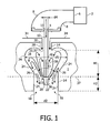
- Reference numeral 1 in Fig. 1 denotes a device for preparing a beverage suitable for human consumption and having a fine-bubble foam layer, such as coffee or milk with a fine-bubble foam layer.
- the device 1 is provided with a beverage unit 2 for delivering a beverage suitable for human consumption, coffee in this example, under pressure.
- the device 1 is further provided with a nozzle 4.
- An outlet 6 of the beverage unit 2 is connected to an inlet 10 of the nozzle 4 by means of a tube 8.
- the nozzle 4 is thus in fluid communication with the beverage unit 2 for the delivery of the beverage to the nozzle 4.
- the nozzle 4 thus generates a jet 12 of beverage.
- the device 1 is further provided with a receiving unit 14 into which the jet 12 is directed so as to obtain the beverage with a fine-bubble foam layer.
- the receiving unit 14 is provided with a chamber 16 which comprises at least one drain opening 18 for delivering the beverage with the fine-bubble foam layer.
- the receiving unit 14 is further provided with a jet impact member 20 that is at least partly accommodated in the chamber 16.
- the jet impact member 20 has a top 22 which lies free from an inner wall 24 of the chamber and which is accommodated inside the chamber.
- the nozzle 4 and the jet impact member 20 are mutually oriented such that the jet 12 hits against at least a portion of the top 22 of the jet impact member 20, such that the beverage 26 after hitting the jet impact member leaves the chamber through the at least one drain opening in the form of the beverage with the fine-bubble foam layer.
- air has been beaten into the beverage in the chamber 16 in such a manner that a beverage with a fine-bubble foam layer is obtained.
- the jet 12 in this example When hitting against the top 22 of the jet impact member 20, the jet 12 in this example will form a mist and/or turbulence of the beverage which flows against and/or along the inner wall 24 of the chamber 16 and subsequently leaves the chamber through the drain opening 18 as the beverage with the fine-bubble foam layer. It is achieved that the jet, when hitting against the top 22, forms a mist and/or turbulence of beverage which flows against and/or along the inner wall 24 of the chamber 16 in that the strength of the jet and the size of the chamber are mutually attuned. The jet must be sufficiently forceful and/or the chamber must be sufficiently small.
- the drain opening 18 in this example has a diameter of 5 mm, with the result that the chamber 16 is empty within a few seconds. A long period (tens of seconds) during which the chamber 16 empties itself, including final dripping, does not occur here.
- the receiving unit 14 in this example is provided with a channel 28 with an inlet opening 30 and an outlet opening 32.
- the outlet opening 32 in this example forms a product feed opening of the chamber 16 for the supply of the jet 12 to the chamber 16.
- the nozzle 4 in this example is at some distance from the inlet opening 30 of the channel 28.
- the jet 12 also sucks air 34 through the inlet opening 30 of the channel 28 into the chamber 16 during operation.
- the product feed opening 32 of the chamber 16 here at the same time acts as an air supply opening 32'.
- mist particles thus arises in the chamber, which mist particles will still be able to flow against and/or along the inner wall 24.
- the force of gravity will then cause the mist particles to move downward.
- the mist particles subsequently form a liquid beverage again, into which air has been introduced such that a fine-bubble foam layer is formed, which beverage can subsequently leave the chamber 16 through the drain opening 18.
- the beverage is now ready for consumption.
- the top 22 of the jet impact member 20 is present between the air supply opening 32' and the drain opening 18. Furthermore, the top 22 is directed towards the nozzle 4. In this example, the top 22 is also located between the product feed opening 32 and the drain opening 18. It holds in particular that the top 22 is directed towards the product feed opening 32.
- a surface of the top 22 is convex in shape. It is found in this case that the mist particles formed after the impact initially move upwards distributed over a solid angle ⁇ .
- a line 38 perpendicular to the surface 36 of the top 22 in a position where the jet 12 hits the top 22 is at least substantially parallel to the jet 12. Furthermore, a perpendicular line 38 in the center of the surface 36 of the top 22 is at least substantially directed towards the nozzle 4 and towards the product feed opening 32. This perpendicular line, too, is at least substantially parallel to the jet. Moreover, a line 38 perpendicular to the surface 36 of the top 22 in the position where the jet 12 is incident is directed towards the product feed opening 32, and also towards the nozzle in this example. It is also true that the top 22 is in the center of the chamber 16, viewed in a plane 37 perpendicular to the jet.
- the inner wall 24 of the chamber 16 in this example is at least substantially rotationally symmetrical with respect to an axis of rotation 40.
- This axis in addition extends in a longitudinal direction of the chamber. Said center is a point of this axis of rotation 40 in this example.
- the jet impact member 20 in this example is in a lower portion of the chamber 16.
- the top is also present on the axis 40 of the chamber.
- the jet impact member 20 has a pole construction in this example.
- An axial direction of the pole-shaped member extends in a longitudinal direction of the chamber 16.
- the axis of rotation 40 mentioned above extends through the top 22.
- a rotationally symmetrical receiving unit 14 is thus obtained around the symmetrical axis of rotation 40 in this example.
- the distance H1 from the product feed opening 32 to the top 22 is greater than the distance H2 from the top 22 to the drain opening 18 of the chamber 16. Also, in this example, H2 is greater than zero. Since the mist flow is especially formed in the chamber 16 between the top 22 and the product feed opening 32, a major portion of the chamber 16 can now be utilized for said laminar and/or turbulent flows of the mist.
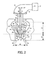
- reference numeral 1 denotes a first embodiment of a device according to the invention. Components corresponding to those of Fig. 1 have been given the same reference numerals. Since the device of Fig. 2 largely corresponds to the device of Fig. 1 , it is especially the differences between the devices of Figs. 1 and 2 that will be discussed below.
- the product feed opening 32 of the chamber in the device of Fig. 2 does not act as an air supply opening.
- the channel 28 here extends up to the nozzle 4.
- the air supply opening 32' is omitted.
- the device is constructed such that air 34 can be supplied to the chamber 16 exclusively through the at least one drain opening 18. It is found that a beverage with a fine-bubble foam layer is obtained by means of the device of Fig. 2 with properties comparable to those of the beverage with the fine-bubble foam layer obtained with the device of Fig. 1 . Since the air supply opening 32' can now be dispensed with, the device of Fig. 2 can be economically manufactured, if so desired.
- the nozzle 4 in this example is connected to the chamber via a fluid path extending from the nozzle to the product feed opening 32, which fluid path, formed by the channel 28 in this example, forms a closure for the outside air, with the result that in this example the air 34 can only be supplied to the chamber 16 through the at least one drain opening 18.
- the air will be sucked on in this example in that the beverage with the fine-bubble foam layer leaving the chamber 16 through the drain opening causes an air flow which leaves the chamber through the drain opening. This causes an underpressure in the chamber, with the result that at the same time air 34 is sucked into the chamber through the drain opening 18. This air flow accordingly compensates for the lost air carried along by the beverage when the latter leaves the chamber through the drain opening.
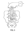
- a cross-section of the chamber 16 is substantially heart-shaped. This, however, is not essential. This may be illustrated, for example, with reference to Fig. 3 .
- FIG. 3 Components in Fig. 3 corresponding to those in Fig. 2 have been given the same reference numerals.
- An inner wall 24 of the chamber 16 in Fig. 3 is now substantially cylindrical in shape for the major part.
- the surface 36 of the top 22 is of planar construction in this example.
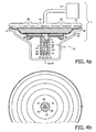
- Figs. 4a and 4b show an alternative embodiment of a device according to the invention.
- the device is provided with a unit 42 which comprises a receiving unit 14. Components of the receiving unit 14 corresponding to those of Figs. 2 and 3 have been given the same reference numerals as in Figs. 2 and 3 .
- the unit 42 is furthermore provided with the nozzle 4.
- the unit 42 comprises a holder 44 for accommodating a pad 46 filled with a product to be extracted and/or dissolved, such as ground coffee and/or a dairy creamer.
- the holder 44 and the pad 46 may be of a type as described in European patent 904.717 .
- the holder 44 is provided with a bowl-shaped inner space 47 which is bounded by a bottom 48 and an upright side wall 50.
- the upright side wall 50 extends around the bottom.
- the bottom and the upright side wall thus define a bowl-shaped inner space of the holder in which the pad is accommodated during use.
- the pad 46 extends over the bottom 48 up to the upright side wall 50.
- At least one drain opening, formed by the nozzle 4 in this example, is provided in the bottom 48. This drain opening forms an outlet of the holder.
- the inlet 10 of the nozzle in this example is accordingly in fluid communication with the outlet of the holder, because the inlet 10 and an outlet 11 of the nozzle constitute the outlet of the holder. In this example, moreover, grooves are provided in the bottom of the holder.
- the device 1 is further provided with a lid 52 with which the holder can be closed off.
- the device 1 also comprises a hot-water unit 54 for supplying hot water under pressure to an inner space of the lid 52.
- the lid 52 is provided with a number of outlet openings 56 at its lower side. Hot water is thus supplied through the outlet openings 56 at an upper side of the holder 44 during operation.
- the holder 44 and the hot-water unit 54 together form the beverage unit 2 of Figs. 2 and 3 . It further holds in this example that the receiving unit 14 and the holder 44 are mechanically interconnected.
- the nozzle 4 is mechanically connected to the holder 44.
- the nozzle 4, holder 44, and receiving unit 14 thus form a mechanical unit.
- the air 34 again flows through the drain opening 18 into the chamber 16.
- the jet impact member 20 in this example is connected to the chamber 16 by means of three lateral arms 60.
- the pad 46 extends over the bottom 48 of the holder 44 up to the upright side walls 50 of the holder.
- the assembly of the pad 46 and the unit 42 also forms part of the invention.
- the device of Figs. 4a and 4b operates as follows.
- the hot-water unit 54 supplies hot water under pressure to the inner space of the lid 52.
- This hot water leaves the lid 52 under pressure through the outlet openings 56 of the lid 52.
- Hot water is thus supplied to the upper side of the holder 44.
- This water is pressed through the pad 46, which is filled with ground coffee in this example.
- a coffee extract is formed thereby which leaves the holder 44 through the nozzle 4. Since the coffee extract is supplied to the nozzle 4 under pressure, a jet of beverage is now formed.
- This jet 12 hits against the top 22 of the jet impact member 20 as discussed with reference to Figs. 2 and 3 .
- Air is supplied to the chamber 16 exclusively through suction of air via the drain opening 18.
- the beverage with the fine-bubble foam layer in this example the coffee extract with the fine-bubble foam layer, leaves the chamber 16 through the drain opening 18.
- the drain opening 18 in this example is formed by the openings formed between the lateral arms 60.
- Figs. 5a and 5b show a fourth embodiment of a device according to the invention. Components corresponding to those of Fig. 4 have been given the same reference numerals.
- the holder, the receiving unit comprising the chamber 16 and the jet impact member 20, and the nozzle 4 are mechanically interconnected into one unit 42.
- a first pad 46.1 is accommodated in the holder 44 in this example, resting on the bottom 48.
- a second pad 46.2 is present above the first pad 46.1, resting substantially on the first pad 46.1.
- the first pad 46.1 again comprises an envelope made of filter paper which in this example is filled with a soluble substance.
- the soluble substance in this example is a dairy creamer.
- the second pad 46.2 is also provided with an envelope of filter paper which in this example is filled with a product to be extracted.
- the product in this case is ground coffee.
- the first pad 46.1 to be filled with a soluble product
- the second pad 46.2 to be filled with a product to be extracted.
- both the first and/or the second pad may be filled with a product to be extracted as well as a product to be dissolved.
- the chamber 16 is provided with a product feed opening 32 through which the jet generated by a nozzle 4 is supplied to the chamber during operation. More in particular, the product feed opening 32 is formed by the nozzle 4 in this example.
- a space 60' within the chamber between the nozzle 4 and the jet impact member 20 is free from restrictions for a flow of the beverage between the nozzle and the jet impact member. This is in contrast to the device of Figs. 2 , 3 , and 4 , in which the channel 28 may be denoted a restriction.
- Hot water is supplied to the lid 52 by the hot-water unit 54 during operation.
- This hot water is supplied under pressure through the openings 56 in the lid 52 to an upper side of the holder 44.
- This hot water will thus be pressed through the coffee pad 46.2.
- the coffee extract subsequently leaves the coffee pad at the lower side thereof and enters the milk pad 46.1.
- the dairy creamer present in the milk pad 46.1 will subsequently dissolve in the coffee extract.
- the coffee extract with the dairy creamer dissolved therein is subsequently supplied under pressure to the nozzle 4.
- a jet 12 of the beverage is created thereby which hits against the top of the jet impact member 20.
- the beverage with the fine-bubble foam layer, cappuccino in this example will subsequently flow from the drain opening 18, exactly as in the examples described above. Air 34 will be supplied through this drain opening to the chamber, as discussed above.
- Figs. 6a and 6b relate to a fifth embodiment of a device according to the invention.
- This device largely corresponds to the device of Figs. 5a and 5b .
- the holder 44 now accommodates a pad 46 filled with ground coffee.
- the jet impact member is provided with an air supply channel 62 which extends from the exterior through the jet impact member into the chamber 16.
- the air supply channel comprises an inlet 63 situated outside the chamber. More in particular, two air supply openings 64.1 and 64.2 are provided in a side wall of the jet impact member, which openings are in fluid communication with the air supply channel 62.
- air from outside the chamber
- air will only be supplied to the chamber 16 through the air supply channel 62 and (in this example also) via the drain opening 18. Air thus flows through the inlet 63 into the air supply channel and then enters the chamber through the air supply opening 64.
- the side wall of the jet impact member may be provided with different numbers of air supply openings 64. What is relevant in this example is that it is provided with at least one air supply opening.
- the supply of air through the air supply channel 62 takes place exactly as discussed above. Since the beverage 26 with the fine-bubble foam layer flows from the chamber through the drain opening, an underpressure is created in the chamber 16 whereby air 34 is sucked on through the air supply channel 62 and through the drain opening 18.
- Figs. 7a and 7b show a sixth embodiment of a device according to the invention. This corresponds at least substantially to the embodiment of Figs. 5a and 5b .
- a difference is again that only one pad is accommodated in the holder 44 in the form of a coffee pad as discussed with reference to Figs. 6a and 6b .
- Another difference with the device of Figs. 5a and 5b is that the jet impact member 20 is not connected to the chamber 16.
- the holder 44, the nozzle 4, and the chamber 16 are mechanically interconnected in this example so as to form a unit 42'. This unit 42' rests, for example, on support means 65 of the device.
- the unit 42' can be lifted from a portion 66 of the device to which the jet impact member 20 is fixedly connected.
- the portion 66 of the device may additionally be provided with an inlet opening 68, while the jet impact member 20 is connected to said portion 66 of the device by means of lateral arms as discussed with reference to Figs. 4a and 4b .
- a lower side 69 of the chamber 16 also lies free from the portion 66 of the device.
- the operation of the device of Figs. 7a and 7b is fully similar to what was discussed with reference to Figs. 5 and 6 .
- the beverage leaving the drain opening 18 can flow away through the opening 68 in the device and/or through an intermediate space 70 between a lower side 69 of the chamber 16 and the portion 66 of the device.
- Air can be supplied to the chamber 16 exclusively through the drain opening 18 of the chamber. This air is then supplied to the drain opening 18 of the chamber via the opening 68 and/or via the intermediate space 70 between the chamber and the portion 66 of the device.
- the lower side 69 of the chamber will bear on the portion 66 of the device during operation, in which case the space 70 between the lower side 69 of the chamber and the portion 66 of the device is absent.
- the beverage 26 flowing through the drain opening can flow away through the opening 68 in the portion 66 of the device. In that case air can only be supplied through the opening 68 and subsequently through the drain opening 18 to the chamber 16.
- Figs. 8a and 8b show a seventh embodiment of a device according to the invention. Again, components corresponding to those of Figs. 2 to 6 have been given the same reference numerals. It is again true in the device of Figs. 8a and 8b that the device is provided with a mechanical unit 42' composed of the holder 44, the nozzle 4, and the chamber 16. The jet impact member 20 again does not form part of this mechanical unit 42' and is fixedly connected to another portion 66 of the device. The jet impact member 20 in this example is again provided with an air supply channel extending through the jet impact member into the chamber 16. The preparation of the beverage takes place entirely as discussed above. The finished beverage 26 will again leave the chamber through the drain opening 18.
- the beverage now flows away through the intervening space 70 between the lower side 69 of the chamber 16 and the portion 66 of the device.
- Air is supplied to the chamber only through the air supply channel 62 and possibly in this example also, though to a lesser extent, through the at least one drain opening 18.
- a plurality of jets may impact on the jet impact member 20 instead of one jet.
- a plurality of nozzles 4, each directing a jet towards the jet impact member 20, may then be used.
- the nozzle 4 may be provided with a plurality of outlets for generating a plurality of jets.
- the plurality of jets may also be incident on a plurality of jet impact members accommodated in the chamber 16.
- the plurality of jets may alternatively be incident on one jet impact member.
- the chamber is provided with a plurality of jet impact members 20 which are each hit by at least one jet originating from, for example, a plurality of nozzles or a single nozzle.
- the jet impact member may have the shape of a planar plate, as was stated above.
- the top 22 may alternatively be convex as shown in Fig. 2 , while holes running from top to bottom are provided in the top 22 adjacent an edge 23.
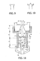
- the top 22 may also be concave, see Fig. 9 .
- the top 22 may be concave along its outer circumference with a tip in the center, see Fig. 10 .
- the receiving unit 14 may also be constructed as shown in Fig. 11 .
- the jet impact member may be replaced by a cylinder or tube in the device of Figs.
- the diameter of the cylinder or tube may be, for example, equal to the diameter of the top in Figs. 2 to 8 and 11 .
- the nozzle may alternatively be formed, for example, by a nozzle as described in EP 1 092 377 .
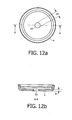
- the nozzle may also be formed by a plate with an opening as shown in Figs. 12a and 12b .
- the thickness b of the plate is, for example, 0.1 to 0.5 mm, preferably 0.2 to 0.4 mm.
- the diameter of the jet when issuing from the nozzle may vary, for example, from 0.2 to 1.6 mm, more in particular from 0.4 to 1.4 mm, preferably from 0.6 to 1 mm, and more preferably from 0.7 to 0.9 mm. This diameter is approximately 0.8 mm in the present example.
- the diameter of the top may vary, for example, from 1.4 mm to 10 mm, more in particular from 1.5 mm to 8 mm, preferably from 1.75 mm to 5 mm, and more preferably from 1.75 to 3.0 mm. This diameter is 2 mm in the example.
- the diameter of the chamber at the area of the top (for example d2 in Figs. 3 and 4 ) divided by the diameter of the top (for example d3 in Figs. 3 and 11 ) is, for example, greater than 1.1, preferably greater than 1.2, and more preferably greater than 2.0. Said ratio is preferably approximately equal to 2.5.
- the ratio d2/d3 determines the extent of the outflow of the beverage. When this ratio is increased, more space is created for the supply of air, which leads to a coarser foam. When the diameter d2 remains the same and d3 is made greater, for example, the foam becomes finer.
- the ratio d2/d3 could be made variable in that the diameter d2 and/or the diameter d3 is made adjustable in a known manner.
- This adjusting possibility may also be achieved by means of a ring closed around the jet impact member, so that the diameter d3 is increased, or a ring fastened against the inner wall of the chamber, so that the diameter d2 is decreased.
- Various rings may thus lead to various diameters d2 and/or d3.
- the surface area through which the beverage can flow out will also be reduced if the jet impact member increases in diameter from the top in a direction towards the drain opening inside the chamber.
- the supply of air need not be affected thereby if the jet impact member is provided with said air supply channel.
- the surface roughness of the jet impact member and/or the inner wall may be varied.
- a comparatively smooth surface for example, could yield a finer foam than a surface that is comparatively rough.
- the chamber 16 need not be cylindrical or rotationally symmetrical, it may have alternative shapes.
- a cross-section of the chamber perpendicular to the axis 40 may have, besides a circular shape, a triangular, rectangular, square, or any other, non-symmetrical shape.
- the jet impact member 20 is in the center of the chamber 16 in the examples given. It is also conceivable, however, that the axis 40 of the chamber does not coincide with a center of the top of the jet impact member. It is accordingly also possible that the jet impact member, viewed in a plane perpendicular to the axis 40 of the chamber, is positioned out of center in the chamber, as long as the jet hits the jet impact member. In other words, the distance between the jet impact member and the chamber wall may vary.
- the chamber may also have a non-rotationally-symmetrical shape in this case, as discussed above.
- said ratio may be, for example, smaller than 5. Said ratio may vary from 1.1 to 5, preferably from 1.5 to 4, and more preferably from 1.75 to 3.
- the top of the jet impact member may be made, for example, from POM, PP, ABS, or metal.
- the diameter d4 of the opening (inlet) 10 of the nozzle may vary, for example, from 0.3 to 1.5 mm, preferably from 0.6 to 1.0 mm, and more preferably from 0.7 to 0.9 mm.
- the term "nozzle" is understood to denote any means for generating a jet.
- a greatest diameter d5 of the chamber may be, for example, 1 to 4 times greater, preferably 1 to 3 times greater than the diameter d2 of the chamber at the area of the top (cf., for example, Fig. 2 ).
- a diameter of the drain opening 18 of the chamber may vary, for example, from 3 mm to 15 mm, preferably from 2.5 mm to 8 mm, and more preferably from 4 mm to 6 mm.
- the orientation of the devices of Figs. 2 to 12 is not relevant.
- the device of Fig. 4 may be tilted or even placed upside-down.
- the construction of the system will obviously have to be adapted in that case, as will be evident to those skilled in the art.
- the beverage supplied to the nozzle may also comprise a concentrate that is yet to be diluted with water after delivery by the device.
- the beverage suitable for consumption in that case is a concentrate yet to be diluted.
- the holders 44 discussed above may alternatively be provided with a filter bottom which is known per se, so that the holders 44 may be filled with loose products to be extracted, such as coffee and/or tea and/or other loose products to be dissolved such as a dairy creamer.
- a product to be dissolved in the present application is also deemed to denote other products such as a product for the preparation of cocoa and flavoring agents.
- a product to be extracted may also be a product other than coffee or tea.
Claims (16)
- Vorrichtung (1) zur Zubereitung eines für den menschlichen Verzehr geeigneten Getränks (26) mit einer feinblasigen Schaumschicht, wie zum Beispiel Kaffee oder Milch mit einer feinblasigen Schaumschicht, versehen mit einer Getränkeeinheit (2, 42, 42'), um das Getränk unter Druck bereitzustellen, mindestens einer Düse (4), die in Flüssigkeitsverbindung mit der Getränkeeinheit (2, 42, 42') steht, um das Getränk der Düse (4) so zuzuführen, dass letztere einen Strahl (12) des Getränks erzeugen kann, sowie einer Aufnahmeeinheit (14), in die der Strahl (12) zur Aufnahme des Getränks (26) mit der feinblasigen Schaumschicht gelenkt wird, wobei die Aufnahmeeinheit (14) mit einer Kammer (16), die mindestens eine Ablauföffnung (18) zur Abgabe des Getränks (26) mit der feinblasigen Schaumschicht aufweist, sowie einem Strahlaufprallelement (20), das in der Kammer (16) aufgenommen ist und eine Oberseite (22) aufweist, die von einer Innenwand (24) der Kammer (16) frei liegt, versehen ist, dadurch gekennzeichnet, dass die Vorrichtung (1) so aufgebaut ist, dass der Kammer (16) Luft ausschließlich durch die mindestens eine Ablauföffnung (18) und/oder durch einen Lufteinlasskanal (62), der sich durch das Strahlaufprallelement (20) in die Kammer (16) erstreckt, zugeführt wird, und dass die Düse (4) und das Strahlaufprallelement (20) so zueinander ausgerichtet sind, dass der Strahl (12) gegen zumindest einen Teil der Oberseite (22) des Strahlaufprallelements (20) trifft, so dass das Getränk nach Auftreffen auf das Strahlaufprallelement (20) einen feinen Nebel des Getränks bildet, der gegen die und/oder entlang der Innenwand (24) der Kammer (16) fließt und anschließend die Kammer (16) durch die mindestens eine Ablauföffnung (18) in Form des Getränks (26) mit der feinblasigen Schaumschicht verlässt.
- Vorrichtung (1) nach Anspruch 1, dadurch gekennzeichnet, dass die Kammer (16) mit einer Produktzuführungsöffnung (4, 32) versehen ist, durch die der von der Düse (4) erzeugte Strahl (12) während des Gebrauchs der Kammer (16) zugeführt wird.
- Vorrichtung (1) nach Anspruch 2, dadurch gekennzeichnet, dass die Produktzuführungsöffnung (4, 32) durch die Düse (4) gebildet wird.
- Vorrichtung (1) nach Anspruch 3, dadurch gekennzeichnet, dass ein Zwischenraum (60') innerhalb der Kammer (16) zwischen der Düse (4) und dem Strahlaufprallelement (20) frei von Einschränkungen ist, die einen Durchfluss des Getränks zwischen der Düse (4) und dem Strahlaufprallelement (20) behindern.
- Vorrichtung (1) nach einem der Ansprüche 2 bis 4, dadurch gekennzeichnet, dass die Oberseite (22) des Strahlaufprallelements (20) zwischen der Produktzuführungsöffnung (4, 32) und der Ablauföffnung (18) vorgesehen ist.
- Vorrichtung (1) nach einem der Ansprüche 2 bis 5, dadurch gekennzeichnet, dass die Oberseite (22) zumindest im Wesentlichen auf die Produktzuführungsöffnung (4, 32) gerichtet ist.
- Vorrichtung (1) nach einem der vorangegangenen Ansprüche, dadurch gekennzeichnet, dass das Strahlaufprallelement (20) durch mindestens einen lateralen Arm (60) mit der Kammer (16) verbunden ist.
- Vorrichtung (1) nach einem der vorangegangenen Ansprüche, dadurch gekennzeichnet, dass die Getränkeeinheit (42, 42') mit einem Einsatz (44) zur Aufnahme eines zu extrahierenden und/oder zu lösenden Produkts, wie z.B. Kaffee, Tee, und/oder eines Kaffeeweißers auf Milchbasis, sowie mit einer Heißwassereinheit (54) zum Zuführen von heißem Wasser zu dem Einsatz (44) versehen ist, um das Getränk, das an die Düse (4) abgegeben wird, zu erhalten.
- Vorrichtung (1) nach Anspruch 8, dadurch gekennzeichnet, dass die Kammer (16) und die Düse (4) mit dem Einsatz (44) verbunden sind.
- Vorrichtung (1) nach Anspruch 9, dadurch gekennzeichnet, dass die Kammer (16) und die Düse (4) mit dem Einsatz (44) integriert sind.
- Vorrichtung (1) nach Anspruch 10, dadurch gekennzeichnet, dass das Strahlaufprallelement (20) ebenfalls mit dem Einsatz (44) integriert ist.
- Verfahren zur Zubereitung eines für den menschlichen Verzehr geeigneten Getränks (26) mit einer feinblasigen Schaumschicht, wie zum Beispiel Kaffee oder Milch, wobei in dem Verfahren ein das Getränk enthaltender Flüssigkeitsstrahl (12) erzeugt und der Flüssigkeitsstrahl (12) einer Aufnahmeeinheit (14) so zugeführt wird, dass der Strahl (12) in die Aufnahmeeinheit (14) unter Druck eintritt, um das Getränk (26) mit der feinblasigen Schaumschicht zu erhalten, wobei die Aufnahmeeinheit (14) mit einer Kammer (16), die mindestens eine Ablauföffnung (18) zur Abgabe des Getränks (26) mit der feinblasigen Schaumschicht aufweist, sowie einem Strahlaufprallelement (20), das in der Kammer (16) aufgenommen ist und eine Oberseite (22) aufweist, die von einer Innenwand (24) der Kammer (16) frei liegt, versehen ist, wobei der Strahl (12) so gelenkt wird, dass er gegen einen Teil der Oberseite (22) des Strahlaufprallelements (20) trifft, und wobei das Getränk nach Auftreffen auf das Strahlaufprallelement (20) als das Getränk (26) mit der feinblasigen Schaumschicht durch die mindestens eine Ablauföffnung (18) aus der Kammer (16) austritt, dadurch gekennzeichnet, dass der Kammer (16) Luft (34) ausschließlich durch die mindestens eine Ablauföffnung (18) und/oder durch einen Lufteinlasskanal (62), der sich durch das Strahlaufprallelement (20) in die Kammer (16) erstreckt, zugeführt wird, und dass der Strahl (12), nachdem er gegen das Strahlaufprallelement (20) trifft, einen feinen Nebel des Getränks bildet, der gegen die und/oder entlang der Innenwand (24) der Kammer (16) fließt und anschließend die Kammer (16) durch die mindestens eine Ablauföffnung (18) in Form des Getränks (26) mit der feinblasigen Schaumschicht verlässt.
- Einheit (42), die mit einer Aufnahmeeinheit (14) und einer Düse (4) der Vorrichtung (1) nach einem der Ansprüche 1 bis 11 sowie einem Einsatz (44) zur Aufnahme eines zu extrahierenden und/oder zu lösenden Produkts, wie z.B. Kaffee, Tee, und/oder eines Kaffeeweißers auf Milchbasis, versehen ist, wobei der Einsatz (44), die Kammer (16), das Strahlaufprallelement (20) und die Düse (4) miteinander mechanisch verbunden sind, und wobei der Einsatz (44) mindestens einen Auslass (6) umfasst, der in Flüssigkeitsverbindung mit einem Einlass (10) der Düse (4) steht.
- Einheit (42) nach Anspruch 13, dadurch gekennzeichnet, dass der Einsatz (44) mit einem Boden (48) und einer aufrechten Seitenwand (50) versehen ist, die sich um den Boden (48) erstreckt, wobei der Boden (48) den mindestens einen Auslass (6) umfasst.
- Einheit (42) nach Anspruch 13 oder 14, dadurch gekennzeichnet, dass der Einsatz (44) so ausgeführt ist, dass er mit mindestens einem Pad (46, 46.1, 46.2) gefüllt wird, das eine Umhüllung aus Filterpapier umfasst und das mit dem zu extrahierenden und/oder zu lösenden Produkt gefüllt ist.
- Anordnung aus einer Einheit (42) nach einem der Ansprüche 13 bis 15 und mindestens einem Pad (46, 46.1, 46.2), das eine Umhüllung aus Filterpapier umfasst und das mit dem zu extrahierenden und/oder zu lösenden Produkt gefüllt ist, wobei das Pad (46, 46.1, 46.2) in dem Einsatz (44) aufgenommen wird und sich darin über einem Boden (48) des Einsatzes (44) bis zu einer aufrechten Seitenwand (50) des Einsatzes (44) erstreckt.
Priority Applications (1)
| Application Number | Priority Date | Filing Date | Title |
|---|---|---|---|
| EP04801540A EP1694180B1 (de) | 2003-12-11 | 2004-12-10 | Vorrichtung zur zubereitung eines für den menschlichen verzehr geeigneten getränks mit einer schaumlage aus feinen bläschen |
Applications Claiming Priority (3)
| Application Number | Priority Date | Filing Date | Title |
|---|---|---|---|
| EP03104653 | 2003-12-11 | ||
| EP04801540A EP1694180B1 (de) | 2003-12-11 | 2004-12-10 | Vorrichtung zur zubereitung eines für den menschlichen verzehr geeigneten getränks mit einer schaumlage aus feinen bläschen |
| PCT/IB2004/052759 WO2005058109A1 (en) | 2003-12-11 | 2004-12-10 | Device for preparing a beverage suitable for human consumption with a fine-bubble foam layer |
Publications (2)
| Publication Number | Publication Date |
|---|---|
| EP1694180A1 EP1694180A1 (de) | 2006-08-30 |
| EP1694180B1 true EP1694180B1 (de) | 2013-02-20 |
Family
ID=34684574
Family Applications (1)
| Application Number | Title | Priority Date | Filing Date |
|---|---|---|---|
| EP04801540A Active EP1694180B1 (de) | 2003-12-11 | 2004-12-10 | Vorrichtung zur zubereitung eines für den menschlichen verzehr geeigneten getränks mit einer schaumlage aus feinen bläschen |
Country Status (6)
| Country | Link |
|---|---|
| US (3) | US7779749B2 (de) |
| EP (1) | EP1694180B1 (de) |
| JP (1) | JP5000304B2 (de) |
| CN (1) | CN1889875B (de) |
| ES (1) | ES2405847T3 (de) |
| WO (1) | WO2005058109A1 (de) |
Families Citing this family (34)
| Publication number | Priority date | Publication date | Assignee | Title |
|---|---|---|---|---|
| NL1020836C2 (nl) | 2002-06-12 | 2003-12-15 | Sara Lee De Nv | Inrichting en werkwijze voor het bereiden van koffie met een fijnbellige schuimlaag, in het bijzonder cappuccino. |
| NL1020833C2 (nl) | 2002-06-12 | 2003-12-15 | Sara Lee De Nv | Inrichting voor het bereiden van een voor consumptie geschikte drank met een fijnbellige schuimlaag. |
| CN1889875B (zh) * | 2003-12-11 | 2010-06-23 | 皇家飞利浦电子股份有限公司 | 用于制备带有细泡式泡沫层的适于人消费的饮料的装置 |
| NL1026834C2 (nl) | 2004-08-12 | 2006-02-14 | Sara Lee De Nv | Bereiden van thee met behulp van een theepad en een koffiezetapparaat. |
| NL1029503C2 (nl) * | 2005-07-12 | 2007-01-15 | Sara Lee De Nv | Systeem en werkwijze voor het bereiden van een voor consumptie geschikte drank, alsmede een gebruik van een dergelijk systeem, een opvangkamer en een houder. |
| US20070028783A1 (en) * | 2005-08-02 | 2007-02-08 | Chen Yee M | Brewing apparatus for preparing foam, froth, or crema under low pressure |
| US20070259092A1 (en) * | 2005-08-02 | 2007-11-08 | Chen Yee M | Brewing apparatus for preparing foam, froth, or crema under low pressure |
| NL2000494C2 (nl) * | 2006-03-21 | 2009-01-20 | Dong-Lei Wang | Schuiminrichting in een koffiemachine. |
| NL1031614C2 (nl) * | 2006-04-18 | 2007-10-19 | Nova Products B V | Werkwijze, inrichting en inzetstuk voor het vervaardigen van koffie met geschuimde melk. |
| DE202006008409U1 (de) * | 2006-05-27 | 2006-08-10 | Eugster/Frismag Ag | Einrichtung zum selbsttätigen Auflösen von Instantpulver, insbesondere Milchpulver, in heißem Wasser und insbesondere zum Aufschäumen |
| NL2000218C2 (nl) * | 2006-09-07 | 2008-03-12 | Bravilor Holding Bv | Bereidingsinrichting. |
| CN101686776A (zh) * | 2007-02-16 | 2010-03-31 | 皇家飞利浦电子股份有限公司 | 控制液体流过加热器 |
| WO2009008700A1 (en) * | 2007-07-12 | 2009-01-15 | Meccano Asia Ltd. | Device and method for the preparation of a frothy liquid for human consumption |
| DE102007047649A1 (de) * | 2007-10-05 | 2009-04-09 | BSH Bosch und Siemens Hausgeräte GmbH | Heißwasserauslauf |
| EP2510803B2 (de) | 2008-01-29 | 2019-12-11 | Koninklijke Douwe Egberts B.V. | System zur Herstellung eines Getränks |
| GB2475291B (en) | 2009-11-12 | 2012-03-28 | Kraft Foods R & D Inc | Beverage preparation machines |
| GB2475290A (en) * | 2009-11-12 | 2011-05-18 | Kraft Foods R & D Inc | Nozzle for beverage preparation machines |
| BR112012032015B1 (pt) * | 2010-06-18 | 2020-04-14 | Koninl Philips Electronics Nv | dispositivo para espumar um líquido e aparelho |
| CN201958642U (zh) * | 2011-01-30 | 2011-09-07 | 漳州灿坤实业有限公司 | 一种咖啡起泡装置 |
| DE202011110158U1 (de) * | 2011-07-29 | 2012-12-20 | Volker Barth | Vorrichtung zum Schäumen einer Flüssigkeit |
| GB2494464B (en) * | 2011-09-12 | 2014-12-03 | Kraft Foods R & D Inc | Improvements in and relating to beverage preparation machines |
| DE102013105620A1 (de) * | 2012-06-01 | 2013-12-05 | Mattel, Inc. | Rennstreckenspielsatz für schwimmende Spielzeugfahrzeuge |
| CA2939341A1 (en) * | 2014-02-14 | 2015-08-20 | Remington Designs, Llc | Beverage brewer and related methods for brewing beverages |
| NL1040942B1 (nl) | 2014-09-08 | 2016-09-27 | Innobizzer B V | Systeem met regelbare luchtinlaat en werkwijze voor het vervaardigen van een warme drank. |
| JP6456490B2 (ja) * | 2014-09-29 | 2019-01-23 | コーニンクレッカ フィリップス エヌ ヴェKoninklijke Philips N.V. | ディスペンサ用の消耗品及びディスペンサ用の処理ユニット |
| CN107205578B (zh) | 2014-11-20 | 2020-11-24 | 皇家戴维艾格伯茨有限公司 | 制备咖啡饮料的装置、系统及相关使用和相关方法 |
| JP6656252B2 (ja) * | 2014-12-15 | 2020-03-04 | コーニンクラケ ダウ エグバート ビー.ブイ. | 飲料摂取物を調製するためのユニット、装置、およびシステム |
| DE102016102795B4 (de) * | 2016-02-17 | 2017-10-19 | Dhp Gastronomie Gmbh | Filterelement und Milchaufschäumer mit einem Filterelement |
| US20170318999A1 (en) * | 2016-05-05 | 2017-11-09 | Teforia Company | Apparatus for Brewing a Beverage |
| AT518804B1 (de) * | 2016-06-21 | 2018-07-15 | Mock Herbert | Verfahren und Vorrichtung zum Aufbringen von dekorativen Darstellungen auf einer mehrschichtigen Oberfläche von Kaffee |
| JP6791685B2 (ja) * | 2016-09-01 | 2020-11-25 | ツインバード工業株式会社 | コーヒーメーカー |
| ES2907218T3 (es) * | 2016-11-16 | 2022-04-22 | Nestle Sa | Aparato de preparación de bebidas que comprende una cámara de mezcla |
| NL2018027B1 (en) * | 2016-12-20 | 2018-06-28 | Douwe Egberts Bv | Drainage connector unit and assembly for the drainage of liquid waste of beverage dispensing devices |
| DE102017213603B4 (de) * | 2017-08-04 | 2020-01-02 | BSH Hausgeräte GmbH | Crema-Aufschäumer |
Family Cites Families (12)
| Publication number | Priority date | Publication date | Assignee | Title |
|---|---|---|---|---|
| NL1006039C2 (nl) * | 1997-05-13 | 1998-11-16 | Sara Lee De Nv | Inrichting voor het bereiden van koffie met een kleinbellige schuimlaag. |
| NL1007171C2 (nl) | 1997-09-30 | 1999-03-31 | Sara Lee De Nv | Samenstel voor gebruik in een koffiemachine voor het bereiden van koffie, houder en pouch van dat samenstel. |
| JP3498011B2 (ja) * | 1999-06-25 | 2004-02-16 | 富士電機リテイルシステムズ株式会社 | 発泡飲料ディスペンサの飲料注出バルブ |
| NL1013270C2 (nl) | 1999-10-12 | 2001-04-17 | Sara Lee De Nv | Inrichting voor het bereiden van een koffie-extract met een fijnbellige schuimlaag. |
| NL1016106C2 (nl) | 2000-09-05 | 2002-03-07 | Sara Lee De Nv | Inrichting voor het bereiden van een koffie-extract met een kleinbellige schuimlaag. |
| NL1019013C2 (nl) * | 2001-09-21 | 2003-03-26 | Sara Lee De Nv | Bereiding van cappuccino. |
| ITMI20012146A1 (it) * | 2001-10-17 | 2003-04-17 | De Longhi Spa | Dispositivo e procedimento per produrre schiuma in una coppetta di una macchina da caffe' |
| JP2003275102A (ja) * | 2002-03-27 | 2003-09-30 | Sanyo Electric Co Ltd | ミキシングボウルおよびこれを設けた飲料製造装置 |
| NL1020833C2 (nl) * | 2002-06-12 | 2003-12-15 | Sara Lee De Nv | Inrichting voor het bereiden van een voor consumptie geschikte drank met een fijnbellige schuimlaag. |
| DE20320605U1 (de) * | 2002-09-13 | 2004-10-21 | Koninklijke Philips Electronics N.V. | Padträger für eine Getränkemaschine, Schaumeinheit und Getränkemaschine mit einem derartigen Padträger zum Bereiten eines Getränkes mit einer Schaumeinheit unter Verwendung eines derartigen Padträgers |
| CN1889875B (zh) * | 2003-12-11 | 2010-06-23 | 皇家飞利浦电子股份有限公司 | 用于制备带有细泡式泡沫层的适于人消费的饮料的装置 |
| US7237475B2 (en) * | 2003-12-23 | 2007-07-03 | Electrical And Electronics, Limited | Cabinet design of filter holder for pressurized espresso machines |
-
2004
- 2004-12-10 CN CN200480036900.6A patent/CN1889875B/zh not_active Expired - Fee Related
- 2004-12-10 US US10/581,352 patent/US7779749B2/en not_active Expired - Fee Related
- 2004-12-10 EP EP04801540A patent/EP1694180B1/de active Active
- 2004-12-10 JP JP2006543710A patent/JP5000304B2/ja not_active Expired - Fee Related
- 2004-12-10 WO PCT/IB2004/052759 patent/WO2005058109A1/en active Application Filing
- 2004-12-10 ES ES04801540T patent/ES2405847T3/es active Active
-
2010
- 2010-06-04 US US12/793,736 patent/US8257768B2/en active Active
- 2010-06-04 US US12/793,746 patent/US8935977B2/en not_active Expired - Fee Related
Also Published As
| Publication number | Publication date |
|---|---|
| US8935977B2 (en) | 2015-01-20 |
| EP1694180A1 (de) | 2006-08-30 |
| US7779749B2 (en) | 2010-08-24 |
| JP5000304B2 (ja) | 2012-08-15 |
| US20100282092A1 (en) | 2010-11-11 |
| WO2005058109A1 (en) | 2005-06-30 |
| US20100278989A1 (en) | 2010-11-04 |
| JP2007513674A (ja) | 2007-05-31 |
| US20070079707A1 (en) | 2007-04-12 |
| CN1889875A (zh) | 2007-01-03 |
| US8257768B2 (en) | 2012-09-04 |
| CN1889875B (zh) | 2010-06-23 |
| ES2405847T3 (es) | 2013-06-04 |
Similar Documents
| Publication | Publication Date | Title |
|---|---|---|
| EP1694180B1 (de) | Vorrichtung zur zubereitung eines für den menschlichen verzehr geeigneten getränks mit einer schaumlage aus feinen bläschen | |
| US7748311B2 (en) | Apparatus for preparing a consumable beverage with a fine-bubbled foam layer | |
| US7958815B2 (en) | Beverage device for making a beverage with a foam layer on top | |
| EP1395155B1 (de) | Vorrichtung und verfahren zur herstellung von geschäumten getränken | |
| KR100782432B1 (ko) | 거친 충격 표면을 이용하여 미세-거품 포말층을 갖는 커피추출물을 제조하는 장치 | |
| US7698993B2 (en) | Apparatus and method for preparing a beverage fit for consumption with a fine-bubble froth layer | |
| JP4137884B2 (ja) | 細かい気泡の泡層を有するコーヒー、特にカプチーノを作成する装置および方法 | |
| US8549990B2 (en) | Coffeemaker comprising a foam-making device | |
| BR122014006071B1 (pt) | método para preparar uma bebida consumível com uma camada de espuma de bolha fina |
Legal Events
| Date | Code | Title | Description |
|---|---|---|---|
| PUAI | Public reference made under article 153(3) epc to a published international application that has entered the european phase |
Free format text: ORIGINAL CODE: 0009012 |
|
| 17P | Request for examination filed |
Effective date: 20060711 |
|
| AK | Designated contracting states |
Kind code of ref document: A1 Designated state(s): AT BE BG CH CY CZ DE DK EE ES FI FR GB GR HU IE IS IT LI LT LU MC NL PL PT RO SE SI SK TR |
|
| 17Q | First examination report despatched |
Effective date: 20061205 |
|
| DAX | Request for extension of the european patent (deleted) | ||
| GRAP | Despatch of communication of intention to grant a patent |
Free format text: ORIGINAL CODE: EPIDOSNIGR1 |
|
| GRAS | Grant fee paid |
Free format text: ORIGINAL CODE: EPIDOSNIGR3 |
|
| GRAA | (expected) grant |
Free format text: ORIGINAL CODE: 0009210 |
|
| AK | Designated contracting states |
Kind code of ref document: B1 Designated state(s): AT BE BG CH CY CZ DE DK EE ES FI FR GB GR HU IE IS IT LI LT LU MC NL PL PT RO SE SI SK TR |
|
| REG | Reference to a national code |
Ref country code: GB Ref legal event code: FG4D |
|
| REG | Reference to a national code |
Ref country code: CH Ref legal event code: EP |
|
| REG | Reference to a national code |
Ref country code: AT Ref legal event code: REF Ref document number: 597148 Country of ref document: AT Kind code of ref document: T Effective date: 20130315 |
|
| REG | Reference to a national code |
Ref country code: IE Ref legal event code: FG4D |
|
| REG | Reference to a national code |
Ref country code: DE Ref legal event code: R096 Ref document number: 602004041080 Country of ref document: DE Effective date: 20130418 |
|
| REG | Reference to a national code |
Ref country code: ES Ref legal event code: FG2A Ref document number: 2405847 Country of ref document: ES Kind code of ref document: T3 Effective date: 20130604 |
|
| RAP2 | Party data changed (patent owner data changed or rights of a patent transferred) |
Owner name: DEMB HOLDING B.V. Owner name: KONINKLIJKE PHILIPS ELECTRONICS N.V. |
|
| REG | Reference to a national code |
Ref country code: AT Ref legal event code: MK05 Ref document number: 597148 Country of ref document: AT Kind code of ref document: T Effective date: 20130220 |
|
| REG | Reference to a national code |
Ref country code: NL Ref legal event code: VDEP Effective date: 20130220 |
|
| REG | Reference to a national code |
Ref country code: LT Ref legal event code: MG4D |
|
| PG25 | Lapsed in a contracting state [announced via postgrant information from national office to epo] |
Ref country code: SE Free format text: LAPSE BECAUSE OF FAILURE TO SUBMIT A TRANSLATION OF THE DESCRIPTION OR TO PAY THE FEE WITHIN THE PRESCRIBED TIME-LIMIT Effective date: 20130220 Ref country code: BG Free format text: LAPSE BECAUSE OF FAILURE TO SUBMIT A TRANSLATION OF THE DESCRIPTION OR TO PAY THE FEE WITHIN THE PRESCRIBED TIME-LIMIT Effective date: 20130520 Ref country code: IS Free format text: LAPSE BECAUSE OF FAILURE TO SUBMIT A TRANSLATION OF THE DESCRIPTION OR TO PAY THE FEE WITHIN THE PRESCRIBED TIME-LIMIT Effective date: 20130620 Ref country code: CY Free format text: LAPSE BECAUSE OF FAILURE TO SUBMIT A TRANSLATION OF THE DESCRIPTION OR TO PAY THE FEE WITHIN THE PRESCRIBED TIME-LIMIT Effective date: 20130220 Ref country code: AT Free format text: LAPSE BECAUSE OF FAILURE TO SUBMIT A TRANSLATION OF THE DESCRIPTION OR TO PAY THE FEE WITHIN THE PRESCRIBED TIME-LIMIT Effective date: 20130220 Ref country code: LT Free format text: LAPSE BECAUSE OF FAILURE TO SUBMIT A TRANSLATION OF THE DESCRIPTION OR TO PAY THE FEE WITHIN THE PRESCRIBED TIME-LIMIT Effective date: 20130220 |
|
| REG | Reference to a national code |
Ref country code: DE Ref legal event code: R082 Ref document number: 602004041080 Country of ref document: DE Representative=s name: MEISSNER BOLTE PATENTANWAELTE RECHTSANWAELTE P, DE Effective date: 20130704 Ref country code: DE Ref legal event code: R081 Ref document number: 602004041080 Country of ref document: DE Owner name: KONINKLIJKE DOUWE EGBERTS B.V., NL Free format text: FORMER OWNERS: KONINKLIJKE PHILIPS ELECTRONICS N.V., EINDHOVEN, NL; SARA LEE/D.E., DEN HAAG, NL Effective date: 20130704 Ref country code: DE Ref legal event code: R081 Ref document number: 602004041080 Country of ref document: DE Owner name: KONINKLIJKE PHILIPS N.V., NL Free format text: FORMER OWNERS: KONINKLIJKE PHILIPS ELECTRONICS N.V., EINDHOVEN, NL; SARA LEE/D.E., DEN HAAG, NL Effective date: 20130220 Ref country code: DE Ref legal event code: R081 Ref document number: 602004041080 Country of ref document: DE Owner name: KONINKLIJKE PHILIPS N.V., NL Free format text: FORMER OWNERS: KONINKLIJKE PHILIPS ELECTRONICS N.V., EINDHOVEN, NL; SARA LEE/D.E., DEN HAAG, NL Effective date: 20130704 Ref country code: DE Ref legal event code: R081 Ref document number: 602004041080 Country of ref document: DE Owner name: KONINKLIJKE DOUWE EGBERTS B.V., NL Free format text: FORMER OWNERS: KONINKLIJKE PHILIPS ELECTRONICS N.V., EINDHOVEN, NL; SARA LEE/D.E., DEN HAAG, NL Effective date: 20130220 Ref country code: DE Ref legal event code: R081 Ref document number: 602004041080 Country of ref document: DE Owner name: KONINKLIJKE PHILIPS N.V., NL Free format text: FORMER OWNER: KONINKLIJKE PHILIPS ELECTRONICS, SARA LEE/D.E., , NL Effective date: 20130220 Ref country code: DE Ref legal event code: R081 Ref document number: 602004041080 Country of ref document: DE Owner name: KONINKLIJKE PHILIPS N.V., NL Free format text: FORMER OWNER: KONINKLIJKE PHILIPS ELECTRONICS, SARA LEE/D.E., , NL Effective date: 20130704 Ref country code: DE Ref legal event code: R082 Ref document number: 602004041080 Country of ref document: DE Representative=s name: MEISSNER, BOLTE & PARTNER GBR, DE Effective date: 20130704 Ref country code: DE Ref legal event code: R081 Ref document number: 602004041080 Country of ref document: DE Owner name: KONINKLIJKE DOUWE EGBERTS B.V., NL Free format text: FORMER OWNER: KONINKLIJKE PHILIPS ELECTRONICS, SARA LEE/D.E., , NL Effective date: 20130704 Ref country code: DE Ref legal event code: R081 Ref document number: 602004041080 Country of ref document: DE Owner name: KONINKLIJKE DOUWE EGBERTS B.V., NL Free format text: FORMER OWNER: KONINKLIJKE PHILIPS ELECTRONICS, SARA LEE/D.E., , NL Effective date: 20130220 |
|
| PG25 | Lapsed in a contracting state [announced via postgrant information from national office to epo] |
Ref country code: PT Free format text: LAPSE BECAUSE OF FAILURE TO SUBMIT A TRANSLATION OF THE DESCRIPTION OR TO PAY THE FEE WITHIN THE PRESCRIBED TIME-LIMIT Effective date: 20130620 Ref country code: GR Free format text: LAPSE BECAUSE OF FAILURE TO SUBMIT A TRANSLATION OF THE DESCRIPTION OR TO PAY THE FEE WITHIN THE PRESCRIBED TIME-LIMIT Effective date: 20130521 Ref country code: SI Free format text: LAPSE BECAUSE OF FAILURE TO SUBMIT A TRANSLATION OF THE DESCRIPTION OR TO PAY THE FEE WITHIN THE PRESCRIBED TIME-LIMIT Effective date: 20130220 Ref country code: PL Free format text: LAPSE BECAUSE OF FAILURE TO SUBMIT A TRANSLATION OF THE DESCRIPTION OR TO PAY THE FEE WITHIN THE PRESCRIBED TIME-LIMIT Effective date: 20130220 Ref country code: BE Free format text: LAPSE BECAUSE OF FAILURE TO SUBMIT A TRANSLATION OF THE DESCRIPTION OR TO PAY THE FEE WITHIN THE PRESCRIBED TIME-LIMIT Effective date: 20130220 Ref country code: FI Free format text: LAPSE BECAUSE OF FAILURE TO SUBMIT A TRANSLATION OF THE DESCRIPTION OR TO PAY THE FEE WITHIN THE PRESCRIBED TIME-LIMIT Effective date: 20130220 |
|
| REG | Reference to a national code |
Ref country code: ES Ref legal event code: PC2A Owner name: KONINKLIJKE DOUWE EGBERT B.V. Effective date: 20130904 |
|
| RAP2 | Party data changed (patent owner data changed or rights of a patent transferred) |
Owner name: KONINKLIJKE PHILIPS N.V. Owner name: DEMB HOLDING B.V. |
|
| REG | Reference to a national code |
Ref country code: GB Ref legal event code: 732E Free format text: REGISTERED BETWEEN 20130919 AND 20130925 |
|
| PG25 | Lapsed in a contracting state [announced via postgrant information from national office to epo] |
Ref country code: RO Free format text: LAPSE BECAUSE OF FAILURE TO SUBMIT A TRANSLATION OF THE DESCRIPTION OR TO PAY THE FEE WITHIN THE PRESCRIBED TIME-LIMIT Effective date: 20130220 Ref country code: EE Free format text: LAPSE BECAUSE OF FAILURE TO SUBMIT A TRANSLATION OF THE DESCRIPTION OR TO PAY THE FEE WITHIN THE PRESCRIBED TIME-LIMIT Effective date: 20130220 Ref country code: DK Free format text: LAPSE BECAUSE OF FAILURE TO SUBMIT A TRANSLATION OF THE DESCRIPTION OR TO PAY THE FEE WITHIN THE PRESCRIBED TIME-LIMIT Effective date: 20130220 Ref country code: SK Free format text: LAPSE BECAUSE OF FAILURE TO SUBMIT A TRANSLATION OF THE DESCRIPTION OR TO PAY THE FEE WITHIN THE PRESCRIBED TIME-LIMIT Effective date: 20130220 Ref country code: NL Free format text: LAPSE BECAUSE OF FAILURE TO SUBMIT A TRANSLATION OF THE DESCRIPTION OR TO PAY THE FEE WITHIN THE PRESCRIBED TIME-LIMIT Effective date: 20130220 Ref country code: CZ Free format text: LAPSE BECAUSE OF FAILURE TO SUBMIT A TRANSLATION OF THE DESCRIPTION OR TO PAY THE FEE WITHIN THE PRESCRIBED TIME-LIMIT Effective date: 20130220 |
|
| PLBE | No opposition filed within time limit |
Free format text: ORIGINAL CODE: 0009261 |
|
| STAA | Information on the status of an ep patent application or granted ep patent |
Free format text: STATUS: NO OPPOSITION FILED WITHIN TIME LIMIT |
|
| 26N | No opposition filed |
Effective date: 20131121 |
|
| REG | Reference to a national code |
Ref country code: DE Ref legal event code: R097 Ref document number: 602004041080 Country of ref document: DE Effective date: 20131121 Ref country code: ES Ref legal event code: PC2A Owner name: KONINKLIJKE PHILIPS N.V. Effective date: 20140228 |
|
| REG | Reference to a national code |
Ref country code: CH Ref legal event code: PL |
|
| REG | Reference to a national code |
Ref country code: FR Ref legal event code: TQ Owner name: KONINKLIJKE PHILIPS ELECTRONICS N Effective date: 20140718 Ref country code: FR Ref legal event code: TQ Owner name: KONINKLIJKE DOUWE EGBERTS B.V., NL Effective date: 20140718 |
|
| PG25 | Lapsed in a contracting state [announced via postgrant information from national office to epo] |
Ref country code: LU Free format text: LAPSE BECAUSE OF FAILURE TO SUBMIT A TRANSLATION OF THE DESCRIPTION OR TO PAY THE FEE WITHIN THE PRESCRIBED TIME-LIMIT Effective date: 20131210 Ref country code: MC Free format text: LAPSE BECAUSE OF FAILURE TO SUBMIT A TRANSLATION OF THE DESCRIPTION OR TO PAY THE FEE WITHIN THE PRESCRIBED TIME-LIMIT Effective date: 20130220 |
|
| REG | Reference to a national code |
Ref country code: FR Ref legal event code: CD Owner name: KONINKLIJKE DOUWE EGBERTS B.V., NL Effective date: 20140806 Ref country code: FR Ref legal event code: CD Owner name: KONINKLIJKE PHILIPS ELECTRONICS N Effective date: 20140806 Ref country code: FR Ref legal event code: CA Effective date: 20140806 |
|
| REG | Reference to a national code |
Ref country code: IE Ref legal event code: MM4A |
|
| PG25 | Lapsed in a contracting state [announced via postgrant information from national office to epo] |
Ref country code: IE Free format text: LAPSE BECAUSE OF NON-PAYMENT OF DUE FEES Effective date: 20131210 Ref country code: CH Free format text: LAPSE BECAUSE OF NON-PAYMENT OF DUE FEES Effective date: 20131231 Ref country code: LI Free format text: LAPSE BECAUSE OF NON-PAYMENT OF DUE FEES Effective date: 20131231 |
|
| PG25 | Lapsed in a contracting state [announced via postgrant information from national office to epo] |
Ref country code: HU Free format text: LAPSE BECAUSE OF FAILURE TO SUBMIT A TRANSLATION OF THE DESCRIPTION OR TO PAY THE FEE WITHIN THE PRESCRIBED TIME-LIMIT; INVALID AB INITIO Effective date: 20041210 |
|
| REG | Reference to a national code |
Ref country code: FR Ref legal event code: PLFP Year of fee payment: 12 |
|
| REG | Reference to a national code |
Ref country code: FR Ref legal event code: PLFP Year of fee payment: 13 |
|
| REG | Reference to a national code |
Ref country code: FR Ref legal event code: PLFP Year of fee payment: 14 |
|
| PGFP | Annual fee paid to national office [announced via postgrant information from national office to epo] |
Ref country code: TR Payment date: 20191209 Year of fee payment: 16 |
|
| PGFP | Annual fee paid to national office [announced via postgrant information from national office to epo] |
Ref country code: GB Payment date: 20191226 Year of fee payment: 16 Ref country code: IT Payment date: 20191220 Year of fee payment: 16 Ref country code: ES Payment date: 20200123 Year of fee payment: 16 |
|
| GBPC | Gb: european patent ceased through non-payment of renewal fee |
Effective date: 20201210 |
|
| PG25 | Lapsed in a contracting state [announced via postgrant information from national office to epo] |
Ref country code: IT Free format text: LAPSE BECAUSE OF NON-PAYMENT OF DUE FEES Effective date: 20201210 |
|
| PG25 | Lapsed in a contracting state [announced via postgrant information from national office to epo] |
Ref country code: GB Free format text: LAPSE BECAUSE OF NON-PAYMENT OF DUE FEES Effective date: 20201210 |
|
| REG | Reference to a national code |
Ref country code: ES Ref legal event code: FD2A Effective date: 20220214 |
|
| PG25 | Lapsed in a contracting state [announced via postgrant information from national office to epo] |
Ref country code: ES Free format text: LAPSE BECAUSE OF NON-PAYMENT OF DUE FEES Effective date: 20201211 |
|
| PG25 | Lapsed in a contracting state [announced via postgrant information from national office to epo] |
Ref country code: TR Free format text: LAPSE BECAUSE OF NON-PAYMENT OF DUE FEES Effective date: 20201210 |
|
| REG | Reference to a national code |
Ref country code: DE Ref legal event code: R081 Ref document number: 602004041080 Country of ref document: DE Owner name: VERSUNI HOLDING B.V., NL Free format text: FORMER OWNERS: KONINKLIJKE DOUWE EGBERTS B.V., UTRECHT, NL; KONINKLIJKE PHILIPS N.V., EINDHOVEN, NL Ref country code: DE Ref legal event code: R081 Ref document number: 602004041080 Country of ref document: DE Owner name: KONINKLIJKE DOUWE EGBERTS B.V., NL Free format text: FORMER OWNERS: KONINKLIJKE DOUWE EGBERTS B.V., UTRECHT, NL; KONINKLIJKE PHILIPS N.V., EINDHOVEN, NL |
|
| PGFP | Annual fee paid to national office [announced via postgrant information from national office to epo] |
Ref country code: FR Payment date: 20231226 Year of fee payment: 20 |
|
| PGFP | Annual fee paid to national office [announced via postgrant information from national office to epo] |
Ref country code: DE Payment date: 20231227 Year of fee payment: 20 |