EP1693239A2 - Lufteinlasskanal für ein Fahrzeug - Google Patents
Lufteinlasskanal für ein Fahrzeug Download PDFInfo
- Publication number
- EP1693239A2 EP1693239A2 EP06003020A EP06003020A EP1693239A2 EP 1693239 A2 EP1693239 A2 EP 1693239A2 EP 06003020 A EP06003020 A EP 06003020A EP 06003020 A EP06003020 A EP 06003020A EP 1693239 A2 EP1693239 A2 EP 1693239A2
- Authority
- EP
- European Patent Office
- Prior art keywords
- intake duct
- upper support
- linear portion
- air cleaner
- radiator
- Prior art date
- Legal status (The legal status is an assumption and is not a legal conclusion. Google has not performed a legal analysis and makes no representation as to the accuracy of the status listed.)
- Granted
Links
- 239000013013 elastic material Substances 0.000 claims description 12
- 239000004743 Polypropylene Substances 0.000 claims description 8
- 229920001155 polypropylene Polymers 0.000 claims description 8
- -1 polypropylene Polymers 0.000 claims description 5
- 229920002943 EPDM rubber Polymers 0.000 claims description 3
- 229920000181 Ethylene propylene rubber Polymers 0.000 claims description 3
- 239000000463 material Substances 0.000 abstract description 4
- 229920001971 elastomer Polymers 0.000 description 8
- 239000000806 elastomer Substances 0.000 description 4
- 238000002485 combustion reaction Methods 0.000 description 3
- 239000004698 Polyethylene Substances 0.000 description 2
- 238000000034 method Methods 0.000 description 2
- 229920000573 polyethylene Polymers 0.000 description 2
- 229920003002 synthetic resin Polymers 0.000 description 2
- 239000000057 synthetic resin Substances 0.000 description 2
- 238000013459 approach Methods 0.000 description 1
- 238000000071 blow moulding Methods 0.000 description 1
- 230000000694 effects Effects 0.000 description 1
- 238000010102 injection blow moulding Methods 0.000 description 1
- 238000001746 injection moulding Methods 0.000 description 1
- 238000000465 moulding Methods 0.000 description 1
- 229920005989 resin Polymers 0.000 description 1
- 239000011347 resin Substances 0.000 description 1
- 230000035939 shock Effects 0.000 description 1
Images


Classifications
-
- B—PERFORMING OPERATIONS; TRANSPORTING
- B60—VEHICLES IN GENERAL
- B60K—ARRANGEMENT OR MOUNTING OF PROPULSION UNITS OR OF TRANSMISSIONS IN VEHICLES; ARRANGEMENT OR MOUNTING OF PLURAL DIVERSE PRIME-MOVERS IN VEHICLES; AUXILIARY DRIVES FOR VEHICLES; INSTRUMENTATION OR DASHBOARDS FOR VEHICLES; ARRANGEMENTS IN CONNECTION WITH COOLING, AIR INTAKE, GAS EXHAUST OR FUEL SUPPLY OF PROPULSION UNITS IN VEHICLES
- B60K13/00—Arrangement in connection with combustion air intake or gas exhaust of propulsion units
- B60K13/02—Arrangement in connection with combustion air intake or gas exhaust of propulsion units concerning intake
Definitions
- An engine room provided for example in an automobile or similar vehicle for example at a front location accommodates an engine, a radiator and accessories (e.g., an alternator, a cooler compressor, a power steering, and the like) associated with the engine.
- a radiator e.g., an alternator, a cooler compressor, a power steering, and the like
- the engine has an intake system and an exhaust system attached thereto to supply air or the like to a combustion chamber and exhaust gas from the combustion chamber, respectively.
- the intake system at least has an intake duct taking in external air, an air cleaner removing foreign matters contained in the air, and the like.
- Intake duct is formed of polyethylene (PE) or polypropylene (PP) or a similar, relatively hard synthetic resin for example by injection-molding or blow-molding or similar molding.
- PE polyethylene
- PP polypropylene
- the engine's compartment may be increased in size or the equipment may be modified in layout. It is different, however, to adopt such approaches, since some designs prevent an engine from having a compartment increased in size and there are also constraints on modifying the equipment in arrangement.
- the present invention contemplates an arrangement for a vehicular intake duct that can prevent equipment in an engine room from significant damage or protect it against damage if the vehicle has a front portion slightly bumping into an object.
- the present invention provides an arrangement in which in a vehicle's body internal to an engine room at a location inner than a radiator's upper support an air cleaner is situated separate from and opposite to the upper support in a fore-aft direction of the body and between the air cleaner and the upper support an intake duct is situated to introduce external air into the air cleaner, characterized in that: the intake duct has a linear portion extending in a longitudinal direction of the upper support, and overlapping the upper support, as seen from a front side of the body in projective view; and the intake duct at least has the linear portion formed of an elastic material.
- the intake duct having the linear portion extending along the upper support or in the direction of the width of the body allows designing a structure ensuring that air is taken in efficiently and vibration and noise characteristics are ensured, i.e., the intake duct can be increased in length and diameter as soon as possible. Furthermore, the intake duct that does not overlie the radiator's upper support allows the body to have a front portion designed to be reduced in height and hence designed with an increased degree of freedom.
- the intake duct is entirely formed of the elastic material.
- the intake duct can be elastically deformed and thus help an operation attaching the same.
- the intake duct can have the linear portion with one end serving as an inlet introducing external air, and also have an intermediate portion closer to the other end of the liner portion and extending downward, and a connection extending from the intermediate portion rearward and connected to the air cleaner.
- This configuration illustrates a general geometry of the intake duct in an example and is advantageous when the engine room has a relatively small size in the fore-aft direction of the vehicle's body.
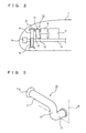
- This embodiment exemplifies a type of automobile or similar vehicle having a body 1 having a front portion provided with an engine room 2.
- engine room 2 accommodates an engine 3 as a matter of course, and a radiator 4, an intercooler 5, an air cleaner 6, a battery 7 and other similar equipment associated with engine 3.
- body 1 is assumed as including an engine hood and a bumper cover.
- a reference character 1a denotes a front bumper and reference characters 1b and 1c denote front side members.
- Radiator 4 is situated in engine room 2 under the radiator's upper support 8 arranged in body 1 at a front upper location.
- Intercooler 5 underlies the radiator's upper support 8 adjacent to radiator 4.
- Air cleaner 6 and battery 7 are situated in engine room 2 adjacent to one side of engine 3. Air cleaner 6 is situated inner than the radiator's upper support 8, separate therefrom and opposite thereto as seen in the fore-aft direction of body 1, and battery 7 is arranged behind air cleaner 6.
- Air cleaner 6 has an air inlet with an intake duct 10 attached thereto.
- Intake duct 10 introduces external air into air cleaner 6 and as shown in Fig. 2 it is located between the radiator's upper support 8 and air cleaner 6.
- intake duct 10 has a linear portion 11 extending along the radiator's upper support 8 or the body's width with one end serving as an inlet 11a introducing external air, an intermediate portion 12 located closer to the other end of linear portion 11 and extending downward, and a connection 13 extending from intermediate portion 12 rearward to connect to air cleaner 6.
- Intake duct 10 has linear portion 11 situated to overlap the radiator's upper support 8, as seen from a front side of body 1 in projective view.
- Intake duct 10 thus provided is entirely formed of an elastic material. More specifically, intake duct 10 is suitably formed of a material implemented by an elastic material including an elastomer formed of polypropylene (PP) and ethylene-propylene rubber (EPDM) mixed together.
- PP polypropylene
- EPDM ethylene-propylene rubber
- the elastomer serving as a material for intake duct 10 is excellent in that it is not only equivalent to rubber and the like in flexibility, oil resistance, heat resistance, tensile strength and tear strength, but also smaller in weight than rubber and the like and recyclable.
- Such intake duct 10 is formed of the above described elastomer by a generally well known blow molding technique. This technique is well known and will not be described herein.
- intake duct 10 is formed of elastomer and situated in engine room 2 at a front location between the radiator's upper support 8 and air cleaner 6 at a location intermediate as seen in the direction of the width of body 1 such that when intake duct 10 is seen from a front side of body 1 in projective view intake duct 10 overlaps the radiator's upper support 8.
- radiator's upper support 8 slightly bumps into an external object 20 and thus deforms toward engine room 2 by an amount, and together air cleaner 6 compresses intake duct 10 at linear portion 11 in the fore-aft direction of body 1, linear portion 11 does not fracture and is instead only elastically compressed and deformed.
- the present intake duct can reduce the possibility that it will fracture into pieces which in turn thrust into and thus damage radiator 4, intercooler 5 and the like, i.e., cause additional damage.
- the present intake duct can thus contribute to reduced damageability.
- intake duct 10 having linear portion 11 extending in the direction of the width of body 1 allows designing a structure ensuring that air is taken in efficiently and vibration and noise characteristics are ensured, i.e., it can be increased in length and diameter as soon as possible. Furthermore, intake duct 10 that does not overlie the radiator's upper support 8 allows body 1 to have a front portion designed to be reduced in height and hence designed with an increased degree of freedom.
- intake duct 10 is entirely formed of an elastic material. When intake duct 10 is attached to air cleaner 6 intake duct 10 can be elastically deformed and thus help an operation attaching the same.
Landscapes
- Engineering & Computer Science (AREA)
- Chemical & Material Sciences (AREA)
- Combustion & Propulsion (AREA)
- Transportation (AREA)
- Mechanical Engineering (AREA)
- Cooling, Air Intake And Gas Exhaust, And Fuel Tank Arrangements In Propulsion Units (AREA)
Applications Claiming Priority (1)
| Application Number | Priority Date | Filing Date | Title |
|---|---|---|---|
| JP2005041379A JP4412198B2 (ja) | 2005-02-17 | 2005-02-17 | 吸気ダクトの配置構造ならびに吸気ダクト |
Publications (3)
| Publication Number | Publication Date |
|---|---|
| EP1693239A2 true EP1693239A2 (de) | 2006-08-23 |
| EP1693239A3 EP1693239A3 (de) | 2007-10-31 |
| EP1693239B1 EP1693239B1 (de) | 2012-08-01 |
Family
ID=36407473
Family Applications (1)
| Application Number | Title | Priority Date | Filing Date |
|---|---|---|---|
| EP06003020A Expired - Lifetime EP1693239B1 (de) | 2005-02-17 | 2006-02-15 | Lufteinlasskanal für ein Fahrzeug |
Country Status (2)
| Country | Link |
|---|---|
| EP (1) | EP1693239B1 (de) |
| JP (1) | JP4412198B2 (de) |
Cited By (3)
| Publication number | Priority date | Publication date | Assignee | Title |
|---|---|---|---|---|
| FR2917339A1 (fr) * | 2007-06-13 | 2008-12-19 | Peugeot Citroen Automobiles Sa | Structure d'alimentation en air pour un moteur a combustion interne, moteur comportant une telle structure et vehicule equipe d'un tel moteur |
| FR2918609A1 (fr) * | 2007-07-11 | 2009-01-16 | Peugeot Citroen Automobiles Sa | Partie avant de vehicule comprenant un filtre a air en deux parties |
| US9027683B2 (en) | 2013-09-27 | 2015-05-12 | Toyota Motor Engineering & Manufacturing North America, Inc. | Elastically deformable air inlets and vehicles incorporating the same |
Families Citing this family (2)
| Publication number | Priority date | Publication date | Assignee | Title |
|---|---|---|---|---|
| JP2012197702A (ja) * | 2011-03-18 | 2012-10-18 | Toyota Motor Corp | 吸気マニホールド |
| JP6417860B2 (ja) * | 2014-11-04 | 2018-11-07 | スズキ株式会社 | 内燃機関の吸気装置 |
Citations (1)
| Publication number | Priority date | Publication date | Assignee | Title |
|---|---|---|---|---|
| EP0065183A1 (de) | 1981-05-11 | 1982-11-24 | Nissan Motor Co., Ltd. | Luftsaugschlauch für Fahrzeugmotor |
Family Cites Families (5)
| Publication number | Priority date | Publication date | Assignee | Title |
|---|---|---|---|---|
| JPH0214912A (ja) * | 1988-07-04 | 1990-01-18 | Nissan Motor Co Ltd | 車両用レゾネータの取付方法 |
| JP2526659Y2 (ja) * | 1991-06-24 | 1997-02-19 | マツダ株式会社 | 車両吸気ダクトの吸気取入構造 |
| JPH09189273A (ja) * | 1995-12-29 | 1997-07-22 | Isuzu Motors Ltd | 車両用エンジンの吸気装置 |
| JPH11303620A (ja) * | 1998-04-21 | 1999-11-02 | Inoac Corporation:Kk | 車両用ダクト |
| JP4045900B2 (ja) * | 2002-09-03 | 2008-02-13 | 日産自動車株式会社 | 車両用エンジンの吸気取入れ構造およびその製造方法 |
-
2005
- 2005-02-17 JP JP2005041379A patent/JP4412198B2/ja not_active Expired - Fee Related
-
2006
- 2006-02-15 EP EP06003020A patent/EP1693239B1/de not_active Expired - Lifetime
Patent Citations (1)
| Publication number | Priority date | Publication date | Assignee | Title |
|---|---|---|---|---|
| EP0065183A1 (de) | 1981-05-11 | 1982-11-24 | Nissan Motor Co., Ltd. | Luftsaugschlauch für Fahrzeugmotor |
Cited By (3)
| Publication number | Priority date | Publication date | Assignee | Title |
|---|---|---|---|---|
| FR2917339A1 (fr) * | 2007-06-13 | 2008-12-19 | Peugeot Citroen Automobiles Sa | Structure d'alimentation en air pour un moteur a combustion interne, moteur comportant une telle structure et vehicule equipe d'un tel moteur |
| FR2918609A1 (fr) * | 2007-07-11 | 2009-01-16 | Peugeot Citroen Automobiles Sa | Partie avant de vehicule comprenant un filtre a air en deux parties |
| US9027683B2 (en) | 2013-09-27 | 2015-05-12 | Toyota Motor Engineering & Manufacturing North America, Inc. | Elastically deformable air inlets and vehicles incorporating the same |
Also Published As
| Publication number | Publication date |
|---|---|
| JP2006226197A (ja) | 2006-08-31 |
| EP1693239B1 (de) | 2012-08-01 |
| JP4412198B2 (ja) | 2010-02-10 |
| EP1693239A3 (de) | 2007-10-31 |
Similar Documents
| Publication | Publication Date | Title |
|---|---|---|
| CN103161622B (zh) | 安装在发动机舱中的车辆发动机的进气系统 | |
| US7523798B2 (en) | Support structure of cooling air intake duct for intercooler of vehicle | |
| US8464546B2 (en) | Pipe structure of electric compressor | |
| US6880655B2 (en) | Air-intake structure around front grille for vehicle | |
| US7998232B2 (en) | Housing which can be secured to a motor vehicle with an integrated pedestrain protection function | |
| US9643483B2 (en) | Air duct for vehicle | |
| US7318469B2 (en) | Piping structure for refrigerant cycle system of vehicle | |
| US8807113B2 (en) | Device and method for integrating an air cleaner into a radiator fan shroud | |
| EP1693239B1 (de) | Lufteinlasskanal für ein Fahrzeug | |
| US20090152902A1 (en) | Front structure of vehicle | |
| US7287518B2 (en) | Vehicle fuel supply construction | |
| US20090031980A1 (en) | Air cleaner intake duct | |
| JP4623421B2 (ja) | 車体前部構造 | |
| JP4046002B2 (ja) | エンジンの燃料系統保護装置 | |
| US11293344B2 (en) | Cover member mounting structure for engine | |
| CN102787954A (zh) | 车辆用涡轮增压器的配管结构 | |
| JP2003035228A (ja) | エンジンの吸気装置 | |
| JP7786259B2 (ja) | 多気筒エンジンの側部構造 | |
| JP4716511B2 (ja) | エンジン部品の取付け装置 | |
| KR102027057B1 (ko) | 사이드 임팩트에 대응하기 위한 사이드 아우터 패널 어셈블리 | |
| EP1849642B1 (de) | Anordnungsstruktur für einen Lufteinlasskasten | |
| JP4707613B2 (ja) | 車両用内燃機関における吸気装置 | |
| JP2007192160A (ja) | 車両の衝撃吸収構造 | |
| JP2007191029A (ja) | 車両の前部構造 | |
| WO2023058514A1 (ja) | 自動車用エンジンのカバー |
Legal Events
| Date | Code | Title | Description |
|---|---|---|---|
| PUAI | Public reference made under article 153(3) epc to a published international application that has entered the european phase |
Free format text: ORIGINAL CODE: 0009012 |
|
| 17P | Request for examination filed |
Effective date: 20060215 |
|
| AK | Designated contracting states |
Kind code of ref document: A2 Designated state(s): AT BE BG CH CY CZ DE DK EE ES FI FR GB GR HU IE IS IT LI LT LU LV MC NL PL PT RO SE SI SK TR |
|
| AX | Request for extension of the european patent |
Extension state: AL BA HR MK YU |
|
| PUAL | Search report despatched |
Free format text: ORIGINAL CODE: 0009013 |
|
| AK | Designated contracting states |
Kind code of ref document: A3 Designated state(s): AT BE BG CH CY CZ DE DK EE ES FI FR GB GR HU IE IS IT LI LT LU LV MC NL PL PT RO SE SI SK TR |
|
| AX | Request for extension of the european patent |
Extension state: AL BA HR MK YU |
|
| AKX | Designation fees paid |
Designated state(s): DE FR GB IT |
|
| 17Q | First examination report despatched |
Effective date: 20090216 |
|
| 17Q | First examination report despatched |
Effective date: 20100415 |
|
| 17Q | First examination report despatched |
Effective date: 20110302 |
|
| GRAP | Despatch of communication of intention to grant a patent |
Free format text: ORIGINAL CODE: EPIDOSNIGR1 |
|
| GRAS | Grant fee paid |
Free format text: ORIGINAL CODE: EPIDOSNIGR3 |
|
| GRAA | (expected) grant |
Free format text: ORIGINAL CODE: 0009210 |
|
| RIN1 | Information on inventor provided before grant (corrected) |
Inventor name: GOTO, ISAO Inventor name: YOSHIMURA, HITOSHI |
|
| AK | Designated contracting states |
Kind code of ref document: B1 Designated state(s): DE FR GB IT |
|
| REG | Reference to a national code |
Ref country code: GB Ref legal event code: FG4D |
|
| REG | Reference to a national code |
Ref country code: DE Ref legal event code: R096 Ref document number: 602006031025 Country of ref document: DE Effective date: 20120927 |
|
| RAP2 | Party data changed (patent owner data changed or rights of a patent transferred) |
Owner name: TOYOTA JIDOSHA KABUSHIKI KAISHA |
|
| PLBE | No opposition filed within time limit |
Free format text: ORIGINAL CODE: 0009261 |
|
| STAA | Information on the status of an ep patent application or granted ep patent |
Free format text: STATUS: NO OPPOSITION FILED WITHIN TIME LIMIT |
|
| 26N | No opposition filed |
Effective date: 20130503 |
|
| REG | Reference to a national code |
Ref country code: DE Ref legal event code: R097 Ref document number: 602006031025 Country of ref document: DE Effective date: 20130503 |
|
| REG | Reference to a national code |
Ref country code: GB Ref legal event code: 746 Effective date: 20130923 |
|
| REG | Reference to a national code |
Ref country code: DE Ref legal event code: R084 Ref document number: 602006031025 Country of ref document: DE Effective date: 20130919 |
|
| REG | Reference to a national code |
Ref country code: FR Ref legal event code: PLFP Year of fee payment: 11 |
|
| REG | Reference to a national code |
Ref country code: FR Ref legal event code: PLFP Year of fee payment: 12 |
|
| PGFP | Annual fee paid to national office [announced via postgrant information from national office to epo] |
Ref country code: FR Payment date: 20170112 Year of fee payment: 12 Ref country code: DE Payment date: 20170207 Year of fee payment: 12 |
|
| PGFP | Annual fee paid to national office [announced via postgrant information from national office to epo] |
Ref country code: GB Payment date: 20170215 Year of fee payment: 12 |
|
| PGFP | Annual fee paid to national office [announced via postgrant information from national office to epo] |
Ref country code: IT Payment date: 20170221 Year of fee payment: 12 |
|
| REG | Reference to a national code |
Ref country code: DE Ref legal event code: R119 Ref document number: 602006031025 Country of ref document: DE |
|
| GBPC | Gb: european patent ceased through non-payment of renewal fee |
Effective date: 20180215 |
|
| REG | Reference to a national code |
Ref country code: FR Ref legal event code: ST Effective date: 20181031 |
|
| PG25 | Lapsed in a contracting state [announced via postgrant information from national office to epo] |
Ref country code: DE Free format text: LAPSE BECAUSE OF NON-PAYMENT OF DUE FEES Effective date: 20180901 |
|
| PG25 | Lapsed in a contracting state [announced via postgrant information from national office to epo] |
Ref country code: FR Free format text: LAPSE BECAUSE OF NON-PAYMENT OF DUE FEES Effective date: 20180228 Ref country code: GB Free format text: LAPSE BECAUSE OF NON-PAYMENT OF DUE FEES Effective date: 20180215 Ref country code: IT Free format text: LAPSE BECAUSE OF NON-PAYMENT OF DUE FEES Effective date: 20180215 |