EP1691209A1 - Procédé et appareil de détection de l'état de charge d'une batterie de secours, basés sur un calcul de réseau neuronal - Google Patents
Procédé et appareil de détection de l'état de charge d'une batterie de secours, basés sur un calcul de réseau neuronal Download PDFInfo
- Publication number
- EP1691209A1 EP1691209A1 EP06002917A EP06002917A EP1691209A1 EP 1691209 A1 EP1691209 A1 EP 1691209A1 EP 06002917 A EP06002917 A EP 06002917A EP 06002917 A EP06002917 A EP 06002917A EP 1691209 A1 EP1691209 A1 EP 1691209A1
- Authority
- EP
- European Patent Office
- Prior art keywords
- battery
- voltage
- state
- open
- circuit voltage
- Prior art date
- Legal status (The legal status is an assumption and is not a legal conclusion. Google has not performed a legal analysis and makes no representation as to the accuracy of the status listed.)
- Granted
Links
- 238000013528 artificial neural network Methods 0.000 title claims abstract description 191
- 238000004364 calculation method Methods 0.000 title claims abstract description 128
- 238000000034 method Methods 0.000 title claims description 41
- 230000004044 response Effects 0.000 claims description 55
- 230000015654 memory Effects 0.000 claims description 52
- 230000014509 gene expression Effects 0.000 claims description 49
- 230000006870 function Effects 0.000 claims description 48
- 230000015556 catabolic process Effects 0.000 claims description 39
- 230000008878 coupling Effects 0.000 claims description 39
- 238000010168 coupling process Methods 0.000 claims description 39
- 238000005859 coupling reaction Methods 0.000 claims description 39
- 238000006731 degradation reaction Methods 0.000 claims description 39
- 238000012545 processing Methods 0.000 claims description 33
- 230000007935 neutral effect Effects 0.000 claims description 15
- 230000036541 health Effects 0.000 claims description 9
- 238000012886 linear function Methods 0.000 claims description 5
- 238000012360 testing method Methods 0.000 description 93
- 238000001514 detection method Methods 0.000 description 54
- 238000012986 modification Methods 0.000 description 48
- 230000004048 modification Effects 0.000 description 48
- 230000000875 corresponding effect Effects 0.000 description 19
- 238000010586 diagram Methods 0.000 description 17
- 238000007599 discharging Methods 0.000 description 17
- 230000000052 comparative effect Effects 0.000 description 16
- 230000008569 process Effects 0.000 description 13
- 238000005314 correlation function Methods 0.000 description 9
- 238000005070 sampling Methods 0.000 description 9
- 238000012937 correction Methods 0.000 description 8
- 238000005259 measurement Methods 0.000 description 6
- 230000010354 integration Effects 0.000 description 5
- 230000010287 polarization Effects 0.000 description 5
- 230000008901 benefit Effects 0.000 description 3
- 230000000694 effects Effects 0.000 description 3
- 230000006872 improvement Effects 0.000 description 2
- 238000004519 manufacturing process Methods 0.000 description 2
- 230000002123 temporal effect Effects 0.000 description 2
- 238000013459 approach Methods 0.000 description 1
- 230000037396 body weight Effects 0.000 description 1
- 238000010276 construction Methods 0.000 description 1
- 230000010485 coping Effects 0.000 description 1
- 230000002596 correlated effect Effects 0.000 description 1
- 230000003247 decreasing effect Effects 0.000 description 1
- 238000011156 evaluation Methods 0.000 description 1
- 238000002474 experimental method Methods 0.000 description 1
- 230000002349 favourable effect Effects 0.000 description 1
- 238000001914 filtration Methods 0.000 description 1
- 238000007781 pre-processing Methods 0.000 description 1
- 230000009467 reduction Effects 0.000 description 1
- 238000012546 transfer Methods 0.000 description 1
Images
Classifications
-
- F—MECHANICAL ENGINEERING; LIGHTING; HEATING; WEAPONS; BLASTING
- F25—REFRIGERATION OR COOLING; COMBINED HEATING AND REFRIGERATION SYSTEMS; HEAT PUMP SYSTEMS; MANUFACTURE OR STORAGE OF ICE; LIQUEFACTION SOLIDIFICATION OF GASES
- F25D—REFRIGERATORS; COLD ROOMS; ICE-BOXES; COOLING OR FREEZING APPARATUS NOT OTHERWISE PROVIDED FOR
- F25D16/00—Devices using a combination of a cooling mode associated with refrigerating machinery with a cooling mode not associated with refrigerating machinery
-
- G—PHYSICS
- G01—MEASURING; TESTING
- G01R—MEASURING ELECTRIC VARIABLES; MEASURING MAGNETIC VARIABLES
- G01R31/00—Arrangements for testing electric properties; Arrangements for locating electric faults; Arrangements for electrical testing characterised by what is being tested not provided for elsewhere
- G01R31/36—Arrangements for testing, measuring or monitoring the electrical condition of accumulators or electric batteries, e.g. capacity or state of charge [SoC]
- G01R31/3644—Constructional arrangements
- G01R31/3648—Constructional arrangements comprising digital calculation means, e.g. for performing an algorithm
-
- F—MECHANICAL ENGINEERING; LIGHTING; HEATING; WEAPONS; BLASTING
- F25—REFRIGERATION OR COOLING; COMBINED HEATING AND REFRIGERATION SYSTEMS; HEAT PUMP SYSTEMS; MANUFACTURE OR STORAGE OF ICE; LIQUEFACTION SOLIDIFICATION OF GASES
- F25D—REFRIGERATORS; COLD ROOMS; ICE-BOXES; COOLING OR FREEZING APPARATUS NOT OTHERWISE PROVIDED FOR
- F25D23/00—General constructional features
- F25D23/06—Walls
- F25D23/065—Details
- F25D23/068—Arrangements for circulating fluids through the insulating material
-
- G—PHYSICS
- G01—MEASURING; TESTING
- G01R—MEASURING ELECTRIC VARIABLES; MEASURING MAGNETIC VARIABLES
- G01R31/00—Arrangements for testing electric properties; Arrangements for locating electric faults; Arrangements for electrical testing characterised by what is being tested not provided for elsewhere
- G01R31/36—Arrangements for testing, measuring or monitoring the electrical condition of accumulators or electric batteries, e.g. capacity or state of charge [SoC]
- G01R31/367—Software therefor, e.g. for battery testing using modelling or look-up tables
-
- G—PHYSICS
- G01—MEASURING; TESTING
- G01R—MEASURING ELECTRIC VARIABLES; MEASURING MAGNETIC VARIABLES
- G01R31/00—Arrangements for testing electric properties; Arrangements for locating electric faults; Arrangements for electrical testing characterised by what is being tested not provided for elsewhere
- G01R31/36—Arrangements for testing, measuring or monitoring the electrical condition of accumulators or electric batteries, e.g. capacity or state of charge [SoC]
- G01R31/382—Arrangements for monitoring battery or accumulator variables, e.g. SoC
- G01R31/3842—Arrangements for monitoring battery or accumulator variables, e.g. SoC combining voltage and current measurements
-
- F—MECHANICAL ENGINEERING; LIGHTING; HEATING; WEAPONS; BLASTING
- F25—REFRIGERATION OR COOLING; COMBINED HEATING AND REFRIGERATION SYSTEMS; HEAT PUMP SYSTEMS; MANUFACTURE OR STORAGE OF ICE; LIQUEFACTION SOLIDIFICATION OF GASES
- F25D—REFRIGERATORS; COLD ROOMS; ICE-BOXES; COOLING OR FREEZING APPARATUS NOT OTHERWISE PROVIDED FOR
- F25D2201/00—Insulation
- F25D2201/10—Insulation with respect to heat
- F25D2201/12—Insulation with respect to heat using an insulating packing material
Definitions
- the present application relates to and incorporates by reference Japanese Patent application Nos. 2005-036442 filed on Feb. 14, 2005, 2005-036437 filed on Feb. 14, 2005, 2005-039614 filed on Feb. 16, 2005, 2005-122011 filed on Apr. 20, 2005, 2005-122004 filed on Apr. 20, 2005, and 2005-151050 filed on May 24, 2005.
- the present invention relates to a battery system with a neural network type of apparatus for detecting a charged state of a secondary (rechargeable) battery, and in particular, to an improvement in detection of the charged state of such a battery which is for example mounted on vehicles.
- An on-vehicle battery system is mostly composed of a secondary battery such as lead batteries.
- degrees of degradation give fluctuations to correlations between electric quantities of a battery, such as voltage and current, and charged state quantities of the battery, such as an SOC (state of charge) and an SOH (state of health).
- the SOC indicates a charged rate [%] of a battery and the SOH indicates a residual capacity [Ah] of a battery.
- the precision in detecting the SOC and/or SOH will be degraded, whereby the SOC and/or SOH will fluctuate battery by battery.
- Some known references which are for instance Japanese Patent Laid-open Publications Nos. 9-243716 and 2003-249271, propose a technique to improve the above situation. That is, those references propose how to detect the SOC and/or SOH of a secondary battery with the use of neural network (, which is called "neural network type of detection of battery state").
- the publication No. 9-243716 provides a technique of detecting the residual capacity of a battery, in which input parameters including at least an open-circuit voltage, a voltage detected immediately after a discharge, and an internal resistance are used for allowing a leaned neutral network to calculate the residual capacity.
- the publication No. 2003-249271 also provides a technique of detecting the residual capacity of a battery, In which data of voltage, current and internal resistance of a battery and a temperature are inputted to a first learned neural network to calculate information showing degradations of the battery, and this information and the data of voltage, current and internal resistance of the battery are Inputted to a second learned neural network to calculate the residual capacity of the battery.
- the neural network Since the neural network has fiexibility in coping with fluctuations in the characteristic of an object to be measured, the neural network has been used for the detection of battery state, explained above.
- a present value of an open-circuit voltage and an internal resistance of a battery which can be estimated using a least-squares method, are added to input parameters.
- data of those present values and voltage and current history are given to a neural network as the input parameters.
- Those additional data that is, the present values reflecting the operating state of a battery, enable the detection of an output parameter such as SOC and SOH to be enhanced in precision, with less influenced by degradations of the battery.
- the present invention has been completed with the above view in mind and has an object to provide a method and apparatus for detecting charged state of a secondary battery based on neural network calculation, which is able to provide an output parameter with a higher precision, regardless of differences in charge and discharge characteristics of individual batteries, the differences resulting from, for example, degrees of temporal degradations (cycle degradations) and/or differences in battery types.
- Another object of the present Invention is, solely or in combination with the above object, to provide an apparatus for detecting charged state of a secondary battery based on neural network calculation, which is able to provide an output parameter with less input parameters, while still maintaining a higher precision in detecting information showing charged states of the battery.
- a neural network type of apparatus for detecting an internal state of a secondary battery (rechargeable) implemented in a battery system comprising: detecting means for detecting electric signals indicating an operating state of the battery; producing means for producing, using the electric signals, an input parameter required for estimating the internal state of the battery, the input parameter reflecting calibration of a present charged state of the battery; and estimating means for estimating an output parameter indicating the charged state of the battery by applying the Input parameter to neural network calculation.
- the electric signals are voltage and current of the battery acquired in real time during a predetermined period of time; the input parameter consisting of a first input parameter indicating the operating state of the battery and a second Input parameter indicating the degraded state of the battery; and the producing means comprises means for calculating the first input parameter on the basis of data of the voltage and current of the battery, and means for calculating the second input parameter in response to a state of predetermined charge of the battery (for example, to a state in which a predetermined amount of power from the battery which has been fully charged is discharged).
- a state of predetermined charge of the battery for example, to a state in which a predetermined amount of power from the battery which has been fully charged is discharged.
- the outputting parameter estimating means is means for calculating the output parameter indicating a present charged state of the battery by processing both the first and second input parameters based on a neural network calculation technique.
- the battery is no longer new, but becomes a used (i.e., degraded in the performance) battery, in which the degree of degradation (cycle degradation) of the battery changes while it is used.
- the degree of degradation of each battery depends on the battery type. That is, the present charged states of all used batteries are different battery by battery. Therefore, such different charged states are all reflected in the "present charged state" stated above.
- the foregoing fundamental configuration adopts the technique of including, into the input parameters for neural network calibration, data of calibration of a present charged state of a battery, the calibration reflecting, as described, for example, the degree of degradation in charge/discharge of a used battery.
- Including such calibration data into the input parameters enables an output parameter to be calculated (estimated) more accurately than, for example, a situation where data of voltage and current history are simply used as input parameters.
- the charged state of a used battery can be checked with high precision, with automatically tracking temporal degradations of the charge/discharge performance of the used battery.
- a charge-related physical quantity showing a correlation with changes in an output parameter (such as an SOC) due to, for example, degradations of a used battery.
- an output parameter such as an SOC
- a charge-related physical quantity is an open-circuit voltage to be detected in response to a state of predetermined charge of a battery.
- This kind of charge-related physical quantity is referred to as a second input parameter in one aspect of the present embodiment, in which the second input parameter is combined with a first input parameter to form the input parameter fed to a neural network calculator that is in charge of performing the neural network calculation.
- the charge-related physical quantities which can be adopted in the present invention, include a difference between open-circuit voltages obtained responsively to a full charge of a battery and to discharging a predetermined amount of power from a full charge power of the battery.
- a quantity also useful is a combination of the above voltage difference and an open-circuit voltage obtained responding to a discharge of a predetermined amount of power from a battery in a full charge.
- an internal resistance of a battery obtained in response to discharging a predetermined amount of power from a battery in a full charge may be used as such a charge-related physical quantity.
- Such various quantities have correlations with changes in the SOC and SOH of a battery, so that they can be used as calibration data for correction of changes in the charge/discharge characteristics of each battery that is attributable to degradations and/or differences of battery types.
- the first input parameter calculating means is configured to calculate, as the first input parameter, voltage history data and current history data based on data of the received voltage and current of the battery;
- the second Input parameter calculating means is configured to calculate, as the second Input parameter, an open-circuit voltage of the battery and an Internal resistance of the battery using both the voltage history data and the current history data In response to a state of predetermined charge of the battery;
- the outputting parameter estimating means is means for calculating the output parameter Indicating a full charge capacity of the battery, the full charge capacity being expected at present.
- the precision for the neural network calculation can be done with high precision, while still preventing the input parameter from being increased. Accordingly, the size of a neural network calculator can be kept smaller, but the full charge capacity of a used battery can be calculated with precision, even compared to conventional calculators with or without a neural network. And the time for calculation can be kept in a period of time required for practical use. As a result, with no paying attention to over-charge and over-discharge, the capacity range for use can be widened.
- a battery can be made more compact, while still being enough for covering a necessary discharge capacity range for the battery. This will lead to not merely less space occupation for mounting a battery on vehicles but also a decrease In the vehicle body weight. In consequence, the second object of the present invention can also be attained.
- the electric signals are voltage and current of the battery acquired in real time during a predetermined period of time;
- the estimating means comprises a neural network having the input layer which receives the input parameter and an intermediate layer which performs neural network calculation using both of the input parameters and rewritable coupling coefficients mutually connecting the Input layer, the Intermediate layer, and an output layer so as to estimate the output parameter and allow the output parameter to be outputted from the output layer, the output parameter indicating the charged state of the battery;
- the producing means comprises a memory with a plurality of memory tables each storing the coupling coefficients, the coupling coefficient stored in the memory tables being different from one another table by table and depending on divided ranges of a characteristic of a specified input parameter specified in the input parameter, the specified input parameter having a correlation with a degraded state of the battery; and selecting means for selecting, in response to a present value of the specified input parameter, a memory table from the plurality of memory tables to read in the coupling coefficients stored therein, the specified coupling
- the input parameters include voltage history data, current history data, and an open-circuit voltage of the battery which are estimated on the voltage and current of the battery and the specified input parameter is an open-circuit voltage of the battery to be obtained when the battery is In a fully charged state thereof.
- the producing means is configured to produce the Input parameter which is calibrated depending on a charge and discharge characteristic of the battery which is attributable to at least one of the degraded state of the battery and the difference in types of the battery.
- the input parameter includes either a voltage V of the battery or a ratio V/Vf wherein Vf is a voltage of the battery detected when the battery is in a fully charged state, either an open-circuit voltage Vo of the battery or a ratio of Vo/Vof wherein Vof is an open-circuit voltage detected when the battery is in a fully charged state, either an Internal resistance R of the battery or a ratio of R/Rf wherein Rf is an internal resistance detected when the battery is in a fully charged state, a predetermined function f(Vo, R) using, as input variables, the open-circuit voltage Vo and the internal resistance R and expressing a correlation to an amount of current of the battery which is dischargeable at present, and a current I of the battery.
- the input parameters include the function value f (Vo, R) whose variables Vo and R are individually correlated with a degradation and a residual capacity of each battery, respectively.
- the function value f (Vo, R) which shows a dischargeable amount of power, has higher correlations with degraded states and charged states of each battery.
- the input parameter is composed of a plurality of physical state quantities reflecting the present charged state of the battery and the plurality of physical state quantities include a ratio between a present value of a physical state quantity specified among the physical state quantifies and a value of the specified physical state quantity acquired in response to a state of predetermined charge of the battery (for example, in response to discharging a predetermined amount of power from the battery which has fully been charged).
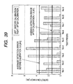
- the following embodiments are made up of eight embodiments, which are: a first embodiment (including modifications) described in connection with Figs. 1 - 9 and 94; a second embodiment (including modifications) described in connection with Figs. 10 - 14; a third embodiment (including modifications) described in connection with Figs. 15 - 24; a fourth embodiment (including modifications) described in connection with Figs. 25 - 35; a fifth embodiment (including modifications) described in connection with Figs. 36 - 39; a sixth embodiment (including modifications) described in connection with Figs. 40 - 49; a seventh embodiment (including modifications) described in connection with Figs. 50 - 68; and an eighth embodiment (including modifications) described in connection with Figs. 69 - 93.
- SOH state of health
- SOC state of charge
- Q full charge capacity
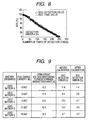
- an SOH of 25.6 Ah corresponds to an SOC of 40 %.
- this capacity amount still corresponds to an SOC of 100 % and, in this case, an SOC of 40 % means an SOH of 16.0 Ah.
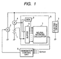
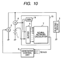
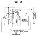
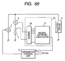
- This on-vehicle battery system is based on neural network type of calculation and corresponds to a battery system according to the present invention.
- the on-vehicle battery system is provided with an on-vehicle battery (hereinafter, simply referred to as a "battery") 1 and other electric components including an on-vehicle generator 2, an electric device(s) 3, a current sensor 4, a battery state detector 5, and a generator control unit 6.
- the battery state detector 5 is equipped with a neural network calculator 7, a buffer 8, and a correcting signal generator 9 and may be, in part or as a whole, formed by either a computer configuration or a structure on digital/analog circuitry.
- the on-vehicle generator 2 is mounted on the vehicle to charge the battery 1 and power the electric device 3.
- the electric device 3 functions as an on-vehicle electric load(s) which is powered by the battery 1 or the generator 2.
- the current sensor 4 Is placed between the battery 1 and the electric device 2 to detect charge and discharge currents to and from the battery 1.
- the battery state detector 5 is an electric circuit unit to detect signals indicating the internal operation (charge/discharge) states of the battery 1.
- a terminal of the battery 1 is connected to the battery state detector 5 such that its terminal voltage (simply, voltage) is provided to the battery state detector 5.
- the buffer 8 mainly has two functions; one is to receive data of both voltage (terminal voltage) V and current I of the buttery for memorization and output those data as data showing voltage history Vi and current history Ii and the other is to calculate and output a present value of an open-circuit voltage Vo and/or a present value of an internal resistance R of the battery 1.
- the open-circuit voltage Vo is a voltage which appears on the battery terminals provided that a load current therefrom is regarded as being zero.
- the neural network calculator 7 is configured to receive various types of signals to be inputted from both the buffer 8 and the correcting signal generator 9 and applies neural network calculation to the inputted signals so as to output signals indicative of a predetermined storage state quantity (an SOC (state of charge) in the present embodiment). Further, the correcting signal generator 9 is configured to calculate calibration data, as will be described later, to output the calculate calibration data as part of the input data to the neural network calculator 7.
- a predetermined storage state quantity an SOC (state of charge) in the present embodiment
- the generator control unit 6 is placed to control an amount of power to be generated by the on-vehicle generator 2 in response to both of a signal outputted from the neural network calculator 7 and signals S other coming from various other not-shown components.
- the circuitry is characteristic in that the battery state detector 5 is equipped with the correcting signal generator 9 as well as both the buffer 8 and the neural network generator 7.
- the buffer 8, neural network calculator 7 and correcting signal generator 9, that is, the battery state detector 5, are, for example in the present embodiment, made up of a microcomputer system that operates on software previously installed therein. But this is not always a definitive list. A dedicated software circuit can replace the battery state detector 5.
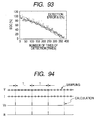
- the buffer 8 which functions as a pre-signal processing circuit for the neural network calculator 7, samples, simultaneously and at intervals (for example, T/5 seconds and T is 25 seconds; refer to Fig. 94), both a signal of the voltage V of the battery 1 and a signal of current I from the current sensor 4 for memorizing data indicative of the battery voltage history Vi and buttery current history II, and supplies, in parallel, data indicative of voltage V and current I at each time instant to the neural network calculator 7.
- a predetermined period of time e.g. 25 seconds, refer to Fig. 94
- the voltage history data Vi and current history data Il are sampled at intervals to produce five data, respectively (refer to Fig. 94), but this is not a definitive list.
- the buffer 6 creates data that shows a relationship between the buttery voltage history Vi and the buttery current history Il and provides the neural network calculator 7 with such relationship data.
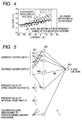
- Such relationship data are created such that the data of both the voltage history Vi and current history Il are subjected to the least-squares method to compute a linear approximate expression LN showing the relationship between the voltage and current V and I, and the approximate expression LN is subjected to calculation of a y-intercept (corresponding to an open-circuit voltage Vo) and/or slope (corresponding to an internal resistance R) every time when pairs of voltage V and current I are inputted, whereby a present value of the open-circuit voltage Vo and/or a present value of the internal resistance R are created (refer to Fig.
- the foregoing least-squares method is helpful in reducing an amount of data to be memorized.
- the present value of the open-circuit voltage Vo is more significant than that of the internal resistance R.
- the present value of the internal resistance R may be omitted from the calculation. It may also be possible to omit, from the calculation, if necessary, the present values of the open-circuit voltage Vo and/or the internal resistance R.
- This generator 9 is formed as a computer system that has a CPU (central processing unit) and memories, though not shown.
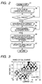
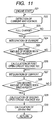
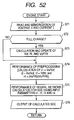
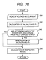
- the CPU operates on software described by a flowchart composed of various processing steps, which is shown in Fig. 2 and previously memorized in a memory.
- the CPU i.e., the correcting signal generator 9 calculates an open-circuit voltage Vo detected when the battery 1 discharges power from its full charge state by a predetermined amount of power (i.e., discharge of a predetermined amount of power).
- the generator 9 provides the neural network calculator 7 with the resultant open-circuit voltage Vo serving as calibration data to be used for its neural network calculation.
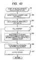
- the correcting signal generator 9 starts its calculation (step S1). After the start, the generator 9 detects the voltage V and the current I of the battery 1 at intervals (step S2), and then uses the detected voltage V and current I so that the detected values are subjected to a determination whether the battery 1 is in its full charge state (i.e., a full charge determination) which will be described later (step S3). The generator 9 then determines whether or not an integrated current value (Ah) reaches a predetermined threshold which is equivalent to a predetermined discharge amount (steps S4 and S5). In the present embodiment, the predetermined threshold is set to a value of 100 to 95 % of the initial SOC. The voltage V and current I can be subjected to noise reduction such as low-pass filtering to pickup a DC component.
- a value of the open-circuit voltage Vo which Is obtained when such a determination is made, Is set to an open-circuit voltage value Vo to be used when a determined amount of power is discharged (step S6).
- the open-circuit value Vo shows a degraded state quantity obtained when the determined amount of power is discharged, which corresponds to the present invention.
- the open-circuit voltage Vo is updated to the calculated value (step S7). This open-circuit voltage Vo is calculated in the same way as the present value of the foregoing open-circuit voltage.
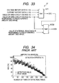
- Fig. 3 shows a two-dimensional map on which pairs of data of voltage V and current I of the battery 1, which are sampled at intervals and memorized in the buffer 8, are mapped two-dimensionally.
- a predetermined area is predetermined for use in determining the fully charged state.
- a coordinate point specified a pair of voltage V and current I detected at present is made reference to the map as to whether the point resides in the predetermined area in the map shown in Fig. 3. If the point is within the predetermined area, it is determined that the battery 1 is in its fully charged state.
- the voltage V meeting such a condition is defined as an open-circuit voltage Vo full in response to the fully charged state.
- the voltage V and the current I may be replaced by an average voltage Va and an average current Ia which are mean values over a predetermined short period of time immediacy before the present sampling.
- the least-squares method is first applied to data of plural pairs of voltage and current V and I which are inputted during a specified period of time counted immediately before the power is discharged from its full state by a predetermined amount, so that the linear approximate expression LN defining a relationship between the voltage V and current I is obtained.
- the number of voltage/current pairs is set to a predetermined value, Then the open-circuit voltage Vo is calculated as a y-intercept value of the approximate expression LN. This calculated value is treated as the foregoing open-circuit voltage obtained when a predetermined amount of power is discharged.
- polarization factor may be used to select the voltage and current data V and I. That is, data indicative of past currents can be used to obtain polarization factors showing polarized states of a battery. Thus, only the voltage and current values whose polarization factors are within a predetermined range are selectively used for creating the linear approximate expression LN.
- the neural network calculator 7 will now be detailed in terms of its functional configuration and its operations.
- the neural network calculator 7 is formed into a three hierarchical feed-forward type of calculator which learns on a back-propagation technique. This type Is not decisive, but any neural network type, If selected properly, can be applied to this calculator 7.
- the neural network calculator 7 is composed of, as its functional blocks, an input layer 201, an Intermediate layer 202, and an output layer 203. Practically, however, this calculator 7 is configured to have a microcomputer system including a CPU and memories and the CPU executes programs read out from a memory, software processing, at intervals given for its calculation.
- the input layer 201 is composed of a predetermined number of input sells.
- the respective input cells not only receive, as input data (signals), voltage history data Vi, current history data Ii, and present values of the open-circuit voltage Vo and internal resistance R from the buffer 8 but also receive a value of the open-circuit voltage Vo obtained when the predetermined amount of power is discharged, from the correcting signal generator 9.
- the respective Input cells hand the received data to all calculation cells belonging to the intermediate layer 202.
- the calculation cells in the intermediate layer 202 are in charge of applying later-descried neural network calculation to the data to be inputted from the input cells in the input layer 201 and providing resultant calculation results to an output cell in the output layer 203. Since the calculation is directed to an SOC, so that the output cell in the output layer 203 produces as an output data showing the state of charge (SOC).
- the expression (2) is defined by using f (INPUTk(t) + b) which is a non-linear function called sigmoid function which uses INPUTk(t) + b as an Input variable.
- Wk a coupling coefficient between the k-th cell of the intermediate layer 202 and a cell of the output layer 203
- the neural network calculation according to the present embodiment introduces a learning process in which the coupling coefficients of between the cells are optimized so as to minimize errors between a final output OUT(t) at a time t and a previously measured target output (that is, a true value tar(t)) which will described later.
- the output OUT(t) is an output parameter to be outputted from the output layer 203 and, In the present embodiment, an SOC (state of charge) at a time t.
- a target to be outputted from the neural network calculator 7 is a quantity indicating the state of the battery 1 (i.e., charged state quantity).
- the charged state quantity is an SOC (state of charge).
- the neural network calculator 7 gives properly selected Initial values to the coupling coefficients (step S11).
- the initial values are decided by using a random table, for example.
- the calculator 7 reads in, as input signals, the foregoing input signals for learning and receives at each cell of the input layer 201 (step S12).
- the input signals are subjected to the neural network calculation so that a value of the SOC, i.e., the output parameter, is figured out (step S13).
- the calculator 7 calculates the error function Ek according to the foregoing expression (step S14) and determines whether or not the error function Ek represents a value smaller than a threshold "th" serving as a given minute value (step S15). In cases where the value of the error function Ek Is equal to or more than the threshold th, the calculator 7 allows the coupling coefficients Wk and Wjk to be subjected to the update so as to figure out update amounts ⁇ W, which are defined as above In the learning process (step S16), and then proceeds to the update of the coupling coefficients Wk and Wjk (step S17).
- step S12 The processing in the neural network calculator 7 is then returned to step S12 to read again the input signals for learning at the cells of the input layer 201.
- the SOC is calculated again as the above and repeat the foregoing processing until the error function Ek has a value smaller than the threshold th.
- the calculator 7 determines that the error function Ek presents a value smaller than the threshold th, the calculator 7 decides that the learning has been completed (step S18). In response to this decision, the learning process is ended.
- the neural network calculator 7 can be manufactured such that the calculator 7 previously learns several charge/discharge patterns corresponding to representative battery types based on the foregoing learning process or learning results are previously written into this calculator 7 before shipment of the products. This makes it possible to sequentially estimate the SOC of an on-vehicle battery which is mounted on a commercially available vehicle.
- the last value detected as the open-circuit voltage Vo may be held. This way also provides another approach to updating the open-circuit voltage Vo concerning the full charge, whereby the SOC can precisely be detected depending on how much the battery 1 is degraded during use thereof.
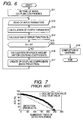
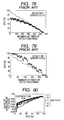
- a neural network calculator which has learned some charge/discharge patterns (10.15 mode) of some batteries including performance-degraded batteries was prepared. Another charge/discharge pattern (10.15 mode) for a further performance-degraded (i.e., used) battery was inputted to the calculator, with the neural network calculation performed on the pattern so that a SOC (i.e., charged rate) was obtained. The results are shown in Fig. 7.
- the input signals to the neural network calculator 7 were signals showing voltage history data VI and current history data Ii, a present value of the open-circuit voltage Vo, and a present value of the internal resistance R.
- Data of the open-circuit voltage Vo acquired when a predetermined amount of power is discharged was not used In this test.
- This used battery has an open-circuit voltage Vo of 12.9 V in the full charge state, which is higher than an open-circuit voltage Vo of 12.4 V in the full charge state of a band-new battery.
- an error of the SOC detection was as large as 20.7 % (as a mean square error).
- a state of a predetermined charge of a battery corresponds, by way of example, to a state in which a predetermined amount of power is discharged from the battery 1 which has fully been charged.
- the Input signals may be limited to only data of the voltage history Vi and the current history Il and data of the open-circuit voltage Vo gained when a predetermined amount of power is discharged may be used as calibration data.
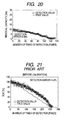
- comparative tests were conducted on SOC detection errors of further used batteries using two configurations; one was conducted with the use of the above input signals but with no use of the calibration data, while the other was conducted with the use of the above input signals and the calibration data.
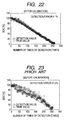
- the test results are shown in Figs. 21 and 22.
- Fig. 21 shows the case with no calibration data used, in which the SOC detection error was as much as 14.9 %
- Fig. 22 shows the case with the calibration data used, in which it was found that the SOC detection error dropped down to 4.1 %, which is a large decrease.
- the input signals may be limited to only data of the voltage history Vi and data of the open-circuit voltage Vo gained when a predetermined amount of power is discharged may be used as calibration data.
- comparative tests were conducted on SOC detection errors of further degraded batteries using two configurations; one was conducted with the use of the above input signal but with no use of the calibration data, while the other was conducted with the use of both the above input signal and the calibration data.
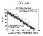
- the test results are shown in Figs. 23 and 24.
- Fig. 23 shows the case with no calibration data used, in which the SOC detection error was as much as 11.3 %
- Fig. 24 shows the case with the calibration data used, in which it was found that the SOC detection error dropped down to 5.3 %, which is a large decrease, like the first modification.
- the on-vehicle battery system adopted in the second embodiment is the same or equivalent as or to that adopted in the first embodiment except for the operations of the correcting signal generator.
- those components which are the same or equivalent as or to those in the first embodiment are given the same reference numerals and omitted from being described in detail. This manner will also be true of the succeeding embodiments.
- the second embodiment adopts a battery state detector 15 with a correcting signal generator 19 which is configured to use a difference ⁇ V between two open-circuit voltages Vo, which is different from the first embodiment.
- a correcting signal generator 19 uses a difference ⁇ V between an open-circuit voltage Vo detected when the battery 1 discharges a predetermined amount of power in its full charge state and an open-circuit voltage Vo detected when the battery 1 is in a substantially full charge state.
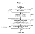
- the correcting signal generator 19 starts its calculation (step S21).
- the generator 19 detects the voltage V and the current I of the battery 1 at intervals (step S22), and then uses the detected voltage V and current I so that the detected values are subjected to a determination whether the battery 1 is in its full charge state (i.e., a full charge determination) (step S23). If it is determined that the battery 1 is in the full charge state, the generator starts integrating the current I to count an integrated current value (Ah) (step 524). Then, the generator 19 then determines whether or not the integrated current value (Ah) reaches a first predetermined threshold which is equivalent to a first discharge amount (step S25). In the present embodiment, the first predetermined threshold is set to a value of 100 to 95 % of the initial SOC.
- a first open-circuit voltage Vo1 to be detected in the almost full charge state is calculated by detecting a y-intercept value of an approximate expression LN obtained in the same way as the first embodiment (step S26).
- the first predetermined discharge amount may be set to a value of zero. In this case, the open-circuit voltage Vo in the exact full charge state can be obtained.
- step S27 the integration of the current is started again (step S27) and it is determined whether or not the integrated current value reaches a second predetermined threshold which is equivalent to a second discharge amount (step S28).
- the second discharge amount is set to be larger than the first discharge amount.
- an approximate expression LN Is estimated to calculate a second open-circuit voltage Vo2 (step S29).
- a difference ⁇ V between the first and second open-circuit voltages Vo1 and Vo2 is calculated by performing Vo2-Vo1 (step S30).
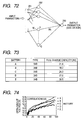
- a test was performed during an actual running on a running mode 10.15.
- the current I and terminal voltage V were measured to figure out Input signals to the neural network calculator, and the calculator learned by using a true value of the SOC (calculated on the integrated current value) as a target output.
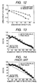
- Fig. 12 shows part of the discharge/open-circuit voltage characteristics of the batteries.
- a value of the voltage difference ⁇ V was used as the calibration data.
- the first discharge amount was 0.5 Ah and the second discharge amount was 5 Ah.
- the results of detection of SOCs are shown in Fig. 13. A difference between the SOC true values and the detected SOC values was estimated as a mean square error, with the result that the error was some 5.7 %.
- the configurations and operations of the system in the third embodiment is essentially the same as those in the foregoing embodiments, but the correcting signal generator and neural network calculator are different in their configurations and operations from the foregoing.
- the on-vehicle battery system according to the present embodiment is provided with a battery state detector 25 with a correcting signal generator 29 and a neural network calculator 17, instead of those shown in the foregoing.
- the correcting signal generator 29 adopts, as calibration data, the internal resistance R of the battery 1 detected when a predetermined amount of power is discharged in the full charge state, in place of the open-circuit voltage detected in discharging a predetermined amount of power in the full charge state.
- the neural network calculator 17 has an output layer 203 outputting data indicative of an SOH (state of health) indicative of a residual capacity, Instead of the SOC (state of charge).
- the calibration data may be composed of data of both of the open-circuit voltage Vo and the internal resistance R which are detected when a predetermined amount of power is discharged in the full charge state.
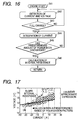
- Fig. 16 shows the processing executed by the correction signal generator 29.
- the processing is started in response to the run of the vehicle (step S41), and the voltage V and current I are detected at intervals (step S42). Then, data of the detected voltage V and current I are used for determining the full charge state (step S43). When it is determined that the battery is In its full charge state, integrating data of the detected data is started to provide a current integrated amount (Ah) (step S44). It is then determined whether or not the current integrated amount reaches a predetermined amount of discharged power (in this embodiment, 5 A), which is a partial consumption of the fully charged power (step S45).
- a predetermined amount of discharged power in this embodiment, 5 A
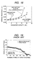
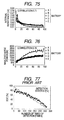
- a relationship between the internal resistance R and an amount of discharged power is shown in Fig. 18 as to some types of used batteries. From Fig. 18, it is revealed that, though an amount of the fully charged power depends on the used batteries, all the used batteries have values which are almost the same at their full charge amounts or thereabouts (that is, in a small range beginning from a discharged amount of 0 Ah). Hence it is difficult to use the internal resistance values R within such a range as indications presenting the degradations. In contrast, as the discharge amount increases, differences among the internal resistance values R are made distinctively larger.
- data of the internal resistance R can be adopted as an input signal, as long as the internal resistance R is estimated after a predetermined amount of power has been discharged from a full charged state (i.e., estimated after a considerable amount of power has beens discharged).
- Such internal resistance values R are thus able to work as distinctive indications for the degradations of batteries, whereby the residual capacity of a battery can be detected with precision.
- the input signals were voltage history data Vi, current history data Ii, a present value of the internal resistance R (i.e., the slope of an approximate expression LN) figured out using the least-squares method, a present value of the open-circuit voltage Vo (i.e., a y-intercept of the approximate expression LN), and a value of the internal resistance R obtained when a predetermined amount of power had been discharged from the fully charged power.
- a present value of the internal resistance R i.e., the slope of an approximate expression LN
- a present value of the open-circuit voltage Vo i.e., a y-intercept of the approximate expression LN
- the on-vehicle battery system is characteristic of performing neutral network calculation to detect information indicative of the SOC (state of charge) and SOH (state of health) by using, as calibration data, both of the open-circuit voltage Vo of a battery 1, which is obtained in response to discharging a predetermined amount of power from the battery 1 which is in full charge, and the internal resistance Ro of the battery 1.
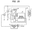
- the on-vehlcle battery system is provided with a battery state detector 35 with a buffer 18, a neural network calculator 27, and a correcting signal generator 39, as shown in Fig. 25.
- the buffer 18 performs the pre-processing of the voltage and current history data Vi and Ii, Additionally, the buffer 18 applies the least-squares method to those voltage and current history data Vi and Ii to create, by a known technique, an approximate expression LN in which the relationship between the voltage and current data V and I is reflected (refer to Fig. 4).
- the buffer 8 uses this approximate expression LN to calculate a value of the y-intercept (i.e., an open-circuit voltage) of the approximate expression LN whenever the voltage and current data V and I are read in so that a present value of the open-circuit voltage Vo of the battery 1 is obtained.
- This present value of the open-circuit voltage Vo which functions as data mutually relating the voltage and current history data Vi and Ii is given to the neural network calculator 7.
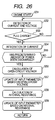
- the correcting signal generator 39 is configured to calculate values of the above open-circuit voltage Vo and the internal resistance R and provide data of those values to the neural network calculator 27 as calibration data. How to calculate those values will now be described with reference to Fig. 26.
- the correcting signal generator 39 starts its calculation (step S51). After the start, the generator 39 detects the voltage V and the current I of the battery 1 at Intervals (step S52), and then uses the detected voltage V and current I so that the detected values are subjected to a determination whether or not the battery 1 is in its full charge state (step S53). The generator 39 then commands to start current integration and determines whether or not an integrated current value (Ah) reaches a predetermined discharge amount (steps S54 and S55).
- a value of the open-circuit voltage Vo which is obtained when such a determination is made, is calculated as an open-circult voltage value Vo to be detected when a predetermined amount of power is discharged (step S56).
- the open-circuit voltage Vo which has been memorized so far is updated to this calculated value (step 557).
- a value of the internal resistance R of the battery 1 is calculated by estimating the slope of the approximate expression LN, as already described (step S58), and the memorized internal resistance R which has been memorized so far is updated to this calculated value (step S59).
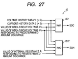
- the neural network calculator 27 is functionally provided with, as shown in Fig. 27, a first neural network block 1071 for calculating an SOC (state of charge) and a second neural network block 1072 for calculating an SOH (state of health).
- these neural network blocks 1071 and 1072 are functionally realized by two sets of processes, in which, for instance, each step is executed set by set at predetermined intervals. More practically, a microcomputer system with a CPU and memories can be used for the neural network calculator 27. Data of the processing, which describe the two sets of processes, are previously stored in a memory and the CPU is capable of performing processing on the described processes.
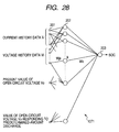
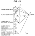
- the first neural network block 1071 for the SOC is functionally depicted in Fig. 28, while the second one 1072 for the SOH is functionally depicted in Fig. 29.
- a difference between the two blocks 1071 and 1072 lies in a configuration in which the input signals (parameters) to the first block 1071 for the SOC does not include a signal of the internal resistance R, but the second block 1072 for the SOH includes the signal of the internal resistance R. Except for the use or non-use of the internal resistance R, both the blocks 1071 and 1072 are the same in their constructions.
- the first block 1071 will now be described as being representative of the first and second blocks 1072 and 1072.
- the first neural network block 1071 for the SOC which is shown in Fig. 28, like the foregoing one, is formed into a three-hierarchical feed-forward type of calculator which learns on a back-propagation technique. This is just one example, however, and any neural network type, if selected properly, can be applied to this block 1071.
- This block 1071 has an input layer 201 with a predetermined number of input cells.
- the respective input cells not only receive, as input data (signals), voltage history data Vi, current history data Il, and present values of the open-circuit voltage Vo and internal resistance R from the buffer 8 but also receive, as calibration data, a value of the open-circuit voltage Vo obtained when the predetermined amount of power is discharged, from the correcting signal generator 39. And the respective Input cells hand the received data to all calculation cells belonging to the Intermediate layer 202.
- the calculation cells in the intermediate layer 202 are in charge of applying neural network calculation to the data to be inputted from the input cells in the input layer 201 and providing resultant calculation results to output cells in the output layer 203. Since the calculation is directed to an SOC, so that the output cells in the output layer 203 produce as output data showing the SOC.
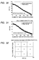
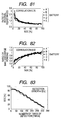
- a first neural network calculator i.e., SOC-dedicated calculator which has learned some charge/discharge patterns (10.15 mode) of some batteries including used batteries was prepared. Another charge/discharge pattern (10.15 mode) for a further used battery was inputted to this calculator, with the neural network calculation performed on the pattern so that an SOC (i.e., charged rate of a battery) was obtained. The results are shown in Fig. 30.
- the input signals to the first neural network calculator are signals showing voltage history data Vi and current history data Ii, and a present value of the open-circuit voltage Vo (i.e., a present value provided by the y-intercept of a least-square approximate expression LN).
- the calibration data was an open-circuit voltage Vo detected in response to discharge of a predetermined amount (0.5 Ah) from the full charge. This test showed a detection error of 1.9 %, which gives a large improvement to the neural network calculation.
- a second neural network calculator i.e., SOH-dedicated calculator which has learned some charge/discharge patterns (10.15 mode) of the group of batteries used in the above test was prepared.
- Another charge/discharge pattern (10.15 mode) for the further used battery which is used in the above test was Inputted to this calculator, with the neural network calculation performed on the pattern so that an SOH Indicating a residual capacity was obtained.
- the results are shown in Fig. 31.
- Test conditions are as follows.
- the input signals to the second neural network calculator are signals showing voltage history data Vi and current history data Ii, a present value of the open-circuit voltage Vo (i.e., a present value provided by the ⁇ -intercept of a least-square approximate expression LN), and a present value of the internal resistance R (i.e., the slope of the least-square approximate expression LN).
- the calibration data were an open-circuit voltage Vo detected in response to a discharge of a predetermined amount of power (e.g., 0.5 Ah) from the full charge and an internal resistance detected R in response to the same discharge. This test showed that a detection error for the SOH was 1.1 Ah, which is largely improved.
- the values of the SOC and SOH calculated above can be classified using a map, which is for example shown in Fig. 32 (in the case of the SOC), and Information showing the degrees of degradation can be provided.
- the degradation degree map shown in Fig. 32 is previously produced and memorized in a memory implemented in the renewal network calculator.
- the exemplified map in Fig. 32 has 12 sections (steps) depending on amounts of the SOC and the full charge capacity Q, so that calculated SOC data are made reference to the degradation degrees of 12 steps to decide into which step the calculated data falls.
- a first modification relates to calculation of the degradation degrees of batteries.
- the degradation degree of a battery can be obtained by calculating "a present value of SOH / (a present value of SOC X Q initial )," wherein Q initial represents an initial full charge capacity of a battery to be tested, which is previously tested and memorized as initial data.
- This kind of calculation can be done by a different calculator communicably connected to the neural network calculator 27 or the calculator 27 itself, whereby the degrees of degradation of each battery can be provided with precision SOC by SOC or SOH by SOH.
- a second modification is shown in Fig. 33, which is concerned with another form of the neural network calculator.
- a neural network calculator 37 functionally shown in Fig. 33 Is configured to have a first neural network block 1071 and a second neural network block 1072A.
- the first neural network block 1071 is the same in configuration as those in Fig, 27, while the second neural network block 1072 receives, as input data, data of the SOC calculated similarly to that in the fourth embodiment, the open-circuit voltage Vo detected in response to a discharge of a predetermined amount, and the internal resistance R detected in response to the discharge.
- the second neural network block 1072 is able to calculate a value of the SOH through learning. Accordingly, the SOH can be calculated at a detection precision which is almost the same as the SOC calculated in the fourth embodiment.
- a third modification is how to supply the input and calibration data.
- the input signals may be limited to only data of the voltage history Vi and the current history Ii and data of the open-circuit voltage Vo and internal resistance R gained when a predetermined amount of power is discharged may be used as calibration data.
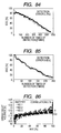
- comparative tests were conducted on SOC detection errors of further used batteries using two configurations; one was conducted with the use of the above input signals but with no use of the calibration data, while the other was conducted with the use of both the above input signals and the calibration data.
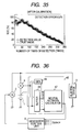
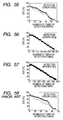
- the test results are shown in Figs. 34 and 35.
- Fig. 34 shows the case with no calibration data used, in which the SOC detection error was as much as 9.1 %
- Fig. 35 shows the case with the calibration data used, in which the SOC detection error dropped down to 6.8 %, which is a large decrease.
- the on-vehicle battery system Is characteristic of performing neutral network calculation to estimate the full charge capacity of a battery 1 by using, as calibration data (part of input signals), both of the open-circuit voltage Vo and internal resistance R of the battery 1, which are obtained when a predetermined amount of power is discharged from the fully charged power.
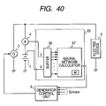
- the on-vehicle battery system is provided with a battery state detector 45 with a buffer 28, a neural network calculator 47, and a correcting signal generator 49, as shown in Fig. 36.
- the battery state detector 45 can be formed, as a whole or in part, into a microcomputer with a CPU, memories and other necessary parts, not limited to circuitry on digital logic circuits and/or analog circuits.
- the circuitry shown in Fig. 36 is just an illustrative example.
- the neural network calculator 47 is configured to receive various input signals from the buffer 28 and correcting signal generator 49 and applies neural network calculation to the those input signals to estimate, as its output parameter, data indicative of to a full charge capacity Q to be expected of the battery 1.
- the correcting signal generator 49 is configured to calculate, as calibration data, an open-circuit voltage Vo and an internal resistance R of the battery 1 which are obtained in response to discharging a predetermined amount of power from the battery 1 having the fully charged power. If this generator 49 is functionally realized by a microcomputer system, a CPU will calculate the open-circult voltage Vo and internal resistance R from a group of voltage and current pairs V and I held in a RAM or registers.
- the buffer 28 is formed to be engaged exclusively in the processing of voltage and current data V and I to be received, including parallel sampling of those two types of data at intervals to form voltage and current history data Vi and Ii, storage thereof, and parallel output of the voltage and current data V and I at each sampling time to the neural network calculator 47.
- the correcting signal generator 49 is configured such that it calculates the open-circuit voltage Vo and internal resistance R of the battery 1 detected in response to discharging an amount of power from the battery 1 having a fully charged power.
- Data showing values of those open-circuit voltage Vo and internal resistance R are supplied to the neural network calculator 47 as calibration data.
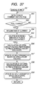
- the processing for this data supply is shown in Fig. 37, which is similar in contents to those in Fig. 26.
- the correcting signal generator 49 starts its calculation (step S51'). After the start, the generator 49 detects the voltage V and the current I of the battery 1 at intervals (step S52'), and then uses the detected voltage V and current I so that the detected values are subjected to a determination whether or not the battery 1 is in its full charge state (step S53'). The generator 39 then commands the start of current integration and determines whether or not an integrated current value (Ah) reaches a predetermined discharge amount (steps S54' and S55').
- a value of the open-circuit voltage which is obtained when such a determination is made, is calculated as an open-circuit voltage value Vo to be detected when a predetermined amount of power is discharged (step S56').
- the open-circuit voltage which has been stored so far is updated to this new calculated value (step S57').
- a value of the internal resistance R of the battery 1 is calculated by estimating the slope of the approximate expression LN, as already described (step S58'), and the internal resistance R which has been stored so far is also updated to this new calculated value (step S59').
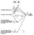
- the neural network calculator 47 has an input layer 201 with input cells 201, intermediate layer 202 with calculation cells, and output layer 203 with an output cell.
- the input cells of the input layer 201 receive, from the buffer 28, as input signals, both the voltage history data Vi and the current history data Il and also receives, from the correcting signal generator 49, as calibration data, the data of the open-circuit voltage Vo and the internal resistance R both responding to a discharge of a predetermined amount of power.
- the received data by the input cells are handed, respectively, to the calculation cells of the intermediate layer 202.
- the respective cells perform predetermined neural network calculation on the input data handed from the input cells so that a full charge capacity Q to be expected currently of the battery 1 is estimated.
- a degree of degradation of the battery 1 which can be functionally established by either the neutral network calculator 47 or the generator control unit 6, shown in Fig. 36.
- a degree of degradation of the battery 1 Q present / Q initial
- DD denotes a degree of degradation of the battery 1
- Q present denotes a present value of the full charge capacity estimated by or in the neural network calculator 47
- Q initial denotes an initial value of the full charge capacity previously given to the system.
- on-vehicle lead batteries were employed, which each have an initial full charge capacity of 27 Ah and whose degraded states were different from each other.
- the full charge capacity of each battery at present was measured in the form of a current-integrated value obtained by Integrating current to be detected on condition that a discharge was conducted until the terminal voltage decreased from the value corresponding to the full charge state down to 10.5 V under a discharge condition of 0.2CA.
- These batteries which have been discharged under the above conditions were connected to the on-vehicle neural network calculator and its vehicle was made run under a 10.15 running mode, In which the neural network calculation was executed to estimate the full charge capacity Q.
- a predetermined amount of power to detect the open-circuit voltage Vo and internal resistance R was 5.0 Ah, which was consumed from the fully charged state.
- Data of the voltage and current history VI and Il were five pairs of voltage and current sampled at intervals during a predetermined period of time just before the neural network calculation.
- an error detecting the full charge capacity for each battery was estimated using data acquired during a period of time lapsing from completion of a discharge of 5.0 Ah to the end of the running. The errors were expressed as mean values and are shown as in Table 1. (Table 1) Test piece No.
- the predetermined amount of power is set to a value that corresponds to a discharge of 0 to 30 % of the initial (rated) full charge capacity of the battery form a present full charge power thereof.
- the predetermined amount of power is set to a value that corresponds to a discharge of 2 to 20 %. Particularly, it is still preferable to set to a value that corresponds to a discharge of 3 to 10 %.
- the Input parameters include, at minimum, voltage history data, current history data, an open-circuit voltage responding to a predetermined-amount discharge, and an Internal resistance responding to the predetermined-amount discharge.
- other parameters indicating battery states may be included in the input parameters.
- adding other parameters to the foregoing minimum Input parameters should be limited to an extent that allows an increase in the calculation amount is within a 50 % thereof.
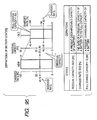
- the on-vehicle battery system is characteristic of neural network calculation conducted with use of a plurality of memory tables In which coupling coefficients (i.e., matrices) are listed, group by group, depending on values of input parameters.
- the on-vehicle battery system is provided with a battery state detector 55 with a buffer 38 and a neural network calculator 57.
- the correcting signal generator descried in the foregoing various embodiments is not implemented.
- This battery state detector 55 is also functionally realized, for instance, as descried, but this is not a definitive list.
- the buffer 38 samples pairs of voltage V and the current I and use the sampled data to create not only data of voltage history Vi and current history Il but also an open-circuit voltage Vo, all of which are given to the neural network calculator 57 as input parameters.
- the voltage and current history data VI and Il may be replaced by pairs of an average voltage Va and an average current Ia, described already.
- an internal resistance R of the battery 1 may be used as part of the input parameters. The open-circuit voltage Vo and the internal voltage R can be obtained in the same technique as described.
- the neural network calculator 57 is in charge of performing determination whether or not the battery 1 is in its fully charged state and neural network calculation using a plurality of memory tables for coupling coefficients.
- the determination as to the fully charged state is the same as described in the first embodiment (refer to Fig. 3).
- the open-circuit voltage detected when the battery 1 is in its fully charged state is denoted by Vo full , as described.
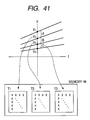
- the neural network calculator 57 learning is made beforehand based on input parameters of a range including the value of the open-circuit voltage Vo full in the fully charged state, and a coupling-coefficient memory table is selected from a memory M internally installed or externally connected in or to this calculator 57. Hence, the neural network calculation will be made using this selected coupling-coefficient memory table.
- the memory M stores therein a plurality of coupling-coefficient memory tables T1 - T3 in which coupling coefficients are written for every voltage range A (to C) decided depending on values of the open-circuit voltage Vo full , that is, depending on the amplitude thereof.
- the coupling-coefficient memory tables T1 - T3 are set for the respective voltage ranges on one-to-one correspondence, beforehand.
- the coupling coefficients stored in each memory table Ti are coupling coefficients calculated on the basis of the input parameters obtained from a learning battery that has an open-circuit voltage Vo full residing within any of the voltage ranges. When it is determined that a fully charged state has yet to be realized, the neural network calculation is made without updating the coefficients in the memory tables.
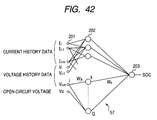
- Fig. 42 functionally shows the configuration of the neural network calculator 57 having an input layer 201, intermediate layer 202, and output layer 203, cells of those layers are mutually connected with each other in the similar manner to those already described.
- the neutral network calculator 57 is able to perform a specified type of neutral network calculation using the input parameters of current history data (Ii, Ii-1, ..., Ii-m), voltage history data (Vi, Vi-1, ..., Vi-m), and an open-circuit voltage Vo given to the input cells of the input layer 201 and coupling coefficients Wjk and Wk to be updated to minimize an error function, as described In the first embodiment.
- the calculation is conducted to allow the output layer 203 to output, as an output parameter, an SOC (state of charge), for example.
- pairs of voltage V and current I which compose voltage and current history data VI and Il, are inputted to the buffer 38 and an open-circuit voltage Vo is calculated in the buffer 38, and their data are inputted as input parameters to the neural network calculator 57 (steps S61-S63).
- step S64 it is determined whether or not the battery 1 is in its fully charged state (step S64).
- the open-circuit voltage Vo full is calculated to select a coupling-coefficient memory table Tl depending on the value (magnitude) of the open-circuit voltage Vo full (step S65; refer to Fig. 41). That is, it is decided that the calculated value of the open-circuit voltage Vo full falls into which voltage range A (to C), and then a coupling-coefficient memory table Ti corresponding to the calculated voltage value is automatically specified. Thus, coupling coefficients stored In the specified coupling-coefficient memory table Ti are read out.
- the neural network calculator 57 performs neural network calculation on the read-in coupling coefficients so as to estimate an SOC (state of charge) indicative of a charged rate of a battery. Data of the resultant SOC is then outputted, as an output parameter, from the neural network calculator 57 to, for example, the generator control unit 6.
- an Internal resistance R or any other quantities may be added to a group of input parameters to be used in neural network calculation.
- the internal resistance R or other quantities may be calculated at step 563, together with the open-circuit voltage Vo.
- a further variation is to employ an SOH (state of health) indicative of a residual capacity of a battery, Instead of the SOC.
- the first battery group was composed of five batteries whose open-circuit voltages Vo full were 12.1 V or more but less than 12.4 V
- the second battery group was composed of five batteries whose open-circuit voltages Vo full were 12.4 V or more but less than 12.8 V
- the third battery group was composed of five batteries whose open-circuit voltages Vo full were 12.8 V or more but less than 13.2 V.
- the respective batteries were mounted, by turns, on the same vehicle and subjected to measurement of current I and terminal voltage V thereof in the running mode 10.15. Then, using the measurements, an open-circuit voltage Vo was calculated. SOCs were then calculated through the foregoing neural network calculation, and coupling-coefficient memory tables were produced group by group, whereby three coupling-coefficient memory tables were obtained in which coupling coefficients for the neural network calculation were written group by group.
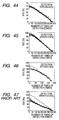
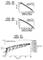
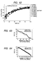
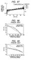
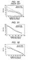
- Fig. 44 shows a graph showing calculated (measured) results of the SOC obtained from a battery whose open-circuit voltage Vo full is 12.25 V, the results being calculated with the use of the first coupling-coefficient memory table whose coupling coefficients leaned the charge/discharge pattern given by the first battery group.
- Fig. 45 shows a graph showing calculated (measured) results of the SOC obtained from a battery whose open-circuit voltage Vo full is 12.6 V, the results being calculated with the use of the second coupling-coefficient memory table whose coupling coefficients leaned the charge/discharge pattern given by the second battery group.
- Fig. 44 shows a graph showing calculated (measured) results of the SOC obtained from a battery whose open-circuit voltage Vo full is 12.25 V, the results being calculated with the use of the first coupling-coefficient memory table whose coupling coefficients leaned the charge/discharge pattern given by the first battery group.
- Fig. 45 shows a graph showing calculated (measured) results of the
- an open-circuit voltage Vo detected in response to a discharge of a predetermined amount of power from a battery which has been fully charged may be used instead of the open-circuit voltage Vo full .
- an open-circuit voltage Vo detected in response to a discharge of a predetermined amount of power from a battery which has been fully charged may be used.
- a plurality of coupling-coefficient memory tables are set similarly to the above.
- an internal resistance R of a batter may be used solely instead of the voltage Vo full .
- a combination of an open-circuit voltage Vo and an internal resistance R may be used on behalf of the voltage Vo full .
- the open-circuit voltage Vo full is set.
- no consideration is taken into the influence of polarization in the open-circuit voltage Vo full and/or the internal resistance R.
- the open-circuit voltage Vo full and/or the Internal resistance R may be decided such that their values are reduced In consideration of the influence of the polarization voltage.
- the resultant voltage Vo full and/or resistance R are usable for respectively assigning coupling coefficients to the memory tables.
- the on-vehicle battery system is characteristic of preventing a calculation load from increasing and a circuitry size from enlarging, while still securing high precision in detecting one or more desired output parameters indicating the charged state of an on-vehicle battery.
- the on-vehicle battery system is provided with a battery state detector 65 with a buffer 48 and a neural network calculator 67, but with no correcting signal generator employed by the first to third embodiments.
- the battery state detector 65 is functionally realized by, for example, a computer system with a microcomputer, memories and other necessary elements.
- the buffer 48 is configured to perform the following various types of processing.
- the buffer 48 reads in data of voltage (terminal voltage) V of the battery 1 and data of current I from the current sensor 4, in real time, at Intervais, for simultaneous sampling thereof, and memorizes sampled data composed of pairs of voltage V and current I. Moreover, the buffer 48 uses those pairs of voltage V and current I to specified types of functional values consisting of average voltage Va, average current Ia, open-circuit voltage Vo, internal resistance R, a correlation function value f (Vo, R) showing an amount of dischargeable current.
- the average voltage Va is an average of the voltages V of the battery 1 over the latest interval of calculation time and the average current Ia is an average of the charged and discharged currents I in and from the battery 1 detected during the latest interval of calculation time.
- These values Va and Ia may be outputs of low-pass filters into which the data of the voltage V and current I are supplied, respectively.
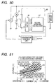
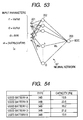
- the open-circuit voltage Vo and internal resistance R are calculated using a two-dimensional map in which the average voltage Va and average current Ia are two-dimensionally mapped (refer to Fig. 51). Each pair of average voltage Va and average current Ia undergo calculation on a least-squares method to figure out a linearly approximate expression L. The y-intercept and slope of this expression indicate an open-circuit voltage Vo and an internal resistance R of the battery 1. Thus, based on the linearly approximate expression L, data indicative of an open-circuit voltage Vo and an Internal resistance R are calculated every time when the pairs of average voltage Va and average current Ia are inputted.
- the value Pm shows a power which is expressed as a function having a positive correlation to an amount of power dischargeable of the battery 1 at present.
- the buffer 48 further calculates "full charge ratios" of the average voltage Va, open-circuit voltage Vo, internal resistance R, and correlation functional value f (Vo, R), respectively.
- the "full charge ratio” is provided to each of those physical quantities and defined as a ratio of a present value of each physical quantity to a value thereof obtained in the fully charged state of the battery 1. These full charge ratios exhibit higher correlations with degrees of degradations of batteries, which are therefore proper for input parameters for correcting (calibrating) charged states of each battery which are on account of the degradations.
- the buffer 48 calculates and memorizes a full-charge average voltage Vaf showing an average voltage Va to be estimated at the last fully charged state, a full-charge open-circuit voltage Vof showing an open-circuit voltage Vo to be estimated at the last fully charged state, a full-charge internal resistance Rf showing an internal resistance R to be estimated at the last fully charged state, and a full-charge correlation function value f (Vof, Rf) showing a correlation function value f (Vo, R) to be estimated at the last fully charged state. Then, values of those physical quantities are read out from a memory to make a comparison with present values thereof, respectively, which have been calculated at present.
- ratios of Va/Vaf, Vo/Vof, R/Rf, and (Vo.Vo/R)/ (Vof ⁇ Vof/Rf) are figured out as part of input parameters to the neural network calculator 67.
- the ratio of (Vo ⁇ Vo/R)/(Vof ⁇ Vof/Rf) is thus a power ratio.
- the calculation of the full-charge average voltage Vaf, full-charge open-circuit voltage Vof, full-charge internal resistance Rf, and full-charge correlation function value f (Vof, Rf) involves determination as to whether or not the battery 1 is now in its full charge state. This determination is also carried out In the similarly to that explained in the first embodiment (refer to Fig. 3). That is, the voltage V and current I in Fig. 3 should be read as the average voltage Va and average current Ia. Pairs of average voltage Va and average current Ia are thus subjected to determination such that a coordinate point specified by each pair falls into a predetermined region to show the fully charged state in the two-dimensional map.
- Those full-charge related physical quantities are memorized in a memory and updated whenever the full charge determination is made.
- Fig. 52 outlines the processing carried out by the battery state detector 65 (i.e., the buffer 48 and calculator 67).
- the calculated (that is, estimated) SOC are outputted to the generator control unit 6 (step S76).
- any other parameters, which are selected properly, may be added to the input parameters.
- the ratio r4 is a power ratio relating to a full charge.
- the output parameter may be an SOH showing a residual capacity, i.e., a present capacity available for discharge.
- the neural network calculator 67 is therefore allowed to learn charge/discharge patterns of some typical types of batteries, as described in connection with Fig. 6, prior to the shipment of the on-vehicle battery system. As a result, regardless of fluctuations in manufacturing each on-vehicle battery, the SOC of the on-vehicle battery can be estimated with precision through the neural network calculation during each run of the vehicle.
- this neural network calculator which had completed the leaning was used to calculate an SOC of each of further used batteries to be tested which were variously degraded in their performances.
- the tested results were compared to the current integrated results, which are shown in Figs. 55 to 60.
- Figs. 55 to 57 show the SOCs of three batteries to be tested, respectively, with the use of the five input parameters consisting of Va, Vo, R, Ia, and (Vo ⁇ Vo/R)/ (Vof ⁇ Vof/Rf).
- Figs. 55 to 57 show the SOCs of three batteries to be tested, respectively, with the use of the five input parameters consisting of Va, Vo, R, Ia, and (Vo ⁇ Vo/R)/ (Vof ⁇ Vof/Rf).
- a group of further nine batteries were subjected to testing a correlation between their ratios of Vo/Vof and their SOCs.
- the tested results are indicated in Fig. 61, which reveals a correlation of 0.86.
- another group of further nine batteries one of which was brand new, were also subjected to testing a correlation between their full-charge power ratios of (Vo ⁇ Vo/R)/(Vof ⁇ Vof/Rf) and their SOCs.
- the tested results are indicated in Fig. 62, which reveals a correlation of 0.93. From the results in Fig. 62, it is found that the addition of the above power ratio, which has a larger correlation as above, to the input parameters raises the precision of the SOC calculation, compared to the mere use of the open-circuit voltage Vo.
- the foregoing configuration can be modified as follows.
- the hardware configuration is the same as that described above, but the input parameters differ from the above,
- a full-charge related current ratio defined by Im (Vm-Vo)/R also serving as the correlation function value f(Vo, R).
- This current Im represents chargeable current at present.
- the voltage Vm which is a predetermined final voltage at which the charge stops, was set to 10.5 V.
- the relationship between the discharge stop voltage Vm and the chargeable current Im is shown in Fig. 51.
- the function value f(Vo, R) may be set to have a correlation with a function value Vo ⁇ Vo/R.
- this neural network calculator which had completed the leaning was used to calculate an SOC of each of further used batteries to be tested which were variously degraded in their performances.
- the tested results were compared to the current integrated results, which are shown in Figs. 63 to 68.
- Figs. 63 to 65 show the SOCs of three batteries to be tested, respectively, with the use of the five input parameters consisting of Va, Vo, R, Ia, and [(Vm-Vo)/R]/[(Vm-Vof)/Rf].
- Figs. 63 to 65 show the SOCs of three batteries to be tested, respectively, with the use of the five input parameters consisting of Va, Vo, R, Ia, and [(Vm-Vo)/R]/[(Vm-Vof)/Rf].
- the on-vehicle battery system is characteristic of preventing a calculation load from Increasing and a circuitry size from enlarging, while still securing high precision in detecting one or more desired output parameters indicating the charged state of an on-vehicle battery.
- the on-vehicle battery system has circuitry shown in Fig. 69, In which there is provided a battery state detector 75 with a buffer 58 and a neural network calculator 77. Like the foregoing, the battery state detector 75 can be established functionally by processing on a microcomputer, but a dedicated hardware circuit may be used as well.
- a predetermined amount of power for example 1.4 Ah
- step S85 various types of ratios of Vat/Vaf, Vot/Vof, Rt/Rf, and Pt/Pf are calculated as input parameters to the neural network calculator 77.
- the processing is then stopped until the timing at which the next pair of voltage and current data are sampled.
- step S83 4 It is then determined whether or not the current integrated value (i.e., discharged value) Ah has reached a predetermined threshold Ahth (step S83 4 ).
- the buffer 58 recognizes the discharge of the predetermined amount of power from the fully charged state.
- the predetermined amount of power used for the above determination is set to a value corresponding to a discharge of 5 % of the Initial full charge capacity, from the fully charged state to be realized at present.
- this is not a definitive list.
- the inventors' various experiments show that any discharge of small amounts of power may be used as the reference to the threshold Ahth.
- Fig. 72 shows the functional configuration of the neural network calculator 77, which receives the input parameters consisting of data of the ratios of Vat/Vaf, Vot/Vof, Rt/Rf, and Pt/Pf and provides as an output parameter an SOC or SOH indicating a charged state quantity of the battery 1.
- the input parameters are not limited to those four ratios, but may be parameters including the ratio of Vat/Vaf and at least one of the ratios of Vot/Vof, Rt/Rf, and Pt/Pf.
- the operations of the neural network calculator 77 are identical to those described (Fig. 6).
- the neural network calculation is able to take battery degradation degrees into consideration, estimating the output parameter with precision.
- the ratio taken into the input parameters can be limited to one or two among the circuit-open voltage Vo, internal resistance R, and maximum discharge power P.
- the remaining quantities other than being taken in the form of ratios can be taken in the form of present values.
- the present values may be multiplied by a constant or may be subjected to addition or subtraction with a constant.
- Batteries A to E for learning which are shown in Fig. 73, were operated on a predetermined charge and discharge pattern (on the 10.15 running mode), so that a neural network calculator learned the relationships between input parameters and an output parameter (SOC) of these batteries A to E.
- Figs. 74, 75 and 76 show, as to the respective batteries A to E, the relationships between the open-circuit voltages Vo and the SOCs, the relationships between the internal resistances R and the SOCs, and the relationships between the maximum discharge powers P and the SOCs, respectively.
- the foregoing batteries A to E were operated under the predetermined charge and discharge pattern on the 10.15 running mode so that the neural network calculator learned the relationships between the input parameters and the output parameter (SOC) of the respective batteries A to E.
- the input parameters were four ratios to be described later.
- Vat, Vot, Rt and Pt of the average voltage Va, open-circuit voltage Vo, internal resistance R, and maximum charge power P were used to compute four ratios of Vat/Vaf, Vot/Vof, Rt/Rf and Pt/Pf, which were input parameters to the neural network calculator.
- This calculator calculated an SOC on the neural network calculation on the input parameters.
- Fig. 80 shows the correlation between the ratio of Vot/Vof and the SOC
- Fig. 81 shows the correlation between the ratio of Rt/Rf and the SOC
- Fig. 82 shows the correlation between the ratio of Pt/Pf and the SOC. It was found from these figures that each ratio has a good correction to the SOC, in particular, the ratios of Vot/Vof and Rt/Rf have a higher correlation to the SOC.
- the foregoing ratios or respective values can be multiplied by a specified constant.
- a specified constant may be added to the respective ratios or subtracted from each of the respective ratios.
- Figs. 83 to 85 provide the test results, in which Fig. 83 shows a calculation result of the SOC of the first tested battery, Fig. 84 shows that of the second tested battery, and Fig. 85 shows that of the third tested battery. Mean square errors to the calculation of the SOCs of the first to third tested batteries were 4.3 %, 6.7 % and 3.9 %, respectively.
- the average voltage Va is adopted in the form of the ratio to the discharge of the predetermined amount of power, but this average voltage Va may be used as it is, that is, without being the ratio, because an increase in the error was not so large in the case of not using the ratio of the average voltage Va.
- either a present value of the average current Ia or a ratio of Ia/If may be added, wherein If is a value of the average current acquired in response to a discharge of a predetermined amount of power from the full charge power. In this parameter configuration, a further decrease in the error was gained.
- the input parameters may include data of voltage and current history, which is also effective for attaining a larger decrease in the detection (i.e., estimation) error.
- Vot is a correcting open-circuit voltage to be inputted as an input parameter to the neural network calculator 77
- Vot is a present value of the open-circuit voltage Vo
- ⁇ and ⁇ are coefficients smaller than 1
- Vof1 is a value of the open-circuit voltage Vo acquired in response to a discharge of 1 Ah (corresponding to 5 % of the initial (rated) full charge capacity) from the last-time full charge power
- Vof2 is a value of the open-circuit voltage Vo acquired in response to a discharge of 5 Ah (corresponding to 25 % of the initial (rated) full charge capacity) from the last-time full charge power.
- the open-circuit voltage Vot' to be applied to the neural network calculator 77 consists a linear function whose variables are a present value of the open-circuit voltage Vo and values Vof1 and Vof2 of the open-circuit voltage Vo acquired in response to discharging predetermined amounts of power from the full charge power
- the open-circuit voltage Vo is corrected with the use of the linear function, with the result that the correlation between the open-circuit voltage Vo and the SOC can be improved.
- Fig. 86 shows the correlations between present values Vot of the open-circuit voltages Vo of three batteries to be tested and the SOCs thereof and Fig. 87 shows the correlations of values of the corrected open-circuit voltages Vot' of those three batteries and the SOC thereof. From the comparison between these figures, irrelevantly of fluctuations in the degraded states and initial characteristics of batteries to be tested, fluctuations in both the corrected open-circuit voltages Vot' and the SOC can be suppressed largely.
- Batteries A to E for learning which are shown in Fig. 73, were operated on a predetermined charge and discharge pattern (on the 10.15 running mode), so that a neural network calculator learned the relationships between input parameters and an output parameter (SOC) of these batteries A to E.
- the input parameters were data of voltage and current history and an open-circuit voltage Vo.
- the voltage and current data consist of pairs of voltage and current data sampled at intervals during the latest predetermined period of time.
- the foregoing batteries A to E were tested under the same charge and discharge pattern on the 10.15 running mode so that the neural network calculator learned the relationships between input parameters and an output parameter (SOC) of those batteries A to E.
- the input parameters were data of the voltage and current history and the corrected open-circuit voltage Vot'.
- the corrected open-circuit voltage Vot' was obtained such that the open-circuit voltage Vo in response to respectively discharging amounts of 1 Ah and 5 Ah from a full charge power gave Vof1 and Vof2 were memorized as new ones. These values Vof1 and Vof2 were used, together with a present value Vot of the open-circuit voltage Vo, to calculate the linear corrected open-circuit voltage Vot'.
- the data of the resultant voltage Vot' and the voltage and current history were fed to the neural network calculator to estimate the SOC.
- the results are shown in Figs. 91 to 93, which respectively provide the results of calculation of the SOC of the first to third batters which were tested. As shown in those figures, mean square errors in estimating the SOC were 8.0 %, 9.4 % and 8.1 %, respectively.
- the correction based on the linear correcting function will not be limited to the open-circuit voltage Vo described above, but this manner may be adopted for the internal resistance R and/or maximum discharge power P.
- the corrected values R and/or P can be used as input parameters as well.
- an average voltage and/or an average current may be employed as part of the input parameters.
- Another modification is concerned with the number of open-circuit voltages used for determining the linear correcting function. That is, the number of voltages is not always limited to two, but a signal open-circuit voltage may be adopted or three or more ones may be adopted.
- Another modification is to use of parameters coming from both the correction based on the ratios described in the embodiment and the correction based on the linear correction functions described in the modification in a combined manner, as to the open-circuit voltage Vo, Internal resistance R and maximum discharge power P, all of which are quantities closely related to a degraded state of each battery.
- the open-circuit voltage Vo, Internal resistance R and maximum discharge power P may be modified such that those values are first subjected to the linear function correction described in the modification and the corrected values are then processed to produce, as a whole or in part, Input parameters based on the ratios described in the embodiment.
- a voltage V and/or an open-circuit voltage Vo which are part of the input parameters, may be linearly converted to a function.
- the voltage V may be converted to K1 ⁇ V+k2, wherein K1 and K2 are constants.
- An output error to be caused by a difference between an input parameter V and an input parameter K1 ⁇ V+k2 can be converged to be almost zero readlly through the neural network calculation.
Landscapes
- Physics & Mathematics (AREA)
- Engineering & Computer Science (AREA)
- General Physics & Mathematics (AREA)
- Chemical & Material Sciences (AREA)
- Combustion & Propulsion (AREA)
- Mechanical Engineering (AREA)
- Thermal Sciences (AREA)
- General Engineering & Computer Science (AREA)
- Secondary Cells (AREA)
Applications Claiming Priority (6)
| Application Number | Priority Date | Filing Date | Title |
|---|---|---|---|
| JP2005036437A JP4609882B2 (ja) | 2005-02-14 | 2005-02-14 | 車両用蓄電装置の内部状態検出方式 |
| JP2005036442A JP4587299B2 (ja) | 2005-02-14 | 2005-02-14 | 車両用蓄電装置の内部状態検出方式 |
| JP2005039614A JP4609883B2 (ja) | 2005-02-16 | 2005-02-16 | 車両用蓄電装置の満充電容量演算装置 |
| JP2005122004A JP4582583B2 (ja) | 2005-04-20 | 2005-04-20 | 二次電池の残存容量演算方法 |
| JP2005122011A JP2006300692A (ja) | 2005-04-20 | 2005-04-20 | 二次電池の残存容量演算方式 |
| JP2005151059A JP4582584B2 (ja) | 2005-05-24 | 2005-05-24 | 二次電池の残存容量演算方法 |
Publications (2)
| Publication Number | Publication Date |
|---|---|
| EP1691209A1 true EP1691209A1 (fr) | 2006-08-16 |
| EP1691209B1 EP1691209B1 (fr) | 2008-10-01 |
Family
ID=36401703
Family Applications (1)
| Application Number | Title | Priority Date | Filing Date |
|---|---|---|---|
| EP06002917A Active EP1691209B1 (fr) | 2005-02-14 | 2006-02-14 | Procédé et appareil de détection de l'état de charge d'une batterie de secours, basés sur un calcul de réseau neuronal |
Country Status (4)
| Country | Link |
|---|---|
| US (1) | US7554296B2 (fr) |
| EP (1) | EP1691209B1 (fr) |
| KR (1) | KR100880717B1 (fr) |
| DE (1) | DE602006002896D1 (fr) |
Cited By (20)
| Publication number | Priority date | Publication date | Assignee | Title |
|---|---|---|---|---|
| FR2906892A1 (fr) * | 2006-10-10 | 2008-04-11 | Peugeot Citroen Automobiles Sa | Systeme d'evaluation de l'etat de fonctionnement d'une batterie de vehicule automobile |
| WO2008068446A1 (fr) * | 2006-12-06 | 2008-06-12 | Iti Scotland Limited | Système de gestion de batterie |
| WO2009025512A2 (fr) | 2007-08-23 | 2009-02-26 | Lg Chem, Ltd. | Système et procédé d'estimation de caractéristiques à long terme d'accumulateur |
| EP2359128A1 (fr) * | 2008-11-17 | 2011-08-24 | Otis Elevator Company | Calibration de l état de charge d une batterie |
| CN103323778A (zh) * | 2012-03-21 | 2013-09-25 | 古河电气工业株式会社 | 二次电池状态检测装置以及二次电池状态检测方法 |
| FR2999721A1 (fr) * | 2012-12-18 | 2014-06-20 | Batscap Sa | Procede et dispositif de caracterisation d'un module de stockage d'energie par effet capacitif. |
| EP2975421A1 (fr) * | 2014-07-18 | 2016-01-20 | Samsung Electronics Co., Ltd | Procédé et appareil pour l'estimation de l'état d'une batterie |
| CN105334463A (zh) * | 2014-08-08 | 2016-02-17 | 中兴通讯股份有限公司 | 电池电量检测方法、系统及电池 |
| CN106033113A (zh) * | 2015-03-19 | 2016-10-19 | 国家电网公司 | 一种储能电池组健康状态评估方法 |
| CN108051746A (zh) * | 2017-11-02 | 2018-05-18 | 福建联迪商用设备有限公司 | 一种电池正常供电的判断方法及终端 |
| US20190170826A1 (en) * | 2017-12-06 | 2019-06-06 | Cadex Electronics Inc. | Battery state-of-health determination upon charging |
| CN110133507A (zh) * | 2019-04-23 | 2019-08-16 | 杭州电子科技大学 | 一种基于narx-ukf算法的电池剩余电量估计方法 |
| EP3451004A4 (fr) * | 2017-01-02 | 2019-09-11 | LG Chem, Ltd. | Dispositif et procédé de gestion de batterie pour étalonner l'état de charge d'une batterie |
| CN111061151A (zh) * | 2019-11-21 | 2020-04-24 | 东北大学 | 一种基于多元卷积神经网络的分布式能源状态监测方法 |
| CN111142026A (zh) * | 2019-12-31 | 2020-05-12 | 联想(北京)有限公司 | 一种数据处理方法、装置及电子设备 |
| DE102019107935A1 (de) * | 2019-03-27 | 2020-10-01 | Volkswagen Aktiengesellschaft | Verfahren zur Bestimmung eines Zustands einer wiederaufladbaren Batterie eines Fahrzeuges |
| CN112540303A (zh) * | 2020-11-18 | 2021-03-23 | 潍柴动力股份有限公司 | 一种校正方法及装置 |
| US20210091583A1 (en) * | 2018-06-08 | 2021-03-25 | Panasonic Intellectual Property Management Co., Ltd. | Battery management system and battery management method |
| US11205912B2 (en) | 2017-07-25 | 2021-12-21 | Semiconductor Energy Laboratory Co., Ltd. | Power storage system, electronic device, vehicle, and estimation method |
| US11480621B2 (en) | 2017-11-02 | 2022-10-25 | Semiconductor Energy Laboratory Co., Ltd. | Capacity estimation method and capacity estimation system for power storage device |
Families Citing this family (102)
| Publication number | Priority date | Publication date | Assignee | Title |
|---|---|---|---|---|
| US7429849B2 (en) * | 2003-11-26 | 2008-09-30 | Toyo System Co., Ltd. | Method and apparatus for confirming the charge amount and degradation state of a battery, a storage medium, an information processing apparatus, and an electronic apparatus |
| KR100669434B1 (ko) * | 2005-04-07 | 2007-01-15 | 삼성에스디아이 주식회사 | 이차 전지 모듈 제어방법 |
| KR100717789B1 (ko) | 2005-07-29 | 2007-05-11 | 삼성에스디아이 주식회사 | 이차 전지 모듈의 전지 잔존용량 산출방법 |
| KR100740097B1 (ko) * | 2005-10-20 | 2007-07-16 | 삼성에스디아이 주식회사 | 배터리의 soc 추정 방법 및 이를 이용한 배터리 관리시스템 |
| KR100739054B1 (ko) * | 2005-10-20 | 2007-07-12 | 삼성에스디아이 주식회사 | 배터리 관리 시스템 및 배터리의 셀 전압 측정방법 |
| KR100796668B1 (ko) * | 2006-09-26 | 2008-01-22 | 삼성에스디아이 주식회사 | 배터리 관리 시스템 및 그의 구동 방법 |
| KR100859688B1 (ko) * | 2006-10-12 | 2008-09-23 | 삼성에스디아이 주식회사 | 배터리 관리 시스템 및 그의 구동 방법 |
| KR100814884B1 (ko) * | 2006-10-16 | 2008-03-20 | 삼성에스디아이 주식회사 | 배터리 관리 시스템 및 그 구동방법 |
| KR100839381B1 (ko) * | 2006-11-01 | 2008-06-20 | 삼성에스디아이 주식회사 | 배터리 관리 시스템 및 그 구동방법 |
| US7982432B2 (en) * | 2006-12-22 | 2011-07-19 | Gm Global Technology Operations, Llc | Method and system for monitoring an electrical energy storage device |
| JP4811301B2 (ja) * | 2007-03-06 | 2011-11-09 | トヨタ自動車株式会社 | 二次電池の入出力制御装置、および車両 |
| KR100882913B1 (ko) * | 2007-03-19 | 2009-02-10 | 삼성에스디아이 주식회사 | 배터리 팩 |
| JP2008232758A (ja) * | 2007-03-19 | 2008-10-02 | Nippon Soken Inc | 二次電池の内部状態検出装置及びニューラルネット式状態量推定装置 |
| US7830119B2 (en) | 2007-08-29 | 2010-11-09 | Gm Global Technology Operations, Inc. | Adaptive battery estimator and method |
| KR100936892B1 (ko) * | 2007-09-13 | 2010-01-14 | 주식회사 엘지화학 | 배터리의 장기 특성 예측 시스템 및 방법 |
| DE102008058292B4 (de) * | 2007-11-21 | 2018-04-05 | Denso Corporation | Verfahren und Vorrichtung zur Detektion des internen elektrischen Zustands einer Fahrzeugsekundärbatterie |
| US8283891B2 (en) * | 2008-03-21 | 2012-10-09 | Rochester Institute Of Technology | Power source health assessment methods and systems thereof |
| US8972213B2 (en) * | 2008-06-27 | 2015-03-03 | GM Global Technology Operations LLC | Pattern recognition approach to battery diagnosis and prognosis |
| JP5011230B2 (ja) * | 2008-08-04 | 2012-08-29 | 株式会社東芝 | 二次電池の制御装置および制御方法 |
| US10389156B2 (en) | 2010-05-21 | 2019-08-20 | Qnovo Inc. | Method and circuitry to adaptively charge a battery/cell |
| US9142994B2 (en) | 2012-09-25 | 2015-09-22 | Qnovo, Inc. | Method and circuitry to adaptively charge a battery/cell |
| US11397215B2 (en) | 2010-05-21 | 2022-07-26 | Qnovo Inc. | Battery adaptive charging using battery physical phenomena |
| US8791669B2 (en) | 2010-06-24 | 2014-07-29 | Qnovo Inc. | Method and circuitry to calculate the state of charge of a battery/cell |
| US11791647B2 (en) | 2010-05-21 | 2023-10-17 | Qnovo Inc. | Method and circuitry to adaptively charge a battery/cell |
| US10067198B2 (en) * | 2010-05-21 | 2018-09-04 | Qnovo Inc. | Method and circuitry to adaptively charge a battery/cell using the state of health thereof |
| US11397216B2 (en) | 2010-05-21 | 2022-07-26 | Qnovo Inc. | Battery adaptive charging using a battery model |
| US8970178B2 (en) * | 2010-06-24 | 2015-03-03 | Qnovo Inc. | Method and circuitry to calculate the state of charge of a battery/cell |
| US8450978B2 (en) * | 2010-08-27 | 2013-05-28 | Texas Instruments Incorporated | Monitoring a rechargeable battery with multiple parameter update rates |
| JP5863658B2 (ja) * | 2010-09-24 | 2016-02-16 | 古河電気工業株式会社 | 充電受け入れ限界判定装置および充電受け入れ限界判定方法 |
| US20120101753A1 (en) * | 2010-10-20 | 2012-04-26 | Gm Global Technology Operations, Inc. | Adaptive slowly-varying current detection |
| KR101352841B1 (ko) * | 2012-01-03 | 2014-01-20 | 주식회사 엘지화학 | 전지 soc 추정 방법 및 시스템 |
| CN102680903B (zh) * | 2012-05-11 | 2015-01-28 | 齐鲁工业大学 | 便携式蓄电池状态检测系统的检测方法 |
| US9018913B2 (en) | 2012-05-18 | 2015-04-28 | Caterpillar Inc. | System for determining battery impedance |
| JP5733275B2 (ja) * | 2012-07-13 | 2015-06-10 | トヨタ自動車株式会社 | 組電池の制御装置及び組電池の再利用判定方法 |
| US9086462B2 (en) * | 2012-08-15 | 2015-07-21 | GM Global Technology Operations LLC | Systems and methods for battery parameter estimation |
| US9190862B2 (en) * | 2012-08-23 | 2015-11-17 | Qualcomm Incorporated | Charging current calibration |
| CN103852725B (zh) * | 2012-11-30 | 2018-05-01 | 凹凸电子(武汉)有限公司 | 用于估算电池剩余容量的设备、方法及系统 |
| US9077181B2 (en) * | 2013-01-11 | 2015-07-07 | GM Global Technology Operations LLC | Battery section balancing methods and systems |
| CN103091642B (zh) * | 2013-01-22 | 2014-12-10 | 北京交通大学 | 一种锂电池容量快速估计方法 |
| US9461492B1 (en) | 2013-04-19 | 2016-10-04 | Qnovo Inc. | Method and circuitry to adaptively charge a battery/cell using a charge-time parameter |
| FR3006450B1 (fr) * | 2013-06-04 | 2015-05-22 | Renault Sa | Procede pour estimer l'etat de sante d'une cellule electrochimique de stockage d'energie electrique |
| US9770997B2 (en) | 2013-06-11 | 2017-09-26 | Ford Global Technologies, Llc | Detection of imbalance across multiple battery cells measured by the same voltage sensor |
| EP2957921B1 (fr) | 2013-07-04 | 2018-04-04 | LG Chem, Ltd. | Procédé et système d'estimation d'état de charge (soc) de batterie |
| KR20150029204A (ko) * | 2013-09-09 | 2015-03-18 | 삼성에스디아이 주식회사 | 배터리 팩, 배터리 팩을 포함하는 장치, 및 배터리 팩의 관리 방법 |
| JP6098496B2 (ja) | 2013-12-06 | 2017-03-22 | トヨタ自動車株式会社 | 蓄電システム |
| JP6160473B2 (ja) * | 2013-12-20 | 2017-07-12 | トヨタ自動車株式会社 | 蓄電システム |
| WO2015115044A1 (fr) * | 2014-01-29 | 2015-08-06 | パナソニックIpマネジメント株式会社 | Dispositif d'estimation d'état de batterie et dispositif d'alimentation |
| US10725113B2 (en) * | 2014-02-24 | 2020-07-28 | Esw Holdings, Inc. | System and method for determining a state of health of a power source of a portable device |
| US20150318895A1 (en) * | 2014-05-05 | 2015-11-05 | Shangri-la Management S.L. | Wireless Power Transfer Via Data Signal |
| US10574079B1 (en) | 2014-06-20 | 2020-02-25 | Qnovo Inc. | Wireless charging techniques and circuitry for a battery |
| DE102014221547A1 (de) | 2014-10-23 | 2016-05-12 | Ford Global Technologies, Llc | Verfahren zur Überwachung des Ladezustands einer Batterie |
| KR101595956B1 (ko) * | 2014-11-12 | 2016-02-22 | 충북대학교 산학협력단 | 리튬이차전지의 전지잔량 측정 장치 및 방법 |
| KR20160090140A (ko) * | 2015-01-21 | 2016-07-29 | 삼성전자주식회사 | 배터리의 상태를 추정하는 방법 및 장치 |
| DE102015206878B4 (de) | 2015-04-16 | 2024-03-14 | Ford Global Technologies, Llc | Verfahren zum Betrieb einer Batterie |
| US10663529B1 (en) | 2015-09-25 | 2020-05-26 | Amazon Technologies, Inc. | Automatic battery charging |
| KR102527334B1 (ko) | 2015-11-24 | 2023-05-02 | 삼성전자주식회사 | 배터리 관리 장치 및 방법 |
| KR101835373B1 (ko) | 2016-08-30 | 2018-03-08 | 조선대학교산학협력단 | 배터리팩 불균형 측정 장치 및 그 방법 |
| US10509076B2 (en) * | 2016-09-19 | 2019-12-17 | Microsoft Technology Licensing, Llc | Battery performance monitoring |
| KR102035678B1 (ko) * | 2016-11-01 | 2019-10-23 | 주식회사 엘지화학 | 배터리 노화상태 산출 방법 및 장치 |
| KR101846913B1 (ko) * | 2016-11-01 | 2018-04-09 | 현대자동차 주식회사 | 하이브리드 차량의 배터리 충전 제어 장치 및 충전 제어 방법 |
| KR102636362B1 (ko) * | 2016-11-22 | 2024-02-14 | 삼성전자주식회사 | 배터리 상태 추정 방법 및 장치 |
| KR102221618B1 (ko) * | 2017-01-04 | 2021-03-02 | 한국전자통신연구원 | 배터리 모듈 및 이를 포함하는 전자 디바이스 |
| KR20180085165A (ko) | 2017-01-18 | 2018-07-26 | 삼성전자주식회사 | 배터리 관리 방법 및 장치 |
| CN110622348A (zh) | 2017-05-03 | 2019-12-27 | 株式会社半导体能源研究所 | 神经网络、蓄电系统、车辆及电子设备 |
| US10319364B2 (en) * | 2017-05-18 | 2019-06-11 | Telepathy Labs, Inc. | Artificial intelligence-based text-to-speech system and method |
| CN107192939A (zh) * | 2017-06-08 | 2017-09-22 | 京东方科技集团股份有限公司 | 一种电路的工作状态的检测方法及检测系统 |
| CN107632266B (zh) * | 2017-09-08 | 2020-10-09 | 奇酷互联网络科技(深圳)有限公司 | 移动终端、移动终端的测试系统和测试方法 |
| JP7134981B2 (ja) | 2017-09-14 | 2022-09-12 | 株式会社半導体エネルギー研究所 | 二次電池の異常検知システム及び二次電池の異常検出方法 |
| US11391779B2 (en) * | 2017-10-11 | 2022-07-19 | Lg Energy Solution, Ltd. | Battery capacity estimation apparatus and method, and battery management apparatus provided with same and method thereof |
| WO2019087462A1 (fr) * | 2017-10-30 | 2019-05-09 | 株式会社Gsユアサ | Système de stockage d'énergie, dispositif d'estimation de capacité pour batterie secondaire et procédé d'estimation de capacité pour batterie de stockage au plomb |
| CN108414937A (zh) * | 2017-12-08 | 2018-08-17 | 国网北京市电力公司 | 充电电池荷电状态确定方法及装置 |
| WO2019116145A1 (fr) | 2017-12-11 | 2019-06-20 | 株式会社半導体エネルギー研究所 | Dispositif de commande de charge et dispositif électronique ayant une batterie secondaire |
| DE112018006835T5 (de) | 2018-01-11 | 2020-10-15 | Semiconductor Energy Laboratory Co., Ltd. | Vorrichtung zur Anomalie-Erkennung einer Sekundärbatterie, Verfahren zur Anomalie-Erkennung und Programm |
| CN111868539A (zh) * | 2018-03-20 | 2020-10-30 | 株式会社杰士汤浅国际 | 劣化估计装置、计算机程序以及劣化估计方法 |
| CN111868540A (zh) * | 2018-03-20 | 2020-10-30 | 株式会社杰士汤浅国际 | 劣化估计装置、计算机程序以及劣化估计方法 |
| CN112020656B (zh) * | 2018-04-27 | 2024-04-19 | 株式会社半导体能源研究所 | 蓄电装置的充电状态推测的方法以及蓄电装置的充电状态推测系统 |
| CN108872869B (zh) * | 2018-06-14 | 2022-04-12 | 中山大学 | 一种基于bp神经网络的锂离子电池劣化分类方法 |
| JP7298114B2 (ja) | 2018-06-25 | 2023-06-27 | 株式会社Gsユアサ | 状態推定方法、及び状態推定装置 |
| US11545829B2 (en) * | 2018-07-31 | 2023-01-03 | Honda Motor Co., Ltd. | Power prediction system, power prediction device, power prediction method, program, and storage medium |
| CN109061505B (zh) * | 2018-08-28 | 2021-02-19 | 淮阴工学院 | 一种锂电池soh的检测方法 |
| CA3117022A1 (fr) | 2018-10-22 | 2020-04-30 | Btech Inc. | Detection de remplacement de batterie |
| JP7145035B2 (ja) * | 2018-10-29 | 2022-09-30 | 本田技研工業株式会社 | 学習装置、学習方法、及びプログラム |
| CN109581228B (zh) * | 2019-01-04 | 2021-02-09 | 北京嘉捷恒信能源技术有限责任公司 | 电池组绝对容量快速计算方法 |
| JP7231801B2 (ja) * | 2019-03-22 | 2023-03-02 | Fdk株式会社 | Ocv特性推定方法、及びocv特性推定装置 |
| JPWO2020201893A1 (fr) * | 2019-04-02 | 2020-10-08 | ||
| WO2020240324A1 (fr) | 2019-05-24 | 2020-12-03 | 株式会社半導体エネルギー研究所 | Procédé d'estimation de la résistance interne d'une batterie rechargeable et système de détection d'anomalie pour batterie rechargeable |
| WO2020255557A1 (fr) | 2019-06-17 | 2020-12-24 | 日置電機株式会社 | Système de diagnostic de détérioration de cellule, dispositif de traitement de diagnostic, dispositif de mesure et programme |
| CN110244237A (zh) * | 2019-06-20 | 2019-09-17 | 广东志成冠军集团有限公司 | 海岛电源储能电池估算方法、模型及系统 |
| KR20210016828A (ko) * | 2019-08-05 | 2021-02-17 | 주식회사 엘지화학 | 배터리 관리 장치, 배터리 관리 방법 및 배터리 팩 |
| WO2021028967A1 (fr) * | 2019-08-09 | 2021-02-18 | 三菱電機株式会社 | Système de commande, serveur, dispositif, procédé de commande et programme |
| CN110554324B (zh) * | 2019-08-26 | 2021-03-26 | 华中科技大学 | 一种soc和soh联合估计方法 |
| CN110531281B (zh) * | 2019-09-09 | 2021-08-13 | 合肥工业大学 | 用于估计动力蓄电池单元的健康状态的方法及系统 |
| DE102019126245A1 (de) * | 2019-09-30 | 2021-04-01 | Dr. Ing. H.C. F. Porsche Aktiengesellschaft | System und Verfahren zur Bestimmung des Funktionszustandes und/oder Gesundheitszustandes einer elektrischen Batterie |
| US20210114481A1 (en) * | 2019-10-17 | 2021-04-22 | Samsung Sdi Co., Ltd. | Method for determining the support of energy content and power of a battery |
| JP7151689B2 (ja) * | 2019-11-05 | 2022-10-12 | トヨタ自動車株式会社 | 電池管理システム、電池管理方法、及び組電池の製造方法 |
| KR20210074005A (ko) * | 2019-12-11 | 2021-06-21 | 주식회사 엘지에너지솔루션 | 배터리 관리 시스템, 배터리 관리 방법, 배터리 팩 및 전기 차량 |
| KR20210074004A (ko) * | 2019-12-11 | 2021-06-21 | 주식회사 엘지에너지솔루션 | 배터리 관리 시스템, 배터리 관리 방법, 배터리 팩 및 전기 차량 |
| US11360147B2 (en) * | 2020-03-03 | 2022-06-14 | Karma Automotive Llc | Method of determining the state of charge of a battery used in an electric vehicle |
| JP7314880B2 (ja) | 2020-08-21 | 2023-07-26 | トヨタ自動車株式会社 | バッテリ診断装置、方法、プログラム、及び車両 |
| CN113771676B (zh) * | 2021-07-26 | 2023-06-02 | 深圳市兆兴博拓科技股份有限公司 | 新能源充电装置的智能提醒方法、装置、设备及存储介质 |
| CN115343627B (zh) * | 2022-10-19 | 2023-02-10 | 力高(山东)新能源技术股份有限公司 | 一种动力电池的soh估算方法 |
| CN116613867B (zh) * | 2023-07-20 | 2023-12-26 | 上海木链工业互联网科技有限公司 | 用于agv的无线电能传输系统及其控制方法 |
Citations (3)
| Publication number | Priority date | Publication date | Assignee | Title |
|---|---|---|---|---|
| JPH09243716A (ja) | 1996-03-08 | 1997-09-19 | Sanken Electric Co Ltd | 二次電池の状態判定方法 |
| JP2003249271A (ja) | 2002-02-22 | 2003-09-05 | Akuson Data Machine Kk | バッテリの残存容量判定方法と、その装置 |
| EP1469321A1 (fr) * | 2003-04-15 | 2004-10-20 | Denso Corporation | Dispositif de surveillance de l'état de charge d'une batterie |
Family Cites Families (15)
| Publication number | Priority date | Publication date | Assignee | Title |
|---|---|---|---|---|
| US4660901A (en) * | 1983-12-27 | 1987-04-28 | Nihon Shuno System Kabushiki Kaisha | Prefabricated furniture |
| DE69030063T2 (de) * | 1989-12-11 | 1997-07-10 | Canon Kk | Batterierestladungsbestimmungsanordnung |
| JPH03183328A (ja) | 1989-12-11 | 1991-08-09 | Canon Inc | 電池残量演算装置 |
| US5539318A (en) * | 1992-07-16 | 1996-07-23 | Toyota Jidosha Kabushiki Kaisha | Residual capacity meter for electric car battery |
| JP3006298B2 (ja) | 1992-08-11 | 2000-02-07 | トヨタ自動車株式会社 | 電池残存容量計 |
| JP3126591B2 (ja) | 1994-07-15 | 2001-01-22 | 株式会社東芝 | 蓄電池の残存容量推定方法 |
| US5606242A (en) * | 1994-10-04 | 1997-02-25 | Duracell, Inc. | Smart battery algorithm for reporting battery parameters to an external device |
| FR2740554A1 (fr) * | 1995-10-31 | 1997-04-30 | Philips Electronique Lab | Systeme de controle de la phase de decharge des cycles de charge-decharge d'une batterie rechargeable, et dispositif hote muni d'une batterie intelligente |
| FR2740555A1 (fr) * | 1995-10-31 | 1997-04-30 | Philips Electronique Lab | Systeme de controle des cycles de charge-decharge d'une batterie rechargeable, et dispositif hote muni d'une batterie intelligente |
| US6064180A (en) * | 1996-10-29 | 2000-05-16 | General Motors Corporation | Method and apparatus for determining battery state-of-charge using neural network architecture |
| JP3641367B2 (ja) | 1998-08-14 | 2005-04-20 | 日本電信電話株式会社 | アルカリ蓄電池容量残量推定法および容量推定装置 |
| JP4110639B2 (ja) | 1998-11-04 | 2008-07-02 | 株式会社デンソー | 電池の残存容量演算装置 |
| KR100554241B1 (ko) * | 1999-09-09 | 2006-02-22 | 도요다 지도샤 가부시끼가이샤 | 배터리용량계측 및 잔존용량 산출장치 |
| JP3475894B2 (ja) | 1999-09-13 | 2003-12-10 | 株式会社日本自動車部品総合研究所 | 車両用二次電池の満充電判定装置及び残存容量算出装置 |
| EP1702219B1 (fr) * | 2003-12-18 | 2012-05-02 | LG Chemical Co., Ltd. | Appareil et procede permettant d'estimer l'etat de charge d'une batterie au moyen d'un reseau neuronal |
-
2006
- 2006-02-14 DE DE602006002896T patent/DE602006002896D1/de active Active
- 2006-02-14 KR KR1020060014362A patent/KR100880717B1/ko active IP Right Grant
- 2006-02-14 EP EP06002917A patent/EP1691209B1/fr active Active
- 2006-02-14 US US11/353,220 patent/US7554296B2/en not_active Expired - Fee Related
Patent Citations (3)
| Publication number | Priority date | Publication date | Assignee | Title |
|---|---|---|---|---|
| JPH09243716A (ja) | 1996-03-08 | 1997-09-19 | Sanken Electric Co Ltd | 二次電池の状態判定方法 |
| JP2003249271A (ja) | 2002-02-22 | 2003-09-05 | Akuson Data Machine Kk | バッテリの残存容量判定方法と、その装置 |
| EP1469321A1 (fr) * | 2003-04-15 | 2004-10-20 | Denso Corporation | Dispositif de surveillance de l'état de charge d'une batterie |
Non-Patent Citations (3)
| Title |
|---|
| CAI C H ET AL: "Battery state-of-charge (SOC) estimation using adaptive neuro-fuzzy inference system (ANFIS)", PROCEEDINGS OF THE 12TH IEEE INTERNATIONAL CONFERENCE ON FUZZY SYSTEMS (CAT. NO.03CH37442) IEEE PISCATAWAY, NJ, USA, vol. 2, 2003, pages 1068 - 1073 vol., XP002382826, ISBN: 0-7803-7810-5 * |
| PATENT ABSTRACTS OF JAPAN vol. 1998, no. 01 30 January 1998 (1998-01-30) * |
| PATENT ABSTRACTS OF JAPAN vol. 2003, no. 12 5 December 2003 (2003-12-05) * |
Cited By (32)
| Publication number | Priority date | Publication date | Assignee | Title |
|---|---|---|---|---|
| FR2906892A1 (fr) * | 2006-10-10 | 2008-04-11 | Peugeot Citroen Automobiles Sa | Systeme d'evaluation de l'etat de fonctionnement d'une batterie de vehicule automobile |
| WO2008068446A1 (fr) * | 2006-12-06 | 2008-06-12 | Iti Scotland Limited | Système de gestion de batterie |
| WO2009025512A2 (fr) | 2007-08-23 | 2009-02-26 | Lg Chem, Ltd. | Système et procédé d'estimation de caractéristiques à long terme d'accumulateur |
| EP2188642A2 (fr) * | 2007-08-23 | 2010-05-26 | LG Chem. Ltd. | Système et procédé d'estimation de caractéristiques à long terme d'accumulateur |
| EP2188642A4 (fr) * | 2007-08-23 | 2014-01-22 | Lg Chemical Ltd | Système et procédé d'estimation de caractéristiques à long terme d'accumulateur |
| US9255973B2 (en) | 2007-08-23 | 2016-02-09 | Lg Chem, Ltd. | System and method for estimating long term characteristics of battery |
| US8887872B2 (en) | 2008-11-17 | 2014-11-18 | Otis Elevator Company | Method of determining state of charge of energy storage system |
| EP2359128A1 (fr) * | 2008-11-17 | 2011-08-24 | Otis Elevator Company | Calibration de l état de charge d une batterie |
| EP2359128A4 (fr) * | 2008-11-17 | 2014-04-16 | Otis Elevator Co | Calibration de l état de charge d une batterie |
| CN103323778A (zh) * | 2012-03-21 | 2013-09-25 | 古河电气工业株式会社 | 二次电池状态检测装置以及二次电池状态检测方法 |
| CN103323778B (zh) * | 2012-03-21 | 2016-07-06 | 古河电气工业株式会社 | 二次电池状态检测装置以及二次电池状态检测方法 |
| WO2014095640A1 (fr) * | 2012-12-18 | 2014-06-26 | Blue Solutions | Procede et dispositif de caracterisation d'un module de stockage d'energie par effet capacitif |
| FR2999721A1 (fr) * | 2012-12-18 | 2014-06-20 | Batscap Sa | Procede et dispositif de caracterisation d'un module de stockage d'energie par effet capacitif. |
| EP2975421A1 (fr) * | 2014-07-18 | 2016-01-20 | Samsung Electronics Co., Ltd | Procédé et appareil pour l'estimation de l'état d'une batterie |
| US10295601B2 (en) | 2014-07-18 | 2019-05-21 | Samsung Electronics Co., Ltd. | Method and apparatus for estimating state of battery |
| CN105334463A (zh) * | 2014-08-08 | 2016-02-17 | 中兴通讯股份有限公司 | 电池电量检测方法、系统及电池 |
| CN106033113A (zh) * | 2015-03-19 | 2016-10-19 | 国家电网公司 | 一种储能电池组健康状态评估方法 |
| CN106033113B (zh) * | 2015-03-19 | 2019-03-08 | 国家电网公司 | 一种储能电池组健康状态评估方法 |
| EP3451004A4 (fr) * | 2017-01-02 | 2019-09-11 | LG Chem, Ltd. | Dispositif et procédé de gestion de batterie pour étalonner l'état de charge d'une batterie |
| US10916813B2 (en) | 2017-01-02 | 2021-02-09 | Lg Chem, Ltd. | Battery management apparatus and method for calibrating a state of charge of a battery |
| US11205912B2 (en) | 2017-07-25 | 2021-12-21 | Semiconductor Energy Laboratory Co., Ltd. | Power storage system, electronic device, vehicle, and estimation method |
| CN108051746A (zh) * | 2017-11-02 | 2018-05-18 | 福建联迪商用设备有限公司 | 一种电池正常供电的判断方法及终端 |
| US11480621B2 (en) | 2017-11-02 | 2022-10-25 | Semiconductor Energy Laboratory Co., Ltd. | Capacity estimation method and capacity estimation system for power storage device |
| US20190170826A1 (en) * | 2017-12-06 | 2019-06-06 | Cadex Electronics Inc. | Battery state-of-health determination upon charging |
| US20210091583A1 (en) * | 2018-06-08 | 2021-03-25 | Panasonic Intellectual Property Management Co., Ltd. | Battery management system and battery management method |
| DE102019107935A1 (de) * | 2019-03-27 | 2020-10-01 | Volkswagen Aktiengesellschaft | Verfahren zur Bestimmung eines Zustands einer wiederaufladbaren Batterie eines Fahrzeuges |
| CN110133507A (zh) * | 2019-04-23 | 2019-08-16 | 杭州电子科技大学 | 一种基于narx-ukf算法的电池剩余电量估计方法 |
| CN110133507B (zh) * | 2019-04-23 | 2021-09-14 | 杭州电子科技大学 | 一种基于narx-ukf算法的电池剩余电量估计方法 |
| CN111061151A (zh) * | 2019-11-21 | 2020-04-24 | 东北大学 | 一种基于多元卷积神经网络的分布式能源状态监测方法 |
| CN111142026A (zh) * | 2019-12-31 | 2020-05-12 | 联想(北京)有限公司 | 一种数据处理方法、装置及电子设备 |
| CN112540303A (zh) * | 2020-11-18 | 2021-03-23 | 潍柴动力股份有限公司 | 一种校正方法及装置 |
| CN112540303B (zh) * | 2020-11-18 | 2022-11-29 | 潍柴动力股份有限公司 | 一种校正方法及装置 |
Also Published As
| Publication number | Publication date |
|---|---|
| KR20060091269A (ko) | 2006-08-18 |
| US7554296B2 (en) | 2009-06-30 |
| US20060181245A1 (en) | 2006-08-17 |
| DE602006002896D1 (de) | 2008-11-13 |
| KR100880717B1 (ko) | 2009-02-02 |
| EP1691209B1 (fr) | 2008-10-01 |
Similar Documents
| Publication | Publication Date | Title |
|---|---|---|
| EP1691209B1 (fr) | Procédé et appareil de détection de l'état de charge d'une batterie de secours, basés sur un calcul de réseau neuronal | |
| KR100813925B1 (ko) | 뉴럴 네트워크 연산에 기초하여 2차 전지의 충전 상태를검출하기 위한 방법 및 장치 | |
| US7072871B1 (en) | Fuzzy logic method and apparatus for battery state of health determination | |
| KR100425352B1 (ko) | 전지 충전상태의 추정장치 및 전지 열화상태의 추정방법 | |
| US9287723B2 (en) | Cell balancing apparatus and method using a voltage variation pattern of each cell to estimate an open circuit voltage value for each cell | |
| US8046181B2 (en) | Apparatus and method for estimating state of health of battery based on battery voltage variation pattern | |
| JP5175173B2 (ja) | バッテリーの充電状態を推定する装置及び方法 | |
| US8108161B2 (en) | State estimating device of secondary battery | |
| US7710119B2 (en) | Battery tester that calculates its own reference values | |
| US7012434B2 (en) | Method for determining the amount of charge which can be drawn from a storage battery and monitoring device | |
| US8775106B2 (en) | Method for determining a parameter of at least one accumulator of a battery | |
| JP3520886B2 (ja) | 二次電池の状態判定方法 | |
| US6392415B2 (en) | Method for determining the state of charge of lead-acid rechargeable batteries | |
| US6777914B2 (en) | Method for determining the state of charge of rechargeable batteries by integration of the amounts of current flowing during charging and discharging | |
| US20080136378A1 (en) | Method and apparatus for detecting battery state of charge | |
| CN110161424B (zh) | 动力电池的健康状态检测方法、及系统及车辆 | |
| US12025676B2 (en) | Device for assessing degree of degradation of secondary battery and assembled battery | |
| US6057688A (en) | Residual capacity detecting apparatus for an electric vehicle's battery and a related residual capacity measuring method | |
| US11754636B2 (en) | Estimating the SOH and estimating the SOC of an electrochemical element | |
| CN115720689A (zh) | 二次电池的劣化度判定装置 | |
| CN110412472B (zh) | 一种基于正态伽马滤波的电池荷电状态估计方法 | |
| JP2006220617A (ja) | 車両用蓄電装置の内部状態検出方式 | |
| JP3467969B2 (ja) | 電池残量計 | |
| JP4582583B2 (ja) | 二次電池の残存容量演算方法 | |
| KR100916510B1 (ko) | 조인트 배터리 상태와 파라미터 추정 시스템 및 방법 |
Legal Events
| Date | Code | Title | Description |
|---|---|---|---|
| PUAI | Public reference made under article 153(3) epc to a published international application that has entered the european phase |
Free format text: ORIGINAL CODE: 0009012 |
|
| AK | Designated contracting states |
Kind code of ref document: A1 Designated state(s): AT BE BG CH CY CZ DE DK EE ES FI FR GB GR HU IE IS IT LI LT LU LV MC NL PL PT RO SE SI SK TR |
|
| AX | Request for extension of the european patent |
Extension state: AL BA HR MK YU |
|
| 17P | Request for examination filed |
Effective date: 20070216 |
|
| AKX | Designation fees paid |
Designated state(s): DE FR IT |
|
| 17Q | First examination report despatched |
Effective date: 20070613 |
|
| GRAP | Despatch of communication of intention to grant a patent |
Free format text: ORIGINAL CODE: EPIDOSNIGR1 |
|
| GRAS | Grant fee paid |
Free format text: ORIGINAL CODE: EPIDOSNIGR3 |
|
| GRAA | (expected) grant |
Free format text: ORIGINAL CODE: 0009210 |
|
| RIN1 | Information on inventor provided before grant (corrected) |
Inventor name: KOZAWA, TAKAHARUC/ODENSO CORPORATION Inventor name: ICHIKAWA, ATSUSHIC/ODENSO CORPORATION Inventor name: MIZUNO, NAOKIC/ONATIONAL UNIVERSITY CORPORATION Inventor name: MIZUNO, SATORUC/ONIPPON SOKEN, INC. Inventor name: SAKAI, SHOJIC/ONIPPON SOKEN, INC. Inventor name: HASHIKAWA, ATSUSHIC/ONIPPON SOKEN, INC. Inventor name: MORITA, YOSHIFUMIC/ONATIONAL UNIVERSITY CORP. |
|
| AK | Designated contracting states |
Kind code of ref document: B1 Designated state(s): DE FR IT |
|
| REF | Corresponds to: |
Ref document number: 602006002896 Country of ref document: DE Date of ref document: 20081113 Kind code of ref document: P |
|
| PLBE | No opposition filed within time limit |
Free format text: ORIGINAL CODE: 0009261 |
|
| STAA | Information on the status of an ep patent application or granted ep patent |
Free format text: STATUS: NO OPPOSITION FILED WITHIN TIME LIMIT |
|
| 26N | No opposition filed |
Effective date: 20090702 |
|
| REG | Reference to a national code |
Ref country code: FR Ref legal event code: PLFP Year of fee payment: 11 |
|
| REG | Reference to a national code |
Ref country code: FR Ref legal event code: PLFP Year of fee payment: 12 |
|
| REG | Reference to a national code |
Ref country code: FR Ref legal event code: PLFP Year of fee payment: 13 |
|
| PGFP | Annual fee paid to national office [announced via postgrant information from national office to epo] |
Ref country code: DE Payment date: 20240219 Year of fee payment: 19 |
|
| PGFP | Annual fee paid to national office [announced via postgrant information from national office to epo] |
Ref country code: IT Payment date: 20240228 Year of fee payment: 19 Ref country code: FR Payment date: 20240220 Year of fee payment: 19 |