EP1688694B1 - Système mécanique d'initiation pour munitions sans douille - Google Patents
Système mécanique d'initiation pour munitions sans douille Download PDFInfo
- Publication number
- EP1688694B1 EP1688694B1 EP06001925A EP06001925A EP1688694B1 EP 1688694 B1 EP1688694 B1 EP 1688694B1 EP 06001925 A EP06001925 A EP 06001925A EP 06001925 A EP06001925 A EP 06001925A EP 1688694 B1 EP1688694 B1 EP 1688694B1
- Authority
- EP
- European Patent Office
- Prior art keywords
- firing pin
- initiation system
- powder
- hole
- breech face
- Prior art date
- Legal status (The legal status is an assumption and is not a legal conclusion. Google has not performed a legal analysis and makes no representation as to the accuracy of the status listed.)
- Expired - Lifetime
Links
Images
Classifications
-
- F—MECHANICAL ENGINEERING; LIGHTING; HEATING; WEAPONS; BLASTING
- F41—WEAPONS
- F41A—FUNCTIONAL FEATURES OR DETAILS COMMON TO BOTH SMALLARMS AND ORDNANCE, e.g. CANNONS; MOUNTINGS FOR SMALLARMS OR ORDNANCE
- F41A19/00—Firing or trigger mechanisms; Cocking mechanisms
- F41A19/06—Mechanical firing mechanisms, e.g. counterrecoil firing, recoil actuated firing mechanisms
- F41A19/13—Percussion or firing pins, i.e. fixed or slidably-mounted striker elements; Mountings therefor
-
- F—MECHANICAL ENGINEERING; LIGHTING; HEATING; WEAPONS; BLASTING
- F41—WEAPONS
- F41A—FUNCTIONAL FEATURES OR DETAILS COMMON TO BOTH SMALLARMS AND ORDNANCE, e.g. CANNONS; MOUNTINGS FOR SMALLARMS OR ORDNANCE
- F41A29/00—Cleaning or lubricating arrangements
- F41A29/04—Lubricating, oiling or greasing means, e.g. operating during use
Definitions
- the invention relates to a mechanical initiation system for caseless ammunition according to the preamble of claim 1.
- the firing pin is provided tribladungshunt section with an annular sealing lip.
- This sealing lip leads at gas pressure from the propellant charge chamber by elastic expansion to an intimate contact with the inner wall of the through hole for the firing pin.
- the passage hole for the striker is sealed backward upon ignition of a powder body in the propellant charge chamber.
- the sealing lip is acted upon when igniting the powder body located in the propellant charge chamber directly from the hot, accelerated to high speeds combustion residues and Zündstoff puzzle. This leads after a certain number of ignition processes to a steadily progressing erosion of the sealing lip.
- the invention has for its object to provide an initiating system of the type mentioned, with simple means a reliable sealing of the firing pin is realized in the intended for him through hole.
- the invention has the advantage that in each path position of the firing pin a reliable sealing of the firing pin is ensured against the wall of the provided for him in the weapons shock bottom through hole.
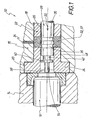
- FIG. 1 shows sections in longitudinal section, to an enlarged scale, not to scale, of an embodiment of the initiating system 10 for a caseless ammunition, of which the powder body 12 is shown in sections.
- the powder body 12 is positioned in a powder cross slide 14.
- a weapon thrust plate 16 Adjacent to the cartridge chamber 14 is a weapon thrust plate 16, which is formed with a through hole 18.
- the through hole 18 is formed on its front side facing the cartridge chamber 14 with a circumferential extension 20.
- a sealing bush 22 is arranged, which has a peripheral collar 24 on the front side.
- the collar 24 is housed in the extension 20 so that the sealing bushing 22 is immovable axially rearward with respect to the weapon buttock 16.
- the sealing bush 22 is formed with a firing pin through hole 26 in which a firing pin 28 is arranged axially adjustable.
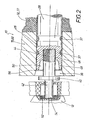
- the firing pin 28 is moved, for example by means of a (not shown) control piece from the initial position shown in Figure 1 in the drawn in Figure 2 end ignition position. This movement is indicated in Figure 1 by the arrow 30.
- the sealing bush 22 disposed in the weapon butt 16 for the firing pin 18 is formed with a grease reservoir 32 connected to a grease source (not shown) by means of a grease channel 34 extending through the gun butt 16.
- the firing pin 28 is formed with at least one circumferential fat groove 36.
- the firing pin 28 is formed with two axially spaced circumferential fat grooves 36.
- the fat grooves 36 are assigned to the fat reservoir 32, so that the fat grooves 36 are filled with fat 37 located in the fat reservoir 32.
- the grease grooves 36 entrain the grease 37 in them, thereby forming a greasy film between the firing pin 28 and the through hole 26 in the sealing bushing 42 is generated, which contributes to gas sealing and to avoid traces of friction.
- the through hole 26 is formed for the firing pin 28 at its front end facing the cartridge chamber 14 with an inlet portion 38 widening towards the chamber 14.
- the inlet section 38 is frustoconically widened with a flat cone angle. Likewise, it is for example possible that the inlet section 38 is formed widened with a gentle radius.
- the firing pin 28 is formed on the front side with a deflector 40, whose operation will be described in more detail below.
- the deflector 40 is formed on a firing pin front part 42.
- the firing pin front part 42 is formed on the rear side with an externally threaded portion 44.
- the firing pin 28 is formed on the front side with a threaded bore 46.
- the firing pin front 42 is screwed with its rear male threaded portion 44 in the threaded bore 46 of the firing pin 28.
- the firing pin 28 is also formed on the front side with a circumferential sealing lip 48, which is determined or limited on the inside by a frustoconical tapering annular surface 50 backwards.
- FIG. 2 also shows an ignition means 52 in which the firing pin 28 with its tip 54 projects into the end position in order to ignite the ignition means 52.
- the operation of the initiating system 10 according to FIGS. 1 and 2 is as follows:
- the firing pin 28 is driven by means of a drive, e.g. is an unillustrated control piece, accelerated in the direction of arrow 30 (see Figure 1), so that the tip 54 of the firing pin 28 is pushed into the powder body 12 and the ignition means 52.
- a drive e.g. is an unillustrated control piece, accelerated in the direction of arrow 30 (see Figure 1), so that the tip 54 of the firing pin 28 is pushed into the powder body 12 and the ignition means 52.
- end ignition position of the firing pin 28 is held until the gas pressure generated by the ignited powder body 12 has degraded. Only then is the firing pin 28 moved back again from the end firing position shown in FIG. 2 into the starting position shown in FIG. During these movements, the firing pin 28 moves with its fat grooves 36 into and through the grease reservoir 32.
- the wall 37 of the through hole 26 is greased with the grease 37 remaining in the grease grooves 36.
- the deflector 40 of the firing pin 28 prevents direct bombardment of the circumferential sealing lip 48 by accelerated powder and / or Zündffenmaschine.
- the circumferential sealing lip 48 comes in the piercing movement of the firing pin 28 just before the transition edge between the cylindrical through hole 18 and the inlet section 38 to a stop.
Landscapes
- Engineering & Computer Science (AREA)
- General Engineering & Computer Science (AREA)
- Air Bags (AREA)
- Aiming, Guidance, Guns With A Light Source, Armor, Camouflage, And Targets (AREA)
- Electrical Discharge Machining, Electrochemical Machining, And Combined Machining (AREA)
- Valve-Gear Or Valve Arrangements (AREA)
- Emergency Lowering Means (AREA)
- Portable Nailing Machines And Staplers (AREA)
Claims (8)
- Système d'amorçage pour munitions sans douille, comprenant un culot de percussion d'arme (16) et un obturateur transversal à poudre (14) contigu du côté frontal au culot de percussion d'arme (16), un percuteur (28) étant disposé dans un orifice de passage (26) du culot de percussion d'arme (16) de façon à pouvoir être déplacé axialement, un corps en poudre (12) amorçable par le percuteur (28) pouvant être disposé avec un artifice de tir (52) dans l'obturateur transversal à poudre (14), le culot de percussion d'arme (16) présentant un réservoir de graisse (32) ouvert en direction de l'orifice de passage (26), et le percuteur (28) étant conformé avec au moins une rainure pour graisse (36) sur sa circonférence, et le percuteur (28) étant conformé sur son côté frontal avec une lèvre d'étanchéité (48) sur sa circonférence, caractérisé en ce que le percuteur (28) présente sur son côté frontal une chicane (40) destinée à empêcher un bombardement direct de la lèvre d'étanchéité (48) circonférentielle par des fractions accélérées de poudre et/ou d'artifice de tir.
- Système d'amorçage selon la revendication 1, caractérisé en ce que le culot de percussion d'arme (16) présente un manchon d'étanchéité (22) qui est conformé avec l'orifice de passage (26) pour le percuteur (28) et avec le réservoir de graisse (32).
- Système d'amorçage selon la revendication 1 ou 2, caractérisé en ce que l'orifice de passage (26) pour le percuteur (28) est conformé sur son extrémité frontale tournée vers l'obturateur transversal à poudre (14) avec un tronçon d'admission (38) s'élargissant en direction de l'obturateur transversal à poudre (14).
- Système d'amorçage selon la revendication 3, caractérisé en ce que le tronçon d'admission (38) est conformé de façon élargie en cône tronqué avec un angle conique plat.
- Système d'amorçage selon la revendication 3, caractérisé en ce que le tronçon d'admission (38) est conformé de façon élargie avec un rayon doux.
- Système d'amorçage selon la revendication 5, caractérisé en ce que la chicane (40) est prévue sur une partie frontale de percuteur (42) qui est raccordée solidairement au percuteur (28).
- Système d'amorçage selon la revendication 6, caractérisé en ce que le percuteur (28) est conformé sur son côté frontal avec un orifice fileté (46) et la partie frontale de percuteur (42) est conformée sur son côté arrière avec un tronçon fileté extérieurement (44) vissé dans l'orifice fileté (46).
- Système d'amorçage selon l'une quelconque des revendications précédentes, caractérisé en ce que la lèvre d'étanchéité circonférentielle (48) présente une surface annulaire (50) se rétrécissant coniquement vers l'arrière.
Applications Claiming Priority (2)
| Application Number | Priority Date | Filing Date | Title |
|---|---|---|---|
| DE102005004936 | 2005-02-03 | ||
| DE102005012284A DE102005012284A1 (de) | 2005-02-03 | 2005-03-17 | Mechanisches Initiiersystem für hülsenlose Munition |
Publications (2)
| Publication Number | Publication Date |
|---|---|
| EP1688694A1 EP1688694A1 (fr) | 2006-08-09 |
| EP1688694B1 true EP1688694B1 (fr) | 2007-08-08 |
Family
ID=36278906
Family Applications (1)
| Application Number | Title | Priority Date | Filing Date |
|---|---|---|---|
| EP06001925A Expired - Lifetime EP1688694B1 (fr) | 2005-02-03 | 2006-01-31 | Système mécanique d'initiation pour munitions sans douille |
Country Status (4)
| Country | Link |
|---|---|
| US (1) | US7357059B2 (fr) |
| EP (1) | EP1688694B1 (fr) |
| AT (1) | ATE369537T1 (fr) |
| DE (2) | DE102005012284A1 (fr) |
Families Citing this family (5)
| Publication number | Priority date | Publication date | Assignee | Title |
|---|---|---|---|---|
| GB2425162B (en) * | 2005-04-12 | 2007-04-11 | Simon Trendall | An improvement to high pressure hydraulic breech mechanisms |
| DE102009024710A1 (de) | 2009-06-12 | 2010-12-23 | Rheinmetall Waffe Munition Gmbh | Hülsenlose Munition |
| DE102010006606A1 (de) * | 2010-02-01 | 2011-08-04 | Diehl BGT Defence GmbH & Co. KG, 88662 | Dichtungsring und Treibladungslager |
| FR3094472B1 (fr) * | 2019-03-29 | 2023-05-26 | Cta Int | Fourreau de soupape pour canon CT40 |
| UA124985C2 (uk) * | 2019-08-20 | 2021-12-22 | Георгій Георгійович Макаров | Безгільзова магазинна зброя (варіанти) |
Family Cites Families (16)
| Publication number | Priority date | Publication date | Assignee | Title |
|---|---|---|---|---|
| DE298815C (fr) | ||||
| US1313912A (en) * | 1919-08-26 | Necticut | ||
| US1345565A (en) * | 1920-03-25 | 1920-07-06 | Thomas F Ryan | Obturating firing-pin |
| CH91600A (de) | 1920-08-12 | 1921-11-01 | Ernst Ludorf | Einrichtung an Gewehren zum Abfeuern von Geschossen. |
| FR595188A (fr) * | 1924-03-17 | 1925-09-28 | Sécurité contre le retour de flammes dans les armes à feu, notamment les canons | |
| US3474560A (en) * | 1968-04-04 | 1969-10-28 | Olin Mathieson | Caseless cartridge chamber-sleeve ejector and binary feed system |
| US3547001A (en) * | 1968-06-13 | 1970-12-15 | Trw Inc | Gun for caseless ammunition in which a slidable sleeve defines the chamber |
| CH509563A (de) | 1969-06-03 | 1971-06-30 | Oerlikon Buehrle Ag | Automatische Feuerwaffe |
| DE2105295C1 (de) | 1971-02-05 | 1977-04-21 | Fa. Diehl, 8500 Nürnberg | Pulverkörper für hülsenlose Munition |
| US3728938A (en) * | 1971-04-16 | 1973-04-24 | A Scibor | Breech seal for caseless ammunition firearm |
| US3872615A (en) * | 1972-03-30 | 1975-03-25 | Andrew J Grandy | Ammunition and weapon systems |
| DE2313591C2 (de) * | 1973-03-19 | 1982-10-07 | Mauser-Werke Oberndorf Gmbh, 7238 Oberndorf | Kurzbauende Handfeuerwaffe mit mehreren achsparallelen Waffenrohren |
| BE824144A (fr) * | 1974-02-07 | 1975-05-02 | Percuteur pour armes a feu a canon portatives | |
| DE2743770C2 (de) * | 1977-09-29 | 1986-11-27 | Rheinmetall GmbH, 4000 Düsseldorf | Vorrichtung zum elektrischen Anzünden einer pyrotechnischen Ladung |
| US4581836A (en) * | 1983-07-25 | 1986-04-15 | Bangor Punta Corporation | Firing pin and firing pin-bushing assembly |
| FR2678057B1 (fr) * | 1991-06-18 | 1995-02-17 | Giat Ind Sa | Dispositif de percussion pour une arme a feu. |
-
2005
- 2005-03-17 DE DE102005012284A patent/DE102005012284A1/de not_active Withdrawn
-
2006
- 2006-01-23 US US11/337,419 patent/US7357059B2/en not_active Expired - Fee Related
- 2006-01-31 AT AT06001925T patent/ATE369537T1/de active
- 2006-01-31 DE DE502006000050T patent/DE502006000050D1/de not_active Expired - Lifetime
- 2006-01-31 EP EP06001925A patent/EP1688694B1/fr not_active Expired - Lifetime
Also Published As
| Publication number | Publication date |
|---|---|
| ATE369537T1 (de) | 2007-08-15 |
| DE502006000050D1 (de) | 2007-09-20 |
| DE102005012284A1 (de) | 2006-08-10 |
| US20060254109A1 (en) | 2006-11-16 |
| US7357059B2 (en) | 2008-04-15 |
| EP1688694A1 (fr) | 2006-08-09 |
Similar Documents
| Publication | Publication Date | Title |
|---|---|---|
| DE69915493T2 (de) | Patrone für selbstladewaffe | |
| DE2914049C2 (de) | Patrone | |
| EP1085289B1 (fr) | Culot de douille de cartouche pour munition de gros calibre | |
| DE69636832T2 (de) | Lauf mit axial hintereinander angeordneten projektilen | |
| DE2022268A1 (de) | Patronenhuelse | |
| DE1728364B1 (de) | Geschoss fuer Schusswaffen | |
| EP0764826A1 (fr) | Projectile porteur supportant un projectile unique secondaire du type pénétrateur | |
| DE102014102672B4 (de) | Feuerwaffe, insbesondere Handfeuerwaffe, sowie Verfahren zur Herstellung einer Feuerwaffe | |
| EP0656522B1 (fr) | Douille pour cartouche | |
| DE3872805T2 (de) | Verbindungsring zwischen geschoss und geschosshuelse. | |
| EP0215829B1 (fr) | Moyen de propulsion pour reduire la trainee de culot d'un engin ballistique | |
| DE69214201T2 (de) | Schlagbolzenanordnung für Feuerwaffe | |
| EP1688694B1 (fr) | Système mécanique d'initiation pour munitions sans douille | |
| DE2324482C3 (de) | Patronenhülse für Schlagzündung | |
| DE3544528C1 (en) | Tandem charge system having integrated protection elements | |
| DE60007943T2 (de) | Verbindungsteil zwischen Geschoss und Geschosshülse und Methode zur Montage eines Dichtringes mittels eines derartigen Verbindungteiles | |
| WO1993018364A1 (fr) | Procede et dispositif pour tirer des munitions sans douilles | |
| EP1013381B1 (fr) | Outil de scellement actionné par poudre | |
| DE2232866A1 (de) | Loesbare verbindung zwischen geschoss und treibladungshuelse | |
| DE19751932C2 (de) | Gasgenerator zur Reichweitensteigerung eines Geschosses und Geschoß mit Gasgenerator | |
| EP0361032B1 (fr) | Allumeur de charge propulsive avec charge de découpage à amorçage par la poudre de la charge propulsive | |
| EP2531800B1 (fr) | Bague d'étanchéité et magasin de charge propulsive | |
| DE602004003544T2 (de) | Zündvorrichtung für mindestens zwei pyrotechnische Zusammensetzungen oder antreibende Ladungen eines Projektiles | |
| EP1617167B1 (fr) | Projectile d'artillerie avec ceinture de guidage | |
| DE3210128A1 (de) | Laufkammer fuer ein geschuetz |
Legal Events
| Date | Code | Title | Description |
|---|---|---|---|
| PUAI | Public reference made under article 153(3) epc to a published international application that has entered the european phase |
Free format text: ORIGINAL CODE: 0009012 |
|
| 17P | Request for examination filed |
Effective date: 20060602 |
|
| AK | Designated contracting states |
Kind code of ref document: A1 Designated state(s): AT BE BG CH CY CZ DE DK EE ES FI FR GB GR HU IE IS IT LI LT LU LV MC NL PL PT RO SE SI SK TR |
|
| AX | Request for extension of the european patent |
Extension state: AL BA HR MK YU |
|
| 17Q | First examination report despatched |
Effective date: 20061016 |
|
| GRAP | Despatch of communication of intention to grant a patent |
Free format text: ORIGINAL CODE: EPIDOSNIGR1 |
|
| AKX | Designation fees paid |
Designated state(s): AT BE CH DE FR LI |
|
| GRAS | Grant fee paid |
Free format text: ORIGINAL CODE: EPIDOSNIGR3 |
|
| GRAA | (expected) grant |
Free format text: ORIGINAL CODE: 0009210 |
|
| AK | Designated contracting states |
Kind code of ref document: B1 Designated state(s): AT BE CH DE FR LI |
|
| REG | Reference to a national code |
Ref country code: CH Ref legal event code: EP |
|
| REF | Corresponds to: |
Ref document number: 502006000050 Country of ref document: DE Date of ref document: 20070920 Kind code of ref document: P |
|
| ET | Fr: translation filed | ||
| PLBE | No opposition filed within time limit |
Free format text: ORIGINAL CODE: 0009261 |
|
| STAA | Information on the status of an ep patent application or granted ep patent |
Free format text: STATUS: NO OPPOSITION FILED WITHIN TIME LIMIT |
|
| 26N | No opposition filed |
Effective date: 20080509 |
|
| PGFP | Annual fee paid to national office [announced via postgrant information from national office to epo] |
Ref country code: FR Payment date: 20120206 Year of fee payment: 7 Ref country code: CH Payment date: 20120123 Year of fee payment: 7 |
|
| PGFP | Annual fee paid to national office [announced via postgrant information from national office to epo] |
Ref country code: BE Payment date: 20120117 Year of fee payment: 7 |
|
| PGFP | Annual fee paid to national office [announced via postgrant information from national office to epo] |
Ref country code: DE Payment date: 20120321 Year of fee payment: 7 |
|
| PGFP | Annual fee paid to national office [announced via postgrant information from national office to epo] |
Ref country code: AT Payment date: 20120111 Year of fee payment: 7 |
|
| BERE | Be: lapsed |
Owner name: DIEHL BGT DEFENCE G.M.B.H. & CO.KG Effective date: 20130131 |
|
| REG | Reference to a national code |
Ref country code: CH Ref legal event code: PL |
|
| REG | Reference to a national code |
Ref country code: AT Ref legal event code: MM01 Ref document number: 369537 Country of ref document: AT Kind code of ref document: T Effective date: 20130131 |
|
| REG | Reference to a national code |
Ref country code: FR Ref legal event code: ST Effective date: 20130930 |
|
| PG25 | Lapsed in a contracting state [announced via postgrant information from national office to epo] |
Ref country code: BE Free format text: LAPSE BECAUSE OF NON-PAYMENT OF DUE FEES Effective date: 20130131 Ref country code: DE Free format text: LAPSE BECAUSE OF NON-PAYMENT OF DUE FEES Effective date: 20130801 Ref country code: AT Free format text: LAPSE BECAUSE OF NON-PAYMENT OF DUE FEES Effective date: 20130131 Ref country code: LI Free format text: LAPSE BECAUSE OF NON-PAYMENT OF DUE FEES Effective date: 20130131 Ref country code: CH Free format text: LAPSE BECAUSE OF NON-PAYMENT OF DUE FEES Effective date: 20130131 |
|
| REG | Reference to a national code |
Ref country code: DE Ref legal event code: R119 Ref document number: 502006000050 Country of ref document: DE Effective date: 20130801 |
|
| PG25 | Lapsed in a contracting state [announced via postgrant information from national office to epo] |
Ref country code: FR Free format text: LAPSE BECAUSE OF NON-PAYMENT OF DUE FEES Effective date: 20130131 |