EP1688694B1 - Mechanical initiating system for caseless ammunition - Google Patents
Mechanical initiating system for caseless ammunition Download PDFInfo
- Publication number
- EP1688694B1 EP1688694B1 EP06001925A EP06001925A EP1688694B1 EP 1688694 B1 EP1688694 B1 EP 1688694B1 EP 06001925 A EP06001925 A EP 06001925A EP 06001925 A EP06001925 A EP 06001925A EP 1688694 B1 EP1688694 B1 EP 1688694B1
- Authority
- EP
- European Patent Office
- Prior art keywords
- firing pin
- initiation system
- powder
- hole
- breech face
- Prior art date
- Legal status (The legal status is an assumption and is not a legal conclusion. Google has not performed a legal analysis and makes no representation as to the accuracy of the status listed.)
- Expired - Lifetime
Links
Images
Classifications
-
- F—MECHANICAL ENGINEERING; LIGHTING; HEATING; WEAPONS; BLASTING
- F41—WEAPONS
- F41A—FUNCTIONAL FEATURES OR DETAILS COMMON TO BOTH SMALLARMS AND ORDNANCE, e.g. CANNONS; MOUNTINGS FOR SMALLARMS OR ORDNANCE
- F41A19/00—Firing or trigger mechanisms; Cocking mechanisms
- F41A19/06—Mechanical firing mechanisms, e.g. counterrecoil firing, recoil actuated firing mechanisms
- F41A19/13—Percussion or firing pins, i.e. fixed or slidably-mounted striker elements; Mountings therefor
-
- F—MECHANICAL ENGINEERING; LIGHTING; HEATING; WEAPONS; BLASTING
- F41—WEAPONS
- F41A—FUNCTIONAL FEATURES OR DETAILS COMMON TO BOTH SMALLARMS AND ORDNANCE, e.g. CANNONS; MOUNTINGS FOR SMALLARMS OR ORDNANCE
- F41A29/00—Cleaning or lubricating arrangements
- F41A29/04—Lubricating, oiling or greasing means, e.g. operating during use
Definitions
- the invention relates to a mechanical initiation system for caseless ammunition according to the preamble of claim 1.
- the firing pin is provided tribladungshunt section with an annular sealing lip.
- This sealing lip leads at gas pressure from the propellant charge chamber by elastic expansion to an intimate contact with the inner wall of the through hole for the firing pin.
- the passage hole for the striker is sealed backward upon ignition of a powder body in the propellant charge chamber.
- the sealing lip is acted upon when igniting the powder body located in the propellant charge chamber directly from the hot, accelerated to high speeds combustion residues and Zündstoff puzzle. This leads after a certain number of ignition processes to a steadily progressing erosion of the sealing lip.
- the invention has for its object to provide an initiating system of the type mentioned, with simple means a reliable sealing of the firing pin is realized in the intended for him through hole.
- the invention has the advantage that in each path position of the firing pin a reliable sealing of the firing pin is ensured against the wall of the provided for him in the weapons shock bottom through hole.
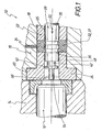
- FIG. 1 shows sections in longitudinal section, to an enlarged scale, not to scale, of an embodiment of the initiating system 10 for a caseless ammunition, of which the powder body 12 is shown in sections.
- the powder body 12 is positioned in a powder cross slide 14.
- a weapon thrust plate 16 Adjacent to the cartridge chamber 14 is a weapon thrust plate 16, which is formed with a through hole 18.
- the through hole 18 is formed on its front side facing the cartridge chamber 14 with a circumferential extension 20.
- a sealing bush 22 is arranged, which has a peripheral collar 24 on the front side.
- the collar 24 is housed in the extension 20 so that the sealing bushing 22 is immovable axially rearward with respect to the weapon buttock 16.
- the sealing bush 22 is formed with a firing pin through hole 26 in which a firing pin 28 is arranged axially adjustable.
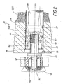
- the firing pin 28 is moved, for example by means of a (not shown) control piece from the initial position shown in Figure 1 in the drawn in Figure 2 end ignition position. This movement is indicated in Figure 1 by the arrow 30.
- the sealing bush 22 disposed in the weapon butt 16 for the firing pin 18 is formed with a grease reservoir 32 connected to a grease source (not shown) by means of a grease channel 34 extending through the gun butt 16.
- the firing pin 28 is formed with at least one circumferential fat groove 36.
- the firing pin 28 is formed with two axially spaced circumferential fat grooves 36.
- the fat grooves 36 are assigned to the fat reservoir 32, so that the fat grooves 36 are filled with fat 37 located in the fat reservoir 32.
- the grease grooves 36 entrain the grease 37 in them, thereby forming a greasy film between the firing pin 28 and the through hole 26 in the sealing bushing 42 is generated, which contributes to gas sealing and to avoid traces of friction.
- the through hole 26 is formed for the firing pin 28 at its front end facing the cartridge chamber 14 with an inlet portion 38 widening towards the chamber 14.
- the inlet section 38 is frustoconically widened with a flat cone angle. Likewise, it is for example possible that the inlet section 38 is formed widened with a gentle radius.
- the firing pin 28 is formed on the front side with a deflector 40, whose operation will be described in more detail below.
- the deflector 40 is formed on a firing pin front part 42.
- the firing pin front part 42 is formed on the rear side with an externally threaded portion 44.
- the firing pin 28 is formed on the front side with a threaded bore 46.
- the firing pin front 42 is screwed with its rear male threaded portion 44 in the threaded bore 46 of the firing pin 28.
- the firing pin 28 is also formed on the front side with a circumferential sealing lip 48, which is determined or limited on the inside by a frustoconical tapering annular surface 50 backwards.
- FIG. 2 also shows an ignition means 52 in which the firing pin 28 with its tip 54 projects into the end position in order to ignite the ignition means 52.
- the operation of the initiating system 10 according to FIGS. 1 and 2 is as follows:
- the firing pin 28 is driven by means of a drive, e.g. is an unillustrated control piece, accelerated in the direction of arrow 30 (see Figure 1), so that the tip 54 of the firing pin 28 is pushed into the powder body 12 and the ignition means 52.
- a drive e.g. is an unillustrated control piece, accelerated in the direction of arrow 30 (see Figure 1), so that the tip 54 of the firing pin 28 is pushed into the powder body 12 and the ignition means 52.
- end ignition position of the firing pin 28 is held until the gas pressure generated by the ignited powder body 12 has degraded. Only then is the firing pin 28 moved back again from the end firing position shown in FIG. 2 into the starting position shown in FIG. During these movements, the firing pin 28 moves with its fat grooves 36 into and through the grease reservoir 32.
- the wall 37 of the through hole 26 is greased with the grease 37 remaining in the grease grooves 36.
- the deflector 40 of the firing pin 28 prevents direct bombardment of the circumferential sealing lip 48 by accelerated powder and / or Zündffenmaschine.
- the circumferential sealing lip 48 comes in the piercing movement of the firing pin 28 just before the transition edge between the cylindrical through hole 18 and the inlet section 38 to a stop.
Landscapes
- Engineering & Computer Science (AREA)
- General Engineering & Computer Science (AREA)
- Air Bags (AREA)
- Aiming, Guidance, Guns With A Light Source, Armor, Camouflage, And Targets (AREA)
- Electrical Discharge Machining, Electrochemical Machining, And Combined Machining (AREA)
- Valve-Gear Or Valve Arrangements (AREA)
- Portable Nailing Machines And Staplers (AREA)
- Emergency Lowering Means (AREA)
Abstract
Description
Die Erfindung betrifft ein mechanisches Initiiersystem für hülsenlose Munition gemäß dem Oberbegriff des Anspruches 1.The invention relates to a mechanical initiation system for caseless ammunition according to the preamble of claim 1.
Aus der
- 1. Die Spitze des Schlagbolzens muss in den Pulverkörper eindringen und durch Schlag bzw. Reibung das Zündmittel initiieren;
- 2. der Schlagbolzen muss das Durchgangsloch, in dem er axial verstellbar ist, nach der Zündung gegen den hohen Gasdruck der heißen Pulvergase abdichten. Zu diesem Zwecke verdeutlicht die oben genannte
DE 21 05 295 C1
- 1. The tip of the firing pin must penetrate into the powder body and initiate the ignition means by impact or friction;
- 2. The firing pin must seal the through hole, in which it is axially adjustable, after ignition against the high gas pressure of the hot powder gases. For this purpose, the above-mentioned
DE 21 05 295 C1
Aus der
Der Erfindung liegt die Aufgabe zugrunde, ein Initiiersystem der eingangs genannten Art zu schaffen, wobei mit einfachen Mitteln eine zuverlässige Abdichtung des Schlagbolzens in dem für ihn vorgesehenen Durchgangsloch realisiert wird.The invention has for its object to provide an initiating system of the type mentioned, with simple means a reliable sealing of the firing pin is realized in the intended for him through hole.
Diese Aufgabe wird bei einem Initiiersystem der eingangs genannten Art erfindungsgemäß durch die Merkmale des Kennzeichenteiles des Anspruches 1 gelöst. Bevorzugte Aus- bzw. Weiterbildungen des erfindungsgemäßen Initiiersystems sind in den Unteransprüchen gekennzeichnetThis object is achieved according to the invention in an initiating system of the type mentioned by the features of the characterizing part of claim 1. Preferred embodiments or further developments of the initiator system according to the invention are characterized in the subclaims
Die Erfindung weist den Vorteil auf, dass in jeder Weg-Position des Schlagbolzens eine zuverlässige Abdichtung des Schlagbolzens gegen die Wandung des für ihn im Waffen-Stoßboden vorgesehenen Durchgangsloches gewährleistet ist.The invention has the advantage that in each path position of the firing pin a reliable sealing of the firing pin is ensured against the wall of the provided for him in the weapons shock bottom through hole.
Weitere Einzelheiten, Merkmale und Vorteile ergeben sich aus der nachfolgenden Beschreibung eines in der Zeichnung abschnittweise und teilweise aufgeschnitten, nicht maßstabgetreu gezeichneten Ausführungsbeispieles des erfindungsgemäßen Initiiersystems in zwei unterschiedlichen Betriebszuständen.Further details, features and advantages will become apparent from the following description of a portion of the drawing and partially cut away, not drawn to scale exemplary embodiment of the initiation system according to the invention in two different operating conditions.
- Figur 1 das Initiiersystem in der Ausgangsstellung des Schlagbolzens, undFigure 1 shows the initiation system in the initial position of the firing pin, and
- Figur 2 das Initiiersystem in der End-Zündstellung des Schlagbolzens.Figure 2 shows the initiation system in the final ignition position of the firing pin.
Figur 1 zeigt abschnittweise längsgeschnitten in einem vergrößerten Maßstab, nicht maßstabgetreu, eine Ausbildung des Initiiersystems 10 für eine hülsenlose Munition, von der der Pulverkörper 12 abschnittweise gezeichnet ist. Der Pulverkörper 12 ist in einem Pulver-Querschieber 14 positioniert. An das Patronenlager 14 grenzt ein Waffen-Stoßboden 16 an, der mit einem Durchgangsloch 18 ausgebildet ist. Das Durchgangsloch 18 ist an seiner dem Patronenlager 14 zugewandten Vorderseite mit einer umlaufenden Erweiterung 20 ausgebildet. Im Durchgangsloch 18 des Waffen-Stoßbodens 16 ist eine Dichtungsbuchse 22 angeordnet, die vorderseitig einen umlaufenden Bund 24 aufweist. Der Bund 24 ist in der Erweiterung 20 untergebracht, so dass die Dichtungsbuchse 22 in Bezug zum Waffen-Stoßboden 16 axial nach hinten unbeweglich ist.FIG. 1 shows sections in longitudinal section, to an enlarged scale, not to scale, of an embodiment of the initiating
Die Dichtungsbuchse 22 ist mit einem Schlagbolzen-Durchgangsloch 26 ausgebildet, in dem ein Schlagbolzen 28 axial verstellbar angeordnet ist. Der Schlagbolzen 28 wird beispielsweise mittels eines (nicht gezeichneten) Steuerstückes von der in Figur 1 gezeichneten Ausgangsstellung in die in Figur 2 gezeichnete End-Zündstellung bewegt. Diese Bewegung ist in Figur 1 durch den Pfeil 30 angedeutet.The sealing
Die im Waffen-Stoßboden 16 für den Schlagbolzen 18 angeordnete Dichtungsbuchse 22 ist mit einem Fettreservoir 32 ausgebildet, das mittels eines Fettkanals 34, der sich durch den Waffen-Stoßboden 16 erstreckt, mit einer (nicht dargestellten) Fettquelle verbunden ist.The sealing
Der Schlagbolzen 28 ist mit mindestens einer umlaufenden Fettrille 36 ausgebildet. Bei der Ausbildung gemäß Figur 1 ist der Schlagbolzen 28 mit zwei axial voneinander beabstandeten umlaufenden Fettrillen 36 ausgebildet.The
In der in Figur 1 gezeichneten Ausgangsstellung des Schlagbolzen 28 sind die Fettrillen 36 dem Fettreservoir 32 zugeordnet, so dass die Fettrillen 36 mit im Fettreservoir 32 befindlichem Fett 37 gefüllt werden.In the initial position of the
Wird der Schlagbolzen 28 von der in Figur 1 gezeichneten Ausgangsstellung in die in Figur 2 gezeichnete End-Zündstellung beschleunigt, so nehmen die Fettrillen 36 das in ihnen befindliche Fett 37 mit, wodurch zwischen dem Schlagbolzen 28 und dem Durchgangsloch 26 in der Dichtungsbuchse 42 ein Fettfilm erzeugt wird, der zur Gasabdichtung und zur Vermeidung von Reibspuren beiträgt.If the
Wie aus den Figuren 1 und 2, in welchen gleiche Einzelheiten jeweils mit denselben Bezugsziffern bezeichnet sind, ersichtlich ist, ist das Durchgangsloch 26 für den Schlagbolzen 28 an seinem dem Patronenlager 14 zugewandten Vorderende mit einem sich zum Patronenlager 14 hin erweiternden Einlaufabschnitt 38 ausgebildet. Der Einlaufabschnitt 38 ist mit einem flachen Konuswinkel kegelstumpfförmig erweitert gestaltet. Desgleichen ist es bspw. möglich, dass der Einlaufabschnitt 38 mit einem sanften Radius erweitert ausgebildet ist.As can be seen from Figures 1 and 2, in which the same details are denoted by the same reference numerals, the
Der Schlagbolzen 28 ist vorderseitig mit einem Abweiser 40 ausgebildet, dessen Funktionsweise weiter unten noch ausführlicher beschrieben wird. Wie aus Figur 2 ersichtlich ist, ist der Abweiser 40 an einem Schlagbolzen-Vorderteil 42 ausgebildet. Das Schlagbolzen-Vorderteil 42 ist rückseitig mit einem Außengewindeabschnitt 44 ausgebildet. Der Schlagbolzen 28 ist vorderseitig mit einer Gewindebohrung 46 ausgebildet. Das Schlagbolzen-Vorderteil 42 ist mit seinem rückseitigen Außengewindeabschnitt 44 in die Gewindebohrung 46 des Schlagbolzens 28 eingeschraubt.The
Der Schlagbolzen 28 ist vorderseitig außerdem mit einer umlaufenden Dichtungslippe 48 ausgebildet, die innenseitig durch eine sich nach rückwärts kegelstumpfförmig verjüngende Ringfläche 50 bestimmt bzw. begrenzt ist.The
In Figur 2 ist außerdem ein Zündmittel 52 dargestellt, in das der Schlagbolzen 28 mit seiner Spitze 54 in der Endstellung hineinsteht, um das Zündmittel 52 zu zünden.FIG. 2 also shows an ignition means 52 in which the
Die Funktionsweise des Initiiersystems 10 gemäß den Figuren 1 und 2 ist wie folgt:The operation of the initiating
Der Schlagbolzen 28 wird mittels eines Antriebes, bei dem es sich z.B. um ein nicht dargestelltes Steuerstück handelt, in Richtung des Pfeiles 30 (siehe Figur 1) beschleunigt, so dass die Spitze 54 des Schlagbolzens 28 in den Pulverkörper 12 und in das Zündmittel 52 gestoßen wird. In der in Figur 2 gezeichneten End-Zündstellung wird der Schlagbolzen 28 solange festgehalten, bis sich der vom angezündeten Pulverkörper 12 erzeugte Gasdruck abgebaut hat. Erst danach wird der Schlagbolzen 28 wieder von der in Figur 2 gezeichneten End-Zündstellung in die in Figur 1 dargestellte Ausgangsstellung zurückbewegt. Bei diesen Bewegungen fährt der Schlagbolzen 28 mit seinen Fettrillen 36 in und durch das Fettreservoir 32. Mit dem in den Fettrillen 36 haften bleibendem Fett 37 wird die Wandung des Durchgangsloches 26 gefettet.The
In der in Figur 2 gezeichneten End-Zündstellung des Schlagbolzens 28 wird die vorderseitig um den Schlagbolzen 28 umlaufende Dichtungslippe 48 durch den vom angezündeten Pulverkörper 12 generierten Gasdruck aufgeweitet, so dass die Innenwandung des Durchgangsloches 26 nach rückwärts formschlüssig abgedichtet wird.In the illustrated in Figure 2 end ignition position of the
Der Abweiser 40 des Schlagbolzens 28 verhindert einen direkten Beschuss der umlaufenden Dichtungslippe 48 durch beschleunigte Pulver- und/oder Zündmittelteile.The
Durch den mit einem flachen Konuswinkel kegelstumpfförmig erweiterten Einlaufabschnitt 38 am Vorderende des Durchgangsloches 26 in der Dichtungsbuchse 22 wird ein Verkrusten bzw. Erodieren der dem Schlagbolzen 28 direkt vorgelagerten Übergangskante 56, wie es sich bei einer scharfen d.h. 90°-Kante einstellen würde, verhindert.Due to the frustoconical widened with a shallow cone
Die umlaufende Dichtungslippe 48 kommt in der Anstechbewegung des Schlagbolzens 28 knapp vor der Übergangskante zwischen dem zylindrischen Durchgangsloch 18 und dem Einlaufabschnitt 38 zum Stehen.The
- 1010
- Initiierungssysteminitiation system
- 1212
- Pulverkörper (von 10)Powder body (from 10)
- 1414
- Pulver-Querschieber (von 10)Powder cross slide (from 10)
- 1616
- Waffen-Stoßboden (von 10)Weapon Shock (from 10)
- 1818
- Durchgangsloch (in 16 für 22)Through hole (in 16 for 22)
- 2020
- Erweiterung (von 18 für 24)Extension (from 18 to 24)
- 2222
- Dichtungsbuchse (in 18 für 28)Sealing bush (in 18 for 28)
- 2424
- Bund (von 22)Federation (out of 22)
- 2626
- Schlagbolzen-Durchgangsloch (in 22 für 28)Firing pin through hole (in 22 for 28)
- 2828
- Schlagbolzen (in 26)Firing pin (in 26)
- 3030
- Pfeil / Bewegung (von 28)Arrow / movement (from 28)
- 3232
- Fettreservoir (in 22)Fat reservoir (in 22)
- 3434
- Fettkanal (zu 32)Grease channel (to 32)
- 3636
- Fettrille (in 28)Fettrille (in 28)
- 3737
- Fett (von 32 in 36)Fat (from 32 to 36)
- 3838
- Einlaufabschnitt (von 26)Inlet section (of 26)
- 4040
- Abweiser (von 28)Deflector (from 28)
- 4242
- Schlagbolzen-Vorderteil (von 28)Striker front part (from 28)
- 4444
- Außengewindeabschnitt (von 42)Male threaded section (from 42)
- 4646
- Gewindebohrung (in 28)Threaded hole (in 28)
- 4848
- umlaufende Dichtungsrippe (von 28)circumferential sealing rib (from 28)
- 5050
- Ringfläche (von 48)Ring area (from 48)
- 5252
- Zündmittel (für 12)Ignition (for 12)
- 5454
- Spitze (von 28)Top (from 28)
- 5656
- Übergangskante (von 26)Transition edge (from 26)
Claims (8)
- Mechanical initiation system for caseless ammunition, having a weapon breech face (16) and a powder transverse slide (14) which is adjacent to the weapon breech face (16) at the front end, with a firing pin (28) being arranged such that it can be moved axially in an aperture hole (26) in the weapon breech face (16), in which case a powder body (12) which can be initiated by the firing pin (28) can be arranged with a detonating means (52) in the powder transverse slide (14), with the weapon breech face (16) having a grease reservoir (32) which is open towards the aperture hole (26), and with the firing pin (28) being formed circumferentially with at least one grease groove (36), and with the firing pin (28) being formed with a circumferential sealing lip (48) at the front end,
characterized
in that the firing pin (28) has a guard (40) at the front end in order to prevent accelerated powder and/or detonation means parts directly bombarding the circumferential sealing lip (48). - Initiation system according to Claim 1,
characterized
in that the weapon breech face (16) has a sealing bush (22), which is formed with the aperture hole (26) for the firing pin (28) and with the grease reservoir (32). - Initiation system according to Claim 1 or 2,
characterized
in that the aperture hole (26) for the firing pin (28) is formed with an insertion section (38), which widens towards the powder transverse slide (14), at its front end facing the powder transverse slide (14). - Initiation system according to Claim 3,
characterized
in that the insertion section (38) is designed to widen in a truncated conical shape, with a flat cone angle. - Initiation system according to Claim 3,
characterized
in that the insertion section (38) is designed to widen with a smooth radius. - Initiation system according to Claim 5,
characterized
in that the guard (40) is provided on a firing pin front part (42) which is firmly connected to the firing pin (28). - Initiation system according to Claim 6,
characterized
in that the firing pin (28) has a threaded hole (46) at the front end, and the firing pin front part (42) has an external-threaded section (44), which is screwed into the threaded hole (46), at the rear end. - Initiation system according to one of the preceding claims,
characterized
in that the circumferential sealing lip (48) has an annular surface (50) which tapers conically rearwards.
Applications Claiming Priority (2)
| Application Number | Priority Date | Filing Date | Title |
|---|---|---|---|
| DE102005004936 | 2005-02-03 | ||
| DE102005012284A DE102005012284A1 (en) | 2005-02-03 | 2005-03-17 | Mechanical initiation system for caseless ammunition |
Publications (2)
| Publication Number | Publication Date |
|---|---|
| EP1688694A1 EP1688694A1 (en) | 2006-08-09 |
| EP1688694B1 true EP1688694B1 (en) | 2007-08-08 |
Family
ID=36278906
Family Applications (1)
| Application Number | Title | Priority Date | Filing Date |
|---|---|---|---|
| EP06001925A Expired - Lifetime EP1688694B1 (en) | 2005-02-03 | 2006-01-31 | Mechanical initiating system for caseless ammunition |
Country Status (4)
| Country | Link |
|---|---|
| US (1) | US7357059B2 (en) |
| EP (1) | EP1688694B1 (en) |
| AT (1) | ATE369537T1 (en) |
| DE (2) | DE102005012284A1 (en) |
Families Citing this family (5)
| Publication number | Priority date | Publication date | Assignee | Title |
|---|---|---|---|---|
| GB2425162B (en) * | 2005-04-12 | 2007-04-11 | Simon Trendall | An improvement to high pressure hydraulic breech mechanisms |
| DE102009024710A1 (en) | 2009-06-12 | 2010-12-23 | Rheinmetall Waffe Munition Gmbh | Shellless ammunition |
| DE102010006606A1 (en) * | 2010-02-01 | 2011-08-04 | Diehl BGT Defence GmbH & Co. KG, 88662 | Sealing ring and propellant bearing |
| FR3094472B1 (en) * | 2019-03-29 | 2023-05-26 | Cta Int | Valve sleeve for CT40 cannon |
| UA124985C2 (en) * | 2019-08-20 | 2021-12-22 | Георгій Георгійович Макаров | SHIRT-FREE STORE WEAPONS (OPTIONS) |
Family Cites Families (16)
| Publication number | Priority date | Publication date | Assignee | Title |
|---|---|---|---|---|
| US1313912A (en) * | 1919-08-26 | Necticut | ||
| DE298815C (en) | ||||
| US1345565A (en) * | 1920-03-25 | 1920-07-06 | Thomas F Ryan | Obturating firing-pin |
| CH91600A (en) | 1920-08-12 | 1921-11-01 | Ernst Ludorf | Equipment on rifles for firing projectiles. |
| FR595188A (en) * | 1924-03-17 | 1925-09-28 | Safety against backfire in firearms, especially cannons | |
| US3474560A (en) * | 1968-04-04 | 1969-10-28 | Olin Mathieson | Caseless cartridge chamber-sleeve ejector and binary feed system |
| US3547001A (en) * | 1968-06-13 | 1970-12-15 | Trw Inc | Gun for caseless ammunition in which a slidable sleeve defines the chamber |
| CH509563A (en) | 1969-06-03 | 1971-06-30 | Oerlikon Buehrle Ag | Automatic firearm |
| DE2105295C1 (en) | 1971-02-05 | 1977-04-21 | Fa. Diehl, 8500 Nürnberg | Powder body for caseless ammunition |
| US3728938A (en) * | 1971-04-16 | 1973-04-24 | A Scibor | Breech seal for caseless ammunition firearm |
| US3872615A (en) * | 1972-03-30 | 1975-03-25 | Andrew J Grandy | Ammunition and weapon systems |
| DE2313591C2 (en) * | 1973-03-19 | 1982-10-07 | Mauser-Werke Oberndorf Gmbh, 7238 Oberndorf | Short handgun with several axially parallel gun barrels |
| BE824144A (en) * | 1974-02-07 | 1975-05-02 | PUNCHER FOR PORTABLE CANNON FIREARMS | |
| DE2743770C2 (en) * | 1977-09-29 | 1986-11-27 | Rheinmetall GmbH, 4000 Düsseldorf | Device for the electrical ignition of a pyrotechnic charge |
| US4581836A (en) * | 1983-07-25 | 1986-04-15 | Bangor Punta Corporation | Firing pin and firing pin-bushing assembly |
| FR2678057B1 (en) * | 1991-06-18 | 1995-02-17 | Giat Ind Sa | PERCUSSION DEVICE FOR A FIREARMS. |
-
2005
- 2005-03-17 DE DE102005012284A patent/DE102005012284A1/en not_active Withdrawn
-
2006
- 2006-01-23 US US11/337,419 patent/US7357059B2/en not_active Expired - Fee Related
- 2006-01-31 EP EP06001925A patent/EP1688694B1/en not_active Expired - Lifetime
- 2006-01-31 DE DE502006000050T patent/DE502006000050D1/en not_active Expired - Lifetime
- 2006-01-31 AT AT06001925T patent/ATE369537T1/en active
Also Published As
| Publication number | Publication date |
|---|---|
| ATE369537T1 (en) | 2007-08-15 |
| DE502006000050D1 (en) | 2007-09-20 |
| US20060254109A1 (en) | 2006-11-16 |
| EP1688694A1 (en) | 2006-08-09 |
| DE102005012284A1 (en) | 2006-08-10 |
| US7357059B2 (en) | 2008-04-15 |
Similar Documents
| Publication | Publication Date | Title |
|---|---|---|
| DE69915493T2 (en) | CARTRIDGES FOR SELF-LOADING ARMS | |
| DE2914049C2 (en) | cartridge | |
| EP1085289B1 (en) | Cartridge case base for big calibre ammuniton | |
| DE69636832T2 (en) | RUN WITH AXIAL REAR ORGANIZED PROJECTULES | |
| DE2022268A1 (en) | Cartridge case | |
| DE1728364B1 (en) | Bullet for firearms | |
| EP0764826A1 (en) | Carrier projectile with a single penetrator as the submunition | |
| DE102014102672B4 (en) | Firearm, in particular handgun, and method of making a firearm | |
| EP0656522B1 (en) | Cartridge case | |
| DE3872805T2 (en) | CONNECTION RING BETWEEN BULLET AND BULLET SLEEVE. | |
| EP0215829B1 (en) | Propulsion means for reducing the base drag | |
| DE69214201T2 (en) | Firing pin arrangement for firearm | |
| DE2324482C3 (en) | Cartridge case for impact ignition | |
| EP1688694A1 (en) | Mechanical initiating system for caseless ammunition | |
| DE3544528C1 (en) | Tandem charge system having integrated protection elements | |
| DE19751932C2 (en) | Gas generator for increasing the range of a storey and storey with a gas generator | |
| DE60007943T2 (en) | Connecting part between the projectile and the projectile sleeve and method for assembling a sealing ring by means of such a connecting part | |
| WO1993018364A1 (en) | Process and device for firing caseless ammunition | |
| EP1013381B1 (en) | Powder-actuated fastener driving tool | |
| DE2232866A1 (en) | DETACHABLE CONNECTION BETWEEN FLOOR AND DRIVING LOAD SLEEVE | |
| EP0361032B1 (en) | Propellant charge igniter with a cutting charge ignited by the propellant charge powder | |
| EP2531800B1 (en) | Sealing ring and propellant charge magazine | |
| DE602004003544T2 (en) | Ignition device for at least two pyrotechnic compositions or driving charges of a projectile | |
| EP1617167B1 (en) | Artillery projectile with driving band | |
| DE3210128A1 (en) | RUN CHAMBER FOR A GUN |
Legal Events
| Date | Code | Title | Description |
|---|---|---|---|
| PUAI | Public reference made under article 153(3) epc to a published international application that has entered the european phase |
Free format text: ORIGINAL CODE: 0009012 |
|
| 17P | Request for examination filed |
Effective date: 20060602 |
|
| AK | Designated contracting states |
Kind code of ref document: A1 Designated state(s): AT BE BG CH CY CZ DE DK EE ES FI FR GB GR HU IE IS IT LI LT LU LV MC NL PL PT RO SE SI SK TR |
|
| AX | Request for extension of the european patent |
Extension state: AL BA HR MK YU |
|
| 17Q | First examination report despatched |
Effective date: 20061016 |
|
| GRAP | Despatch of communication of intention to grant a patent |
Free format text: ORIGINAL CODE: EPIDOSNIGR1 |
|
| AKX | Designation fees paid |
Designated state(s): AT BE CH DE FR LI |
|
| GRAS | Grant fee paid |
Free format text: ORIGINAL CODE: EPIDOSNIGR3 |
|
| GRAA | (expected) grant |
Free format text: ORIGINAL CODE: 0009210 |
|
| AK | Designated contracting states |
Kind code of ref document: B1 Designated state(s): AT BE CH DE FR LI |
|
| REG | Reference to a national code |
Ref country code: CH Ref legal event code: EP |
|
| REF | Corresponds to: |
Ref document number: 502006000050 Country of ref document: DE Date of ref document: 20070920 Kind code of ref document: P |
|
| ET | Fr: translation filed | ||
| PLBE | No opposition filed within time limit |
Free format text: ORIGINAL CODE: 0009261 |
|
| STAA | Information on the status of an ep patent application or granted ep patent |
Free format text: STATUS: NO OPPOSITION FILED WITHIN TIME LIMIT |
|
| 26N | No opposition filed |
Effective date: 20080509 |
|
| PGFP | Annual fee paid to national office [announced via postgrant information from national office to epo] |
Ref country code: FR Payment date: 20120206 Year of fee payment: 7 Ref country code: CH Payment date: 20120123 Year of fee payment: 7 |
|
| PGFP | Annual fee paid to national office [announced via postgrant information from national office to epo] |
Ref country code: BE Payment date: 20120117 Year of fee payment: 7 |
|
| PGFP | Annual fee paid to national office [announced via postgrant information from national office to epo] |
Ref country code: DE Payment date: 20120321 Year of fee payment: 7 |
|
| PGFP | Annual fee paid to national office [announced via postgrant information from national office to epo] |
Ref country code: AT Payment date: 20120111 Year of fee payment: 7 |
|
| BERE | Be: lapsed |
Owner name: DIEHL BGT DEFENCE G.M.B.H. & CO.KG Effective date: 20130131 |
|
| REG | Reference to a national code |
Ref country code: CH Ref legal event code: PL |
|
| REG | Reference to a national code |
Ref country code: AT Ref legal event code: MM01 Ref document number: 369537 Country of ref document: AT Kind code of ref document: T Effective date: 20130131 |
|
| REG | Reference to a national code |
Ref country code: FR Ref legal event code: ST Effective date: 20130930 |
|
| PG25 | Lapsed in a contracting state [announced via postgrant information from national office to epo] |
Ref country code: BE Free format text: LAPSE BECAUSE OF NON-PAYMENT OF DUE FEES Effective date: 20130131 Ref country code: DE Free format text: LAPSE BECAUSE OF NON-PAYMENT OF DUE FEES Effective date: 20130801 Ref country code: AT Free format text: LAPSE BECAUSE OF NON-PAYMENT OF DUE FEES Effective date: 20130131 Ref country code: LI Free format text: LAPSE BECAUSE OF NON-PAYMENT OF DUE FEES Effective date: 20130131 Ref country code: CH Free format text: LAPSE BECAUSE OF NON-PAYMENT OF DUE FEES Effective date: 20130131 |
|
| REG | Reference to a national code |
Ref country code: DE Ref legal event code: R119 Ref document number: 502006000050 Country of ref document: DE Effective date: 20130801 |
|
| PG25 | Lapsed in a contracting state [announced via postgrant information from national office to epo] |
Ref country code: FR Free format text: LAPSE BECAUSE OF NON-PAYMENT OF DUE FEES Effective date: 20130131 |