EP1688674A1 - Conditionneur d'air - Google Patents
Conditionneur d'air Download PDFInfo
- Publication number
- EP1688674A1 EP1688674A1 EP04792212A EP04792212A EP1688674A1 EP 1688674 A1 EP1688674 A1 EP 1688674A1 EP 04792212 A EP04792212 A EP 04792212A EP 04792212 A EP04792212 A EP 04792212A EP 1688674 A1 EP1688674 A1 EP 1688674A1
- Authority
- EP
- European Patent Office
- Prior art keywords
- air
- heat exchanger
- adsorption
- room
- adsorption heat
- Prior art date
- Legal status (The legal status is an assumption and is not a legal conclusion. Google has not performed a legal analysis and makes no representation as to the accuracy of the status listed.)
- Withdrawn
Links
Images


Classifications
-
- F—MECHANICAL ENGINEERING; LIGHTING; HEATING; WEAPONS; BLASTING
- F24—HEATING; RANGES; VENTILATING
- F24F—AIR-CONDITIONING; AIR-HUMIDIFICATION; VENTILATION; USE OF AIR CURRENTS FOR SCREENING
- F24F3/00—Air-conditioning systems in which conditioned primary air is supplied from one or more central stations to distributing units in the rooms or spaces where it may receive secondary treatment; Apparatus specially designed for such systems
- F24F3/12—Air-conditioning systems in which conditioned primary air is supplied from one or more central stations to distributing units in the rooms or spaces where it may receive secondary treatment; Apparatus specially designed for such systems characterised by the treatment of the air otherwise than by heating and cooling
- F24F3/14—Air-conditioning systems in which conditioned primary air is supplied from one or more central stations to distributing units in the rooms or spaces where it may receive secondary treatment; Apparatus specially designed for such systems characterised by the treatment of the air otherwise than by heating and cooling by humidification; by dehumidification
-
- B—PERFORMING OPERATIONS; TRANSPORTING
- B01—PHYSICAL OR CHEMICAL PROCESSES OR APPARATUS IN GENERAL
- B01D—SEPARATION
- B01D53/00—Separation of gases or vapours; Recovering vapours of volatile solvents from gases; Chemical or biological purification of waste gases, e.g. engine exhaust gases, smoke, fumes, flue gases, aerosols
- B01D53/26—Drying gases or vapours
- B01D53/263—Drying gases or vapours by absorption
-
- B—PERFORMING OPERATIONS; TRANSPORTING
- B01—PHYSICAL OR CHEMICAL PROCESSES OR APPARATUS IN GENERAL
- B01D—SEPARATION
- B01D53/00—Separation of gases or vapours; Recovering vapours of volatile solvents from gases; Chemical or biological purification of waste gases, e.g. engine exhaust gases, smoke, fumes, flue gases, aerosols
- B01D53/26—Drying gases or vapours
-
- F—MECHANICAL ENGINEERING; LIGHTING; HEATING; WEAPONS; BLASTING
- F24—HEATING; RANGES; VENTILATING
- F24F—AIR-CONDITIONING; AIR-HUMIDIFICATION; VENTILATION; USE OF AIR CURRENTS FOR SCREENING
- F24F3/00—Air-conditioning systems in which conditioned primary air is supplied from one or more central stations to distributing units in the rooms or spaces where it may receive secondary treatment; Apparatus specially designed for such systems
- F24F3/12—Air-conditioning systems in which conditioned primary air is supplied from one or more central stations to distributing units in the rooms or spaces where it may receive secondary treatment; Apparatus specially designed for such systems characterised by the treatment of the air otherwise than by heating and cooling
- F24F3/14—Air-conditioning systems in which conditioned primary air is supplied from one or more central stations to distributing units in the rooms or spaces where it may receive secondary treatment; Apparatus specially designed for such systems characterised by the treatment of the air otherwise than by heating and cooling by humidification; by dehumidification
- F24F3/1411—Air-conditioning systems in which conditioned primary air is supplied from one or more central stations to distributing units in the rooms or spaces where it may receive secondary treatment; Apparatus specially designed for such systems characterised by the treatment of the air otherwise than by heating and cooling by humidification; by dehumidification by absorbing or adsorbing water, e.g. using an hygroscopic desiccant
- F24F3/1429—Air-conditioning systems in which conditioned primary air is supplied from one or more central stations to distributing units in the rooms or spaces where it may receive secondary treatment; Apparatus specially designed for such systems characterised by the treatment of the air otherwise than by heating and cooling by humidification; by dehumidification by absorbing or adsorbing water, e.g. using an hygroscopic desiccant alternatively operating a heat exchanger in an absorbing/adsorbing mode and a heat exchanger in a regeneration mode
-
- F—MECHANICAL ENGINEERING; LIGHTING; HEATING; WEAPONS; BLASTING
- F25—REFRIGERATION OR COOLING; COMBINED HEATING AND REFRIGERATION SYSTEMS; HEAT PUMP SYSTEMS; MANUFACTURE OR STORAGE OF ICE; LIQUEFACTION SOLIDIFICATION OF GASES
- F25B—REFRIGERATION MACHINES, PLANTS OR SYSTEMS; COMBINED HEATING AND REFRIGERATION SYSTEMS; HEAT PUMP SYSTEMS
- F25B13/00—Compression machines, plants or systems, with reversible cycle
-
- F—MECHANICAL ENGINEERING; LIGHTING; HEATING; WEAPONS; BLASTING
- F25—REFRIGERATION OR COOLING; COMBINED HEATING AND REFRIGERATION SYSTEMS; HEAT PUMP SYSTEMS; MANUFACTURE OR STORAGE OF ICE; LIQUEFACTION SOLIDIFICATION OF GASES
- F25B—REFRIGERATION MACHINES, PLANTS OR SYSTEMS; COMBINED HEATING AND REFRIGERATION SYSTEMS; HEAT PUMP SYSTEMS
- F25B2313/00—Compression machines, plants or systems with reversible cycle not otherwise provided for
- F25B2313/023—Compression machines, plants or systems with reversible cycle not otherwise provided for using multiple indoor units
- F25B2313/0234—Compression machines, plants or systems with reversible cycle not otherwise provided for using multiple indoor units in series arrangements
- F25B2313/02343—Compression machines, plants or systems with reversible cycle not otherwise provided for using multiple indoor units in series arrangements during dehumidification
Definitions
- This invention relates to air conditioning apparatus, and in particular, to air conditioning apparatus which are adapted to separately perform room-air sensible heat processing and room-air latent heat processing.
- Air conditioning apparatus air conditioning systems of the type capable of separately performing room-air sensible heat processing and room-air latent heat processing have been known in the conventional art.
- an air conditioning apparatus which mainly performs air sensible heat processing by a vapor compression refrigeration cycle and which performs air latent heat processing with an adsorbent capable of adsorption/desorption of moisture in the air (see for example JP, H09-318126, A).
- This air conditioning system includes an air conditioner which performs sensible heat processing by circulating air in an indoor space, and a desiccant type outdoor air makeup unit which performs latent heat processing by controlling the humidity of outside air and then supplying the humidity-controlled outside air to the indoor space.
- the air conditioner and the desiccant type outdoor air makeup unit are installed independently. This requires a large installation space and the cost is likely to increase as well. On the contrary, even if the air conditioner and the desiccant type outdoor air makeup unit are housed integrally within a single casing so that they may be installed in one location, this also produces problems. That is, the apparatus grows in size. Additionally, the configuration tends to become complicated.
- the desiccant type outdoor air makeup unit requires provision of a heating means for adsorbent regeneration, and the system of the aforesaid gazette employs a heat pump unit as a heating means. And in a conventional configuration, it is required that the vapor compression refrigeration cycle of the air conditioner and the heat pump unit of the desiccant type outdoor air makeup unit be activated independently. There is a possibility of the COP (coefficient of performance) drop.
- an object of the present invention is to prevent air conditioning apparatus which are adapted to separately perform air sensible heat processing and air latent heat processing from growing in size, and to make it possible to perform operations at high COP.
- the present invention provides an air conditioning apparatus which includes a plurality of heat exchangers (11, 12, 13, 14) for effecting heat exchange between a heating medium (refrigerant, cold water, hot water et cetera) and air.
- a heating medium refrigerant, cold water, hot water et cetera
- at least one heat exchanger (13,14) is made up of an adsorption heat exchanger (13, 14) with an adsorbent supported on its surface.
- a first invention is directed to an air conditioning apparatus which is provided with a heating medium circuit (20, 40) for the flow of heating medium and which includes in the heating medium circuit (20, 40) a plurality of heat exchangers (11, 12, 13, 14) for effecting heat exchange between a heating medium and an airstream. And in the air conditioning apparatus of the first invention, at least one heat exchanger (13, 14) is made up of an adsorption heat exchanger (13, 14) with an adsorbent supported on a surface thereof.
- At least one adsorption heat exchanger (13,14) of the heat exchangers (11, 12, 13, 14) performs room-air latent heat processing, while another heat exchanger (13, 14) performs sensible heat processing.
- the adsorption heat exchanger (13, 14) serves as an evaporator of the refrigerant circuit (20) or as a cooler of the cold and hot water circuit (40), it is possible to dehumidify air by adsorbing moisture in the air while cooling the adsorbent.
- the adsorption heat exchanger (13,14) serves as a condenser of the refrigerant circuit (20) or as a heater of the cold and hot water circuit (40), it is possible to humidify air by releasing moisture to the air while heating the adsorbent. During the air humidification, the adsorbent is regenerated.
- any dedicated device for adsorbent regeneration other than the heating medium circuit (20, 40) is no longer required, thereby making it possible to perform high-efficiency operations.
- a second invention provides an air conditioning apparatus according to the air conditioning apparatus of the first invention which is characterized in that the heating medium circuit (20, 40) includes at least two air heat exchangers (11, 12) which mainly perform air sensible heat processing and a single adsorption heat exchanger (13) which mainly performs air latent heat processing.
- the adsorption heat exchanger (13) performs room-air latent heat processing, while at least one air heat exchanger, i.e., the air heat exchanger (11), performs room-air sensible heat processing.
- the air heat exchanger (11) performs room-air sensible heat processing.
- adsorption heat exchanger (13) adsorption of moisture in room air by the adsorbent and adsorbent regeneration are performed alternately, while in the air heat exchangers (11, 12) room-air cooling or heating is continuously performed.
- this invention it becomes possible to intermittently provide dehumidification during the cooling operating mode or to intermittently provide humidification during the heating operating mode.
- a third invention provides an air conditioning apparatus according to the air conditioning apparatus of the first invention which is characterized in that the heating medium circuit (20, 40) includes a single air heat exchanger (11) which mainly performs air sensible heat processing and at least two adsorption heat exchangers (13, 14) which mainly perform air latent heat processing.
- one of the two adsorption heat exchangers (13, 14) is made to serve as an evaporator (or a cooler) while the other adsorption heat exchanger is made to serve as a condenser (or a heater), wherein the adsorption heat exchanger (13, 14) that serves as an evaporator (or a cooler) and the adsorption heat exchanger (13,14) that serves as a condenser (or a heater) are switched alternately, thereby making it possible to continuously provide room-air dehumidification or humidification.
- the adsorption heat exchangers (13, 14) mainly perform room-air latent heat processing, while they perform sensible heat processing as well.
- the amount of air sensible heat processing i.e. the amount of cooling
- the amount of air sensible heat processing increases as the amount of moisture decreases.
- a fourth invention provides an air conditioning apparatus according to the air conditioning apparatus of the first invention which is characterized in that the heating medium circuit (20, 40) includes at least two air heat exchangers (11, 12) which mainly perform air sensible heat processing and at least two adsorption heat exchangers (13, 14) which mainly perform air latent heat processing.
- one of the two adsorption heat exchangers (13, 14) is made to serve as an evaporator (or a cooler) while the other adsorption heat exchanger is made to serve as a condenser (or a heater), wherein the adsorption heat exchanger (13, 14) that serves as an evaporator (or a cooler) and the adsorption heat exchanger (13, 14) that serves as a condenser (or a heater) are switched alternately, thereby making it possible to continuously provide room-air dehumidification or humidification. Besides, it is possible to provide continuous room-air cooling or heating by making use of at least one of the two air heat exchangers (11,12).
- a fifth invention provides an air conditioning apparatus according to the air conditioning apparatus of the first invention which is characterized in that the heating medium circuit (20) is made up of a refrigerant circuit (20) through which a refrigerant is circulated to thereby perform a vapor compression refrigeration cycle.
- the adsorption heat exchanger (13,14) is made to serve as an evaporator or condenser of the refrigerant circuit (20), thereby making it possible to effect moisture adsorption or adsorbent regeneration, while the air heat exchanger (11,12) is made to serve as a condenser or evaporator of the refrigerant circuit (20), thereby making it possible to provide air heating or cooling.
- the adsorbent can be regenerated by making at least one of the heat exchangers (11, 12, 13, 14) of the refrigerant circuit (20) serve as an adsorption heat exchanger (13,14). This eliminates the need for provision of a dedicated device for adsorbent regeneration, thereby making it possible to perform operations at improved efficiencies.
- a sixth invention provides an air conditioning apparatus according to the air conditioning apparatus of the first invention which is characterized in that the heating medium circuit (40) is made up of a cold and hot water circuit (40) for the flow of cold and hot water.
- the adsorption heat exchanger (13, 14) is made to serve as a heater or cooler of the cold and hot water circuit (40), thereby making it possible to effect moisture adsorption or adsorbent regeneration, while the air heat exchanger (11, 12) is made to serve as a heater or cooler of the cold and hot water circuit (40), thereby making it possible to provide air heating or air cooling. Also in this case, just by making at least one of the heat exchangers (11, 12, 13, 14) of the cold and hot water circuit (40) serve as an adsorption heat exchanger (13, 14), the need for provision of a dedicated device for adsorbent regeneration is eliminated, thereby making it possible to perform operations at improved efficiencies.
- a seventh invention provides an air conditioning apparatus according to the air conditioning apparatus of the first invention which is characterized in that the heating medium circuit (20, 40) is made up of a refrigerant circuit (20) through which a refrigerant is circulated to thereby perform a vapor compression refrigeration cycle, and a cold and hot water circuit (40) for the flow of cold and hot water.
- the heating medium circuit (20, 40) is made up of a refrigerant circuit (20) through which a refrigerant is circulated to thereby perform a vapor compression refrigeration cycle, and a cold and hot water circuit (40) for the flow of cold and hot water.
- the adsorption heat exchanger (13,14) is made to serve as a condenser or evaporator of the refrigerant circuit (20) or as a heater or cooler of the cold and hot water circuit (40), thereby making it possible to effect moisture adsorption or adsorbent regeneration, while the air heat exchanger (11, 12) is made to serve as a condenser or evaporator of the refrigerant circuit (20) or as a heater or cooler of the cold and hot water circuit (40), thereby making it possible to provide air heating or air cooling.
- An eighth invention provides an air conditioning apparatus according to the air conditioning apparatus of the first invention which is characterized in that the air conditioning apparatus is provided with a control unit (15) which switches the flow of heating medium in the heating medium circuit (20, 40) and the distribution of air to thereby perform (a) a moisture absorbing operation in which, while cooling an adsorbent in an adsorption heat exchanger (13, 14), moisture in an airstream flowing through the adsorption heat exchanger (13, 14) is adsorbed by the adsorbent, and (b) a moisture releasing operation in which, while heating an adsorbent in an adsorption heat exchanger (13,14), moisture is released to an airstream flowing through the adsorption heat exchanger (13, 14).
- a control unit which switches the flow of heating medium in the heating medium circuit (20, 40) and the distribution of air to thereby perform (a) a moisture absorbing operation in which, while cooling an adsorbent in an adsorption heat exchanger (13, 14), moisture in an air
- an adsorbent is cooled in an adsorption heat exchanger (13, 14), while moisture in an airstream flowing through the adsorption heat exchanger (13,14) is adsorbed by the adsorbent.
- an adsorbent is heated in an adsorption heat exchanger (13,14), while moisture is released to an airstream flowing through the adsorption heat exchanger (13, 14), thereby regenerating the adsorbent.
- the moisture absorbing operation and the moisture releasing operation are switched alternately by the control unit (15).
- a ninth invention provides an air conditioning apparatus according to the air conditioning apparatus of the eighth invention which is characterized in that the control unit (15) is provided with a switching interval setting part (16) for setting, depending on the latent heat load, a time interval at which switching between the moisture absorbing operation and the moisture releasing operation is accomplished.
- a tenth invention provides an air conditioning apparatus according to the air conditioning apparatus of the ninth invention which is characterized in that the switching interval setting part (16) is configured such that as the latent heat load increases the time interval at which switching between the moisture absorbing operation and the moisture releasing operation is accomplished is set to a lower setting value.
- the amount of moisture adsorbed by the adsorbent and the amount of moisture released by the adsorbent are large immediately after the start, but they gradually decrease with time. Therefore, in the ninth and tenth inventions, when the indoor latent heat load is large, the frequency of switching is increased to thereby increase the amount of dehumidification or the amount of humidification, while on the other hand when the indoor latent heat load is small the frequency of switching is decreased to thereby reduce the amount of dehumidification or the amount of humidification. In other words, it becomes possible to assuredly perform operations depending upon the latent heat load.
- An eleventh invention provides an air conditioning apparatus according to the air conditioning apparatus of the first invention which is characterized in that the air conditioning apparatus includes a heat exchange element (50) for effecting heat exchange between a first airstream and a second airstream, and that at least one of the first and second airstreams is adsorption air or regeneration air prior to its passage through the adsorption heat exchanger (13, 14).
- the air conditioning apparatus includes a heat exchange element (50) for effecting heat exchange between a first airstream and a second airstream, and that at least one of the first and second airstreams is adsorption air or regeneration air prior to its passage through the adsorption heat exchanger (13, 14).
- a twelfth invention provides an air conditioning apparatus which is characterized in that a latent heat processing element (60) for performing air latent heat processing is provided in a distribution passageway for the distribution of adsorption or regeneration air that passes through the adsorption heat exchanger (13, 14).
- adsorption air dehumidification or regeneration air humidification in the latent heat processing element (60), and adsorption air dehumidification or regeneration air humidification in the adsorption heat exchanger (13,14) can be carried out.
- the first invention it is arranged such that, of the plural heat exchangers (11, 12, 13, 14) of the heating medium circuit (20, 40), at least one heat exchanger (13,14) is made up of an adsorption heat exchanger (13,14).
- room-air latent heat processing is performed in the adsorption heat exchanger (13, 14) and sensible heat processing is performed in another heat exchanger (11, 12), thereby making it possible to freely control the amount of latent heat to be processed and the amount of sensible heat to be processed.
- room-air latent and sensible heat processing and adsorbent regeneration can be performed just by driving the heating medium circuit (20, 40), thereby eliminating the need for provision of a dedicated heating means for adsorbent regeneration, and it becomes possible to perform operations at high COP.
- the air conditioning apparatus can be made up of the heating medium circuit (20, 40) alone, thereby allowing the apparatus to have a compact configuration.
- the fourth invention it becomes possible to continuously provide cooling and dehumidification or to continuously provide heating and humidification by the use of two air heat exchangers (11,12) and two adsorption heat exchangers (13, 14).
- both during the cooling and dehumidification operating mode and during the heating and humidification operating mode by the use of both the air heat exchanger (11,12) which performs sensible heat processing and the adsorption heat exchanger (13, 14) which performs latent heat processing, it becomes possible to freely control the amount of latent heat to be processed and the amount of sensible heat to be processed. This accomplishes improvement in room comfort.
- the refrigerant circuit (20) which performs a vapor compression refrigeration cycle is used as a heating medium circuit (20, 40), thereby making it possible to separately perform indoor latent heat load processing and indoor sensible heat load processing, and it becomes possible to perform efficient operations.
- any heating means for adsorbent regeneration other than the refrigerant circuit (20) is no longer required, thereby making it also possible to prevent the apparatus configuration from becoming complicated.
- the cold and hot water circuit (40) for the flow of cold and hot water is used as a heating medium circuit (20, 40), thereby making it possible to separately perform indoor latent heat load processing and indoor sensible heat load processing, and it becomes possible to perform efficient operations.
- any heating means for adsorbent regeneration other than the cold and hot water circuit (40) is no longer required, thereby also making it possible to prevent the apparatus configuration from becoming complicated.
- the refrigerant circuit (20) and the cold and hot water circuit (40) are used as a heating medium circuit (20, 40), thereby making it possible to separately perform indoor latent heat load processing and indoor sensible heat load processing, and it becomes possible to perform efficient operations.
- any heating means for adsorbent regeneration other than the refrigerant circuit (20) and the cold and hot water circuit (40) is no longer required, thereby making it also possible to prevent the apparatus configuration from becoming complicated.
- a moisture absorbing operation and a moisture releasing operation are carried out one after the other by the control unit (15).
- room dehumidification is provided by supplying into the room an airstream moisture-adsorbed by the adsorbent during the moisture absorbing operation
- room humidification is provided by supplying into the room an airstream which was used to regenerate the adsorbent during the moisture releasing operation.
- the switching interval setting part (16) for setting, depending on the latent heat load, a time interval at which switching between the moisture absorbing operation and the moisture releasing operation is accomplished.
- the switching interval setting part (16) for setting, depending on the latent heat load, a time interval at which switching between the moisture absorbing operation and the moisture releasing operation is accomplished.
- it is arranged such that as the latent heat load increases the setting value of the time interval at which switching between the moisture absorbing operation and the moisture releasing operation is accomplished is decreased.
- the frequency of switching is increased to thereby increase the amount of dehumidification or the amount of humidification.
- the indoor latent heat load is small, the frequency of switching is decreased to thereby reduce the amount of dehumidification or the amount of humidification. Accordingly, it becomes possible to achieve comfortable operating control depending upon the indoor latent heat load.
- the eleventh invention it is arranged such that the heat exchange element (50) for effecting heat exchange between a first airstream and a second airstream is provided to thereby allow adsorption air or regeneration air to pass through the heat exchange element (50), thereby making it possible to either cool adsorption air or heat regeneration air in the heat exchange element (50). Therefore it becomes possible to efficiently perform air dehumidification or humidification in the adsorption heat exchanger (13, 14), thereby making it possible to prevent a drop in dehumidification or humidification capability.
- the latent heat processing element (60) for performing air latent heat processing is provided in a distribution passageway for the distribution of adsorption air or regeneration air which passes through the adsorption heat exchanger (13, 14).
- adsorption air or regeneration air which passes through the adsorption heat exchanger (13, 14) is made to pass also through the latent heat processing element (60). Therefore it becomes possible to process adsorption air or regeneration air in the latent heat processing element (60) and in the adsorption heat exchanger (13, 14), thereby making it possible to accomplish improvement in air dehumidification or humidification capability.
- first to fourth and fourteenth embodiments are examples obtained as a result of the application of the present invention to air conditioning apparatus of the air exhaust fan type in which the amount of air to be expelled from an indoor space to the outdoors exceeds the amount of air to be supplied to the indoor space;
- a fifth embodiment is an example obtained as a result of the application of the present invention to an air conditioning apparatus of the air supply fan type in which the amount of air to be supplied to an indoor space exceeds the amount of air to be expelled to the outdoors;
- sixth to thirteenth embodiments are examples obtained as a result of the application of the present invention to air conditioning apparatus of the air ventilation fan type in which the amount of air to be expelled to the outdoors is in balance with the amount of air to be supplied to an indoor space.
- an air conditioning apparatus (10) is provided with a refrigerant circuit (20) through which refrigerant is circulated to thereby perform a vapor compression refrigeration cycle.
- the air conditioning apparatus (10) has a plurality of heat exchangers (11, 12, 13) for effecting heat exchange between refrigerant and air.
- the refrigerant circuit (20) is provided with three heat exchangers as the heat exchangers (11,12, 13), namely two air heat exchangers (11, 12) which mainly perform air sensible heat processing and a single adsorption heat exchanger (13) which mainly performs air latent heat processing.
- This adsorption heat exchanger (13) is a heat exchanger which supports on its surface an adsorbent with which to perform air latent heat processing.
- the air heat exchangers (11, 12) and the adsorption heat exchanger (13) are fin and tube heat exchangers of the cross fin type and each heat exchanger is provide with a large number of rectangular plate-shaped fins and a heat transfer tube extending through the fins. And in the adsorption heat exchanger (13), an adsorbent is supported on the external surface of each fin and on the external surface of the heat transfer tube by dip molding (immersion molding).
- zeolite As an adsorbent, zeolite, silica gel, activated carbon, organic macromolecule polymer-family material having hydrophilic properties or water-absorbing properties, ion-exchange resin-family material having carboxylic acid groups or sulfonic acid groups, functional macromolecule material (e.g. temperature-sensitive macromolecule), and other material may be used.
- organic macromolecule polymer-family material having hydrophilic properties or water-absorbing properties
- ion-exchange resin-family material having carboxylic acid groups or sulfonic acid groups
- functional macromolecule material e.g. temperature-sensitive macromolecule
- the air heat exchangers (11, 12) and the adsorption heat exchanger (13) are not necessarily made up of fin and tube heat exchangers of the cross fin type.
- the heat exchangers (11,12,13) may be made up of the other type of heat exchanger. They may be made up of for example heat exchangers of the corrugate fin type.
- the adsorbent is supported on the external surface of each fin and the external surface of the tube by means of dip molding, which is in no way to be considered restrictive. Any technique other than the dip molding may be employed as long as it does not cause damage to the performance of the adsorbent.
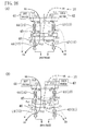
- the refrigerant circuit (20) is configured in the form of a closed circuit along which a compressor (21), an outdoor heat exchanger (22), an expansion mechanism (23), and an indoor heat exchanger (24) are fluidly connected.
- the refrigerant circuit (20) is provided with a four way switching valve (25) as a switching mechanism for reversing the circulation direction of refrigerant flow.
- the outdoor heat exchanger (22) is made up of the first air heat exchanger (11).
- the indoor heat exchanger (24) is made up of the adsorption heat exchanger (13) and the second air heat exchanger (12).
- the expansion mechanism (23) is made up of an expansion valve (31) as a first expansion mechanism by which the refrigerant is reduced in pressure between the first air heat exchanger (11) and the adsorption heat exchanger (13), and a capillary tube (32a) and an electromagnetic valve (32b) which together form a second expansion mechanism (32) by which the refrigerant is reduced in pressure between the adsorption heat exchanger (13) and the second air heat exchanger (12).
- the capillary tube (32a) and the electromagnetic valve (32b) are connected in parallel with each other.
- the second expansion mechanism (32) may be an electric expansion valve.
- the discharge side of the compressor (21) is connected in fluid communication with a first port (P1) of the four way switching valve (25).
- a second port (P2) of the four way switching valve (25) is connected in fluid communication with the first air heat exchanger (11).
- the first expansion mechanism (31), the adsorption heat exchanger (13), the second expansion mechanism (32), and the second air heat exchanger (12) are connected, in that order, in series fluid communication with the first air heat exchanger (11).
- the second air heat exchanger (12) is connected in fluid communication with a third port (P3) of the four way switching valve (25).
- a fourth port (P4) of the four way switching valve (25) is connected in fluid communication with the suction side of the compressor (21).
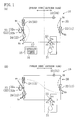
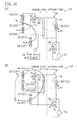
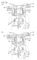
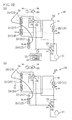
- the four way switching valve (25) is operative to switch between a first state which allows fluid communication between the first port (P1) and the second port (P2) and fluid communication between the third port (P3) and the fourth port (P4) (as indicated by solid line in Figures 1(A) and 1(B) ), and a second state which allows fluid communication between the first port (P1) and the third port (P3) and fluid communication between the second port (P2) and the fourth port (P4) (as indicated by solid line in Figures 2(A) and 2(B) ). Switching of the four way switching valve (25) between the first and second states makes it possible to reverse the direction of refrigerant flow in the refrigerant circuit (20).
- the air conditioning apparatus (10) is provided with a switching mechanism for establishing, during operation, switching between a state in which room air after passage through the adsorption heat exchanger (13) is supplied into an indoor space (see Figures 1(A) and 2(A) ), and a state in which room air after passage through the adsorption heat exchanger (13) is expelled to the outdoors (see Figures 1(B) and 2(B) ).
- the air conditioning apparatus (10) is constructed and configured to be able to perform both a moisture absorbing operation (see Figures 1(A) and 2(B)) and a moisture releasing operation (see Figures 1(B) and 2(A)). More specifically, in the moisture absorbing operation, while cooling the adsorbent in the adsorption heat exchanger (13), moisture in an airstream flowing through the adsorption heat exchanger (13) is adsorbed by the adsorbent. On the other hand, in the moisture releasing operation, while heating the adsorbent in the adsorption heat exchanger (13), moisture is released to an airstream flowing through the adsorption heat exchanger (13) to thereby regenerate the adsorbent.
- the air conditioning apparatus (10) is provided with a controller (control unit) (15).
- This controller (15) controls the four way switching valve (25), the expansion mechanism (23), and the switching mechanism (not shown), thereby changing the flow of refrigerant in the refrigerant circuit (20) and the distribution of air between the moisture absorbing operation and the moisture releasing operation.
- the controller (15) includes a switching timer (switching interval setting part) (16) which sets, depending on the indoor latent heat load, a time interval at which switching between the moisture absorbing operation and the moisture releasing operation is made.
- This switching timer (16) is constructed and configured such that as the latent heat load increases, the time interval at which switching between the moisture absorbing operation and the moisture releasing operation is made is set to a lower value.
- the four way switching valve (25) changes state to the first state.
- a first operation (moisture absorbing operation) of Figure 1(A) and a second operation (moisture releasing operation) of Figure 1(B) are carried out alternately.
- the degree of opening of the expansion valve (31) is reduced to a predetermined value and the electromagnetic valve (32b) is placed in the open state.
- the second operation the expansion valve (31) is placed in the open state and the electromagnetic valve (32b) is placed in the closed state.
- air latent heat processing is performed mainly in the adsorption heat exchanger (13), while air sensible heat processing is performed mainly in the second air heat exchanger (12).
- one part of room air (RA) passing through the indoor heat exchanger (24) flows through the adsorption heat exchanger (13), thereby being mainly dehumidified and then returning into the room, while the remaining other part flows through the second air heat exchanger (12), thereby being mainly cooled and then returning into the room.
- RA room air
- refrigerant discharged out of the compressor (21) condenses in the first air heat exchanger (11) and in the adsorption heat exchanger (13), expands in the capillary tube (32a), evaporates in the second air heat exchanger (12), and is drawn back into the compressor (21).
- a stream of outside air (OA) after passage through the first air heat exchanger (11) is expelled to the outdoors as exhaust air (EA);
- a stream of room air (RA) after passage through the adsorption heat exchanger (13) is expelled to the outdoors as exhaust air (EA); and another stream of room air (RA) after passage through the second air heat exchanger (12) returns into the room as supply air (SA).
- the controller By alternate repetition of the first operation and the second operation in the way described above, it becomes possible to intermittently perform indoor latent heat load processing while continuously performing indoor sensible heat load processing.
- the controller operates such that as the indoor latent heat load increases the time interval at which switching between the first operation and the second operation is accomplished is made to decrease. Consequently, when the indoor latent heat load is large, the frequency of switching is increased to thereby increase the amount of dehumidification so that room comfort is enhanced. On the other hand, when the indoor latent heat load is small, the frequency of switching is decreased to thereby reduce the amount of dehumidification so that energy-savings are enhanced.
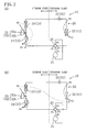
- the four way switching valve (25) changes state to the second state.
- a first operation (moisture releasing operation) of Figure 2(A) and a second operation (moisture absorbing operation) of Figure 2(B) are carried out alternately.
- the degree of opening of the expansion valve (31) is reduced to a predetermined value and the electromagnetic valve (32b) is placed in the open state.
- the second operation the expansion valve (31) is placed in the open state and the electromagnetic valve (32b) is placed in the closed state.
- air latent heat processing is performed mainly in the adsorption heat exchanger (13), while air sensible heat processing is performed mainly in the second air heat exchanger (12).
- one part of the room air (RA) which passes through the indoor heat exchanger (24), when it is flowing through the adsorption heat exchanger (13), regenerates the adsorbent, thereby being mainly humidified and then returning into the room, while the remaining other part flows through the second air heat exchanger (12), thereby being mainly heated and then returning into the room.
- RA room air
- the state is that only indoor sensible heat load processing is mainly performed, while no latent heat load processing is performed. Consequently, room heating is mainly provided.
- the air conditioning apparatus (10) is made up of the refrigerant circuit (20) including the two air heat exchangers (11, 12) and the single adsorption heat exchanger (13). Since it suffices if the adsorption heat exchanger (13) and the second air heat exchanger (12) are provided within the indoor unit, this prevents an increase in apparatus size and cuts down costs, in comparison with the case where an air conditioner and a desiccant type outdoor air makeup unit are separately installed.
- any dedicated means for adsorbent heating is unnecessary, and high-COP operations can be carried out because it is possible to provide cooling/dehumidification or heating/humidification by driving only the refrigerant circuit (20).
- the frequency of switching between the first operation and the second operation is increased if the indoor latent heat load is large, while on the other hand the frequency of switching between the first operation and the second operation is decreased if the indoor latent heat load is small.
- the frequency of switching between the first operation and the second operation is decreased if the indoor latent heat load is small.
- an air conditioning apparatus is an example obtained by modification of the configuration of the refrigerant circuit (20) of the first embodiment.
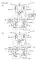
- the refrigerant circuit (20) of the second embodiment includes, as a plurality of heat exchangers (11, 13, 14) for effecting refrigerant/air heat exchange, a single air heat exchanger (11) and two adsorption heat exchangers (13,14).
- the adsorption heat exchangers (13, 14) mainly perform air latent heat processing, but they also perform sensible heat processing.
- the refrigerant circuit (20) of the present embodiment is configured into a closed circuit along which a compressor (21), an outdoor heat exchanger (22), an expansion mechanism (23), and an indoor heat exchanger (24) are fluidly connected.
- the refrigerant circuit (20) is provided with a four way switching valve (25, 26) as a switching mechanism for reversing the circulation direction of refrigerant flow.
- the outdoor heat exchanger (22) is made up of the air heat exchanger (11).
- the indoor heat exchanger (24) is made up of the first adsorption heat exchanger (13) and the second adsorption heat exchanger (14) which are connected in series fluid communication with each other by way of the expansion mechanism (23).
- the expansion mechanism (23) is made up of an expansion valve.
- the switching mechanism (25, 26) is made up of a first four way switching valve (first switching mechanism) (25) for reversing the general circulation direction of refrigerant flow in the refrigerant circuit (20) and a second four way switching valve (second switching mechanism) (26) for reversing the direction of refrigerant flow between the first adsorption heat exchanger (13) and the second adsorption heat exchanger (14).
- the discharge side of the compressor (21) is connected in fluid communication with a first port (P1) of the first four way switching valve (25).
- a second port (P2) of the first four way switching valve (25) is connected in fluid communication with the air heat exchanger (11).
- the air heat exchanger (11) is connected in fluid communication with a first port (P1) of the second four way switching valve (26).
- a second port (P2) of the second four way switching valve (26) is connected in fluid communication with the first adsorption heat exchanger (13).
- the expansion valve (23) and the second adsorption heat exchanger (14) are sequentially connected in series fluid communication with the first adsorption heat exchanger (13).
- the second adsorption heat exchanger (14) is connected in fluid communication with a third port (P3) of the second four way switching valve (26).
- a fourth port (P4) of the second four way switching valve (26) is connected in fluid communication with a third port (P3) of the first four way switching valve (25).
- a fourth port (P4) of the first four way switching valve (25) is connected in fluid communication with the suction side of the compressor (21).
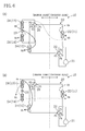
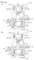
- the first four way switching valve (25) is operative to switch between a first state which allows fluid communication between the first port (P1) and the second port (P2) and fluid communication between the third port (P3) and the fourth port (P4) (as indicated by solid line in Figures 3(A) and 3(B)), and a second state which allows fluid communication between the first port (P1) and the third port (P3) and fluid communication between the second port (P2) and the fourth port (P4) (as indicated by solid line in Figures 4(A) and 4(B) ).
- the second four way switching valve (26) is operative to switch between a first state which allows fluid communication between the first port (P1) and the second port (P2) and fluid communication between the third port (P3) and the fourth port (P4) (as indicated by solid line in Figures 3(A) and 4(A) ), and a second state which allows fluid communication between the first port (P1) and the third port (P3) and fluid communication between the second port (P2) and the fourth port (P4) (as indicated by solid line in Figures 3(B) and 4(B) ).
- the first four way switching valve (25) changes state to the first state.
- a first operation of Figure 3(A) and a second operation of Figure 3(B) are carried out alternately.
- the second four way switching valve (26) changes state to the first state.
- the second four way switching valve (26) changes state to the second state.
- the degree of opening of the expansion valve (23) is reduced to a predetermined value.
- a stream of outside air (OA) after passage through the air heat exchanger (11) is expelled to the outdoors as exhaust air (EA);
- a stream of room air (RA) after passage through the first adsorption heat exchanger (13) is expelled to the outdoors as exhaust air (EA);
- a stream of room air (RA) after passage through the second adsorption heat exchanger (14) returns into the room as supply air (SA).
- the second adsorption heat exchanger (14) performs air latent heat processing and air sensible heat processing.
- a stream of room air (RA) which passes through the second adsorption heat exchanger (14) is mainly moisture-adsorbed by the adsorbent, is gradually cooled, and is then returned into the room.
- another stream of room air (RA) passing through the first adsorption heat exchanger (13) regenerates, during its passage therethrough, the adsorbent, and is expelled to the outdoors.
- a stream of outside air (OA) after passage through the air heat exchanger (11) is expelled to the outdoors as exhaust air (EA);
- a stream of room air (RA) after passage through the first adsorption heat exchanger (13) returns into the room as supply air (SA); and
- another stream of room air (RA) after passage through the second adsorption heat exchanger (14) is expelled to the outdoors as exhaust air (EA).
- the first adsorption heat exchanger (13) performs air latent heat processing and air sensible heat processing.
- a stream of room air (RA) which passes through the first adsorption heat exchanger (13) is mainly moisture-adsorbed by the adsorbent, is gradually cooled, and is then returned into the room.
- another stream of room air (RA) passing through the second adsorption heat exchanger (14) regenerates, during its passage therethrough, the adsorbent, and is expelled to the outdoors.
- the controller By alternate repetition of the first operation and the second operation in the way described above, it becomes possible to continuously perform indoor latent heat load processing while continuously performing also indoor sensible heat load processing.
- the controller operates such that as the indoor latent heat load increases the time interval at which switching between the first operation and the second operation is accomplished is made to decrease. Consequently, when the indoor latent heat load is large, the frequency of switching is increased to thereby increase the amount of dehumidification so that room comfort is enhanced. On the other hand, when the indoor latent heat load is small, the frequency of switching is decreased to thereby reduce the amount of dehumidification so that energy-savings are enhanced.
- the first four way switching valve (25) changes state to the second state.
- a first operation of Figure 4(A) and a second operation of Figure 4(B) are carried out alternately.
- the second four way switching valve (26) changes state to the first state.
- the second four way switching valve (26) changes state to the second state.
- the degree of opening of the expansion valve (23) is reduced to a predetermined value.
- a stream of outside air (OA) after passage through the air heat exchanger (11) is expelled to the outdoors as exhaust air (EA);
- a stream of room air (RA) after passage through the first adsorption heat exchanger (13) is expelled to the outdoors as exhaust air (EA);
- another stream of room air (RA) after passage through the second adsorption heat exchanger (14) returns into the room as supply air (SA).
- the second adsorption heat exchanger (14) performs air latent processing and air sensible heat processing.
- a stream of room air (RA) which passes through the second adsorption heat exchanger (14) mainly regenerates the adsorbent, thereby being humidified. Subsequently, this room air stream is gradually heated and returns into the room.
- another stream of room air (RA) which passes through the first adsorption heat exchanger (13) gives, during its passage therethrough, moisture to the adsorbent and is then expelled to the outdoors.
- a stream of outside air (OA) after passage through the air heat exchanger (11) is expelled to the outdoors as exhaust air (EA);
- a stream of room air (RA) after passage through the first adsorption heat exchanger (13) returns into the room as supply air (SA); and
- another stream of room air (RA) after passage through the second air heat exchanger (12) is expelled to the outdoors as exhaust air (EA).
- the first adsorption heat exchanger (13) performs air latent heat processing and air sensible heat processing.
- a stream of room air (RA) which passes through the first adsorption heat exchanger (13) mainly regenerates the adsorbent, thereby being humidified. Subsequently, this room air stream is gradually heated and returns into the room.
- another stream of room air (RA) which passes through the second adsorption heat exchanger (14) gives, during its passage therethrough, moisture to the adsorbent and is then expelled to the outdoors.
- the same effects that the first embodiment provides are obtained. Besides, it becomes possible to continuously perform indoor latent heat load processing and indoor sensible heat load processing. This makes it possible to more stably provide room humidity control, when compared to the first embodiment.
- an air conditioning apparatus (10) according to a third embodiment of the present invention is an example obtained by modification of the configuration of the refrigerant circuit (20) of the first and second embodiments.
- the refrigerant circuit (20) of the present embodiment includes, as a plurality of heat exchangers (11, 12, 13, 14) for effecting refrigerant/air heat exchange, two air heat exchangers (11,12) which mainly perform air sensible heat processing and two adsorption heat exchangers (13, 14) which mainly perform air latent heat processing.
- the refrigerant circuit (20) of the present embodiment is a closed circuit along which a compressor (21), an outdoor heat exchanger (22), an expansion mechanism (23), and an indoor heat exchanger (24) are fluidly connected.
- the refrigerant circuit (20) is provided with a four way switching valve (25, 26) as a switching mechanism for reversing the circulation direction of refrigerant flow.
- the outdoor heat exchanger (22) is made up of the first air heat exchanger (11).
- the indoor heat exchanger (24) is made up of the first adsorption heat exchanger (13) and the second adsorption heat exchanger (14) which are connected in series fluid communication with each other by way of the expansion mechanism (23), and the second air heat exchanger (12).
- the switching mechanism (25, 26) is made up of a first four way switching valve (first switching mechanism) (25) for reversing the general circulation direction of refrigerant flow in the refrigerant circuit (20) and a second four way switching valve (second switching mechanism) (26) for reversing the direction of refrigerant flow between the first adsorption heat exchanger (13) and the second adsorption heat exchanger (14).
- first switching mechanism for reversing the general circulation direction of refrigerant flow in the refrigerant circuit (20)
- second switching mechanism second switching mechanism
- the discharge side of the compressor (21) is connected in fluid communication with a first port (P1) of the first four way switching valve (25).
- a second port (P2) of the first four way switching valve (25) is connected in fluid communication with the first air heat exchanger (11).
- the first air heat exchanger (11) is connected in fluid communication with a first port (P1) of the second four way switching valve (26).
- a second port (P2) of the second four way switching valve (26) is connected in fluid communication with the first adsorption heat exchanger (13).
- the expansion valve (23) and the second adsorption heat exchanger (14) are sequentially connected in series fluid communication with the first adsorption heat exchanger (13).
- the second adsorption heat exchanger (14) is connected in fluid communication with a third port (P3) of the second four way switching valve (26).
- a fourth port (P4) of the second four way switching valve (26) is connected in fluid communication by way of the second air heat exchanger (12) with a third port (P3) of the first four way switching valve (25).
- a fourth port (P4) of the first four way switching valve (25) is connected in fluid communication with the suction side of the compressor (21).
- the first four way switching valve (25) is operative to switch between a first state which allows fluid communication between the first port (P1) and the second port (P2) and fluid communication between the third port (P3) and the fourth port (P4) (as indicated by solid line in Figures 5(A) and 5(B) ), and a second state which allows fluid communication between the first port (P1) and the third port (P3) and fluid communication between the second port (P2) and the fourth port (P4) (as indicated by solid line in Figures 6(A) and 6(B) ).
- the second four way switching valve (26) is operative to switch between a first state which allows fluid communication between the first port (P1) and the second port (P2) and fluid communication between the third port (P3) and the fourth port (P4) (as indicated by solid line in Figures 5(A) and 6(A) ), and a second state which allows fluid communication between the first port (P1) and the third port (P3) and fluid communication between the second port (P2) and the fourth port (P4) (as indicated by solid line in Figures 5(B) and 6(B)).
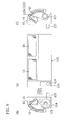
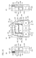
- the air conditioning apparatus (10) is made up of an outdoor unit (110) which is installed outdoors, an indoor unit (120) mounted on an indoor wall, and an interunit line (130) for establishing fluid communication between the outdoor unit (110) and the indoor unit (120).
- the outdoor unit (110) includes the first air heat exchanger (11) which is the outdoor heat exchanger (22) and an outdoor fan (111) for supplying air to the outdoor heat exchanger (22).
- the indoor unit (120) includes: the first adsorption heat exchanger (13), the second adsorption heat exchanger (14), and the second air heat exchanger (12) which together form the indoor heat exchanger (24); an indoor fan (121) for supplying air to the indoor heat exchanger (24); and a damper (122) for air passage switching in the indoor unit (120).
- the adsorption heat exchangers (13, 14) are disposed on the backside, while the second air heat exchanger (12) is disposed on the front side.
- the second air heat exchanger (12) is made up of two heat exchangers.
- the indoor unit (120) includes an air exhaust pipe (123) in fluid communication with the outdoors and an air exhaust fan (124) for discharging air to the outdoors from the air exhaust pipe (123).
- the damper (122) is composed of a first damper (122a) in association with the first adsorption heat exchanger (13) and a second damper (122b) in association with the second adsorption heat exchanger (14).
- the dampers (122a, 122b) are configured such that each damper is operative to switch between a first position which allows a stream of room air (RA) after passage through the adsorption heat exchanger (13,14) to be supplied into the room by way of the indoor fan (121), and a second position which allows a stream of room air (RA) after passage through the adsorption heat exchanger (13,14) to be discharged to the outdoors by way of the air exhaust fan (124) and the air exhaust pipe (123).
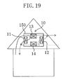
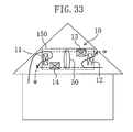
- Figure 9 is a conceptual illustration which shows an installation state of the air conditioning apparatus (10) as well as depicting air flow during operation.
- a stream of room air (RA) after passage through one of the first and second adsorption heat exchangers (13, 14) is expelled to the outdoors, while another stream of room air (RA) after passage through the other adsorption heat exchanger and still another stream of room air (RA) after passage through the second air heat exchanger (12) circulate in the room.
- a stream of outside air (OA) passes through the first air heat exchanger (11) and circulates outside the room.
- the first four way switching valve (25) changes state to the first state.
- a first operation of Figure 5(A) and a second operation of Figure 5(B) are carried out alternately.
- the second four way switching valve (26) changes state to the first state.
- the second four way switching valve (26) changes state to the second state.
- the degree of opening of the expansion valve (23) is reduced to a predetermined value.
- a stream of outside air (OA) after passage through the first air heat exchanger (11) is expelled to the outdoors as exhaust air (EA);
- a stream of room air (RA) after passage through the first adsorption heat exchanger (13) is expelled to the outdoors as exhaust air (EA);
- another stream of room air (RA) after passage through the second adsorption heat exchanger (14) and still another stream of room air (RA) after passage through the second air heat exchanger (12) each return into the room as supply air (SA).
- SA supply air
- a stream of outside air (OA) after passage through the first air heat exchanger (11) is expelled to the outdoors as exhaust air (EA);
- a stream of room air (RA) after passage through the second adsorption heat exchanger (14) is expelled to the outdoors as exhaust air (EA);
- a stream of room air (RA) after passage through the first adsorption heat exchanger (13) and another stream of room air (RA) after passage through the second air heat exchanger (12) each return into the room as supply air (SA).
- SA supply air
- the first four way switching valve (25) changes state to the second state.
- a first operation of Figure 6(A) and a second operation of Figure 6(B) are carried out alternately.
- the second four way switching valve (26) changes state to the first state.
- the second four way switching valve (26) changes state to the second state.
- the degree of opening of the expansion valve (23) is reduced to a predetermined value.
- a stream of outside air (OA) after passage through the first air heat exchanger (11) is expelled to the outdoors as exhaust air (EA);
- a stream of room air (RA) after passage through the first adsorption heat exchanger (13) is expelled to the outdoors as exhaust air (EA);
- another stream of room air (RA) after passage through the second adsorption heat exchanger (14) and still another stream of room air (RA) after passage through the second air heat exchanger (12) each return into the room as supply air (SA).
- SA supply air
- air latent heat processing is performed mainly in the second adsorption heat exchanger (14), while air sensible heat processing is processed mainly in the second air heat exchanger (12).
- room air (RA) which passes through the indoor heat exchanger (24) is humidified mainly by passage through the second adsorption heat exchanger (14) and returns into the room, while the other part is heated mainly by passage through the second air heat exchanger (12) and returns into the room.
- EA exhaust air
- which is expelled to the outdoors after passage through the indoor heat exchanger (24) gives moisture to the adsorbent when passing through the first adsorption heat exchanger (13).
- a stream of outside air (OA) after passage through the first air heat exchanger (11) is expelled to the outdoors as exhaust air (EA);
- a stream of room air (RA) after passage through the second adsorption heat exchanger (14) is expelled to the outdoors as exhaust air (EA);
- a stream of room air (RA) after passage through the first adsorption heat exchanger (13) and another stream of room air (RA) after passage through the second air heat exchanger (12) each return into the room as supply air (SA).
- SA supply air
- the third embodiment during both of the cooling and dehumidification operating mode and the heating and humidification operating mode, by switching between the first adsorption heat exchanger (13) and the second adsorption heat exchanger (14), either one of them is used to perform latent heat processing, thereby making it possible to continuously performing indoor latent heat load processing. Additionally, indoor sensible heat load processing can be performed continuously in the second air heat exchanger (12). Accordingly, in comparison with the first embodiment, it becomes possible to more stably control room humidity, and it also becomes possible to more stably control room temperature in comparison with the second embodiment.
- an air conditioning apparatus (10) according to a fourth embodiment of the present invention is an example obtained by modification of the configuration of the refrigerant circuit (20) of the first to third embodiments.
- the refrigerant circuit (20) of the present embodiment includes, as a plurality of heat exchangers (11, 12, 13,14) for effecting refrigerant/air heat exchange, two air heat exchangers (11, 12) which mainly perform air sensible heat processing and two adsorption heat exchangers (13, 14) which mainly perform air latent heat processing, as in the third embodiment.
- the refrigerant circuit (20) of the present embodiment is a closed circuit along which a compressor (21), an outdoor heat exchanger (22), an expansion mechanism (23), and an indoor heat exchanger (24) which are connected in fluid communication.
- the refrigerant circuit (20) is provided with a four way switching valve (25, 26) as a switching mechanism for reversing the circulation direction of refrigerant flow.
- the expansion mechanism (23) is made up of a first expansion valve (first expansion mechanism) (31) and a second expansion valve (second expansion mechanism) (32).
- the outdoor heat exchanger (22) is made up of the first air heat exchanger (11).
- the indoor heat exchanger (24) is made up of the first adsorption heat exchanger (13) and the second adsorption heat exchanger (14) which are connected in series fluid communication with each other by way of the second expansion mechanism (32), and the second air heat exchanger (12).
- the switching mechanism (25, 26) is made up of a first four way switching valve (first switching mechanism) (25) for reversing the general circulation direction of refrigerant flow in the refrigerant circuit (20), and a second four way switching valve (second switching mechanism) (26) for reversing the direction of refrigerant flow between the first adsorption heat exchanger (13) and the second adsorption heat exchanger (14).
- first switching mechanism for reversing the general circulation direction of refrigerant flow in the refrigerant circuit (20)
- second switching mechanism second switching mechanism
- the discharge side of the compressor (21) is connected in fluid communication with a first port (P1) of the first four way switching valve (25).
- a second port (P2) of the first four way switching valve (25) is connected in fluid communication with the first air heat exchanger (11).
- the first expansion valve (31) and the second air heat exchanger (12) are sequentially connected in series fluid communication with the first air heat exchanger (11).
- the second air heat exchanger (12) is connected in fluid communication with a third port (P3) of the first four way switching valve (25).
- a fourth port (P4) of the first four way switching valve (25) is connected in fluid communication with the suction side of the compressor (21).
- a first port (P1) of the second four way switching valve (26) is connected in fluid communication with the second port (P2) of the first four way switching valve (25).
- the first adsorption heat exchanger (13), the second expansion valve (32), and the second adsorption heat exchanger (14) are sequentially connected in series fluid communication with a second port (P2) of the second four way switching valve (26).
- the second adsorption heat exchanger (14) is connected in fluid communication with a third port (P3) of the second four way switching valve (26).
- a fourth port (P4) of the second four way switching valve (26) is fluidly connected, in parallel with the second air heat exchanger (12), to the first port (P1) of the first four way switching valve (25).
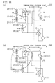
- the compressor (21), the first air heat exchanger (11), the first expansion mechanism (31), and the second air heat exchanger (12) are fluidly connected in sequence, and the first adsorption heat exchanger (13), the second expansion mechanism (32), and the second adsorption heat exchanger (14) are fluidly connected in parallel with the first air heat exchanger (11), the first expansion mechanism (31), and the second air heat exchanger (12).
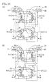
- the first four way switching valve (25) is operative to switch between a first state which allows fluid communication between the first port (P1) and the second port (P2) and fluid communication between the third port (P3) and the fourth port (P4) (as indicated by solid line in Figures 10(A) and 10(B) ), and a second state which allows fluid communication between the first port (P1) and the third port (P3) and fluid communication between the second port (P2) and the fourth port (P4) (as indicated by solid line in Figures 11(A) and 11(B)).
- the second four way switching valve (26) is operative to switch between a first state which allows fluid communication between the first port (P1) and the second port (P2) and fluid communication between the third port (P3) and the fourth port (P4) (as indicated by solid line in Figures 10(A) and 11(A)), and a second state which allows fluid communication between the first port (P1) and the third port (P3) and fluid communication between the second port (P2) and the fourth port (P4) (as indicated by solid line in Figures 10(B) and 11(B) ).
- the first four way switching valve (25) changes state to the first state.
- a first operation of Figure 10(A) and a second operation of Figure 10(B) are carried out alternately.
- the second four way switching valve (26) changes state to the first state.
- the second four way switching valve (26) changes state to the second state.
- the degree of opening of each of the first and second expansion valves (31, 32) is reduced to a respective predetermined value.
- a stream of outside air (OA) after passage through the first air heat exchanger (11) is expelled to the outdoors as exhaust air (EA);
- a stream of room air (RA) after passage through the first adsorption heat exchanger (13) is expelled to the outdoors as exhaust air (EA), another stream of room air (RA) after passage through the second adsorption heat exchanger (14) and still another stream of room air (RA) after passage through the second air heat exchanger (12) each return into the room as supply air (SA).
- SA supply air
- a stream of outside air (OA) after passage through the first air heat exchanger (11) is expelled to the outdoors as exhaust air (EA);
- a stream of room air (RA) after passage through the second adsorption heat exchanger (14) is expelled to the outdoors as exhaust air (EA);
- a stream of room air (RA) after passage through the first adsorption heat exchanger (13) and another stream of room air (RA) after passage through the second air heat exchanger (12) each return into the room as supply air (SA).
- SA supply air
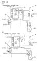
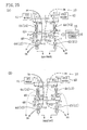
- the first four way switching valve (25) changes state to the second state.
- a first operation of Figure 11(A) and a second operation of Figure 11(B) are carried out alternately.
- the second four way switching valve (26) changes state to the first state.
- the second four way switching valve (26) changes state to the second state.
- the degree of opening of the expansion valve (23) is reduced to a predetermined value.
- a stream of outside air (OA) after passage through the first air heat exchanger (11) is expelled to the outdoors as exhaust air (EA);
- a stream of room air (RA) after passage through the first adsorption heat exchanger (13) is expelled to the outdoors as exhaust air (EA);
- a stream of room air (RA) after passage through the second adsorption heat exchanger (14) and another stream of room air (RA) after passage through the second air heat exchanger (12) each return into the room as supply air (SA).
- SA supply air
- one part of refrigerant discharged out of the compressor (21) condenses in the second air heat exchanger (12). Subsequently, the one part of the refrigerant expands in the first expansion valve (31), evaporates in the first air heat exchanger (11), and is drawn back into the compressor (21). The remaining other part of the refrigerant discharged out of the compressor (21) condenses in the first adsorption heat exchanger (13). Subsequently, the remaining other part of the refrigerant expands in the second expansion valve (32), evaporates in the second adsorption heat exchanger (14), and returns into the compressor (21).
- a stream of outside air (OA) after passage through the first air heat exchanger (11) is expelled to the outdoors as exhaust air (EA);
- a stream of room air (RA) after passage through the second adsorption heat exchanger (14) is expelled to the outdoors as exhaust air (EA);
- another stream of room air (RA) after passage through the first adsorption heat exchanger (13) and still another stream of room air (RA) after passage through the second air heat exchanger (12) each return into the room as supply air (SA).
- SA supply air
- the fourth embodiment during both of the cooling and dehumidification operating mode and the heating and humidification operating mode, by switching between the first adsorption heat exchanger (13) and the second adsorption heat exchanger (14), either one of them is used to perform latent heat processing, thereby making it possible to continuously perform indoor latent heat load processing. Additionally, it is possible to perform indoor sensible heat load processing in the second air heat exchanger (12). Accordingly, like the third embodiment, it becomes possible to stably control room humidity and it also becomes possible to stably control room temperature.
- the flow rate of refrigerant flowing through the air heat exchangers (11, 12) and the flow rate of refrigerant flowing through the adsorption heat exchangers (13,14) are controlled, respectively, by the expansion valve (31) and by the expansion valve (32). This facilitates the control of performing indoor latent load processing and sensible heat load processing, when compared to the third embodiment.
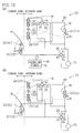
- an air conditioning apparatus (10) according to a fifth embodiment of the present invention is provided with a refrigerant circuit (20) having the same configuration as that of the refrigerant circuit (20) of the fourth embodiment.
- the present embodiment is an example in which the first adsorption heat exchanger (13) and the second adsorption heat exchanger (14) are both installed outdoors.
- the outdoor heat exchanger (22) is made up of the first air heat exchanger (11), the first adsorption heat exchanger (13), and the second adsorption heat exchanger (14), while the indoor heat exchanger (24) is made up of the second air heat exchanger (12) alone.
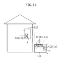
- the air conditioning apparatus (10) of the present embodiment is in the form of an air conditioning apparatus of the air supply fan type in which the amount of air which is supplied to an indoor space exceeds the amount of air which is expelled to the outdoors.
- the refrigerant circuitry of the present embodiment is the same as that of the fourth embodiment, and its specific description is omitted here.
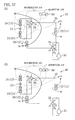
- Figure 14 is a conceptual diagram which illustrates an installation state of the air conditioning apparatus (10) as well as depicting air flow during operation.
- a stream of outside air (OA) which passes through one of the first and second adsorption heat exchangers (13, 14) is supplied into the room, while a stream of outside air (OA) which passes through the other adsorption heat exchanger and another stream of outside air (OA) which passes through the first air heat exchanger (11) circulate outside the room.
- a stream of room air (RA) passes through the second air heat exchanger (12) and circulates in the room.
- a first operation of Figure 12 (A) and a second operation of Figure 12 (B) are carried out alternately.
- the first air heat exchanger (11) and the first adsorption heat exchanger (13) operate as condensers
- the second air heat exchanger (12) and the second adsorption heal exchanger (14) operate as evaporators.
- a stream of outside air (OA) after passage through the first air heat exchanger (11) and another stream of outside air (OA) after passage through the first adsorption heat exchanger (13) are each expelled to the outdoors as exhaust air (EA); still another stream of outside air (OA) after passage through the second adsorption heat exchanger (14) is supplied as supply air (SA); and a stream of room air (RA) after passage through the second air heat exchanger (12) returns into the room as supply air (SA).
- air latent heat processing is performed mainly in the second adsorption heat exchanger (14), while air sensible heat processing is performed mainly in the second air heat exchanger (12).
- one part of outside air (OA) is dehumidified mainly by passage through the second adsorption heat exchanger (14) and supplied into the room, while room air (RA) is cooled mainly by passage through the second air heat exchanger (12) and returns into the room.
- room air (RA) room air
- RA room air
- another part of outside air (OA) regenerates the adsorbent when passing through the first adsorption heat exchanger (13).
- the first air heat exchanger (11) and the second adsorption heat exchanger (14) operate as condensers, while the second air heat exchanger (12) and the first adsorption heat exchanger (13) operate as evaporators.
- a stream of outside air (OA) after passage through the first air heat exchanger (11) and another stream of outside air (OA) after passage through the second adsorption heat exchanger (14) are each expelled to the outdoors as exhaust air (EA); still another stream of outside air (OA) after passage through the first adsorption heat exchanger (13) is supplied to the room as supply air (SA); a stream of room air (RA) after passage through the second air heat exchanger (12) also returns into the room as supply air (SA).
- air latent heat processing is performed mainly in the first adsorption heat exchanger (13), while air sensible heat processing is performed mainly in the second air heat exchanger (12).
- one part of outside air (OA) is dehumidified mainly by passage through the first adsorption neat exchanger (13) and supplied into the room, while room air (RA) is cooled mainly by passage through the second air heat exchanger (12) and returns into the room.
- room air (RA) room air
- RA room air
- another part of outside air (OA) regenerates the adsorbent when passing through the second adsorption heat exchanger (14).
- a first operation of Figure 13(A) and a second operation of Figure 13(B) are carried out alternately.
- the second air heat exchanger (12) and the second adsorption heat exchanger (14) operate as condensers, while the first air heat exchanger (11) and the first adsorption heat exchanger (13) operate as evaporators.
- a stream of outside air (OA) after passage through the first air heat exchanger (11) and another stream of outside air (OA) after passage through the first adsorption heat exchanger (13) are each expelled to the outdoors as exhaust air (EA); still another stream of outside air (OA) after passage through the second adsorption heat exchanger (14) is supplied to the room as supply air (SA); and a stream of room air (RA) after passage through the second air heat exchanger (12) returns into the room as supply air (SA).
- air latent heat processing is performed mainly in the second adsorption heat exchanger (14), while air sensible heat processing is performed mainly in the second air heat exchanger (12).
- one part of outside air (OA) is humidified mainly by passage through the second adsorption heat exchanger (14) and supplied into the room, while room air (RA) is heated mainly by passage through the second air heat exchanger (12) and returns into the room.
- room air (RA) is heated mainly by passage through the second air heat exchanger (12) and returns into the room.
- the second air heat exchanger (12) and the first adsorption heat exchanger (13) operate as condensers, while the first air heat exchanger (11) and the second adsorption heat exchanger (14) operate as evaporators.
- a stream of outside air (OA) after passage through the first air heat exchanger (11) and another stream of outside air (OA) after passage through the second adsorption heat exchanger (14) are each expelled to the outdoors as exhaust air (EA); still another stream of outside air (OA) after passage through the first adsorption heat exchanger (13) is supplied to the room as supply air (SA); and a stream of room air (RA) after passage through the second air heat exchanger (12) returns into the room as supply air (SA).
- air latent heat processing is performed mainly in the first adsorption heat exchanger (13), while air sensible heat processing is performed mainly in the second air heat exchanger (12).
- one part of outside air (OA) is humidified mainly by passage through the first adsorption heat exchanger (13) and supplied into the room, while room air (RA) is heated mainly by passage through the second air heat exchanger (12) and returns into the room. This makes it possible to efficiently provide room heating and humidification.
- another part of outside air (OA) gives, when it is passing through the second adsorption heat exchanger (14), moisture to the adsorbent.
- the present invention is applicable in air conditioning apparatus of the air supply fan type. Also in such a case, the same effects that each of the above-described embodiments provides are obtained.
- an air conditioning apparatus of a sixth embodiment of the present invention is identical in refrigerant circuitry with the fourth embodiment. Additionally, the air conditioning apparatus (10) of the present embodiment is in the form of an air conditioning apparatus of the air ventilation fan type in which the amount of air which is supplied to an indoor space is in balance with the amount of air which is expelled to the outdoors.
- FIG 17 is a conceptual diagram which illustrates an installation state of the air conditioning apparatus (10) as well as depicting air flow during operation.
- a stream of outside air (OA) passing through one of the first and second adsorption heat exchangers (13, 14) is supplied to the room, while a stream of room air (RA) passing through the other adsorption heat exchanger is expelled to outside the room.
- RA room air
- another stream of room air (RA) passing through the second air heat exchanger (12) circulates in the room.
- a stream of outside air (OA) passes through the first air heat exchanger (11) and circulates outside the room.
- a first operation of Figure 15(A) and a second operation of Figure 15(B) are carried out alternately.
- the first air heat exchanger (11) and the first adsorption heat exchanger (13) operate as condensers, while the second air heat exchanger (12) and the second adsorption heat exchanger (14) operate as evaporators.
- a stream of outside air (OA) after passage through the first air heat exchanger (11) is expelled to the outdoors as exhaust air (EA);
- a stream of room air (RA) after passage through the second air heat exchanger (12) returns into the room as supply air (SA);
- another stream of room air (RA) after passage through the first adsorption heat exchanger (13) is expelled to the outdoors as exhaust air (EA);
- another stream of outside air (OA) after passage through the second adsorption heat exchanger (14) is supplied to the room as supply air (SA).
- air latent heat processing is performed mainly in the second adsorption heat exchanger (14), while air sensible heat processing is performed mainly in the second air heat exchanger (12).
- one part of outside air (OA) is dehumidified mainly by passage through the second adsorption heat exchanger (14) and is supplied to the room, while one part of room air (RA) is cooled mainly by passage through the second air heat exchanger (12) and returns into the room.
- OA outside air
- RA room air
- Another part of room air (RA) regenerates, when it is passing through the first adsorption heat exchanger (13), the adsorbent.
- the first air heat exchanger (11) and the second adsorption heat exchanger (14) operate as condensers, while the second air heat exchanger (12) and the first adsorption heat exchanger (13) operate as evaporators.
- a stream of outside air (OA) after passage through the first air heat exchanger (11) is expelled to the outdoors as exhaust air (EA), while a stream of room air (RA) after passage through the second air heat exchanger (12) returns into the room as supply air (SA).
- SA supply air
- SA supply air
- RA room air
- air latent heat processing is performed mainly in the first adsorption heat exchanger (13), while air sensible heat processing is performed mainly in the second air heat exchanger (12).
- one part of outside air (OA) is dehumidified mainly by passage through the first adsorption heat exchanger (13) and is supplied to the room, while one part of room air (RA) is cooled mainly by passage through the second air heat exchanger (12) and returns into the room.
- OA outside air
- RA room air
- RA room air regenerates, when it is passing through the second adsorption heat exchanger (14), the adsorbent.
- a first operation of Figure 16(A) and a second operation of Figure 16(B) are carried out alternately.
- the second air heat exchanger (12) and the second adsorption heat exchanger (14) operate as condensers, while the first air heat exchanger (11) and the first adsorption heat exchanger (13) operate as evaporators.
- a stream of outside air (OA) after passage through the first air heat exchanger (11) is expelled to the outdoors as exhaust air (EA), while a stream of room air (RA) after passage through the second air heat exchanger (12) returns into the room as supply air (SA).
- SA supply air
- air latent heat processing is performed mainly in the second adsorption heat exchanger (14), while air sensible heat processing is performed mainly in the second air heat exchanger (12).
- one part of outside air (OA) is humidified mainly by passage through the second adsorption heat exchanger (14) and is supplied to the room, while one part of room air (RA) is heated mainly by passage through the second air heat exchanger (12) and returns into the room.
- OA outside air
- RA room air
- Another part of room air (RA) gives, when it is passing through the first adsorption heat exchanger (13), moisture to the adsorbent.
- the second air heat exchanger (12) and the first adsorption heat exchanger (13) operate as condensers, while the first air heat exchanger (11) and the second adsorption heat exchanger (14) operate as evaporators.
- a stream of outside air (OA) after passage through the first air heat exchanger (11) is expelled to the outdoors as exhaust air (EA), while a stream of room air (RA) after passage through the second air heat exchanger (12) returns into the room as supply air (SA).
- SA supply air
- SA supply air
- RA room air
- air latent heat processing is performed mainly in the first adsorption heat exchanger (13), while air sensible heat processing is performed mainly in the second air heat exchanger (12).
- one part of outside air (OA) is humidified mainly by passage through the first adsorption heat exchanger (13) and is supplied to the room, while one part of room air (RA) is heated mainly by passage through the second air heat exchanger (12) and returns into the room.
- OA outside air
- RA room air
- Another stream of room air (RA) gives, when it is passing through the second adsorption heat exchanger (14), moisture to the adsorbent.
- the present invention is applicable in air conditioning apparatus of the air ventilation fan type. Also in such a case, the same effects that each of the above-described embodiments provides are obtained.
- the two adsorption heat exchangers (13,14) are disposed indoors.
- these adsorption heat exchangers (13, 14) may be disposed outdoors, as shown in Figure 18.
- a stream of outside air (OA) passing through one of the first and second adsorption heat exchangers (13, 14) is supplied to the room, while a stream of room air (RA) passing through the other adsorption heat exchanger is expelled to the outdoors.
- Another stream of room air (RA) passing through the second air heat exchanger (12) circulates in the room.
- outside air (OA) passes through the first air heat exchanger (11) and circulates outside the room.
- FIG. 19 there is shown an integral-type air conditioning apparatus (10) according to a seventh embodiment of the present invention.
- This air conditioning apparatus (10) includes a single casing (150) which contains two air heat exchangers (11, 12) and two adsorption heat exchangers (13, 14) and is installed under the roof.
- the seventh embodiment is one constructional example when the air conditioning apparatus (10) of the present embodiment is formed as a full air ventilation type.
- Figure 19 is a conceptual diagram which illustrates an installation state of the air conditioning apparatus (10) as well as depicting air flow during operation.
- Figure 20(A) is a structural diagram when viewed from above.
- Figure 20(B) is a structural diagram when viewed from the left-hand side.
- Figure 20(C) is a structural diagram when viewed from the right-hand side.
- the casing (150) of the air conditioning apparatus (10) is shaped like a rectangular box.
- One of a pair of end surfaces of the casing (150) is provided with a first suction opening (151) through which outside air (OA) is drawn into the casing (150), and a second suction opening (152) through which room air (RA) is drawn into the casing (150).
- the other end surface of the casing (150) is provided with a first blowout opening (153) through which supply air (SA) is supplied to an indoor space, and a second blowout opening (154) through which exhaust air (EA) is expelled to the outdoors.
- These openings i.e. the first suction opening (151), the second suction opening (152), the first blowout opening (153), and the second blowout opening (154), are connected, respectively, to ducts so that outside air, room air, supply air, and exhaust air flow therethrough.
- the inside of the casing (150) is divided into a heat exchange chamber (160) in which the air heat exchangers (11,12) and the adsorption heat exchangers (13, 14) are disposed, and a machine chamber (170) in which mechanical components including fans (191,192), a compressor (21) et cetera are disposed.
- the heat exchange chamber (160) is divided, in the horizontal direction of the casing (150) in the figure, into three sections. More specifically, an adsorption heat exchanger chamber (161, 162) is formed in the center; a first air heat exchanger chamber (163) is formed on one side of the adsorption heat exchanger chamber (161,162); and a second air heat exchanger chamber (164) is formed on the other side of the adsorption heat exchanger chamber (161, 162).
- the adsorption heat exchanger chamber (161,162) and the air heat exchanger chambers (163, 164) are each divided into two spaces, i.e., upper and low spaces, in their height direction.
- the adsorption heat exchanger chamber (161, 162) is divided into two rows in the cross direction (the vertical direction in the figure), thereby forming a first adsorption heat exchanger chamber (161) and a second adsorption heat exchanger chamber (162).
- the first air heat exchanger (11) is disposed in the upper space of the first air heat exchanger chamber (163).
- the second air heat exchanger (12) is disposed in the upper space of the second air heat exchanger chamber (164).
- the first adsorption heat exchanger (13) is disposed centrally between the upper and lower spaces of the first adsorption heat exchanger chamber (161), while the second adsorption heat exchanger (14) is disposed centrally between the upper and lower spaces of the second adsorption heat exchanger chamber (162).
- Both the upper and lower spaces of the first air heat exchanger chamber (163) are in fluid communication with the first suction opening (151).
- a first damper (181) is disposed in the upper space of the first air heat exchanger chamber (163), such that it lies between the first air heat exchanger chamber (163) and the first adsorption heat exchanger chamber (161), while a second damper (182) is disposed in the upper space of the first air heat exchanger chamber (163), such that it lies between the first air heat exchanger chamber (163) and the second adsorption heat exchanger chamber (162).
- a third damper (183) is disposed in the lower space of the first air heat exchanger chamber (163), such that it lies between the first air heat exchanger chamber (163) and the first adsorption heat exchanger chamber (161), while a fourth damper (184) is disposed in the lower space of the first air heat exchanger chamber (163), such that it lies between the first air heat exchanger chamber (163) and the second adsorption heat exchanger chamber (162).
- Both the upper and lower spaces of the second air heat exchanger chamber (164) are in fluid communication with the second suction opening (152).
- a fifth damper (185) is disposed in the upper space of the second air heat exchanger chamber (164), such that it lies between the second air heat exchanger chamber (164) and the first adsorption heat exchanger chamber (161), while a sixth damper (186) is disposed in the upper space of the second air heat exchanger chamber (164), such that it lies between the second air heat exchanger chamber (164) and the second adsorption heat exchanger chamber (162).
- a seventh damper (187) is disposed in the lower space of the second air heat exchanger chamber (164), such that it lies between the second air heat exchanger chamber (164) and the first adsorption heat exchanger chamber (161)
- an eighth damper (188) is disposed in the lower space of the second air heat exchanger chamber (164), such that it lies between the second air heat exchanger chamber (164) and the second adsorption heat exchanger chamber (162).
- the compressor (21) is disposed centrally in the machine chamber (170) of the casing (150).
- the first fan (191) is disposed on one side of the compressor (21), while the second fan (192) is disposed on the other side of the compressor (21).
- the first fan (191) is in fluid communication with the first blowout opening (153) and the upper space of the second air heat exchanger chamber (164).
- the second fan (192) is in fluid communication with the second blowout opening (154) and the upper space of the first air heat exchanger chamber (163).
- the refrigerant circuit (20) of the present embodiment is configured in the same way as the one as shown in Figures 15 and 16, and the flow of air in each heat exchanger (11, 12, 13, 14) is also the same as the flow of air shown in Figures 15 and 16.
- the difference between the examples of Figures 15 and 16 and the present embodiment is that, whereas in the former the compressor (21) and the first air heat exchanger (11) are disposed outside the room, every equipment is disposed inside the room in the latter.
- a first operation (see Figure 15(A) ) and a second operation (see Figure 15(B) ) are carried out alternately.
- the first air heat exchanger (11) and the first adsorption heat exchanger (13) operate as condensers
- the second air heat exchanger (12) and the second adsorption heat exchanger (14) operate as evaporators.
- the first damper (181), the fourth damper (184), the sixth damper (186), and the seventh damper (187) are placed in the open state
- the second damper (182), the third damper (183), the fifth damper (185), and the eighth damper (188) are placed in the closed state.
- one part of room air (RA) drawn into the casing (150) from the second suction opening (152) is cooled by passage through the second air heat exchanger (12) in the upper space of the second air heat exchanger chamber (164) and is then supplied into the room from the first blowout opening (153) by way of the first fan (191).
- the remaining other part of the room air (RA) drawn into the casing (150) from the second suction opening (152) flows into the first adsorption heat exchanger chamber (161) from the lower space of the second air heat exchanger chamber (164), regenerates the first adsorption heat exchanger (13), flows out to the upper space of the first air heat exchanger chamber (163), and is then expelled to the outdoors from the second blowout opening (154) by way of the second fan (192).
- air latent heat processing is performed mainly in the second adsorption heat exchanger (14), while air sensible heat processing is performed mainly in the second air heat exchanger (12).
- one part of outside air (OA) is dehumidified mainly by passage through the second adsorption heat exchanger (14) and is then supplied to the room, while one part of room air (RA) is cooled mainly by passage through the second air heat exchanger (12) and returns into the room. This makes it possible to efficiently provide room cooling and dehumidification.
- the first air heat exchanger (11) and the second adsorption heat exchanger (14) operate as condensers, while the second air heat exchanger (12) and the first adsorption heat exchanger (13) operate as evaporators.
- the second damper (182), the third damper (183), the fifth damper (185), and the eighth damper (188) are placed in the open state, while the first damper (181), the fourth damper (184), the sixth damper (186), and the seventh damper (187) are placed in the closed state.
- one part of room air (RA) drawn into the casing (150) from the second suction opening (152) is cooled by passage through the second air heat exchanger (12) in the upper space of the second air heat exchanger chamber (164) and is then supplied into the room from the first blowout opening (153) by way of the first fan (191).
- the remaining other part of the room air (RA) drawn into the casing (150) from the second suction opening (152) flows into the second adsorption heat exchanger chamber (162) from the lower space of the second air heat exchanger chamber (164), regenerates the second adsorption heat exchanger (14), flows out to the upper space of the first air heat exchanger chamber (163), and is then expelled to the outdoors from the second blowout opening (154) by way of the second fan (192).
- air latent heat processing is performed mainly in the first adsorption heat exchanger (13), while air sensible heat processing is performed mainly in the second air heat exchanger (12).
- one part of outside air (OA) is dehumidified mainly by passage through the first adsorption heat exchanger (13) and is then supplied to the room, while one part of room air (RA) is cooled mainly by passage through the second air heat exchanger (12) and returns into the room. This makes it possible to efficiently provide room cooling and dehumidification.
- a first operation (see Figure 16(A) ) and a second operation (see Figure 16(B) ) are carried out alternately.
- the first operation the second air heat exchanger (12) and the second adsorption heat exchanger (14) operate as condensers, while the first air heat exchanger (11) and the first adsorption heat exchanger (13) operate as evaporators.
- the first damper (181), the fourth damper (184), the sixth damper (186), and the seventh damper (187) are placed in the open state, while the second damper (182), the third damper (183), the fifth damper (185), and the eighth damper (188) are placed in the closed state.
- one part of room air (RA) drawn into the casing (150) from the second suction opening (152) is heated by passage through the second air heat exchanger (12) in the upper space of the second air heat exchanger chamber (164) and is then supplied to the room from the first blowout opening (153) by way of the first fan (191).
- the remaining other part of the room air (RA) drawn into the casing (150) from the second suction opening (152) flows into the first adsorption heat exchanger chamber (161) from the lower space of the second air heat exchanger chamber (164), gives moisture to the first adsorption heat exchanger (13), flows out to the upper space of the first air heat exchanger chamber (163), and is then expelled to the outdoors from the second blowout opening (154) by way of the second fan (192).
- air latent heat processing is performed mainly in the second adsorption heat exchanger (14), while air sensible heat processing is performed mainly in the second air heat exchanger (12).
- one part of outside air (OA) is humidified mainly by passage through the second adsorption heat exchanger (14) and is then supplied to the room, while one part of room air (RA) is heated mainly by passage through the second air heat exchanger (12) and returns into the room. This makes it possible to efficiently provide room heating and humidification.
- the second air heat exchanger (12) and the first adsorption heat exchanger (13) operate as condensers, while the first air heat exchanger (11) and the second adsorption heat exchanger (14) operate as evaporators.
- the second damper (182), the third damper (183), the fifth damper (185), and the eighth damper (188) are placed in the open state, while the first damper (181), the fourth damper (184), the sixth damper (186), and the seventh damper (187) are placed in the closed state.
- one part of room air (RA) drawn into the casing (150) from the second suction opening (152) is heated by passage through the second air heat exchanger (12) in the upper space of the second air heat exchanger chamber (164) and is then supplied by way of the first fan (191) into the room from the first blowout opening (153).
- air latent heat processing is performed mainly in the first adsorption heat exchanger (13), while air sensible heat processing is performed mainly in the second air heat exchanger (12).
- one part of outside air (OA) is humidified mainly by passage through the first adsorption heat exchanger (13) and is then supplied to the room, while one part of room air (RA) is heated mainly by passage through the second air heat exchanger (12) and returns into the room. This makes it possible to efficiently provide room heating and humidification.
- an air conditioning apparatus is not provided with the refrigerant circuit (20) of the aforesaid embodiments but instead includes a cold and hot water circuit (40) for the flow of cold and hot water.
- the cold and hot water circuit (40) has a plurality of heat exchangers (11, 12, 13,14) for effecting cold and hot water/air heat exchange.
- the cold and hot water circuit (40) is provided, as the heat exchangers (11, 12, 13, 14), with two air heat exchangers (11, 12) which mainly perform air sensible heat processing and two adsorption heat exchangers (13, 14) which mainly perform air latent heat processing.
- the cold and hot water circuit (40) has a hot water source (41), a cold water source (42), an outdoor heat exchanger (43), and indoor heat exchangers (44). And, the outdoor heat exchanger (43) is made up of the first air heat exchanger (11), while the indoor heat exchangers (44) are made up of the second air heat exchanger (12), the first adsorption heat exchanger (13), and the second adsorption heat exchanger (14).
- the first adsorption heat exchanger (13) and the second adsorption heat exchanger (14) are connected in parallel fluid communication with each other, while the first air heat exchanger (11) and the second adsorption heat exchanger (12) are connected in parallel fluid communication with each other.
- the first and the second adsorption heat exchangers (13, 14) and the first and the second air heat exchangers (11, 12) are connected in series fluid communication with the hot water source (41) and the cold water source (42).
- the cold and hot water circuit (40) includes, as a first switching mechanism (45) for switching the direction of cold and hot water flow so that hot water flows through one of the first and second adsorption heat exchangers (13, 14) while cold water flows through the other adsorption heat exchanger, a three way valve (A1) connected in fluid communication with one end of the first adsorption heat exchanger (13), a three way valve (A2) connected in fluid communication with the other end of the first adsorption heat exchanger (13), a three way valve (B1) connected in fluid communication with one end of the second adsorption heat exchanger (14), and a three way valve (B2) connected in fluid communication with the other end of the second adsorption heat exchanger (14).
- a first switching mechanism (45) for switching the direction of cold and hot water flow so that hot water flows through one of the first and second adsorption heat exchangers (13, 14) while cold water flows through the other adsorption heat exchanger
- A1 connected in fluid communication with one
- the cold and hot water circuit (40) includes, as a second switching mechanism (46) for switching the direction of cold and hot water flow so that hot water flows through one of the first and second air heat exchangers (11, 12) while cold water flows through the other air heat exchanger, a three way valve (C1) connected in fluid communication with one end of the first air heat exchanger (11), a three way valve (C2) connected in fluid communication with the other end of the first air heat exchanger (11), a three way valve (D1) connected in fluid communication with one end of the second air heat exchanger (12), and a three way valve (D2) connected in fluid communication with the other end of the second air heat exchanger (12).
- a second switching mechanism (46) for switching the direction of cold and hot water flow so that hot water flows through one of the first and second air heat exchangers (11, 12) while cold water flows through the other air heat exchanger
- C1 connected in fluid communication with one end of the first air heat exchanger (11)
- C2 connected in fluid communication with the other end of the first air heat
- the three way valve (A1) and the three way valve (B1) are connected in parallel fluid communication with the hot water source (41) at their respective hot water inflow ports (Pi1), while the three way valve (A1) and the three way valve (B1) are connected in parallel fluid communication with the cold water source (42) at their respective cold water inflow ports (Pi2).
- the three way valve (A2) and the three way valve (B2), and the three way valve (C1) and the three way valve (D1) are fluidly connected so that the three way valve (C1) and the three way valve (D1) are in parallel with the three way valve (A2) and the three way valve (B2) and, in addition, the three way valve (A2) and the three way valve (B2) are in parallel with the three way valve (C1) and the three way valve (D1).
- a hot water outflow port (Po1) of the three way valve (A2) and a hot water outflow port (Po1) of the three way valve (B2) are in fluid communication with each other, and are in fluid communication with a hot water inflow port (Pi1) of the three way valve (C1) and a hot water inflow port (Pi1) of the three way valve (D1).
- a cold water outflow port (Po2) of the three way valve (A2) and a cold water outflow port (Po2) of the three way valve (B2) are in fluid communication with each other, and are in fluid communication with a cold water inflow port (Pi2) of the three way valve (C1) and a cold water inflow port (Pi2) of the three way valve (D1).
- the three way valve (C2) and the three way valve (D2) are fluidly connected in parallel to the hot water source (41) at their respective hot water outflow ports (Po1), while the three way valve (C2) and the three way valve (D2) are fluidly connected in parallel to the cold water source (42) at their respective cold water outflow ports (Po2).
- a first operation of Figure 21(A) and a second operation of Figure 21(B) are carried out alternately.
- the first operation in each of the three way valves (A1-D2), ports indicated by solid line of Figure 21(A) are placed in the open state, while a port indicated by broken line of Figure 21(A) is placed in the closed state, as a result of which the first air heat exchanger (11) and the second adsorption heat exchanger (14) operate as heaters, while the second air heat exchanger (12) and the first adsorption heat exchanger (13) operates as coolers.
- a stream of outside air (OA) which has passed through the first air heat exchanger (11) is expelled to the outdoors as exhaust air (EA), while a stream of room air (RA) which has passed through the second air heat exchanger (12) returns into the room as supply air (SA).
- SA exhaust air
- RA room air
- another stream of outside air (OA) which has passed through the first adsorption heat exchanger (13) is supplied to the room as supply air (SA)
- another stream of room air (RA) which has passed through the second adsorption heat exchanger (14) is expelled to the outdoors as exhaust air (EA).
- air latent heat processing is performed mainly in the first adsorption heat exchanger (13), while air sensible heat processing is performed mainly in the second air heat exchanger (12).
- one part of outside air (OA) is dehumidified mainly by passage through the first adsorption heat exchanger (13) and is then supplied to the room, while one part of room air (RA) is cooled mainly by passage through the second air heat exchanger (12) and returns into the room.
- OA outside air
- RA room air
- RA room air regenerates, when it is passing through the second adsorption heat exchanger (14), the adsorbent.
- air latent heat processing is performed mainly in the second adsorption heat exchanger (14), while air sensible heat processing is performed mainly in the second air heat exchanger (12).
- one part of outside air (OA) is dehumidified mainly by passage through the second adsorption heat exchanger (14) and is then supplied to the room, while one part of room air (RA) is cooled mainly by passage through the second air heat exchanger (12) and returns into the room.
- OA outside air
- RA room air
- RA room air regenerates, when it is passing through the first adsorption heat exchanger (13), the adsorbent.
- a first operation of Figure 22(A) and a second operation of Figure 22(B) are carried out alternately.
- the first operation in each of the three way valves (A1-D2), ports indicated by solid line of Figure 22(A) are placed in the open state, while a port indicated by broken line of Figure 22(A) is placed in the closed state.
- the second air heat exchanger (12) and the second adsorption heat exchanger (14) operate as heaters
- the first air heat exchanger (11) and the first adsorption heat exchanger (13) operate as coolers.
- a stream of outside air (OA) which has passed through the first air heat exchanger (11) is expelled to the outdoors as exhaust air (EA), while a stream of room air (RA) which has passed through the second air heat exchanger (12) returns into the room as supply air (SA).
- EA exhaust air
- RA room air
- SA supply air
- another stream of room air (RA) which has passed through the first adsorption heat exchanger (13) is expelled to the outdoors as exhaust air (EA)
- another stream of outside air (OA) which has passed through the second adsorption heat exchanger (14) is supplied to the room as supply air (SA).
- air latent heat processing is performed mainly in the second adsorption heat exchanger (14), while air sensible heat processing is performed mainly in the second air heat exchanger (12).
- one part of outside air (OA) is humidified mainly by passage through the second adsorption heat exchanger (14) and is then supplied to the room, while one part of room air (RA) is heated mainly by passage through the second air heat exchanger (12) and returns into the room.
- OA outside air
- RA room air
- Another part of room air (RA) gives, when it is passing through the first adsorption heat exchanger (13), moisture to the adsorbent.
- SA supply air
- RA room air
- air latent heat processing is performed mainly in the first adsorption heat exchanger (13), while air sensible heat processing is performed mainly in the second air heat exchanger (12).
- one part of outside air (OA) is humidified mainly by passage through the first adsorption heat exchanger (13) and is then supplied to the room, while one part of room air (RA) is heated mainly by passage through the second air heat exchanger (12) and returns into the room.
- OA outside air
- RA room air
- RA room air
- regenerates when it is passing through the second adsorption heat exchanger (14), the adsorbent.
- the air conditioning apparatus (10) is of the integral type as in the seventh embodiment in which there is no distinction between the outdoor heat exchanger (43) and the indoor heat exchanger (44).
- an air conditioning apparatus according to a ninth embodiment of the present invention is an example as a result of modification of the configuration of the cold and hot water circuit (40) of the eighth embodiment.
- the cold and hot water circuit (40) of the present embodiment includes a hot water source (41), a cold water source (42), outdoor heat exchangers (43), and indoor heat exchangers (44), wherein the outdoor heat exchangers (43) are made up of the first air heat exchanger (11) and the first adsorption heat exchanger (13), while the indoor heat exchangers (44) are made up of the second air heat exchanger (12) and the second adsorption heat exchanger (14).
- the first adsorption heat exchanger (13) and the second adsorption heat exchanger (14) are connected in parallel fluid communication with each other, while the first air heat exchanger (11) and the second air heat exchanger (12) are in parallel fluid communication with each other.
- the first and the second adsorption heat exchangers (13,14) and the first and the air heat exchangers (11, 12) are connected in parallel fluid communication with the hot water source (41) and the cold water source (42).
- the cold and hot water circuit (40) includes, as a first switching mechanism (45) for switching the direction of cold and hot water flow so that hot water flows through one of the first and second adsorption heat exchangers (13, 14) while cold water flows through the other adsorption heat exchanger, a three way valve (A1) connected in fluid communication with one end of the first adsorption heat exchanger (13), a three way valve (A2) connected in fluid communication with the other end of the first adsorption heat exchanger (13), a three way valve (B1) connected in fluid communication with one end of the second adsorption heat exchanger (14), and a three way valve (B2) connected in fluid communication with the other end of the second adsorption heat exchanger (14).
- a first switching mechanism (45) for switching the direction of cold and hot water flow so that hot water flows through one of the first and second adsorption heat exchangers (13, 14) while cold water flows through the other adsorption heat exchanger
- A1 connected in fluid communication with one
- the cold and hot water circuit (40) includes, as a second switching mechanism (46) for switching the direction of cold and hot water flow so that hot water flows through one of the first and second air heat exchangers (11,12) while cold water flows through the other air heat exchanger, a three way valve (C1) connected in fluid communication with one end of the first air heat exchanger (11), a three way valve (C2) connected in fluid communication with the other end of the first air heat exchanger (11), a three way valve (D1) connected in fluid communication with one end of the second air heat exchanger (12), and a three way valve (D2) connected in fluid communication with the other end of the second air heat exchanger (12).
- a second switching mechanism (46) for switching the direction of cold and hot water flow so that hot water flows through one of the first and second air heat exchangers (11,12) while cold water flows through the other air heat exchanger
- C1 connected in fluid communication with one end of the first air heat exchanger (11)
- C2 connected in fluid communication with the other end of the first air heat
- the three way valve (A1) and the three way valve (B1) are connected in parallel fluid communication with the hot water source (41) at their respective hot water inflow ports (Pi1), while the three way valve (A1) and the three way valve (B1) are connected in parallel fluid communication with the cold water source (42) at their respective cold water inflow ports (Pi2).
- the three way valve (C1) and the three way valve (D1) are connected in parallel fluid communication with the hot water source (41) at their respective hot water inflow ports (Pi1), while the three way valve (C1) and the three way valve (D1) are connected in parallel fluid communication with the cold water source (42) at their respective cold water inflow ports (Pi2).
- the three way valve (A2) and the three way valve (B2) are connected in parallel fluid communication with the hot water source (41) at their respective hot water outflow ports (Po1), while the three way valve (A2) and the three way valve (B2) are connected in parallel fluid communication with the cold water source (42) at their respective cold water outflow ports (Po2).
- the three way valve (C2) and the three way valve (D2) are connected in parallel fluid communication with the hot water source (41) at their respective hot water outflow ports (Po1), while the three way valve (C2) and the three way valve (D2) are connected in parallel fluid communication with the cold water source (42) at their respective cold water outflow ports (Po2).
- a first operation of Figure 23(A) and a second operation of Figure 23(B) are carried out alternately.
- the first operation in each of the three way valves (A1-D2), ports indicated by solid line of Figure 23(A) are placed in the open state, while a port indicated by broken line of Figure 23(A) is placed in the closed state, as a result of which the first air heat exchanger (11) and the second adsorption heat exchanger (14) operate as heaters, while the second air heat exchanger (12) and the first adsorption heat exchanger (13) operate coolers.
- a first operation of Figure 24(A) and a second operation of Figure 24(B) are carried out alternately.
- the first operation in each of the three way valves (A1-D2) , ports indicated by solid line of Figure 24(A) are placed in the open state, while a port indicated by broken line of Figure 24(A) is placed in the closed state, as a result of which the second air heat exchanger (12) and the second adsorption heat exchanger (14) operate as heaters, while the first air heat exchanger (11) and the first adsorption heat exchanger (13) operate as coolers.
- An air conditioning apparatus (10) is, contrary to the eighth embodiment in which the cold and hot water circuit (40) is a closed-cycle circuit for the circulation of cold and hot water, an example in which the cold and hot water circuit (40) is formed into an open cycle circuit in which cold and hot water is expelled outside, as shown in Figures 25 and 26.
- the cold and hot water circuit (40) is a circuit which is configured such that cold and hot water exiting the first air heat exchanger (11) and cold and hot water exiting the second air heat exchanger (12) are returned neither to the hot water source (41) nor to the cold water source (42) but are expelled outside.
- An air conditioning apparatus (10) is an example in which, as illustrated in Figures 27 and 28, the refrigerant circuit (20) is used in combination with the cold and hot water circuit (40).
- the cold and hot water circuit (40) is connected in fluid communication with two adsorption heat exchangers (i.e., the first adsorption heat exchanger (13) and the second adsorption heat exchanger (14) ), while the refrigerant circuit (20) is connected in fluid communication with two air heat exchangers (i.e., the first air heat exchanger (11) and the second air heat exchanger (12)).
- the outdoor heat exchanger (22) is made up of the first air heat exchanger (11).
- the indoor heat exchangers (24)(44) are made up of the second air heat exchanger (12), the first adsorption heat exchanger (13), and the second adsorption heat exchanger (14).
- the refrigerant circuit (20) is in the form of a closed circuit along which the compressor (21), the first air heat exchanger (11), the expansion valve (23) which is an expansion mechanism, and the second air heat exchanger (12) are fluidly connected.
- the refrigerant circuit (20) is provided with a four way switching valve (25) as a switching mechanism.
- the discharge side of the compressor (21) is connected in fluid communication with a first port (P1) of the four way switching valve (25).
- a second port (P2) of the four way switching valve (25) is connected in fluid communication with the first air heat exchanger (11), and the expansion valve (23) and the second air heat exchanger (12) are sequentially connected in series fluid communication with the first air heat exchanger (11).
- the second air heat exchanger (12) is connected in fluid communication with a third port (P3) of the four way switching valve (25), and a fourth port (P4) of the four way switching valve (25) is connected in fluid communication with the suction side of the compressor (21).
- the four way switching valve (25) is operative to switch between a first state which allows fluid communication between the first port (P1) and the second port (P2) and fluid communication between the third port (P3) and the fourth port (P4) (as indicated by solid line in Figures 27(A) and 27(B) ), and a second state which allows fluid communication between the first port (P1) and the third port (P3) and fluid communication between the second port (P2) and the fourth port (P4) (as indicated by solid line in Figures 28(A) and 28(B)).
- the cold and hot water circuit (40) includes, in addition to the first and second adsorption heat exchangers (13, 14) which are connected in parallel with each other, a hot water source (41) and a cold water source (42).
- the cold and hot water circuit (40) includes, as a switching mechanism (45) for switching the direction of cold and hot water flow so that hot water flows through one of the first and second adsorption heat exchangers (13, 14) while cold water flows through the other adsorption heat exchanger, a three way valve (A1) connected in fluid communication with one end of the first adsorption heat exchanger (13), a three way valve (A2) connected in fluid communication with the other end of the first adsorption heat exchanger (13), a three way valve (B1) connected in fluid communication with one end of the second adsorption heat exchanger (14), and a three way valve (B2) connected in fluid communication with the other end of the second adsorption heat exchanger (14).
- A1 connected in fluid communication with one end of the
- the three way valve (A1) and the three way valve (B1) are connected in parallel fluid communication with the hot water source (41) at their respective hot water inflow ports (Pi1), while the three way valve (A1) and the three way valve (B1) are connected in parallel fluid communication with the cold water source (42) at their respective cold water inflow ports (Pi2).
- the three way valve (A2) and the three way valve (B2) are connected in parallel fluid communication with the hot water source (41) at their respective hot water outflow ports (Po1), while the three way valve (A2) and the three way valve (B2) are connected in parallel fluid communication with the cold water source (42) at their respective cold water outflow ports (Po2).
- a first operation of Figure 27(A) and a second operation of Figure 27(B) are carried out alternately.
- the first operation in each of the three way valves (A1-D2), ports indicated by solid line of Figure 27(A) are placed in the open state, while a port indicated by broken line of Figure 27(A) is placed in the closed state, as a result of which the second adsorption heat exchanger (14) operates as a heater, while the first adsorption heat exchanger (13) operates as a cooler, and the four way switching valve (25) changes state to the first state, as a result of which the first air heat exchanger (11) operates as a condenser, while the second air heat exchanger (12) operates as an evaporator.
- a first operation of Figure 28(A) and a second operation of Figure 28(B) are carried out alternately.
- the first operation in each of the three way valves (A1-D2), ports indicated by solid line of Figure 28(A) are placed in the open state, while a port indicated by broken line of Figure 28(A) is placed in the closed state, as a result of which the second adsorption heat exchanger (14) operates as a heater, while the first adsorption heat exchanger (13) operates as a cooler, and the four way switching valve (25) changes state to the second state, as a result of which the second air heat exchanger (12) operates as a condenser, while the first air heat exchanger (11) operates as an evaporator.
- the flow of air in the first and second operations during the heating and humidification operating mode is the same as in the eighth to tenth embodiments. Therefore, in addition to the omission of the description of operations during the cooling and dehumidification operating mode, the description of concrete operations during the heating and humidification operating mode is also omitted here.
- An air conditioning apparatus is an example in which the refrigerant circuit (20) is used in combination with the cold and hot water circuit (40), as shown in Figures 29 and 30.
- the refrigerant circuit (20) is connected in fluid communication with two adsorption heat exchangers (i.e., the first adsorption heat exchanger (13) and the second adsorption heat exchanger (14)), while the cold and hot water circuit (40) is connected in fluid communication with two air heat exchangers (i.e., the first air heat exchanger (11) and the second air heat exchanger (12)).
- the outdoor heat exchanger (43) is made up of the first air heat exchanger (11).
- the indoor heat exchangers (24)(44) are made up of the second air heat exchanger (12), the first adsorption heat exchanger (13), and the second adsorption heat exchanger (14).
- the refrigerant circuit (20) is in the form of a closed circuit along which the compressor (21), the first adsorption heat exchanger (13), the expansion valve (23) which is an expansion mechanism, and the second adsorption heat exchanger (14) are fluidly connected.
- the refrigerant circuit (20) is provided with a four way switching valve (25) as a switching mechanism.
- the discharge side of the compressor (21) is connected in fluid communication with a first port (P1) of the four way switching valve (25).
- a second port (P2) of the four way switching valve (25) is connected in fluid communication with the first adsorption heat exchanger (13), and the expansion valve (23) and the second adsorption heat exchanger (14) are sequentially connected in series fluid communication with the first adsorption heat exchanger (13).
- the second adsorption heat exchanger (14) is connected in fluid communication with a third port (P3) of the four way switching valve (25), and a fourth port (P4) of the four way switching valve (25) is connected in fluid communication with the suction side of the compressor (21).
- the four way switching valve (25) is operative to switch between a first state which allows fluid communication between the first port (P1) and the second port (P2) and fluid communication between the third port (P3) and the fourth port (P4) (as indicated by solid line in Figures 29(B) and 30(B)), and a second state which allows fluid communication between the first port (P1) and the third port (P3) and fluid communication between the second port (P2) and the fourth port (P4) (as indicated by solid line in Figures 29(A) and 30(A)).
- the cold and hot water circuit (40) includes, in addition to the first and second air heat exchangers (11, 12) which are connected in parallel with each other, a hot water source (41) and a cold water source (42).
- the cold and hot water circuit (40) includes, as a switching mechanism (45) for switching the direction of cold and hot water flow so that hot water flows through one of the first and second air heat exchangers (11, 12) while cold water flows through the other air heat exchanger, a three way valve (A1) connected in fluid communication with one end of the first air heat exchanger (11), a three way valve (A2) connected in fluid communication with the other end of the first air heat exchanger (11), a three way valve (B1) connected in fluid communication with one end of the second air heat exchanger (12), and a three way valve (B2) connected in fluid communication with the other end of the second air heat exchanger (12).
- the three way valve (A1) and the three way valve (B1) are connected in parallel fluid communication with the hot water source (41) at their respective hot water inflow ports (Pi1), while the three way valve (A1) and the three way valve (B1) are connected in parallel fluid communication with the cold water source (42) at their respective cold water inflow ports (Pi2).
- the three way valve (A2) and the three way valve (B2) are connected in parallel fluid communication with the hot water source (41) at their respective hot water outflow ports (Po1), while the three way valve (A2) and the three way valve (B2) are connected in parallel fluid communication with the cold water source (42) at their respective cold water outflow ports (Po2).
- a first operation of Figure 29(A) and a second operation of Figure 29(B) are carried out alternately.
- the four way switching valve (25) changes state to the second state, as a result of which the second adsorption heat exchanger (14) operates as a condenser, while the first adsorption heat exchanger (13) operates as an evaporator, and in each of the three way valves (A1-D2), ports indicated by solid line of Figure 29(A) are placed in the open state, while a port indicated by broken line of Figure 29(A) is placed in the closed state, as a result of which the first air heat exchanger (11) operates as a heater, while the second air heat exchanger (12) operates as a cooler.
- the four way switching valve (25) changes state to the first state, as a result of which the first adsorption heat exchanger (13) operates as a condenser, while the second adsorption heat exchanger (14) operates as an evaporator, and the state of each of the three way valves (A1-D2) remains unchanged, as a result of which the first air heat exchanger (11) operates as a heater, while the second air heat exchanger (12) operates as a cooler.
- a first operation of Figure 30(A) and a second operation of Figure 30(B) are carried out alternately.
- the four way switching valve (25) changes state to the second state, as a result of which the second adsorption heat exchanger (14) operates as a condenser, while the first adsorption heat exchanger (13) operates as an evaporator, and in each of the three way valves (A1-D2), ports indicated by solid line of Figure 30(A) are placed in the open state, while a port indicated by broken line of Figure 30(A) is placed in the closed state, as a result of which the second air heat exchanger (12) operates as a heater, while the first air heat exchanger (11) operates as a cooler.
- the four way switching valve (25) changes state to the first state, as a result of which the first adsorption heat exchanger (13) operates as a condenser, while the second adsorption heat exchanger (14) operates as an evaporator, and the state of each of the three way valves (A1-D2) remains unchanged, as a result of which the second air heat exchanger (12) operates as a heater, while the first air heat exchanger (11) operates as a cooler.
- the flow of air in the first and second operations during the heating and humidification operating mode is the same as in the eleventh embodiment. Therefore, in addition to the omission of the description of operations during the cooling and dehumidification operating mode, the description of concrete operations during the heating and humidification operating mode is also omitted here.
- an air conditioning apparatus (10) according to a thirteenth embodiment of the present invention is identical in refrigerant circuitry with the fourth to sixth embodiments. Accordingly, the configuration of the refrigerant circuit is not described in detail here.
- This apparatus is of an air ventilation type in which the amount of air which is supplied to an indoor space is in balance with the amount of air which is expelled to the outdoors.
- the air conditioning apparatus (10) of the present embodiment is provided with a heat exchange element (50) for effecting heat exchange between first air and second air.
- the heat exchange element (50) is disposed so as to extend over a distribution passageway for the distribution of first air and a distribution passageway for the distribution of second air, and is made up of a rotatable sensible heat exchanger of the rotary type.
- a stream of first air passing through the heat exchange element (50) is an airstream for adsorption prior to passage through the adsorption heat exchanger (13, 14) and a stream of second air passing through the heat exchange element (50) is an airstream for regeneration prior to passage through the adsorption heat exchanger (13, 14).
- heat exchange takes place between first air and second air in the heat exchange element (50), and the first air is cooled, while the second air is heated.
- the first air is outside air (OA) while the second air is room air (RA).
- the first air is room air (RA) while the second air is outside air (OA).
- Figure 33 is a conceptual diagram which illustrates an installation state of the air conditioning apparatus (10) as well as depicting air flow during operation.
- Figure 34(A) is a constructional diagram when viewed from above.
- Figure 34(B) is a constructional diagram when viewed from the left-hand side.
- Figure 34(C) is a constructional diagram when viewed from the right-hand side.
- the air conditioning apparatus (10) includes a single casing (150) which accommodates therein two air heat exchangers (11,12) and two adsorption heat exchangers (13, 14), and is installed as an integral type under the roof.
- a rotary sensible heat exchanger is shown as the heat exchange element (50); however, the apparatus constructional diagram of Figure 34 shows a sensible heat exchanger (a sensible heat exchanger of a so-called cross-flow type) in which first and second airstreams flow crosswise. Accordingly, the heat exchange element (50) may be of the rotary type or of the cross-flow type.
- the casing (150) of the air conditioning apparatus (10) is shaped like a rectangular box.
- One of a pair of end surfaces of the casing (150), i.e., an upper end surface in the figure, is provided with a first suction opening (151) through which one part of outside air (OA) is drawn into the casing (150), a second suction opening (152) through which one part of room air (RA) is drawn into the casing (150), a third suction opening (153) through which the other part of the outside air (OA) is drawn into the casing (150), and a fourth suction opening (154) through which the other part of the room air (RA) is drawn into the casing (150).
- the other end surface of the casing (150), i.e., a lower end surface in the figure, is provided with a first blowout opening (155) through which supply air (SA) is supplied to the room, and a second blowout opening (156) through which exhaust air (EA) is expelled to the outdoors.
- the first suction opening (151), the second suction opening (152), the third suction opening (153), the fourth suction opening (154), the first blowout opening (155), and the second blowout opening (156) are connected, respectively, to ducts.
- the inside of the casing (150) is divided into a heat exchange chamber (160) in which the air heat exchangers (11, 12), the adsorption heat exchangers (13, 14), and the heat exchange element (50) are disposed, and a machine chamber (170) in which mechanical components such as the fans (191, 192), the compressor (21) et cetera are disposed.
- the heat exchange chamber (160) is divided, in the horizontal direction of the casing (150) in the figure, into three sections. More specifically, an adsorption heat exchanger chamber (161, 162) and a heat exchange element chamber (165) are formed in the center section. A first air heat exchanger chamber (163) is formed on one side of the center section, while a second air heat exchanger chamber (164) is formed on the other side of the center section.
- the heat exchange chamber (160) is divided into two spaces in its height direction (i.e., in the horizontal direction in Figures 34(B) and 34(C)).
- the heat exchange element chamber (165) and the adsorption heat exchanger chamber (161,162) are zoned in the cross direction of the casing (150), i.e. in the vertically direction in the figure.
- the adsorption heat exchanger chamber (161,162) is further divided in the cross direction of the casing (150) into two sections, i.e., a first adsorption heat exchanger chamber (161) and a second adsorption heat exchanger chamber (162).
- the heat exchange element chamber (165) is formed in a heightwise lower part in the casing (150), and the heat exchange element (50) is disposed within the heat exchange element chamber (165).
- the upper space of the heat exchange element chamber (165) is a closed space.
- the first air heat exchanger chamber (163) and the second air heat exchanger chamber (164) are formed in a heightwise upper part in the casing (150).
- a first air passageway (166) is formed in a lower space of the first air heat exchanger chamber (163).
- a second air passageway (167) is formed in a lower space of the second air heat exchanger chamber (164).
- the first air heat exchanger (11) is disposed in the first air heat exchanger chamber (163), while the second air heat exchanger (12) is disposed in the second air heat exchanger chamber (164).
- the adsorption heat exchanger chambers (161, 162) are each divided into two spaces (upper and lower spaces) in their height direction, as described above.
- the first adsorption heat exchanger (13) lies between the upper and lower spaces of the first adsorption heat exchanger chamber (161), while the second adsorption heat exchanger (14) lies between the upper and lower spaces of the second adsorption heat exchanger chamber (162).
- the first air heat exchanger chamber (163) is connected in fluid communication with the first suction opening (151).
- the second air heat exchanger chamber (164) is connected in fluid communication with the second suction opening (152).
- the first air passageway (166) is in fluid communication with the third suction opening (153) by way of the heat exchange element (50) of the heat exchange element chamber (165).
- the second air passageway (167) is in fluid communication with the fourth suction opening (154) by way of the heat exchange element (50) of the heat exchange element chamber (165).
- a first damper (181) is disposed in the first air heat exchanger chamber (163) such that it lies between the first air heat exchanger chamber (163) and the first adsorption heat exchanger chamber (161).
- a second damper (182) is disposed in the first air heat exchanger chamber (163) such that it lies between the first air heat exchanger chamber (163) and the second adsorption heat exchanger chamber (162).
- a third damper (183) is disposed in the first air passage (166) such that it lies between the first air passage (166) and the first adsorption heat exchanger chamber (161).
- a fourth damper (184) is disposed in the first air passage (166) such that it lies between the first air passage (166) and the second adsorption heat exchanger chamber (162).
- a fifth damper (185) is disposed in the second air heat exchanger chamber (164) such that it lies between the second air heat exchanger chamber (164) and the first adsorption heat exchanger chamber (161).
- a sixth damper (186) is disposed in the second air heat exchanger chamber (164) such that it lies between the second air heat exchanger chamber (164) and the second adsorption heat exchanger chamber (162).
- a seventh damper (187) is disposed in the second air passage (167) such that it lies between the second air passage (167) and the first adsorption heat exchanger chamber (161).
- An eighth damper (188) is disposed in the second air passage (167) such that it lies between the second air passage (167) and the second adsorption heat exchanger chamber (162).
- the compressor (21) is positioned centrally in the machine chamber (170) of the casing (170).
- the first fan (191) and the second fan (192) are disposed, respectively, on both sides of the compressor (21).
- the first fan (191) is in fluid communication with the first blowout opening (155) and the second air heat exchanger chamber (164).
- the second fan (192) is in fluid communication with the second blowout opening (156) and the first air heat exchanger chamber (163).
- a first operation of Figure 31(A) and a second operation of Figure 31(B) are carried out alternately.
- the first air heat exchanger (11) and the first adsorption heat exchanger (13) operate as condensers
- the second air heat exchanger (12) and the second adsorption heat exchanger (14) operate as evaporators.
- the first damper (181), the fourth damper (184), the sixth damper (186), and the seventh damper (187) are placed in the open state
- the second damper (182), the third damper (183), the fifth damper (185), and the eighth damper (188) are placed in the closed state.
- one part of room air (RA) drawn into the casing (150) from the second suction opening (152) is cooled by passage through the second air heat exchanger (12) in the second air heat exchanger chamber (164) and is then supplied into the room from the first blowout opening (155) by way of the first fan (191).
- the rest of the room air (RA) drawn into the casing (150) from the fourth suction opening (154) passes through the heat exchange element (50), flows into the second air passageway (167), enters the first adsorption heat exchanger chamber (161), regenerates the first adsorption heat exchanger (13), flows out to the first air heat exchanger chamber (163), and is then expelled to the outdoors from the second blowout opening (156) by way of the second fan (192).
- a stream of outside air (OA) which has passed through the first air heat exchanger (11) is expelled to the outdoors as exhaust air (EA), while a stream of room air (RA) which has passed through the second air heat exchanger (12) returns into the room as supply air (SA).
- outside air (OA) as first air is cooled by room air (RA) as second air
- room air (RA) is heated by outside air (OA).
- the outside air (OA) cooled in the heat exchange element (50) is dehumidified when it is passing through the second adsorption heat exchanger (14) and is then supplied to the room.
- the room air (RA) heated in the heat exchange element (50) regenerates the adsorbent when it is passing through the first adsorption heat exchanger (13) and is then expelled to the outdoors.
- indoor latent heat processing is performed mainly in the second adsorption heat exchanger (14), while indoor sensible heat processing is performed mainly in the second air heat exchanger (12).
- one part of outside air (OA) is dehumidified mainly by passage through the second adsorption heat exchanger (14) and is then supplied to the room, while one part of room air (RA) is cooled mainly by passage through the second air heat exchanger (12) and returns into the room. This makes it possible to efficiently provide cooling and dehumidification.
- the first air heat exchanger (11) and the second adsorption heat exchanger (14) operate as condensers, while the second air heat exchanger (12) and the first adsorption heat exchanger (13) operate as evaporators.
- the second damper (182), the third damper (183), the fifth damper (185), and the eighth damper (188) are placed in the open state, while the first damper (181), the fourth damper (184), the sixth damper (186), and the seventh damper (187) are placed in the closed state.
- one part of room air (RA) drawn into the casing (150) from the second suction opening (152) is cooled by passage through the second air heat exchanger (12) in the second air heat exchanger chamber (164) and is then supplied into the room from the first blowout opening (155) by way of the first fan (191).
- the rest of the room air (RA) drawn into the casing (150) from the fourth suction opening (154) passes through the heat exchange element (50), flows into the second air passageway (167), enters the second adsorption heat exchanger chamber (162), regenerates the second adsorption heat exchanger (14), flows out to the first air heat exchanger chamber (163), and is then expelled to the outdoors from the second blowout opening (156) by way of the second fan (192).
- a stream of outside air (OA) which has passed through the first air heat exchanger (11) is expelled to the outdoors as exhaust air (EA), while a stream of room air (RA) which has passed through the second air heat exchanger (12) returns into the room as supply air (SA).
- outside air (OA) as first air is cooled by room air (RA) as second air
- room air (RA) is heated by outside air (OA).
- the outside air (OA) cooled in the heat exchange element (50) is dehumidified when it is passing through the first adsorption heat exchanger (13) and is then supplied to the room.
- the room air (RA) heated in the heat exchange element (50) regenerates the adsorbent when it is passing through the second adsorption heat exchanger (14) and is then expelled to the outdoors.
- indoor latent heat processing is performed mainly in the first adsorption heat exchanger (13), while indoor sensible heat processing is performed mainly in the second air heat exchanger (12).
- one part of outside air (OA) is dehumidified mainly by passage through the first adsorption heat exchanger (13) and is then supplied to the room, while one part of room air (RA) is cooled mainly by passage through the second air heat exchanger (12) and returns into the room. This makes it possible to efficiently provide room cooling and dehumidification.
- a first operation of Figure 32(A) and a second operation of Figure 32(B) are carried out alternately.
- the first operation the second air heat exchanger (12) and the second adsorption heat exchanger (14) operate as condensers, while the first air heat exchanger (11) and the first adsorption heat exchanger (13) operate as evaporators.
- the first damper (181), the fourth damper (184), the sixth damper (186), and the seventh damper (187) are placed in the open state, while the second damper (182), the third damper (183), the fifth damper (185), and the eighth damper (188) are placed in the closed state.
- one part of room air (RA) drawn into the casing (150) from the second suction opening (152) is heated by passage through the second air heat exchanger (12) in the second air heat exchanger chamber (164) and is then supplied into the room from the first blowout opening (155) by way of the first fan (191).
- the rest of the room air (RA) drawn into the casing (150) from the fourth suction opening (154) passes through the heat exchange element (50), flows into the second air passageway (167), enters the first adsorption heat exchanger chamber (161), gives moisture to the first adsorption heat exchanger (13), flows out to the first air heat exchanger chamber (163), and is then expelled to the outdoors from the second blowout opening (156) by way of the second fan (192).
- a stream of outside air (OA) which has passed through the first air heat exchanger (11) is expelled to the outdoors as exhaust air (EA), while a stream of room air (RA) which has passed through the second air heat exchanger (12) returns into the room as supply air (SA).
- outside air (OA) as second air is heated by room air (RA) as first air
- room air (RA) is cooled by outside air (OA).
- the outside air (OA) heated in the heat exchange element (50) is humidified when it is passing through the second adsorption heat exchanger (14) and is then supplied to the room.
- the room air (RA) cooled in the heat exchange element (50) gives moisture to the adsorbent when it is passing through the first adsorption heat exchanger (13) and is then expelled to the outdoors.
- indoor latent heat processing is performed mainly in the second adsorption heat exchanger (14), while indoor sensible heat processing is performed mainly in the second air heat exchanger (12).
- one part of outside air (OA) is humidified mainly by passage through the second adsorption heat exchanger (14) and is then supplied to the room, while one part of room air (RA) is heated mainly by passage through the second air heat exchanger (12) and returns into the room. This makes it possible to efficiently provide room heating and humidification.
- the second air heat exchanger (12) and the first adsorption heat exchanger (13) operate as condensers, while the first air heat exchanger (11) and the second adsorption heat exchanger (14) operate as evaporators.
- the second damper (182), the third damper (183), the fifth damper (185), and the eighth damper (188) are placed in the open state, while the first damper (181), the fourth damper (184), the sixth damper (186), and the seventh damper (187) are placed in the closed state.
- one part of room air (RA) drawn into the casing (150) from the second suction opening (152) is heated by passage through the second air heat exchanger (12) in the second air heat exchanger chamber (164) and is then supplied into the room from the first blowout opening (155) by way of the first fan (191).
- the rest of the room air (RA) drawn into the casing (150) from the fourth suction opening (154) passes through the heat exchange element (50), flows into the second air passageway (167), enters the second adsorption heat exchanger chamber (162), gives moisture to the second adsorption heat exchanger (14), flows out to the first air heat exchanger chamber (163), and is then expelled to the outdoors from the second blowout opening (156) by way of the second fan (192).
- a stream of outside air (OA) which has passed through the first air heat exchanger (11) is expelled to the outdoors as exhaust air (EA), while a stream of room air (RA) which has passed through the second air heat exchanger (12) returns into the room as supply air (SA).
- outside air (OA) as second air is heated by room air (RA) as first air
- room air (RA) is cooled by outside air (OA).
- the outside air (OA) heated in the heat exchange element (50) is humidified when it is passing through the first adsorption heat exchanger (13) and is then supplied to the room.
- the room air (RA) cooled in the heat exchange element (50) gives moisture to the adsorbent when it is passing through the second adsorption heat exchanger (14) and is then expelled to the outdoors.
- indoor latent heat processing is performed mainly in the first adsorption heat exchanger (13), while indoor sensible heat processing is performed mainly in the second air heat exchanger (12).
- one part of outside air (OA) is humidified mainly by passage through the first adsorption heat exchanger (13) and is then supplied to the room, while one part of room air (RA) is heated mainly by passage through the second air heat exchanger (12) and returns into the room.
- OA outside air
- RA room air
- Another part of the room air (RA) gives moisture to the adsorbent when it is passing through the second adsorption heat exchanger (14).
- the present invention is applicable in the air conditioning apparatus (10) of the air ventilation fan type. Also in this case, it is possible to obtain the same effects that each of the aforesaid embodiments provides.
- the air conditioning apparatus (10) may be in the form of a separate type as illustrated in Figure 35.
- the air conditioning apparatus (10) of Figure 35 is made up of an outdoor unit (110) and an indoor unit (120), wherein these units (110,120) are fluidly connected together by an interunit line (not diagrammatically shown) to form the refrigerant circuit (20).
- the outdoor unit (110) houses therein the first air heat exchanger (11), the first adsorption heat exchanger (13), the second adsorption heat exchanger (14), and the heat exchange element (50).
- the indoor unit (120) houses therein the second air heat exchanger (12). Even when employing such a configuration, it is possible to perform the same operations as described with reference to Figures 31 through 34, and the same effects are obtained.
- the heat exchange element (50) may be incorporated into the apparatus of the first to third and seventh to twelfth embodiments.
- the heat exchange element (50) is not limited to a sensible heat exchanger.
- the heat exchange element (50) may be a total heat exchanger.
- a total heat exchanger is a heat exchanger capable of effecting not only sensible heat exchange between the first air and the second air but also latent heat exchange between the first air and the second air. Consequently, if the humidity of first air is higher than the humidity of second air, moisture in the first air is absorbed into the second air by the total heat exchanger. Accordingly, when the first air is supplied into the room during the dehumidification operating mode, this makes it possible to enhance the air conditioning apparatus (10) in dehumidification capability.
- an air conditioning apparatus (10) according to a fourteenth embodiment of the present invention is identical in refrigerant circuitry with the third embodiment. Accordingly, the description of its specific configuration is omitted.
- this apparatus is in the form of an air exhaust fan type.
- the air conditioning apparatus (10) of the fourteenth embodiment includes a latent heat processing element (60) capable of performing latent heat processing of adsorption air and regeneration air.
- the latent heat processing element (60) is made up of a rotatable adsorptive rotor (60) which is positioned so as to extend over a distribution passageway for adsorption air and a distribution passageway for regeneration air.
- the adsorptive rotor (60) is positioned upstream of the adsorption heat exchangers (13, 14) in the adsorption air distribution passageway while on the other hand it is positioned downstream of the adsorption heat exchangers (13, 14) in the regeneration air distribution passageway.
- the adsorptive rotor (60) is made up of a perforated substrate shaped like a circular plate, such as a honeycomb structure, and an adsorbent supported on the substrate.
- the adsorptive rotor (60) is capable of performing air latent heat processing by adsorption/desorption of moisture with the adsorbent.
- the adsorbent used in the adsorptive rotor (50) the same material as the adsorbent used in the adsorption heat exchangers (13, 14) may be employed.
- a stream of adsorption air which passes through the adsorptive rotor (60) is a stream of room air (RA) prior to passing through one of the adsorption heat exchangers (13, 14), while a stream of regeneration air which passes through the adsorptive rotor (60) is a stream of room air (RA) after passage through the other of the adsorption heat exchangers (13, 14).
- RA room air
- RA room air
- the latent heat processing element (60) may be made up of two adsorptive elements (a first adsorptive element and a second adsorptive element), wherein the distribution passageway of air and the direction of refrigerant flow in the refrigerant circuit are changed so that an operation in which moisture in adsorption air is adsorbed by the first adsorptive element and, at the same time, the second adsorptive element is regenerated by regeneration air, and an operation in which the first adsorptive element is regenerated by regeneration air and, at the same time, moisture in adsorption air is adsorbed by the second adsorptive element are carried out alternately.
- two adsorptive elements a first adsorptive element and a second adsorptive element
- each of the two adsorptive elements is made up of an adsorptive cooling element which is provided with a cooling passageway for the flow of cooling air which absorbs heat of absorption at the time of moisture adsorption.
- the first air heat exchanger (11) and the first adsorption heat exchanger (13) operate as condensers, while the second adsorption heat exchanger (14) and the second air heat exchanger (12) operate as evaporators.
- indoor latent heat processing is performed in the second adsorption heat exchanger (14), while indoor sensible heat processing is performed in the second air heat exchanger (12).
- one part of room air (RA) (adsorption air) is dehumidified (latent heat-processed) by moisture adsorption by the adsorbent when passing through the second adsorption heat exchanger (14) and returns into the room while the other part is cooled (sensible heat-processed) when passing through the second air heat exchanger (12) and returns into the room.
- RA room air
- the adsorbent In the first adsorption heat exchanger (13), by the passage of the other part of the room air (RA) (regeneration air) therethrough, the adsorbent is regenerated.
- the outside air (OA) exchanges heat with the refrigerant when passing through the first air heat exchanger (11) and is then expelled to the outdoors as exhaust air (EA).
- the adsorptive rotor (60) adsorption air of low temperature and high relative humidity is dehumidified, while regeneration air of high temperature and low relative humidity is humidified. Consequently, the adsorption air is two-stage dehumidified in the adsorptive rotor (60) and in the second adsorption heat exchanger (14), and is then supplied to the room. On the other hand, the regeneration air twice performs adsorbent regeneration in the first adsorption heat exchanger (13) and in the adsorptive rotor (60) and is then expelled to outside the room.
- the first air heat exchanger (11) and the second adsorption heat exchanger (14) operate as condensers, while the first adsorption heat exchanger (13) and the second air heat exchanger (12) operate as evaporators. And, indoor latent heat processing is carried out in the first adsorption heat exchanger (13), while indoor sensible heat processing is carried out in the second air heat exchanger (12).
- one part of room air (RA) (adsorption air) is dehumidified (latent heat-processed) by moisture adsorption by the adsorbent when passing through the first adsorption heat exchanger (13) and returns into the room, while the other part is cooled (sensible heat-processed) when passing through the second air heat exchanger (12) and returns into the room.
- RA room air
- the second adsorption heat exchanger (14) by the passage of the other part of the room air (RA) (regeneration air) therethrough, the adsorbent is regenerated.
- the outside air (OA) exchanges heat with the refrigerant when passing through the first air heat exchanger (11) and is then expelled to the outdoors as exhaust air (EA).
- the adsorptive rotor (60) adsorption air of low temperature and high relative humidity is dehumidified, while regeneration air of high temperature and low relative humidity is humidified. Consequently, the adsorption air is two-stage dehumidified in the adsorptive rotor (60) and in the first adsorption heat exchanger (13) and is then supplied to the room. On the other hand, the regeneration air twice performs adsorbent regeneration in the second adsorption heat exchanger (14) and in the adsorptive rotor (60) and is then expelled to outside the room.
- the second air heat exchanger (12) and the second adsorption heat exchanger (14) operate as condensers, while the first adsorption heat exchanger (13) and the first air heat exchanger (11) operate as evaporators.
- indoor latent heat processing is carried out in the second adsorption heat exchanger (14), while indoor sensible heat processing is carried out in the second air heat exchanger (12).
- RA room air
- one part of room air (RA) regeneration air
- RA regeneration air
- the adsorbent In the first adsorption heat exchanger (13), by the passage of the other part of the room air (RA) (adsorption air) therethrough, the adsorbent is given moisture. On the other hand, the outside air (OA) exchanges heat with the refrigerant when passing through the first air heat exchanger (11) and is then expelled to the outdoors as exhaust air (EA).
- RA room air
- OA outside air
- the adsorptive rotor (60) regeneration air of high temperature and low relative humidity is humidified, while adsorption air of low temperature and high relative humidity is dehumidified. Consequently, the regeneration air is two-stage humidified in the adsorptive rotor (60) and in the second adsorption heat exchanger (14) ) and is then supplied to the room. On the other hand, the adsorption air twice undergoes moisture absorption in the adsorptive rotor (60) and in the first adsorption heat exchanger (13) and is then expelled to outside the room.
- the second air heat exchanger (12) and the first adsorption heat exchanger (13) operate as condensers, while the second adsorption heat exchanger (14) and the first air heat exchanger (11) operate as evaporators.
- indoor latent heat processing is carried out in the first adsorption heat exchanger (13), while indoor sensible heat processing is carried out in the second air heat exchanger (12).
- one part of room air (RA) (regeneration air) is humidified (latent heat-processed) by adsorbent regeneration when passing through the first adsorption heat exchanger (13) and returns into the room, while the other part is heated (sensible heat-processed) when passing through the second air heat exchanger (12) and returns into the room.
- RA room air
- the second adsorption heat exchanger (14) by the passage of the other part of the room air (RA) (adsorption air) therethrough, the adsorbent is given moisture.
- the outside air (OA) exchanges heat with the refrigerant when passing through the first air heat exchanger (11) and is then expelled to the outdoors as exhaust air (EA).
- the adsorptive rotor (60) regeneration air of high temperature and low relative humidity is humidified, while adsorption air of low temperature and high relative humidity is dehumidified. Consequently, the regeneration air is two stage-humidified in the first adsorption heat exchanger (13) and in the adsorptive rotor (60) and is then supplied to the room. On the other hand, the adsorption air twice undergoes moisture absorption in the adsorptive rotor (60) and in the second adsorption heat exchanger (14) and is then expelled to outside the room.
- the first and second operations are switched at time intervals depending on the indoor latent heat load.
- adsorption air (room air (RA)) is two stage-dehumidified in the adsorptive rotor (60) and in the adsorption heat exchanger (13,14), thereby enhancing the apparatus in dehumidification capability.
- regeneration air (room air (RA)) is two stage-humidified in the adsorption heat exchanger (13,14) and in the adsorptive rotor (60), thereby enhancing the apparatus in humidification capability.
- the frequency of switching between the first operation and the second operation is increased if the indoor latent heat load is large, while on the other hand the frequency of switching between the first operation and the second operation is decreased if the indoor latent heat load is small, thereby making it possible to provide operations with a balance between room comfort and energy-savings.
- the present invention may be configured as follows.
- each of the foregoing embodiments employs a configuration in which one or two air heat exchangers (11, 12) and one or two adsorption heat exchangers (13, 14) are used.
- it may be configured such that three or more air heat exchangers (11, 12) and three or more adsorption heat exchangers (13, 14) are used.
- at least one heat exchanger is made up of an adsorption heat exchanger which supports on its surface an adsorbent.
- the specific configuration of the refrigerant circuit (20) and the specific configuration of the air conditioning apparatus (10) may be modified if necessary.
- the adsorption heat exchangers (13, 14) are disposed on the upstream side, while the air heat exchangers (11,12) are disposed on the downstream side, on the assumption that latent heat processing is given priority over sensible heat processing.
- the present invention is useful for air conditioning apparatus which separately perform indoor latent heat load processing and indoor sensible heat load processing.
Landscapes
- Engineering & Computer Science (AREA)
- Chemical & Material Sciences (AREA)
- General Engineering & Computer Science (AREA)
- Mechanical Engineering (AREA)
- Combustion & Propulsion (AREA)
- General Chemical & Material Sciences (AREA)
- Chemical Kinetics & Catalysis (AREA)
- Oil, Petroleum & Natural Gas (AREA)
- Analytical Chemistry (AREA)
- Physics & Mathematics (AREA)
- Thermal Sciences (AREA)
- Central Air Conditioning (AREA)
- Air Conditioning Control Device (AREA)
Applications Claiming Priority (2)
| Application Number | Priority Date | Filing Date | Title |
|---|---|---|---|
| JP2003351195A JP3668785B2 (ja) | 2003-10-09 | 2003-10-09 | 空気調和装置 |
| PCT/JP2004/014943 WO2005036063A1 (fr) | 2003-10-09 | 2004-10-08 | Conditionneur d'air |
Publications (2)
| Publication Number | Publication Date |
|---|---|
| EP1688674A1 true EP1688674A1 (fr) | 2006-08-09 |
| EP1688674A4 EP1688674A4 (fr) | 2010-10-27 |
Family
ID=34431067
Family Applications (1)
| Application Number | Title | Priority Date | Filing Date |
|---|---|---|---|
| EP04792212A Withdrawn EP1688674A4 (fr) | 2003-10-09 | 2004-10-08 | Conditionneur d'air |
Country Status (7)
| Country | Link |
|---|---|
| US (1) | US7905108B2 (fr) |
| EP (1) | EP1688674A4 (fr) |
| JP (1) | JP3668785B2 (fr) |
| KR (1) | KR100708289B1 (fr) |
| CN (1) | CN100432553C (fr) |
| AU (1) | AU2004280429B2 (fr) |
| WO (1) | WO2005036063A1 (fr) |
Cited By (2)
| Publication number | Priority date | Publication date | Assignee | Title |
|---|---|---|---|---|
| EP3663675A1 (fr) * | 2018-12-07 | 2020-06-10 | Daikin Industries, Ltd. | Système de climatisation |
| CN112178804A (zh) * | 2020-09-04 | 2021-01-05 | 河海大学 | 一种地下厂房温湿度的控制方法 |
Families Citing this family (25)
| Publication number | Priority date | Publication date | Assignee | Title |
|---|---|---|---|---|
| JP3711999B2 (ja) * | 2004-03-31 | 2005-11-02 | ダイキン工業株式会社 | 調湿装置 |
| JP4599910B2 (ja) * | 2004-07-01 | 2010-12-15 | ダイキン工業株式会社 | 給湯装置 |
| JP3995006B2 (ja) * | 2005-05-24 | 2007-10-24 | ダイキン工業株式会社 | 調湿装置 |
| JP2008082570A (ja) * | 2006-09-26 | 2008-04-10 | Matsushita Electric Ind Co Ltd | 加熱加湿装置 |
| JP4311488B2 (ja) * | 2007-06-12 | 2009-08-12 | ダイキン工業株式会社 | 調湿装置 |
| JP2009022879A (ja) * | 2007-07-19 | 2009-02-05 | Daikin Ind Ltd | 調湿装置 |
| JP5018402B2 (ja) * | 2007-10-31 | 2012-09-05 | ダイキン工業株式会社 | 調湿装置 |
| JP4321650B2 (ja) | 2007-12-07 | 2009-08-26 | ダイキン工業株式会社 | 調湿装置 |
| US8602087B2 (en) * | 2008-11-19 | 2013-12-10 | Tai-Her Yang | Double flow-circuit heat exchange device for periodic positive and reverse directional pumping |
| JP4502065B1 (ja) | 2009-01-30 | 2010-07-14 | ダイキン工業株式会社 | ドレンレス空気調和装置 |
| JP2010281521A (ja) * | 2009-06-05 | 2010-12-16 | Mitsubishi Electric Corp | 加湿装置、加湿装置の制御方法及び加湿装置を有する空気調和機 |
| TW201219727A (en) * | 2010-11-03 | 2012-05-16 | Chung Hsin Elec & Mach Mfg | Control method for absorption air conditioning equipment |
| EP2489775A1 (fr) * | 2011-02-18 | 2012-08-22 | Electrolux Home Products Corporation N.V. | Sèche-linge à pompe à chaleur et procédé de fonctionnement d'un sèche-linge à pompe à chaleur |
| CN102261764B (zh) * | 2011-05-13 | 2012-11-14 | 山东大学 | 一种复合制冷系统 |
| KR101542334B1 (ko) * | 2011-09-29 | 2015-08-05 | 다이킨 고교 가부시키가이샤 | 제습 시스템 |
| JP5786646B2 (ja) * | 2011-10-27 | 2015-09-30 | ダイキン工業株式会社 | 調湿装置 |
| US10234152B2 (en) * | 2013-02-06 | 2019-03-19 | Daikin Industries, Ltd. | Air conditioning device |
| US9267696B2 (en) | 2013-03-04 | 2016-02-23 | Carrier Corporation | Integrated membrane dehumidification system |
| KR101667979B1 (ko) * | 2015-06-19 | 2016-10-21 | 한국생산기술연구원 | 제습 및 가습 기능을 갖는 공기조화기와 이를 이용한 제습냉방 및 가습난방 방법 |
| KR101615168B1 (ko) * | 2015-07-07 | 2016-04-25 | 한국에너지기술연구원 | 제습 시스템 |
| US10612798B2 (en) * | 2016-05-02 | 2020-04-07 | Lee Wa Wong | Air conditioning and heat pump tower with energy efficient arrangement |
| US10663189B2 (en) | 2016-11-19 | 2020-05-26 | Harris Environmental Systems, Inc. | Environmental room with reduced energy consumption |
| IL254616B (en) * | 2017-09-24 | 2020-01-30 | N A M Tech Ltd | Combined-type cascade refrigerating apparatus |
| KR20220061584A (ko) * | 2020-11-06 | 2022-05-13 | 현대자동차주식회사 | 전기차량용 공조 시스템 |
| WO2022235782A1 (fr) * | 2021-05-04 | 2022-11-10 | Transaera,Inc. | Système de climatisation et procédé de commande |
Citations (4)
| Publication number | Priority date | Publication date | Assignee | Title |
|---|---|---|---|---|
| US4180985A (en) * | 1977-12-01 | 1980-01-01 | Northrup, Incorporated | Air conditioning system with regeneratable desiccant bed |
| US4430864A (en) * | 1981-12-31 | 1984-02-14 | Midwest Research Institute | Hybrid vapor compression and desiccant air conditioning system |
| US4793143A (en) * | 1986-03-10 | 1988-12-27 | Rhodes Barry V | Enthalpic heat pump desiccant air conditioning system |
| DE3838055A1 (de) * | 1988-11-07 | 1990-05-10 | Herbst Donald | Vorrichtung zur klimatisierten belueftung von raeumen |
Family Cites Families (41)
| Publication number | Priority date | Publication date | Assignee | Title |
|---|---|---|---|---|
| US2057938A (en) * | 1936-10-20 | Regenerative air conditioning | ||
| US1729081A (en) * | 1924-10-25 | 1929-09-24 | Silica Gel Corp | Refrigeration |
| US2136513A (en) * | 1935-05-04 | 1938-11-15 | Davison Chemical Corp | Year-round air conditioning system |
| US3774374A (en) * | 1971-06-09 | 1973-11-27 | Gas Dev Corp | Environmental control unit |
| US4165952A (en) * | 1977-04-21 | 1979-08-28 | Motorola, Inc. | Heat energized vapor adsorbent pump |
| US4786301A (en) * | 1985-07-01 | 1988-11-22 | Rhodes Barry V | Desiccant air conditioning system |
| US4703886A (en) * | 1985-12-06 | 1987-11-03 | Chris Kirby | Heat/cool comfort controller |
| US4700550A (en) * | 1986-03-10 | 1987-10-20 | Rhodes Barry V | Enthalpic heat pump desiccant air conditioning system |
| DE3809680A1 (de) * | 1988-03-17 | 1989-09-28 | Mannesmann Ag | Anlage zur verdichtung von wasserstoffgas |
| JPH0391660A (ja) * | 1989-09-04 | 1991-04-17 | Nishiyodo Kuuchiyouki Kk | 吸着式蓄熱装置及び該装置を利用した吸着式蓄熱システム |
| US5749230A (en) * | 1991-01-18 | 1998-05-12 | Engelhard/Icc | Method for creating a humidity gradient within an air conditioned zone |
| JPH07755A (ja) * | 1993-06-17 | 1995-01-06 | Sanden Corp | 除湿空調機 |
| US5732569A (en) * | 1993-11-29 | 1998-03-31 | Mayekawa Mfg. Co., Ltd. | Adsorption type cooling apparatus, method of controlling cold output of same, and fin type adsorbent heat exchanger for use in the same |
| US5438843A (en) * | 1994-01-18 | 1995-08-08 | Conlon; William M. | Means for liquid purification by batch crystallization |
| JPH07265649A (ja) * | 1994-03-31 | 1995-10-17 | Kobe Steel Ltd | 乾式除湿装置 |
| JPH08189667A (ja) * | 1995-01-06 | 1996-07-23 | Hitachi Ltd | 除加湿装置 |
| US5806337A (en) * | 1995-10-06 | 1998-09-15 | Hitachi, Ltd. | Absorption refrigerator and production method thereof |
| JPH09318126A (ja) | 1996-05-24 | 1997-12-12 | Ebara Corp | 空調システム |
| JPH1151421A (ja) | 1997-08-05 | 1999-02-26 | Daikin Ind Ltd | 外気処理装置 |
| CN2324502Y (zh) * | 1998-08-24 | 1999-06-16 | 刘富钦 | 蒸发式冷凝机组 |
| AU5651999A (en) * | 1998-09-16 | 2000-04-03 | Ebara Corporation | Dehumidifying air conditioner and dehumidifying air conditioning system |
| JP2001201106A (ja) * | 2000-01-18 | 2001-07-27 | Matsushita Electric Ind Co Ltd | 空気調和機 |
| JP3640378B2 (ja) * | 2000-06-09 | 2005-04-20 | 株式会社日本製鋼所 | 低温廃熱ガス駆動冷凍システム |
| JP3692977B2 (ja) * | 2001-07-19 | 2005-09-07 | ダイキン工業株式会社 | 空気調和装置 |
| US6557266B2 (en) * | 2001-09-17 | 2003-05-06 | John Griffin | Conditioning apparatus |
| JP2003130391A (ja) * | 2001-10-18 | 2003-05-08 | Sanyo Electric Co Ltd | 空気調和機 |
| JP2003161465A (ja) * | 2001-11-26 | 2003-06-06 | Daikin Ind Ltd | 調湿装置 |
| JP3649196B2 (ja) | 2002-02-07 | 2005-05-18 | ダイキン工業株式会社 | 調湿装置 |
| US6751964B2 (en) * | 2002-06-28 | 2004-06-22 | John C. Fischer | Desiccant-based dehumidification system and method |
| KR100473823B1 (ko) * | 2002-08-06 | 2005-03-08 | 삼성전자주식회사 | 냉수 및 온수 제조 장치를 구비한 공기 조화기 |
| JP3649236B2 (ja) * | 2003-10-09 | 2005-05-18 | ダイキン工業株式会社 | 空気調和装置 |
| JP3668763B2 (ja) * | 2003-10-09 | 2005-07-06 | ダイキン工業株式会社 | 空気調和装置 |
| KR100540808B1 (ko) * | 2003-10-17 | 2006-01-10 | 엘지전자 주식회사 | 히트펌프 시스템의 과열도 제어 방법 |
| JP4474994B2 (ja) * | 2004-04-28 | 2010-06-09 | ダイキン工業株式会社 | 空気調和システム |
| US7716943B2 (en) * | 2004-05-12 | 2010-05-18 | Electro Industries, Inc. | Heating/cooling system |
| JP3891207B2 (ja) * | 2005-06-17 | 2007-03-14 | ダイキン工業株式会社 | 調湿装置 |
| KR101366379B1 (ko) * | 2005-12-07 | 2014-02-24 | 듀쿨, 엘티디. | 유체의 수분 함량 관리용 시스템 및 방법 |
| WO2008084528A1 (fr) * | 2007-01-10 | 2008-07-17 | Mitsubishi Electric Corporation | Appareil réfrigérant |
| EP2169330A1 (fr) * | 2007-06-11 | 2010-03-31 | Panasonic Corporation | Dispositif d'alimentation en eau chaude pour habitations |
| US7836723B2 (en) * | 2008-06-10 | 2010-11-23 | The United States Of America As Represented By The Secretary Of The Navy | Air conditioning system |
| US20100043462A1 (en) * | 2008-06-10 | 2010-02-25 | Oxicool, Inc. | Air Conditioning System |
-
2003
- 2003-10-09 JP JP2003351195A patent/JP3668785B2/ja not_active Expired - Fee Related
-
2004
- 2004-10-08 AU AU2004280429A patent/AU2004280429B2/en not_active Ceased
- 2004-10-08 US US10/574,896 patent/US7905108B2/en not_active Expired - Fee Related
- 2004-10-08 EP EP04792212A patent/EP1688674A4/fr not_active Withdrawn
- 2004-10-08 KR KR1020067006978A patent/KR100708289B1/ko not_active IP Right Cessation
- 2004-10-08 CN CNB2004800288812A patent/CN100432553C/zh not_active Expired - Fee Related
- 2004-10-08 WO PCT/JP2004/014943 patent/WO2005036063A1/fr active IP Right Grant
Patent Citations (4)
| Publication number | Priority date | Publication date | Assignee | Title |
|---|---|---|---|---|
| US4180985A (en) * | 1977-12-01 | 1980-01-01 | Northrup, Incorporated | Air conditioning system with regeneratable desiccant bed |
| US4430864A (en) * | 1981-12-31 | 1984-02-14 | Midwest Research Institute | Hybrid vapor compression and desiccant air conditioning system |
| US4793143A (en) * | 1986-03-10 | 1988-12-27 | Rhodes Barry V | Enthalpic heat pump desiccant air conditioning system |
| DE3838055A1 (de) * | 1988-11-07 | 1990-05-10 | Herbst Donald | Vorrichtung zur klimatisierten belueftung von raeumen |
Non-Patent Citations (1)
| Title |
|---|
| See also references of WO2005036063A1 * |
Cited By (4)
| Publication number | Priority date | Publication date | Assignee | Title |
|---|---|---|---|---|
| EP3663675A1 (fr) * | 2018-12-07 | 2020-06-10 | Daikin Industries, Ltd. | Système de climatisation |
| EP3795926A1 (fr) * | 2018-12-07 | 2021-03-24 | Daikin Industries, Ltd. | Système de climatisation |
| CN112178804A (zh) * | 2020-09-04 | 2021-01-05 | 河海大学 | 一种地下厂房温湿度的控制方法 |
| CN112178804B (zh) * | 2020-09-04 | 2021-10-29 | 河海大学 | 一种地下厂房温湿度的控制方法 |
Also Published As
| Publication number | Publication date |
|---|---|
| AU2004280429B2 (en) | 2008-05-08 |
| CN100432553C (zh) | 2008-11-12 |
| CN1864033A (zh) | 2006-11-15 |
| US7905108B2 (en) | 2011-03-15 |
| KR20060085691A (ko) | 2006-07-27 |
| EP1688674A4 (fr) | 2010-10-27 |
| US20070039343A1 (en) | 2007-02-22 |
| JP2005114291A (ja) | 2005-04-28 |
| JP3668785B2 (ja) | 2005-07-06 |
| AU2004280429A1 (en) | 2005-04-21 |
| WO2005036063A1 (fr) | 2005-04-21 |
| KR100708289B1 (ko) | 2007-04-16 |
Similar Documents
| Publication | Publication Date | Title |
|---|---|---|
| US7905108B2 (en) | Air conditioning apparatus | |
| JP3624910B2 (ja) | 調湿装置 | |
| US8418491B2 (en) | Air conditioning system | |
| KR100742074B1 (ko) | 조습장치 | |
| KR101228748B1 (ko) | 드레인리스 공기 조화 장치 | |
| US7930896B2 (en) | Air conditioning system | |
| AU2006253462B2 (en) | Air conditioning system | |
| JP5018402B2 (ja) | 調湿装置 | |
| WO2005098325A1 (fr) | Climatiseur et procede de commande de celui-ci | |
| JP3861902B2 (ja) | 調湿装置 | |
| US20100170280A1 (en) | Humidity controller | |
| WO2003067160A1 (fr) | Dispositif de conditionnement de l'humidite | |
| JP4341358B2 (ja) | 空気調和装置 | |
| JP2007327684A (ja) | デシカント空調機 | |
| JP2005283041A (ja) | 調湿装置 | |
| KR20170003765A (ko) | 히트펌프 사이클을 이용하는 다모듈타입 일체형 냉난방습도제어장치 | |
| EP1865268A1 (fr) | Dispositif de regulation de l'humidite | |
| JP2005140372A (ja) | 空気調和装置 | |
| JP2005164220A (ja) | 空気調和装置 | |
| JP4179052B2 (ja) | 調湿装置 | |
| JP2022189334A (ja) | 空調システム | |
| JP2003130392A (ja) | 空気調和装置 |
Legal Events
| Date | Code | Title | Description |
|---|---|---|---|
| PUAI | Public reference made under article 153(3) epc to a published international application that has entered the european phase |
Free format text: ORIGINAL CODE: 0009012 |
|
| 17P | Request for examination filed |
Effective date: 20060504 |
|
| AK | Designated contracting states |
Kind code of ref document: A1 Designated state(s): AT BE BG CH CY CZ DE DK EE ES FI FR GB GR HU IE IT LI LU MC NL PL PT RO SE SI SK TR |
|
| DAX | Request for extension of the european patent (deleted) | ||
| A4 | Supplementary search report drawn up and despatched |
Effective date: 20100928 |
|
| 17Q | First examination report despatched |
Effective date: 20110729 |
|
| GRAP | Despatch of communication of intention to grant a patent |
Free format text: ORIGINAL CODE: EPIDOSNIGR1 |
|
| INTG | Intention to grant announced |
Effective date: 20160211 |
|
| STAA | Information on the status of an ep patent application or granted ep patent |
Free format text: STATUS: THE APPLICATION IS DEEMED TO BE WITHDRAWN |
|
| 18D | Application deemed to be withdrawn |
Effective date: 20160622 |