EP1688198A1 - Continuous casting mold and method of continuous casting for copper alloy - Google Patents
Continuous casting mold and method of continuous casting for copper alloy Download PDFInfo
- Publication number
- EP1688198A1 EP1688198A1 EP04787939A EP04787939A EP1688198A1 EP 1688198 A1 EP1688198 A1 EP 1688198A1 EP 04787939 A EP04787939 A EP 04787939A EP 04787939 A EP04787939 A EP 04787939A EP 1688198 A1 EP1688198 A1 EP 1688198A1
- Authority
- EP
- European Patent Office
- Prior art keywords
- alloy
- mold
- continuous casting
- metal
- pulling out
- Prior art date
- Legal status (The legal status is an assumption and is not a legal conclusion. Google has not performed a legal analysis and makes no representation as to the accuracy of the status listed.)
- Withdrawn
Links
Images


Classifications
-
- B—PERFORMING OPERATIONS; TRANSPORTING
- B22—CASTING; POWDER METALLURGY
- B22D—CASTING OF METALS; CASTING OF OTHER SUBSTANCES BY THE SAME PROCESSES OR DEVICES
- B22D11/00—Continuous casting of metals, i.e. casting in indefinite lengths
- B22D11/14—Plants for continuous casting
- B22D11/143—Plants for continuous casting for horizontal casting
-
- B—PERFORMING OPERATIONS; TRANSPORTING
- B22—CASTING; POWDER METALLURGY
- B22D—CASTING OF METALS; CASTING OF OTHER SUBSTANCES BY THE SAME PROCESSES OR DEVICES
- B22D11/00—Continuous casting of metals, i.e. casting in indefinite lengths
- B22D11/001—Continuous casting of metals, i.e. casting in indefinite lengths of specific alloys
- B22D11/004—Copper alloys
-
- B—PERFORMING OPERATIONS; TRANSPORTING
- B22—CASTING; POWDER METALLURGY
- B22D—CASTING OF METALS; CASTING OF OTHER SUBSTANCES BY THE SAME PROCESSES OR DEVICES
- B22D11/00—Continuous casting of metals, i.e. casting in indefinite lengths
- B22D11/04—Continuous casting of metals, i.e. casting in indefinite lengths into open-ended moulds
- B22D11/059—Mould materials or platings
-
- B—PERFORMING OPERATIONS; TRANSPORTING
- B22—CASTING; POWDER METALLURGY
- B22D—CASTING OF METALS; CASTING OF OTHER SUBSTANCES BY THE SAME PROCESSES OR DEVICES
- B22D11/00—Continuous casting of metals, i.e. casting in indefinite lengths
- B22D11/12—Accessories for subsequent treating or working cast stock in situ
-
- C—CHEMISTRY; METALLURGY
- C22—METALLURGY; FERROUS OR NON-FERROUS ALLOYS; TREATMENT OF ALLOYS OR NON-FERROUS METALS
- C22C—ALLOYS
- C22C9/00—Alloys based on copper
-
- C—CHEMISTRY; METALLURGY
- C22—METALLURGY; FERROUS OR NON-FERROUS ALLOYS; TREATMENT OF ALLOYS OR NON-FERROUS METALS
- C22C—ALLOYS
- C22C9/00—Alloys based on copper
- C22C9/02—Alloys based on copper with tin as the next major constituent
-
- C—CHEMISTRY; METALLURGY
- C22—METALLURGY; FERROUS OR NON-FERROUS ALLOYS; TREATMENT OF ALLOYS OR NON-FERROUS METALS
- C22C—ALLOYS
- C22C9/00—Alloys based on copper
- C22C9/04—Alloys based on copper with zinc as the next major constituent
-
- C—CHEMISTRY; METALLURGY
- C22—METALLURGY; FERROUS OR NON-FERROUS ALLOYS; TREATMENT OF ALLOYS OR NON-FERROUS METALS
- C22C—ALLOYS
- C22C9/00—Alloys based on copper
- C22C9/10—Alloys based on copper with silicon as the next major constituent
Definitions
- the present invention relates to a continuous casting mold and a continuous casting method of a Cu alloy, particularly, a casting mold used for a direct-connection type of continuous casting machine, in which a mold is directly connected to a holding furnace, and a continuous casting method of a Cu alloy using this mold.
- the typical first necessary characteristic is higher strength for a reduction in weight
- the second is higher electric conductivity for suppressing a rise of electric resistance caused by reduction in the sectional area due to the reduction in weight.
- the improvement in workability such as bending workability due to the downsizing of parts, the improvement in heat resistance in order to ensure usability even in relatively severe environments, and the improvement in fatigue strength are also important problems.
- Such a highly strong and highly electric-conductive material can also be applied to safety tool materials used in an environment such as an ammunition chamber or a coal mine which needs excellent spark generation resistance, in addition to the wear resistance needed for conventional tools.
- a material is exemplified the Cu alloy disclosed in the Patent Document 1 below.
- the first method is a direct-connection type of continuous casting including horizontal type and vertical type casting, using a graphite-made mold directly connected to a holding furnace. Since a supply of a lubricant is extremely difficult in the direct-connection type of continuous casting, graphite with a bulk density of 1.7 to 1.9, which has a self-lubricating property and high heat conductivity, has widely been used for the mold material. This method is suitable for obtaining a slab or a bloom with relatively small sectional area. In such type of continuous casting process, the cooling rate after solidification is relatively high, leading to a high performance of a final product even without a subsequent hot process such as a solution treatment or a hot working.
- the second method is a non-direct-connection type of continuous casting including vertical type, curved type and vertical-curved type casting, described in the Patent Document 1, in which melt is poured into a mold made of a metal such as Cu or an alloy such as a Cu alloy through a nozzle immersed into a melt pool.
- the slabs to be cast are limited to a relatively large size with a thickness of about 100 mm or more, since the nozzle can be immersed into the melt pool within the mold.
- This method essentially requires a hot process such as a solution treatment or a hot working in the later production process because of a low cooling rate in the cooling process after solidification.
- a proper method is selected from these two kinds of continuous casting methods according to the required alloy composition, slab sectional shape, cooling rate, or the like.
- the former direct connection type is adapted when a high cooling rate is needed or when the Cu alloy is free from highly reactive elements with C in the graphite.
- the latter non-direct connection type is adapted when a slab of a large sectional size is needed or when the Cu alloy contains highly reactive elements with C in the graphite.
- Patent Document Japanese Patent Unexamined Publication No. S61-250134.
- the primary objective of the present invention is to provide a continuous casting mold suitable for a direct-connection type of continuous casting of the Cu alloy containing elements such as Zr, Ti, and Cr that are reactive with C.
- the second objective of the present invention is to provide a continuous casting method of the Cu alloy using the above-described mold.
- the continuous casting mold of the present invention is highly effective for continuous casting not only of Cu alloys but also of such materials as non-ferrous metals other than Cu alloys.
- new Cu alloys intended for higher strength and higher electric conductivity contain elements such as Zr, Ti and Cr, which easily react with C. They also need a high cooling rate in the cooling process after solidification in order to attain satisfactory characteristics of the final products.
- these alloys are found to have the following problems, which results from the reaction of above-mentioned elements with C in the graphite mold.
- the present invention relates to a continuous casting mold, capable of providing a sufficiently high cooling rate in the cooling process after solidification, while suppressing the sticking of the initially formed solidification shell to the mold, and a continuous casting method using the mold, and involves the following inventions of continuous casting molds (1) to (5) and inventions of continuous casting methods (6) to (14). These inventions are hereinafter referred to as the present inventions (1) to (14), respectively, or often are referred to collectively as the present invention.
- a continuous casting mold for a Cu alloy using any one member selected from a glassy carbon, a metal-based self-lubricating composite or a graphite with a bulk density exceeding 1.92, at least for the mold member including the solidification starting position of the Cu alloy melt.
- a continuous casting mold for a Cu alloy composed of any one member selected from a graphite, a ceramic and a metal member or of a combination of two or more parts of members thereof, in which at least the inner wall in the solidification starting position of the Cu alloy melt is coated with a self-lubricant or a metal-based self-lubricating composite material.
- a continuous casting mold for a Cu alloy composed of a combination of two or more parts of members selected from a self-lubricant, a metal-based self-lubricating composite, a graphite, a ceramic and a metal member, in which the self lubricant or the metal-based self-lubricating composite member is used at least for the inner wall in the solidification starting position of the Cu alloy melt.
- a continuous casting mold for a Cu alloy composed of a combination of two or more parts of members selected from a self-lubricant, a metal-based self-lubricating composite, a graphite, a ceramic and a metal member, in which at least the inner wall in the solidification starting position of the Cu alloy melt is coated with a self-lubricant or a metal-based self-lubricating composite material.
- a continuous casting method of a Cu alloy according to (6) above comprised of giving, at the time of continuously casting the Cu alloy by an intermittent pulling out method, a vibration that has a frequency larger than the intermittent pulling out frequency by two orders or more and that has a component vertical to the pulling out direction of the slab.
- a continuous casting mold capable of continuously and stably producing a sound slab.
- a continuous casting method of a Cu alloy capable of ensuring excellent characteristics such as strength, electric conductivity, bending workability and fatigue strength of the final product after working and heat treatment, can be provided.
- a Cu alloy containing Zr, Ti, Cr, Ta, V and so on which are elements that easily form into carbides, a profound effect can be obtained.
- the present invention is highly effective not only for Cu alloys but also for such materials as non-ferrous metals other than Cu alloys.
- a mold for a direct-connection type of horizontal continuous casting is shown in Figs. 1 to 7.
- the mold is directly connected to a refractory constructing the holding furnace wall 2 that stores a Cu alloy melt 1.
- a connecting refractory such as a feeding nozzle, may be provided between the holding furnace wall and the mold.
- a cooling jacket 5, adapted to carry cooling water or the like into the mold, is arranged closely to the outside of a mold member 3 and/or another part of mold member 3', in which heat extraction is performed by primarily cooling the Cu alloy melt, and the solidification proceeds to form into a slab 4.
- the slab 4 leaving the mold is subjected to secondary cooling 6 by water spray, air spray, air-water mixed spray or the like.
- the slab 4 is pulled out in an arrowed direction 7.
- the mold according to the present invention may include a coating 8 applied to the inner wall of the mold in the solidification starting position 10 of the Cu alloy melt. It may include a coating 9 applied to the inner wall in the position of the mold , which is located at an upper stream part than the solidification starting position.
- the mold may be composed of a plurality of parts of mold members, for example, a part of mold member 3 and another part of mold member 3'.
- the mold inner wall might be deteriorated by oxidation at the time of preheating before casting.
- an oxidation resisting coating such as metal plating, is preferably applied at least to the inner wall of the mold in the solidification starting position of the inner wall surface of the mold.
- the oxidation resisting coating material is not particularly limited, but one easily soluble to the melt at the time of casting without deteriorating the characteristics or the like of the final product, is preferably used.
- Cu is preferably used as the coating material, with a thickness of about several micrometers.
- the solidification starting position in the present invention is defined as follows. In the mold, molten Cu alloy is fed from the holding furnace, and forms into a solidification shell in a certain position in the mold. This solidification shell forming position is called the solidification starting position.
- the solidification starting position is slightly varied depending on the casting conditions such as the temperature of the melt in the holding furnace, the cooling condition in both primary and secondary stages, and the pulling out velocity and so on. Thus, the solidification starting position has a certain fluctuation in the pulling out direction.
- Figures 1 to 7 show examples of the mold for a direct-connection type of horizontal continuous casting according to the present invention, while the mold for a direct connection type of vertical continuous casting can be shown by rotating these figures clockwise by 90°.
- a continuous casting mold for a Cu alloy according to the present invention will be further described in detail in terms of types (A) to (E). Further, a method for continuously casting a Cu alloy by use of these molds will also be described.
- a continuous casting mold for a Cu alloy using any one member selected from a glassy carbon, a metal-based self-lubricating composite or a graphite, at least for the mold member including the solidification starting position of the Cu alloy melt:
- Figure 1 is a schematic view of a continuous casting mold for a Cu alloy as one example of the continuous casting mold, according to the present invention, using a glassy carbon, a metal-based self-lubricating composite or a graphite material for the mold member 3 including the solidification starting position 10 of the Cu alloy melt.
- the metal-based self-lubricating composite or the graphite material at least for the mold member including the solidification starting position of the Cu alloy melt, a sound slab can be produced continuously, efficiently, and stably.
- the graphite member preferably has a bulk density exceeding 1.92.
- a continuous casting method of a Cu alloy capable of ensuring excellent characteristics such as strength, electric conductivity and fatigue strength of a final product after working and heat treatment, can be provided. Particularly, in application to casting of the Cu alloy containing elements such as Zr, Ti, Cr, Ta and V, which easily form into carbides, a profound effect can be obtained.
- the present inventors found that, when the direct-connection type of continuous casting is executed using a mold member which is made of a conventional graphite material with a bulk density of 1.7 to 1.9, the Cu alloy melt penetrates into a number of open pores which are on the graphite surface, whereby the initially formed solidification shell is stuck to the mold, resulting in mold damage with increase of the pulling out resistance or sometimes into an interruption of process. It was also found that, when the melt contains elements such as Zr, Ti and Cr which are reactive with C, the formation of the carbides in the boundary between the melt and the mold further causes sticking of the initially formed solidification shell to the mold, resulting in mold damage due to mold biting or into an interruption of the slab pulling out process.
- a glassy carbon or a metal-based self-lubricating composite material is effective from the viewpoint of the reaction between the mold material and the melt.
- the glassy carbon material has characteristics of being, rarely oxidized, compared with the graphite, and also being rarely reactive with Zr, Ti, and Cr, and therefore, it was found that the purpose can be sufficiently attained.
- the metal-based self-lubricating composite material means a cermet obtained by dispersing and mixing a self-lubricant such as M O S 2 , WS 2 , BN or mica that rarely reacts with Ti, Cr or Zr into a metal matrix.
- This composite material can also sufficiently attain the purpose.
- the method for producing the composite material is not particularly limited. For example, mixing a metal powder with a self-lubricant particle, followed by pressing and sintering, can produce the composite material.
- the content of the self-lubricant in the composite material is not particularly limited, but is, by volume %, preferably 10% or more, more preferably 30% or more, and further preferably 80% or more.
- the content is, by volume %, preferably controlled to 85 % or less.
- the metal constituting the composite material with the self-lubricant is not particularly limited, and any metal or alloy can be used. Use of a metal and/or an alloy having a high melting point and high thermal conductivity is preferred since the mold material makes contact with a Cu alloy melt.
- the specific examples of the metal of the alloy are a Cu alloy, a stainless steel, a Ni alloy, a Co alloy, and a W alloy.
- An increased vibration frequency is more preferable, and it is preferably set to 5000 cpm (83 Hz) or more, and more preferably to 60000 cpm (1 kHz) or more, which is close to the ultrasonic area.
- a fine particle of MoS 2 , WS 2 , BN, mica, or carbon is recommended to be supplied between the mold inner wall and the slab.
- a superfine particle of CaCO 3 which is difficult to agglomerate, is strongly recommended as the anti-sticking material.
- the continuous supply thereof is performed, for example, by injecting a solution of the fine particle of the lubricant or anti-sticking material suspended in mineral oil, synthetic ester or a mixture thereof through a number of through-holes of about 20 ⁇ m provided in the mold inner wall by the use of a pressure pump. A sufficient effect can be obtained in an injection quantity of about 0.1 cc/cm 2 ⁇ min, which is as little as sweat.
- a continuous casting mold for a Cu alloy composed of any one member selected from a graphite, a ceramic and a metal member or of a combination of two or more parts of members thereof, in which at least the inner wall in the solidification starting position of the Cu alloy melt is coated with a self-lubricant or a metal-based self-lubricating composite material:
- Figure 2 is a schematic view of a continuous casting mold for a Cu alloy as an example of the continuous casting mold according to the present invention, in which the mold member 3 is composed of any one member selected from a graphite, a ceramic and a metal, and in which a coating 8 of a self-lubricant or a metal-based self-lubricating composite material is applied to the inner wall in the solidification starting position 10 of the Cu alloy melt.
- a mold which is composed of any one member selected from the graphite, the ceramic and the metal member, with a coating of the self-lubricant or the metal-based self-lubricating composite material applied to the inner wall of the mold, is used, whereby a sound slab can be continuously, efficiently and stably produced.
- a continuous casting method of a Cu alloy capable of ensuring excellent characteristics such as strength, electric conductivity and fatigue strength of the final product after working and heat treatment, can be provided. Particularly, in application to casting of a Cu alloy containing elements such as Zr, Ti, Cr, Ta and V, which easily form into carbides, a profound effect can be obtained.
- a compact coating material composed of C, for example, a glassy carbon, a layered carbon and a diamond-like carbon, which are self-lubricant materials, are preferably selected in order to enhance the adhesion between the mold material and the coating film. Since the surface unevenness of the coating film almost reflects the surface unevenness of the graphite itself, it is desirable to select a graphite with a bulk density as high as possible. Although the bulk density is not particularly limited, it is preferably 1.7 or more, more preferably 1.8 or more, or further preferably more than 1.92.
- an inorganic material composed of one or more selected from oxides, nitrides, carbides and borides is used.
- a BN material and a sialon material a compound consisting of Si, Al, O, and N, shown by a phase diagram of Si 3 N 4 ⁇ AlN ⁇ Al 2 O 3 ⁇ SiO 2 are preferable because of the mechanical strength and thermal conductivity to be provided as the mold material.
- the thinner mold thickness that is, the narrower distance between the slab and a cooling jacket is preferably adapted.
- a compact coating material composed of a nitride compound, for example, a BN material that is a self-lubricant is preferably selected in order to enhance the adhesion between the mold material and the coating film.
- the metal is not particularly limited, and any metal or alloy can be used. Use of a metal or an alloy having a high melting point and high thermal conductivity is preferred, for example, a Cu alloy, a stainless steel, a Ni alloy, a Co alloy, a W alloy, since the mold material will make contact with the Cu alloy melt.
- a metal-based compact coating material such as a metal-based self-lubricant material is preferably selected in order to enhance the adhesion between the mold material and the coating film.
- the metal-based self-lubricating composite material means a cermet obtained by dispersing and mixing a self-lubricant such as MoS 2 , WS 2 , BN and mica that rarely reacts with Zr, Ti or Cr in a metal matrix. It was found that the purpose can be sufficiently attained by applying this to the metal or alloy used for the mold material by electroless plating, electrolytic plating or spray coating. After the coating , the surface is polished preferably with an emery paper of about No. 1000.
- the content of the self-lubricant in the composite material (cermet) to be plated or sprayed is not particularly limited. However, although the reaction resistance and the lubricating property are improved, an increased content of the self-lubricant causes deterioration of the peeling resistance of the film, then the content is preferably set to about 10 to 30 vol.%.
- the metal in the composite material to be coated by plating is not particularly limited, and any metal or alloy can be used. Particularly, use of a metal or an alloy having a high melting point and high thermal conductivity is preferred, for example, a Cu alloy, stainless steel, a Ni alloy, a Co alloy and a W alloy.
- the similar effect can be obtained over a longer time.
- An increased vibration frequency is more preferable, and the frequency is preferably set to 5000 cpm (83 Hz) or more, and more preferably to 60000 cpm (1 kHz) or more, which is close to the ultrasonic area.
- the lubricant to be supplied between the inner wall of the mold and the slab is the same as described above.
- a continuous casting mold for a Cu alloy composed of a combination of two or more parts of members selected from a self-lubricant, a metal-based self-lubricating composite, a graphite, a ceramic and a metal member, in which the self-lubricant or the metal-based self-lubricating composite member is used at least for the inner wall in the solidification starting position of the Cu alloy melt:
- Figure 3 is a schematic view of a continuous casting mold for a Cu alloy as an example of the continuous casting mold according to the present invention.
- This is an example of the mold that is composed of a combination of plurality of parts, that is, the mold composed of a part of mold member 3 including an inner wall in the solidification starting position 10 of the Cu alloy melt, and another part of mold member 3'.
- the self-lubricant or the metal-based self-lubricating composite member is used for the part of mold member 3 including the inner wall in the solidification starting position 10 of the Cu alloy melt, and any one member selected from the graphite, the ceramic and the metal member is used for the other part of mold member 3'.
- the mold composed of a plurality of parts, that is, the mold composed of a combination of a part of mold member including an inner wall in the solidification starting position, using a self-lubricant or a metal-based self-lubricating composite material, and another part of mold member using any one of the selected from a self lubricant, a metal-based self-lubricating composite, a graphite, a ceramic and a metal material, leads to a sound slab which can be continuously, efficiently and stably produced.
- a continuous casting method of a Cu alloy ensuring excellent characteristics such as strength, electric conductivity, bending workability and fatigue strength of a final product after working and heat treatment can be provided.
- a Cu alloy containing elements such as Zr, Ti, Cr, Ta and V that easily form into carbides, a profound effect can be obtained.
- any of a glassy carbon, a layered carbon, a BN (example 22), and a metal-based self-lubricating composite member obtained by dispersing and mixing a self-lubricant such as MoS 2 , WS 2 , BN, or mica that rarely reacts with Zr, Ti or Cr in a metal matrix can be selected.
- a self-lubricant such as MoS 2 , WS 2 , BN, or mica that rarely reacts with Zr, Ti or Cr in a metal matrix
- a continuous casting mold for a Cu alloy composed of a combination of two or more parts of members selected from a self-lubricant, a metal-based self-lubricating composite, a graphite, a ceramic and a metal member, in which at least the inner wall in the solidification starting position of the Cu alloy melt is coated with a self-lubricant or a metal-based self-lubricating composite material:
- Figure 4 is a schematic view of a continuous casting mold for a Cu alloy as one example of the continuous casting mold according to the present invention, which is composed of a plurality of parts of members, and which has a coating 8 of a self-lubricant or a metal-based self-lubricating composite material applied to the inner wall of the mold in the solidification starting position 10 of the Cu alloy melt.
- the mold is composed of a part of mold member 3 and another part of mold member 3', using two kinds of parts of members selected from a metal-based self-lubricating composite, a graphite, a ceramic and a metal member.
- the mold which is composed of a part of any one member of mold selected from a graphite, a ceramic and a metal member, and another downstream part of a metal-based self-lubricating composite or a graphite member, has a coating of the self-lubricant or the metal-based self-lubricating composite material applied to the inner wall in the solidification starting position of a Cu alloy melt.
- the mold leads to a sound slab that can be continuously, efficiently and stably produced.
- a continuous casting method of the Cu alloy ensuring excellent characteristics such as strength, electric conductivity, bending workability and fatigue strength of the final product after working and heat treatment, can be provided.
- a Cu alloy containing elements such as Zr, Ti, Cr, Ta and V that easily form into carbides, a profound effect can be obtained.
- the graphite member, the ceramic member, the metal member, and the metal-based self-lubricating composite member to be used for the mold member are the same as described above.
- any of the glassy carbon, the layered carbon, and the BN which are self-lubricants and the metal-based self-lubricating composite member obtained by dispersing and mixing self-lubricants such as MOS 2 , WS 2 , BN and mica, that rarely react with Zr, Ti or Cr in a metal matrix, can be selected.
- the mold member 3 including a mold portion in the solidification starting position 10 of the Cu alloy melt, is composed of a metal-based self-lubricating composite, and a coating 9 of a ceramic material is applied to the inner wall in the position that contacts with the Cu alloy melt in order to suppress the reaction with the melt.
- the coating method of the ceramic can be applied by spraying, CVD, etc.
- This continuous casting mold for a Cu alloy is composed of a metal member for the mold member 3. in which a coating 8 of the metal-based self-lubricating composite material is applied to the inner wall in the solidification starting position 10 of the Cu alloy melt, and a coating 9 of the ceramic is applied to the inner wall in the position of the mold that contacts with the Cu alloy melt in order to suppress the reaction with the melt.
- the coating method of the ceramic is the same as described above.
- This continuous casting mold for a Cu alloy is composed of an upstream part of mold of a metal member and another downstream part of mold of a graphite member.
- the part of mold of a metal member has a coating 8 of a metal-based self-lubricating composite material applied to the inner wall in the solidification starting position 10 of the Cu alloy melt, and has a coating 9 of a ceramic material applied to the inner wall in the position of the mold that contacts with the Cu alloy melt in order to suppress the reaction with the melt.
- the coating method of the ceramic is the same as described above.
- the part of mold when the part of mold is composed of the metal or metal-based self-lubricating composite member, it is further effective to apply the coating of the ceramic to the inner wall in the position of the mold that contacts with the Cu alloy melt in order to avoid the reaction of the member with Zr, Ti, Cr and so on in the melt.
- the coating method of ceramics it is recommended as the coating method of ceramics to apply a coating of a cushioning material about 50 ⁇ m thick (e.g., Ni plating, frame-coating of WC-27 wt% NiCr, and so on), and then apply a ceramic coating about 200 ⁇ m thick thereon by frame coating.
- a ceramic composed of a further stable oxide, at a casting temperature of the Cu alloy of 1250°C is preferred.
- ZrO 2 -8 wt%Y 2 O 3 , ZrO 2 -25 wt% MgO, ZrO 2 -5 wt% CaO and so on are recommended since no adhesion of the Cu alloy is caused.
- the inner wall in the position of the upstream part of mold to be coated is preliminarily ground so as not to form a difference in level after ceramic coating.
- Cu alloys including Cu-Ti-X alloys (X: Cr, Fe, Co, Ta, Nb, Mo, V, Mn, Be, Si, Ni, Sn, Ag, etc.), Cu-Zr-X alloys (X: Cr, Fe, Co, Ta, Nb, Mo, V, Mn, Be, Si, Ni, Sn, Ag, etc.), and Cu-Ti-Zr alloys..
- Some compounds such as Ti-Cr and Zr-Cr and some metals such as Ti, Zr and Cr precipitates in a certain high-temperature region in the cooling process after solidification, which is apparent from the phase diagrams of Ti-Cr, Zr-Cr and Ti-Zr binary alloy systems shown in Figs. 8, 9 and 10. These precipitates formed in a certain high-temperature region in the cooling process after solidification tend to be coarsened or aggregated, and it is quite difficult to dissolve them by the subsequent solution treatment, which is apparent from the phase diagrams.
- a slab or bloom, according to the present invention has a profound effect through the process of working such as rolling at 600°C or lower and an aging treatment in the temperature region of 150 to 750°C, without a hot process such as hot rolling and solution treatment described in the above-mentioned Patent Document 1.
- the alloy is strengthened by a fine precipitation of an intermetallic compound between Cu and an alloy element such as Cu 4 Ti and Zr 9 Cu 2 or between the alloy elements, or a fine metal precipitate of Ti, Zr, Cr and so on. Then, it is enhanced in electric conductivity by the resulting reduction of the dissolved elements such as Ti, Zr, and Cr that are harmful to electric conductivity.
- the average cooling rate from the temperature of the start of solidification to 600°C is preferably 1°C/s or more, and further preferably 10°C/s or more.
- a Cu alloys according to the present invention include the Cu alloy containing, by mass%, one or more components selected from Cr: 0.01 to 5%, Ti: 0.01 to 5%, Zr: 0.01 to 5%, Nb: 0.01 to 5%, Ta: 0.01 to 5%, Al: 0.01 to 5%, Mo: 0.01 to 5%, V: 0.01 to 5%, Co: 0.01 to 5%, Mn: 0.01 to 5%, Si: 0.01 to 5%, Be: 0.01 to 5%, and Hf: 0.01 to 5%.
- a Cu alloy containing, in addition to the above components, by mass%, 0.001 to 5 mass% in total of one or more of the alloy components selected from at least one group of the following three groups is given:
- a Cu alloy further containing 0.001 to 2 mass% in total of one or more alloy components selected from Li, Ca, Mg and rare earth elements is also given.
- the rare earth elements include Sc, Y and lanthanoide, and each element may be added alone as raw material or in a form of mish metal.
- a Cu alloy with given chemical composition Prior to continuous casting using the mold according to the present invention, a Cu alloy with given chemical composition is prepared by a melting furnace.
- the melting is desirably performed under a non-oxidizing atmosphere. While the melting is inevitably performed in the air, it is effective to suppress the oxidation by shrouding the melt by a flux (e.g., cryolite, fluorite, etc.) or charcoal particles.
- the melt is poured into a holding furnace.
- the melting is desirably conducted using the holding furnace in order to suppress the oxidation during the pouring.
- any of horizontal type, vertical type and so on can be adapted to this continuous casting if it is the direct-connection type of continuous casting using the mold directly connected to a holding furnace.
- the mold according to the present invention has minimized operational problems in the production of the Cu alloy according to the present invention because of the low reactivity with the melt and a satisfactory lubricating property.
- the inner wall in the vicinity of the solidification starting position in the mold is gradually thinned by the reaction with the melt or abrasion, the slab might be caught thereby and not easily pulled out. In such a case, it is effective to uniformly thin the inner wall by adjusting the cooling condition of the mold, the pulling out rate, or the like and moving the solidification position. In general, the slab is intermittently pulled out.
- the final product is obtained by a combination of working such as rolling at 600°C or lower and the aging treatment at 150 to 750°C. This working may be performed, of course, in the cooling process after continuous casting.
- Cu alloys containing 2.0 ⁇ 0.1 wt% of Ti, 1.0 ⁇ 0.1 wt% of Cr, 0.4 ⁇ 0.02 wt% of Sn, and 0.1 ⁇ 0.01 wt% of Zn were melted in a high frequency vacuum melting furnace, and a continuous casting test was carried out in 37 kinds of various production methods shown in Tables 1 and 2.
- Each Cu alloy melt was transferred to a holding furnace, and a slab of 20 mmx200mm section was intermittently pulled out in a predetermined condition while holding the temperature of the furnace at 1250°C.
- graphite was used as a refractory of the melting furnace and the holding furnace.
- the oxidation of the melt was suppressed by an Ar gas flow during pouring in addition to charcoal covering.
- a water-cooled jacket composed of the Cu alloy was located adjacent to the mold in order to perform primary cooling, and the slab leaving the mold was cooled again by an air-water mixed spray.
- the temperature measurement was performed basically after leaving the mold by use of a thermocouple or radiation thermometer. In some cases, the mold temperature was measured by boring a through-hole from the mold outer wall to a position 5 mm inside and inserting the thermocouple. Using both the measured data and the physical properties of each mold material, whereby the solidification starting position was estimated, performed a heat transfer analysis. The average cooling rate from the solidification start point to 600°C was calculated based on the above data. In the tests shown in Tables 1 and 2, the cooling rate was controlled to the range of 5 ⁇ 2°C.
- the casting was intended to ensure a length of about 60 m upon completion. However, due to an abnormal rise of pulling out resistance because of mold biting in the initial solidification shell was observed in some cases in the middle of the pulling out.
- the quality of the slab surface was evaluated by visually determining flaws thereon. It is apparent from Tables 1 and 2 that the complete casting was successful in the present invention with good quality. However, in the comparative, complete casting could not be performed and the quality was not acceptable to commercial work.
- test piece 13 B according to the regulation of JIS Z 2201, was collected from each specimen, and the tensile strength [TS (MPa)] at room temperature (25°C) was determined according to the method regulated in JIS Z 2241.
- a test piece with width of 10mm ⁇ length of 60 mm was prepared from each specimen, current was carried in the longitudinal direction of the test piece in order to measure the potential difference between both ends of the test piece, and the electric resistance was determined by a 4-terminal method. Successively, the electric resistance (resistivity) per unit volume was calculated from the volume of the test piece that was measured by a micrometer, and the electric conductivity [IACS (%)] was determined from its ratio to resistivity 1.72 ⁇ cm of a reference sample obtained by annealing polycrystalline pure copper.
- the present invention involves a continuous casting mold used mainly for a direct-connection type of continuous casting, with a mold directly connected to a holding furnace, and a continuous casting method of a Cu alloy.
- the present invention provides a mold capable of continuously and efficiently producing a sound slab or bloom, and also a continuous casting method of a Cu alloy which ensures excellent characteristics, such as strength, electric conductivity, vending workability, impact resistance and fatigue strength of the final product after working and heat treatment.
- the application of the production of the Cu alloy containing elements such as Zr, Ti, Cr, Ta and V that easily generate carbides provides a profound effect.
Landscapes
- Engineering & Computer Science (AREA)
- Mechanical Engineering (AREA)
- Chemical & Material Sciences (AREA)
- Materials Engineering (AREA)
- Metallurgy (AREA)
- Organic Chemistry (AREA)
- Continuous Casting (AREA)
- Manufacture Of Alloys Or Alloy Compounds (AREA)
Abstract
Description
- The present invention relates to a continuous casting mold and a continuous casting method of a Cu alloy, particularly, a casting mold used for a direct-connection type of continuous casting machine, in which a mold is directly connected to a holding furnace, and a continuous casting method of a Cu alloy using this mold.
- Along with the recent development of Information Technology, particularly, in the technology of the cellular phone, portable computer or the automobile electronic equipment, it has become more important to enhance the performance of a Cu alloy used for electric and electronic parts such as a lead frame, a terminal, a connector, a spring or a contact element. The typical first necessary characteristic is higher strength for a reduction in weight, and the second is higher electric conductivity for suppressing a rise of electric resistance caused by reduction in the sectional area due to the reduction in weight. On the other hand, the improvement in workability such as bending workability due to the downsizing of parts, the improvement in heat resistance in order to ensure usability even in relatively severe environments, and the improvement in fatigue strength are also important problems.
- Such a highly strong and highly electric-conductive material can also be applied to safety tool materials used in an environment such as an ammunition chamber or a coal mine which needs excellent spark generation resistance, in addition to the wear resistance needed for conventional tools. Such a material is exemplified the Cu alloy disclosed in the
Patent Document 1 below. - Continuous casting of a Cu alloy executed mainly in two methods is described below.
- The first method is a direct-connection type of continuous casting including horizontal type and vertical type casting, using a graphite-made mold directly connected to a holding furnace. Since a supply of a lubricant is extremely difficult in the direct-connection type of continuous casting, graphite with a bulk density of 1.7 to 1.9, which has a self-lubricating property and high heat conductivity, has widely been used for the mold material. This method is suitable for obtaining a slab or a bloom with relatively small sectional area. In such type of continuous casting process, the cooling rate after solidification is relatively high, leading to a high performance of a final product even without a subsequent hot process such as a solution treatment or a hot working.
- The second method is a non-direct-connection type of continuous casting including vertical type, curved type and vertical-curved type casting, described in the
Patent Document 1, in which melt is poured into a mold made of a metal such as Cu or an alloy such as a Cu alloy through a nozzle immersed into a melt pool. In the non-direct-connection type of continuous casting, the slabs to be cast are limited to a relatively large size with a thickness of about 100 mm or more, since the nozzle can be immersed into the melt pool within the mold. This method essentially requires a hot process such as a solution treatment or a hot working in the later production process because of a low cooling rate in the cooling process after solidification. - A proper method is selected from these two kinds of continuous casting methods according to the required alloy composition, slab sectional shape, cooling rate, or the like. In general, the former direct connection type is adapted when a high cooling rate is needed or when the Cu alloy is free from highly reactive elements with C in the graphite. The latter non-direct connection type is adapted when a slab of a large sectional size is needed or when the Cu alloy contains highly reactive elements with C in the graphite.
- [Patent Document] Japanese Patent Unexamined Publication No. S61-250134.
- The primary objective of the present invention is to provide a continuous casting mold suitable for a direct-connection type of continuous casting of the Cu alloy containing elements such as Zr, Ti, and Cr that are reactive with C. The second objective of the present invention is to provide a continuous casting method of the Cu alloy using the above-described mold. The continuous casting mold of the present invention is highly effective for continuous casting not only of Cu alloys but also of such materials as non-ferrous metals other than Cu alloys.
- In many cases, new Cu alloys intended for higher strength and higher electric conductivity contain elements such as Zr, Ti and Cr, which easily react with C. They also need a high cooling rate in the cooling process after solidification in order to attain satisfactory characteristics of the final products. However, these alloys are found to have the following problems, which results from the reaction of above-mentioned elements with C in the graphite mold.
- In the application of the above-mentioned Cu alloys to the direct-connection type of continuous casting, the elements such as Zr, Ti and/or Cr in the melt, which are reactive with C in the graphite, results in a sticking of the initially formed solidification shell to the mold, with remarkable increase of the pulling out resistance. As a result, problems such as a mold damage due to the sticking and a surface cracking of the slab are often caused. The application of these kinds of alloys to the direct-connection type of continuous casting is thus quite difficult. This is also the reason why the development of the high performance alloy using the conventional process has been restricted.
- To solve these problems, the present invention relates to a continuous casting mold, capable of providing a sufficiently high cooling rate in the cooling process after solidification, while suppressing the sticking of the initially formed solidification shell to the mold, and a continuous casting method using the mold, and involves the following inventions of continuous casting molds (1) to (5) and inventions of continuous casting methods (6) to (14). These inventions are hereinafter referred to as the present inventions (1) to (14), respectively, or often are referred to collectively as the present invention.
- (1) A continuous casting mold for a Cu alloy, using any one member selected from a glassy carbon, a metal-based self-lubricating composite or a graphite with a bulk density exceeding 1.92, at least for the mold member including the solidification starting position of the Cu alloy melt.
- (2) A continuous casting mold for a Cu alloy, composed of any one member selected from a graphite, a ceramic and a metal member or of a combination of two or more parts of members thereof, in which at least the inner wall in the solidification starting position of the Cu alloy melt is coated with a self-lubricant or a metal-based self-lubricating composite material.
- (3) A continuous casting mold for a Cu alloy, composed of a combination of two or more parts of members selected from a self-lubricant, a metal-based self-lubricating composite, a graphite, a ceramic and a metal member, in which the self lubricant or the metal-based self-lubricating composite member is used at least for the inner wall in the solidification starting position of the Cu alloy melt.
- (4) A continuous casting mold for a Cu alloy, composed of a combination of two or more parts of members selected from a self-lubricant, a metal-based self-lubricating composite, a graphite, a ceramic and a metal member, in which at least the inner wall in the solidification starting position of the Cu alloy melt is coated with a self-lubricant or a metal-based self-lubricating composite material.
- (5) The continuous casting mold for a Cu alloy according to any one of (1) to (4) above, wherein the inner wall in the position that contacts with the Cu alloy melt is coated with a ceramic material.
-
- (6) A continuous casting method of a Cu alloy, comprised of performing continuous casting by an intermittent pulling out method, by use of any one of the molds described in (1) to (5) above.
- (7) A continuous casting method of a Cu alloy, comprised of giving, at the time of continuously casting the Cu alloy by an intermittent pulling out method, a vibration that has a frequency larger than the slab intermittent pulling out frequency by two orders or more and that has a component vertical to the pulling out direction of the slab.
- (8) A continuous casting method of a Cu alloy, comprised of continuously supplying, at the time of the continuously casting the Cu alloy by an intermittent pulling out method, a lubricant or an anti-sticking material between the inner wall of the mold and the slab.
- (9) A continuous casting method of a Cu alloy, comprised of giving, at the time of continuously casting the Cu alloy by an intermittent pulling out method, a vibration that has a frequency larger than the slab intermittent pulling out frequency by two orders or more and that has a component vertical to the pulling out direction to a mold, and continuously supplying a lubricant or an anti-sticking material between the inner wall of the mold and the slab.
- (10) A continuous casting method of a Cu alloy according to (6) above, comprised of giving, at the time of continuously casting the Cu alloy by an intermittent pulling out method, a vibration that has a frequency larger than the intermittent pulling out frequency by two orders or more and that has a component vertical to the pulling out direction of the slab.
- (11) A continuous casting method of a Cu alloy according to (6) or (10) above, comprised of continuously supplying, at the time of continuously casting the Cu alloy by an intermittent pulling out method, a lubricant or an anti-sticking material between the inner wall of the mold and the slab.
- (12) A continuous casting method of a Cu alloy according to any one of (6) to (11) above, wherein the Cu alloy contains, by mass %, one or more components selected from Cr: 0.01 to 5%, Ti: 0.01 to 5%, Zr: 0.01 to 5%, Nb: 0.01 to 5%, Ta: 0.01 to 5%, Al: 0.01 to 5%, Mo: 0.01 to 5%, V: 0.01 to 5%, Co: 0.01 to 5%, Mn: 0.01 to 5%, Si: 0.01 to 5%, Be: 0.01 to 5%, and Hf: 0.01 to 5%.
- (13) A continuous casting method of a Cu alloy according to (12) above, wherein the Cu alloy further contains, by mass%, 0.001 to 5 % in total of one or more of alloy components selected from at least one group of the following three groups:
- First group: 0.001 to 1 mass% in total of one or more selected from P, B, Sb, Bi, Pb, Cd, S and As;
- Second group: 0.01 to 5 mass% in total of one or more selected from Sn, Ag, Zn, Ni, Au, Pd, Fe, W, In and Ge; and
- Third group: 0.01 to 3 mass% in total of one or more selected from Te, Se, Sr, T1, Rb, Cs, Ba, Re, Os, Rh, Po, Ga, Tc, Ru, Pd, Ir, Pt and Ta.
- (14) A continuous casting method of a Cu alloy according to (12) or (13) above, wherein the Cu alloy further contains, by mass %, 0.001 to 2% in total of one or more of alloy components selected from Li, Ca, Mg and rare earth elements.
- According to the present invention, a continuous casting mold capable of continuously and stably producing a sound slab can be provided. A continuous casting method of a Cu alloy capable of ensuring excellent characteristics such as strength, electric conductivity, bending workability and fatigue strength of the final product after working and heat treatment, can be provided. Particularly, in application to casting of a Cu alloy containing Zr, Ti, Cr, Ta, V and so on, which are elements that easily form into carbides, a profound effect can be obtained. The present invention is highly effective not only for Cu alloys but also for such materials as non-ferrous metals other than Cu alloys.
- Preferred embodiments of the present invention will be described.
- Examples of a mold for a direct-connection type of horizontal continuous casting according to the present invention, are shown in Figs. 1 to 7. In each figure, the mold is directly connected to a refractory constructing the
holding furnace wall 2 that stores aCu alloy melt 1. In order to protect the connection part of the holding furnace wall, a connecting refractory, such as a feeding nozzle, may be provided between the holding furnace wall and the mold. Acooling jacket 5, adapted to carry cooling water or the like into the mold, is arranged closely to the outside of amold member 3 and/or another part of mold member 3', in which heat extraction is performed by primarily cooling the Cu alloy melt, and the solidification proceeds to form into aslab 4. Theslab 4 leaving the mold is subjected tosecondary cooling 6 by water spray, air spray, air-water mixed spray or the like. Theslab 4 is pulled out in an arroweddirection 7. - The mold according to the present invention may include a
coating 8 applied to the inner wall of the mold in thesolidification starting position 10 of the Cu alloy melt. It may include acoating 9 applied to the inner wall in the position of the mold , which is located at an upper stream part than the solidification starting position.
The mold may be composed of a plurality of parts of mold members, for example, a part ofmold member 3 and another part of mold member 3'. - The mold inner wall might be deteriorated by oxidation at the time of preheating before casting. In order to prevent this deterioration, an oxidation resisting coating such as metal plating, is preferably applied at least to the inner wall of the mold in the solidification starting position of the inner wall surface of the mold. The oxidation resisting coating material is not particularly limited, but one easily soluble to the melt at the time of casting without deteriorating the characteristics or the like of the final product, is preferably used. In casting of the Cu alloy, for example, Cu is preferably used as the coating material, with a thickness of about several micrometers.
- The solidification starting position in the present invention is defined as follows. In the mold, molten Cu alloy is fed from the holding furnace, and forms into a solidification shell in a certain position in the mold. This solidification shell forming position is called the solidification starting position. The solidification starting position is slightly varied depending on the casting conditions such as the temperature of the melt in the holding furnace, the cooling condition in both primary and secondary stages, and the pulling out velocity and so on. Thus, the solidification starting position has a certain fluctuation in the pulling out direction.
- Figures 1 to 7 show examples of the mold for a direct-connection type of horizontal continuous casting according to the present invention, while the mold for a direct connection type of vertical continuous casting can be shown by rotating these figures clockwise by 90°.
- A continuous casting mold for a Cu alloy according to the present invention will be further described in detail in terms of types (A) to (E). Further, a method for continuously casting a Cu alloy by use of these molds will also be described.
- (A) A continuous casting mold for a Cu alloy, using any one member selected from a glassy carbon, a metal-based self-lubricating composite or a graphite, at least for the mold member including the solidification starting position of the Cu alloy melt:
- Figure 1 is a schematic view of a continuous casting mold for a Cu alloy as one example of the continuous casting mold, according to the present invention, using a glassy carbon, a metal-based self-lubricating composite or a graphite material for the
mold member 3 including thesolidification starting position 10 of the Cu alloy melt. - By using the glassy carbon, the metal-based self-lubricating composite or the graphite material, at least for the mold member including the solidification starting position of the Cu alloy melt, a sound slab can be produced continuously, efficiently, and stably. The graphite member preferably has a bulk density exceeding 1.92.
A continuous casting method of a Cu alloy capable of ensuring excellent characteristics such as strength, electric conductivity and fatigue strength of a final product after working and heat treatment, can be provided. Particularly, in application to casting of the Cu alloy containing elements such as Zr, Ti, Cr, Ta and V, which easily form into carbides, a profound effect can be obtained. - The present inventors found that, when the direct-connection type of continuous casting is executed using a mold member which is made of a conventional graphite material with a bulk density of 1.7 to 1.9, the Cu alloy melt penetrates into a number of open pores which are on the graphite surface, whereby the initially formed solidification shell is stuck to the mold, resulting in mold damage with increase of the pulling out resistance or sometimes into an interruption of process. It was also found that, when the melt contains elements such as Zr, Ti and Cr which are reactive with C, the formation of the carbides in the boundary between the melt and the mold further causes sticking of the initially formed solidification shell to the mold, resulting in mold damage due to mold biting or into an interruption of the slab pulling out process.
- It is found effective for solving these problems to use either of the mold material (a) that rarely reacts with the elements in the melt and the mold material (b) that has very few small sizes of open pores on the surface..
- Namely, at first, use of a glassy carbon or a metal-based self-lubricating composite material is effective from the viewpoint of the reaction between the mold material and the melt.
The glassy carbon material has characteristics of being, rarely oxidized, compared with the graphite, and also being rarely reactive with Zr, Ti, and Cr, and therefore, it was found that the purpose can be sufficiently attained. - The metal-based self-lubricating composite material means a cermet obtained by dispersing and mixing a self-lubricant such as MOS2, WS2, BN or mica that rarely reacts with Ti, Cr or Zr into a metal matrix. This composite material can also sufficiently attain the purpose.
The method for producing the composite material is not particularly limited. For example, mixing a metal powder with a self-lubricant particle, followed by pressing and sintering, can produce the composite material.
The content of the self-lubricant in the composite material is not particularly limited, but is, by volume %, preferably 10% or more, more preferably 30% or more, and further preferably 80% or more. Although an increased content of the self-lubricant leads to an improvement in the reaction resistance and the lubricating property, it causes the deterioration of the mechanical properties such as strength and heat impact resistance, therefore the content is, by volume %, preferably controlled to 85 % or less.
The metal constituting the composite material with the self-lubricant is not particularly limited, and any metal or alloy can be used. Use of a metal and/or an alloy having a high melting point and high thermal conductivity is preferred since the mold material makes contact with a Cu alloy melt. The specific examples of the metal of the alloy are a Cu alloy, a stainless steel, a Ni alloy, a Co alloy, and a W alloy. - Secondly, it is effective to use a high-bulk density graphite with very few open pores. As a result of various studies, it was found that the purpose can be sufficiently attained with a bulk density exceeding 1.92.
- In continuous casting of a Cu alloy by means of an intermittent pulling out method by use of this mold, a further profound effect can be obtained by adopting either or both of measures of (1) giving a vibration that has a frequency larger than the intermittent frequency by two orders or more and that has a component vertical to the pulling out direction of the slab and (2) continuously supplying a lubricant or an anti-sticking material between the inner wall of the mold and the slab.
Since the sticking of the slab surface to the mold can be prevented by adopting either or both of the measures (1) and (2), even if a graphite with a bulk density of less than 1.92 is used as the material used in the mold, continuous casting can be performed.
The preventing effect of the sticking is further improved by using a graphite with a bulk density exceeding 1.92 as the material constituting the mold in addition to either or both of the measures (1) and (2). - According to the intermittent pulling out method, since the frictional resistance between the mold inner wall and the slab is reduced in terms of the lubricating effect, a sufficiently sound slab can be continuously, efficiently, and stably produced.
- If a vibration that has a frequency larger than the intermittent frequency by two orders or more and that has a component vertical to the pulling out direction is given to the mold, the similar effect can be obtained over a longer time. An increased vibration frequency is more preferable, and it is preferably set to 5000 cpm (83 Hz) or more, and more preferably to 60000 cpm (1 kHz) or more, which is close to the ultrasonic area.
- It is recommended to use a fine particle of MoS2, WS2, BN, mica, or carbon as the lubricant to be supplied between the mold inner wall and the slab. Among them, a superfine particle of CaCO3, which is difficult to agglomerate, is strongly recommended as the anti-sticking material. The continuous supply thereof is performed, for example, by injecting a solution of the fine particle of the lubricant or anti-sticking material suspended in mineral oil, synthetic ester or a mixture thereof through a number of through-holes of about 20 µm provided in the mold inner wall by the use of a pressure pump. A sufficient effect can be obtained in an injection quantity of about 0.1 cc/cm2·min, which is as little as sweat.
- (B) A continuous casting mold for a Cu alloy, composed of any one member selected from a graphite, a ceramic and a metal member or of a combination of two or more parts of members thereof, in which at least the inner wall in the solidification starting position of the Cu alloy melt is coated with a self-lubricant or a metal-based self-lubricating composite material:
- Figure 2 is a schematic view of a continuous casting mold for a Cu alloy as an example of the continuous casting mold according to the present invention, in which the
mold member 3 is composed of any one member selected from a graphite, a ceramic and a metal, and in which acoating 8 of a self-lubricant or a metal-based self-lubricating composite material is applied to the inner wall in thesolidification starting position 10 of the Cu alloy melt. - A mold which is composed of any one member selected from the graphite, the ceramic and the metal member, with a coating of the self-lubricant or the metal-based self-lubricating composite material applied to the inner wall of the mold, is used, whereby a sound slab can be continuously, efficiently and stably produced.
A continuous casting method of a Cu alloy capable of ensuring excellent characteristics such as strength, electric conductivity and fatigue strength of the final product after working and heat treatment, can be provided. Particularly, in application to casting of a Cu alloy containing elements such as Zr, Ti, Cr, Ta and V, which easily form into carbides, a profound effect can be obtained. - When the graphite is selected as the mold material, a compact coating material composed of C, for example, a glassy carbon, a layered carbon and a diamond-like carbon, which are self-lubricant materials, are preferably selected in order to enhance the adhesion between the mold material and the coating film. Since the surface unevenness of the coating film almost reflects the surface unevenness of the graphite itself, it is desirable to select a graphite with a bulk density as high as possible. Although the bulk density is not particularly limited, it is preferably 1.7 or more, more preferably 1.8 or more, or further preferably more than 1.92.
- As the ceramic, an inorganic material composed of one or more selected from oxides, nitrides, carbides and borides is used. Although it is not particularly limited, a BN material and a sialon material (a compound consisting of Si, Al, O, and N, shown by a phase diagram of Si3N4·AlN·Al2O3·SiO2 are preferable because of the mechanical strength and thermal conductivity to be provided as the mold material.
- When a material with low thermal conductivity is used, the thinner mold thickness, that is, the narrower distance between the slab and a cooling jacket is preferably adapted. When a ceramic composed of sintering BN and sialon is selected, a compact coating material composed of a nitride compound, for example, a BN material that is a self-lubricant is preferably selected in order to enhance the adhesion between the mold material and the coating film.
- The metal is not particularly limited, and any metal or alloy can be used. Use of a metal or an alloy having a high melting point and high thermal conductivity is preferred, for example, a Cu alloy, a stainless steel, a Ni alloy, a Co alloy, a W alloy, since the mold material will make contact with the Cu alloy melt. When the metal is selected, a metal-based compact coating material such as a metal-based self-lubricant material is preferably selected in order to enhance the adhesion between the mold material and the coating film.
- The metal-based self-lubricating composite material means a cermet obtained by dispersing and mixing a self-lubricant such as MoS2, WS2, BN and mica that rarely reacts with Zr, Ti or Cr in a metal matrix. It was found that the purpose can be sufficiently attained by applying this to the metal or alloy used for the mold material by electroless plating, electrolytic plating or spray coating. After the coating , the surface is polished preferably with an emery paper of about No. 1000.
- The content of the self-lubricant in the composite material (cermet) to be plated or sprayed is not particularly limited. However, although the reaction resistance and the lubricating property are improved, an increased content of the self-lubricant causes deterioration of the peeling resistance of the film, then the content is preferably set to about 10 to 30 vol.%.
- The metal in the composite material to be coated by plating is not particularly limited, and any metal or alloy can be used. Particularly, use of a metal or an alloy having a high melting point and high thermal conductivity is preferred, for example, a Cu alloy, stainless steel, a Ni alloy, a Co alloy and a W alloy.
- In the continuous casting of a Cu alloy by the intermittent pulling out method by the use of this mold, a further profound effect can be obtained by adapting either or both of measures of (1) giving a vibration that has a frequency larger than the intermittent cycle by two orders or more and that has a component vertical to the pulling out direction to the mold and (2) continuously supplying a lubricant or an anti-sticking material between an inner wall of the mold and the slab.
- According to the intermittent pulling out method, since the frictional resistance between the inner wall of the mold and the slab is reduced in terms of lubricating effect, a sufficiently sound slab can be continuously, efficiently and safely produced.
- If a vibration that has a frequency larger than the intermittent pulling out frequency by two orders or more and that has a component vertical to the pulling out direction is given to the mold, the similar effect can be obtained over a longer time. An increased vibration frequency is more preferable, and the frequency is preferably set to 5000 cpm (83 Hz) or more, and more preferably to 60000 cpm (1 kHz) or more, which is close to the ultrasonic area.
- The lubricant to be supplied between the inner wall of the mold and the slab is the same as described above.
- (C) A continuous casting mold for a Cu alloy, composed of a combination of two or more parts of members selected from a self-lubricant, a metal-based self-lubricating composite, a graphite, a ceramic and a metal member, in which the self-lubricant or the metal-based self-lubricating composite member is used at least for the inner wall in the solidification starting position of the Cu alloy melt:
- Figure 3 is a schematic view of a continuous casting mold for a Cu alloy as an example of the continuous casting mold according to the present invention. This is an example of the mold that is composed of a combination of plurality of parts, that is, the mold composed of a part of
mold member 3 including an inner wall in thesolidification starting position 10 of the Cu alloy melt, and another part of mold member 3'. The self-lubricant or the metal-based self-lubricating composite member is used for the part ofmold member 3 including the inner wall in thesolidification starting position 10 of the Cu alloy melt, and any one member selected from the graphite, the ceramic and the metal member is used for the other part of mold member 3'. - The mold composed of a plurality of parts, that is, the mold composed of a combination of a part of mold member including an inner wall in the solidification starting position, using a self-lubricant or a metal-based self-lubricating composite material, and another part of mold member using any one of the selected from a self lubricant, a metal-based self-lubricating composite, a graphite, a ceramic and a metal material, leads to a sound slab which can be continuously, efficiently and stably produced.
- And a continuous casting method of a Cu alloy ensuring excellent characteristics such as strength, electric conductivity, bending workability and fatigue strength of a final product after working and heat treatment can be provided. Particularly, in application to casting of a Cu alloy containing elements such as Zr, Ti, Cr, Ta and V that easily form into carbides, a profound effect can be obtained.
- As the part of mold member including the inner wall, any of a glassy carbon, a layered carbon, a BN (example 22), and a metal-based self-lubricating composite member obtained by dispersing and mixing a self-lubricant such as MoS2, WS2, BN, or mica that rarely reacts with Zr, Ti or Cr in a metal matrix can be selected. The graphite, the ceramic and the metal members to be used for the other part of mold member are the same as described above.
- (D) A continuous casting mold for a Cu alloy, composed of a combination of two or more parts of members selected from a self-lubricant, a metal-based self-lubricating composite, a graphite, a ceramic and a metal member, in which at least the inner wall in the solidification starting position of the Cu alloy melt is coated with a self-lubricant or a metal-based self-lubricating composite material:
- Figure 4 is a schematic view of a continuous casting mold for a Cu alloy as one example of the continuous casting mold according to the present invention, which is composed of a plurality of parts of members, and which has a
coating 8 of a self-lubricant or a metal-based self-lubricating composite material applied to the inner wall of the mold in thesolidification starting position 10 of the Cu alloy melt. The mold is composed of a part ofmold member 3 and another part of mold member 3', using two kinds of parts of members selected from a metal-based self-lubricating composite, a graphite, a ceramic and a metal member. - The mold, which is composed of a part of any one member of mold selected from a graphite, a ceramic and a metal member, and another downstream part of a metal-based self-lubricating composite or a graphite member, has a coating of the self-lubricant or the metal-based self-lubricating composite material applied to the inner wall in the solidification starting position of a Cu alloy melt. The mold leads to a sound slab that can be continuously, efficiently and stably produced. And a continuous casting method of the Cu alloy ensuring excellent characteristics such as strength, electric conductivity, bending workability and fatigue strength of the final product after working and heat treatment, can be provided. Particularly, in application to a Cu alloy containing elements such as Zr, Ti, Cr, Ta and V that easily form into carbides, a profound effect can be obtained.
- The graphite member, the ceramic member, the metal member, and the metal-based self-lubricating composite member to be used for the mold member are the same as described above. As for the coating to the inner wall of the mold, any of the glassy carbon, the layered carbon, and the BN which are self-lubricants and the metal-based self-lubricating composite member obtained by dispersing and mixing self-lubricants such as MOS2, WS2, BN and mica, that rarely react with Zr, Ti or Cr in a metal matrix, can be selected.
- (E) The continuous casting mold for a Cu alloy according to any one of (A) to (D) above, wherein the inner wall in the position that contacts with the Cu alloy melt is coated with a ceramic material:
- Another example of the continuous casting mold according to the present invention, is shown in Fig. 5. In this continuous casting mold for a Cu alloy, the
mold member 3 including a mold portion in thesolidification starting position 10 of the Cu alloy melt, is composed of a metal-based self-lubricating composite, and acoating 9 of a ceramic material is applied to the inner wall in the position that contacts with the Cu alloy melt in order to suppress the reaction with the melt. The coating method of the ceramic can be applied by spraying, CVD, etc. - The other example of the continuous casting mold according to the present invention, is shown in Fig. 6. This continuous casting mold for a Cu alloy is composed of a metal member for the
mold member 3. in which acoating 8 of the metal-based self-lubricating composite material is applied to the inner wall in thesolidification starting position 10 of the Cu alloy melt, and acoating 9 of the ceramic is applied to the inner wall in the position of the mold that contacts with the Cu alloy melt in order to suppress the reaction with the melt. The coating method of the ceramic is the same as described above. - Another example of the continuous casting mold according to the present invention is further, shown in Fig. 7. This continuous casting mold for a Cu alloy is composed of an upstream part of mold of a metal member and another downstream part of mold of a graphite member. The part of mold of a metal member has a
coating 8 of a metal-based self-lubricating composite material applied to the inner wall in thesolidification starting position 10 of the Cu alloy melt, and has acoating 9 of a ceramic material applied to the inner wall in the position of the mold that contacts with the Cu alloy melt in order to suppress the reaction with the melt. The coating method of the ceramic is the same as described above. - As described in Figs. 5 to 7, when the part of mold is composed of the metal or metal-based self-lubricating composite member, it is further effective to apply the coating of the ceramic to the inner wall in the position of the mold that contacts with the Cu alloy melt in order to avoid the reaction of the member with Zr, Ti, Cr and so on in the melt. From the point of peeling resistance, it is recommended as the coating method of ceramics to apply a coating of a cushioning material about 50 µm thick (e.g., Ni plating, frame-coating of WC-27 wt% NiCr, and so on), and then apply a ceramic coating about 200 µm thick thereon by frame coating. From the point of reaction resistance, a ceramic composed of a further stable oxide, at a casting temperature of the Cu alloy of 1250°C, is preferred. For example, ZrO2-8 wt%Y2O3, ZrO2-25 wt% MgO, ZrO2-5 wt% CaO and so on are recommended since no adhesion of the Cu alloy is caused. More preferably, the inner wall in the position of the upstream part of mold to be coated is preliminarily ground so as not to form a difference in level after ceramic coating.
- A profound effect can be obtained to any alloy when applying the inventive method. It is the most effective to apply Cu alloys including Cu-Ti-X alloys (X: Cr, Fe, Co, Ta, Nb, Mo, V, Mn, Be, Si, Ni, Sn, Ag, etc.), Cu-Zr-X alloys (X: Cr, Fe, Co, Ta, Nb, Mo, V, Mn, Be, Si, Ni, Sn, Ag, etc.), and Cu-Ti-Zr alloys.. Some compounds such as Ti-Cr and Zr-Cr and some metals such as Ti, Zr and Cr precipitates in a certain high-temperature region in the cooling process after solidification, which is apparent from the phase diagrams of Ti-Cr, Zr-Cr and Ti-Zr binary alloy systems shown in Figs. 8, 9 and 10. These precipitates formed in a certain high-temperature region in the cooling process after solidification tend to be coarsened or aggregated, and it is quite difficult to dissolve them by the subsequent solution treatment, which is apparent from the phase diagrams.
- A slab or bloom, according to the present invention, has a profound effect through the process of working such as rolling at 600°C or lower and an aging treatment in the temperature region of 150 to 750°C, without a hot process such as hot rolling and solution treatment described in the above-mentioned
Patent Document 1. The alloy is strengthened by a fine precipitation of an intermetallic compound between Cu and an alloy element such as Cu4Ti and Zr9Cu2 or between the alloy elements, or a fine metal precipitate of Ti, Zr, Cr and so on. Then, it is enhanced in electric conductivity by the resulting reduction of the dissolved elements such as Ti, Zr, and Cr that are harmful to electric conductivity. If a coarsened or agglomerate precipitate is present before the aging treatment in the final process, sufficient precipitation hardening cannot be attained. The presence of such coarse particles deteriorates the bending workability, fatigue characteristic and impact resistance of the final product. - Since it is almost impossible to dissolve the coarsened or agglomerate compounds formed in the cooling process after solidification, increasing the cooling rate is necessary in order to prevent the precipitation. The average cooling rate from the temperature of the start of solidification to 600°C is preferably 1°C/s or more, and further preferably 10°C/s or more.
- A Cu alloys according to the present invention include the Cu alloy containing, by mass%, one or more components selected from Cr: 0.01 to 5%, Ti: 0.01 to 5%, Zr: 0.01 to 5%, Nb: 0.01 to 5%, Ta: 0.01 to 5%, Al: 0.01 to 5%, Mo: 0.01 to 5%, V: 0.01 to 5%, Co: 0.01 to 5%, Mn: 0.01 to 5%, Si: 0.01 to 5%, Be: 0.01 to 5%, and Hf: 0.01 to 5%.
- Further, a Cu alloy containing, in addition to the above components, by mass%, 0.001 to 5 mass% in total of one or more of the alloy components selected from at least one group of the following three groups is given:
- First group: 0.001 to 1 mass% in total of one or more selected from P, B, Sb, Bi, Pb, Cd, S and As;
- Second group: 0.01 to 5 mass% in total of one or more selected from Sn, Ag, Zn, Ni, Au, Pd, Fe, W, In and Ge; and
- Third group: 0.01 to 3 mass% in total of one or more selected from Te, Se, Sr, Tl, Rb, Cs, Ba, Re, Os, Rh, Po, Ga, Tc, Ru, Pd, Ir, Pt and Ta.
- A Cu alloy further containing 0.001 to 2 mass% in total of one or more alloy components selected from Li, Ca, Mg and rare earth elements is also given. The rare earth elements include Sc, Y and lanthanoide, and each element may be added alone as raw material or in a form of mish metal.
- Prior to continuous casting using the mold according to the present invention, a Cu alloy with given chemical composition is prepared by a melting furnace. The melting is desirably performed under a non-oxidizing atmosphere. While the melting is inevitably performed in the air, it is effective to suppress the oxidation by shrouding the melt by a flux (e.g., cryolite, fluorite, etc.) or charcoal particles. The melt is poured into a holding furnace. The melting is desirably conducted using the holding furnace in order to suppress the oxidation during the pouring.
- Any of horizontal type, vertical type and so on can be adapted to this continuous casting if it is the direct-connection type of continuous casting using the mold directly connected to a holding furnace.
The mold according to the present invention has minimized operational problems in the production of the Cu alloy according to the present invention because of the low reactivity with the melt and a satisfactory lubricating property. However, since the inner wall in the vicinity of the solidification starting position in the mold is gradually thinned by the reaction with the melt or abrasion, the slab might be caught thereby and not easily pulled out. In such a case, it is effective to uniformly thin the inner wall by adjusting the cooling condition of the mold, the pulling out rate, or the like and moving the solidification position.
In general, the slab is intermittently pulled out. There are various patterns: (A) pull-stop pattern, (B) pull-pushback pattern, (C) pull-stop-pushback pattern and (D) pull-stop-pushback-stop pattern, any of which can be adapted. The higher cooling rate in the cooling process after solidification is desirable based on the above-mentioned reason. Particularly, it is desirable to take measure to raise the cooling rate in the secondary cooling zone corresponding to the temperature range of coarsened or agglomerated precipitation. Specifically, it is effective to employ water spray, air spray, or air-water mixed spray just after leaving the mold - Thereafter, the final product is obtained by a combination of working such as rolling at 600°C or lower and the aging treatment at 150 to 750°C. This working may be performed, of course, in the cooling process after continuous casting.
- Cu alloys containing 2.0±0.1 wt% of Ti, 1.0±0.1 wt% of Cr, 0.4±0.02 wt% of Sn, and 0.1±0.01 wt% of Zn were melted in a high frequency vacuum melting furnace, and a continuous casting test was carried out in 37 kinds of various production methods shown in Tables 1 and 2. Each Cu alloy melt was transferred to a holding furnace, and a slab of 20 mmx200mm section was intermittently pulled out in a predetermined condition while holding the temperature of the furnace at 1250°C. As a refractory of the melting furnace and the holding furnace, graphite was used. The oxidation of the melt was suppressed by an Ar gas flow during pouring in addition to charcoal covering. In each test, a water-cooled jacket composed of the Cu alloy was located adjacent to the mold in order to perform primary cooling, and the slab leaving the mold was cooled again by an air-water mixed spray. The temperature measurement was performed basically after leaving the mold by use of a thermocouple or radiation thermometer. In some cases, the mold temperature was measured by boring a through-hole from the mold outer wall to a
position 5 mm inside and inserting the thermocouple. Using both the measured data and the physical properties of each mold material, whereby the solidification starting position was estimated, performed a heat transfer analysis. The average cooling rate from the solidification start point to 600°C was calculated based on the above data. In the tests shown in Tables 1 and 2, the cooling rate was controlled to the range of 5±2°C. - [Table 1]


- [Table 2]


- The casting was intended to ensure a length of about 60 m upon completion. However, due to an abnormal rise of pulling out resistance because of mold biting in the initial solidification shell was observed in some cases in the middle of the pulling out. The quality of the slab surface was evaluated by visually determining flaws thereon.
It is apparent from Tables 1 and 2 that the complete casting was successful in the present invention with good quality. However, in the comparative, complete casting could not be performed and the quality was not acceptable to commercial work. - There are 34 kinds of Cu alloys of the chemical compositions shown in Table 3, which were smelted similarly to Example A. A continuous casting test was carried out while varying the production condition, and they were evaluated in the same method as Example A. The results are shown in Tables 4 and 5. A satisfactory result was obtained in any mold, any casting condition and any chemical composition in the present invention. In contrast, an unsatisfactory result for quality was obtained using comparative molds.
- [Table 3]
Table 3 Alloy No. Ti Cr Zr Ag Sn Mn Co Si Mg Fe Al Zn Ni P Others 1 - 0.39 2.95 - - - - - - - - - - - - 2 2.01 0.40 - 0.25 - - - - - - - - - - Mg:0.1, Ca:0.1 3 1.02 .20 0.99 - - - - - - - - - - - - 4 2.99 1.01 - - - - - - - - - - - - - 5 - 0.99 3.99 - - - - - - - - - - - - 6 - 2.00 0.12 - - - - - - - - - - - Li:0.1, Sc:0.5 7 0.98 1.97 - 5.00 - - - - - - - - - - - 8 3.01 - 2.01 - - - - - - - - - - - - 9 1.01 4.00 - 0.10 - - - - - - - - - - - 10 5.00 0.99 - - - - - - - - - - - 0.001 Nb:0.2, Ge:2.0 11 3.01 0.97 - - 0.41 - - 0.49 - - 0.51 - - Hf:1.0, Bi:0.5 12 - 0.98 1.99 - 0.10 - - 0.20 1.00 - - 0.21 - - - 13 1.98 0.99 - - 0.35 - - 0.04 - - 0.29 - 1.500 .001 Sb:1.1 14 0.50 0.99 0.05 - - - - - - 2.00 0.21 0.50 - 0.001 - 15 2.02 1.01 0.49 - 2.01 - - - - 0.51 - 0.26 0.01 0.120 - 16 3.01 - 0.72 0.01 0.29 - - 0.41 - 0.32 - 0.01 - - Ta:0.5, Se:0.2 17 1.98 0.99 - - 0.39 - - - - - - 0.40 - - - 18 - 1.03 1.93 - 1.01 - - 0.01 - 0.01 - -- 0.150 - 19 1.95 1.01 - - 0.35 - 0.20 - - - 0.21 1.01 - - Mo:0.3, W:0.05 20 - 1.01 2.00 - 0.40 0.01 0.01 0.11 - - 0.15 - - - - 21 1.98 0.50 - - 0.19 - 0.33 0.48 0.01 - - 0.01 0.05 - Y:1.8, Nd0.8, Ce0.4 22 4.01 0.98 - - - - 0.19 0.31 - - - 0.21 0.45 - - 23 2.02 0.29 - - - 2.00 0.45 - - - 0.11 0.11 - - 24 1.99 0.99 0.52 - - - 0.39 - - - - 0.81 - V:0.5, In:1.2 25 1.98 1.01 - - - 0.01 - 0.05 - - 0.01 - - - - 26 - 0.98 2.01 0.25 - 0.50 - 0.79 - 0.01- - 0.46 - - - 27 2.02 - 0.98 - - 0.55 0.39 2.00 - - - - - - Te:0.4, Sr:3.2, B:0.5 28 3.01 1.03 - - - 2.00 - 0.50 - 0.01 - - - - - 29 - 1.02 2.02 - - - 1.00 0.20 - 0.20 0.09 - 0.15 - - 30 1.99 3.03 - - 0.01 - 0.48 - - - 2.00 - 0.35 - B:0.01, Nb2.0 31 3.99 0.10 3.00 - - - - 0.10 0.05 - - - - - - 32 1.99 1.00 - - - - - - - - - 3.00 - 0.003 - 33 - 0.98 5.00 2.00 - - - - - - - - 3.00 - Gd:1.0, Mm:2.0 34 2.01 1.02 1.01 - - - - 0.11 - 0.10 - - - - B:1.0 - [Table 4]

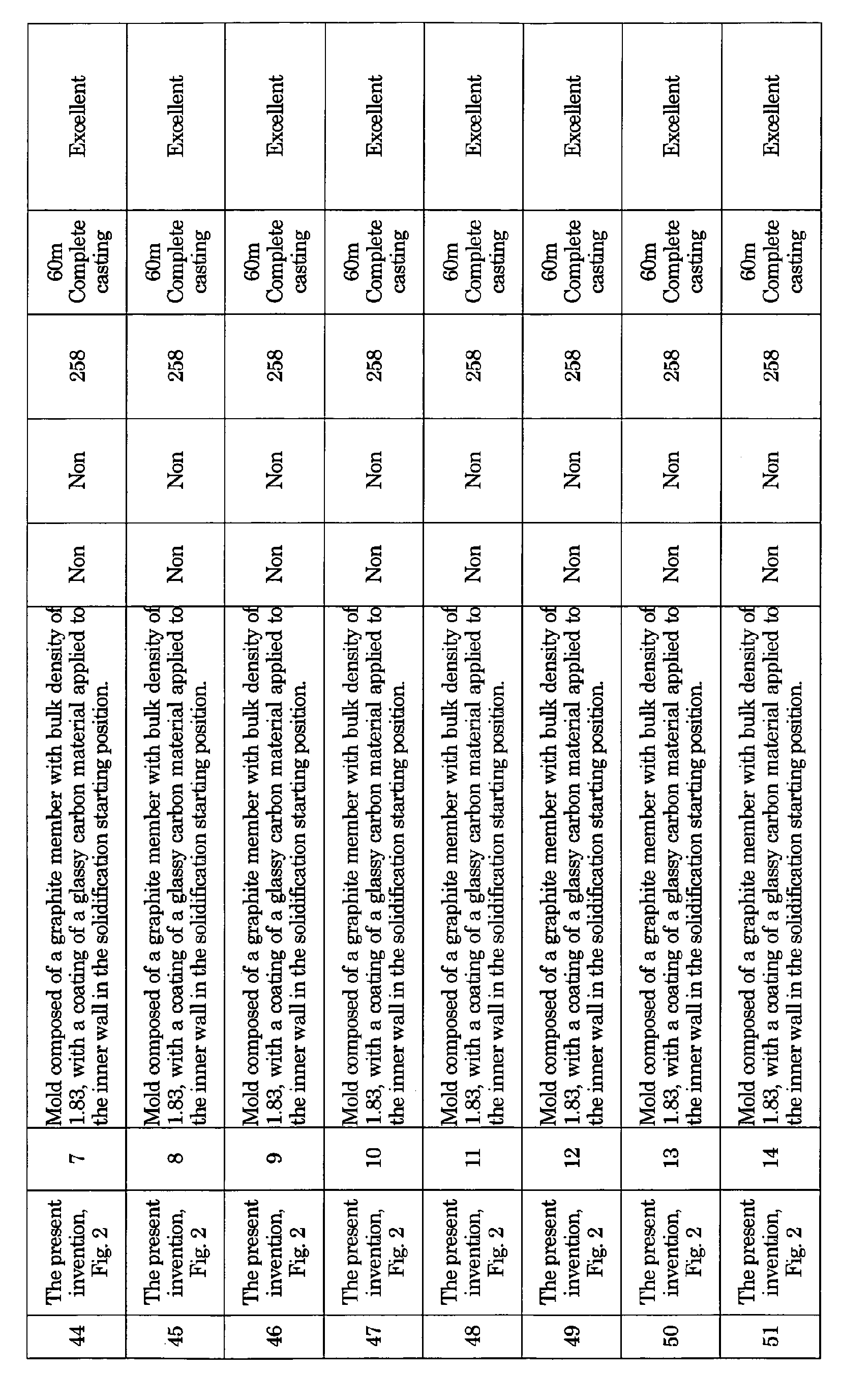

- [Table 5]
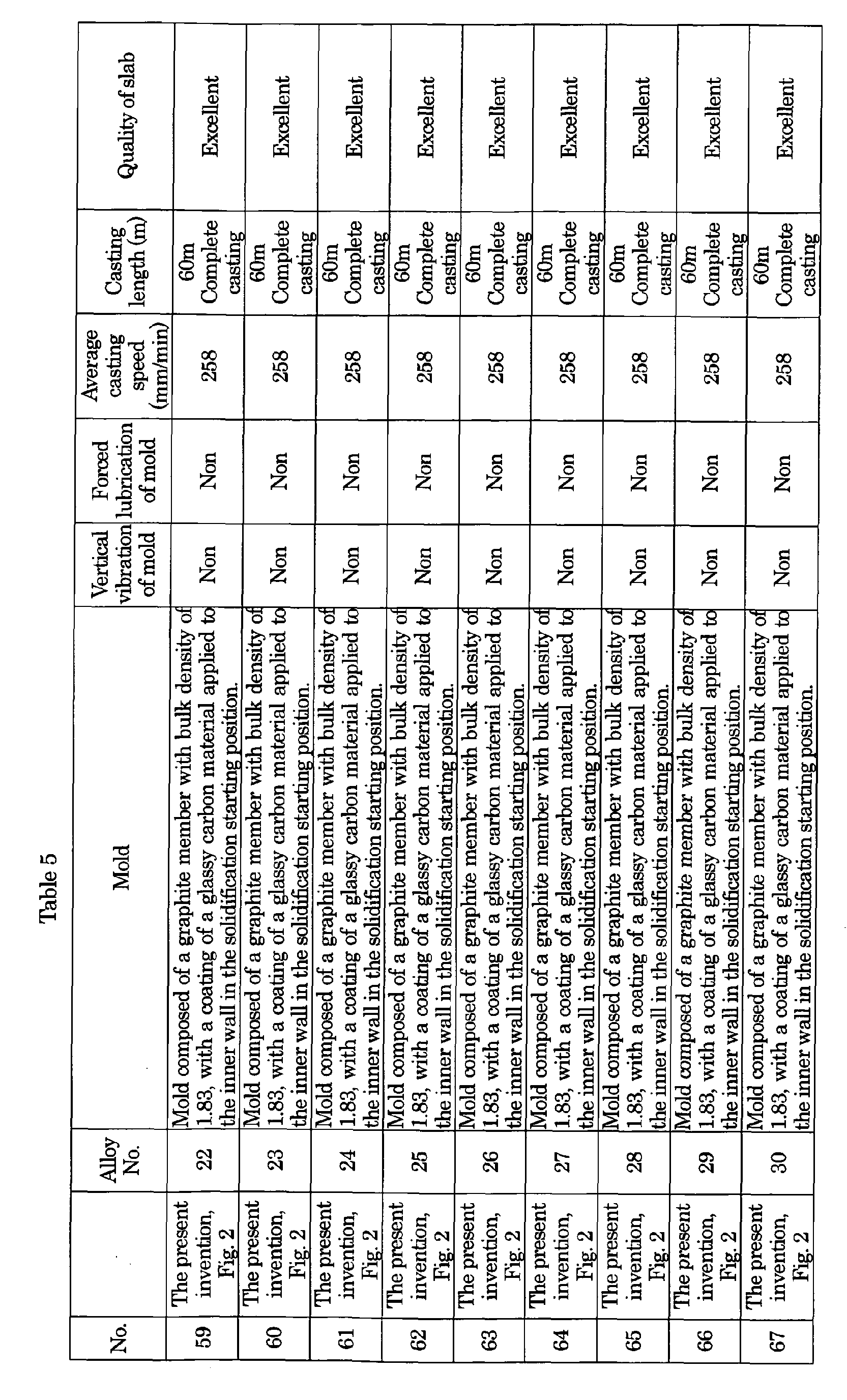


- For the three kinds of alloys shown in Table 6, slabs of 20 mm×200mm section were casted by use of a mold composed of graphite with bulk density of 1.82, with a glassy carbon applied to the inner wall, and the influence of the cooling rate on characteristics was examined by varying the water quantities of primary cooling and secondary cooling, and varying the cooling rate from the solidification start point to 600°C. The cooled slabs were cold rolled to 3 mm, then aged at 400°C for 2hr under an inert gas atmosphere followed by cold rolling to 0.5 mm, and finally aged at 350°C for 6 hr. The electric conductivity and tensile strength by tensile test of the resulting test materials were evaluated by the following methods.
- [Table 6]
Table 6 Alloy No. Ti Cr Zr Cooling rate(°C/s) TS(MPa) IACS(%) Evaluation* Remarks Comparative 35 2.00 1.51 - 0.10 - - × Not evaluated because of cracking during cold rolling The present invention 35 2.01 1.51 - 0.50 802 40 O 35 1.98 1.49 - 5.00 956 27 O 35 1.99 1.51 - 10.00 1174 19 O Comparative 36 - 1.50 2.02 0.10 420 65 × The present invention 36 - 1.50 2.04 0.50 750 52 O 36 - 1.49 1.99 5.00 872 48 O 36 - 1.48 2.00 10.00 1012 35 O Comparative 37 1.51 - 1.49 0.10 - - × Not evaluated because of cracking during cold rolling The present invention 37 1.53 - 1.50 0.50 892 35 O 37 1.49 - 1.49 5.00 1015 24 O 37 1.52 - 1.48 10.00 1230 17 O Note: * O means satisfying equation (1) - A test piece 13 B, according to the regulation of JIS Z 2201, was collected from each specimen, and the tensile strength [TS (MPa)] at room temperature (25°C) was determined according to the method regulated in JIS Z 2241.
- A test piece with width of 10mm × length of 60 mm was prepared from each specimen, current was carried in the longitudinal direction of the test piece in order to measure the potential difference between both ends of the test piece, and the electric resistance was determined by a 4-terminal method. Successively, the electric resistance (resistivity) per unit volume was calculated from the volume of the test piece that was measured by a micrometer, and the electric conductivity [IACS (%)] was determined from its ratio to resistivity 1.72 µΩcm of a reference sample obtained by annealing polycrystalline pure copper.
- In case of having a cooling rate lower than 0.5°C/s according to the comparative, cracking was caused in cold rolling, and even if cold rolling could be performed, the balance between strength and electric conductivity was poor. On the other hand, the balance between both was satisfactory and the high tensile strength in relation with the high electric conductivity is provided according to the present invention,
- The "high tensile strength in relation with conductivity" means a state satisfying the following equation (1) (this state is hereinafter referred to as "well-balanced state of tensile strength and electric conductivity"):

wherein TS: tensile strength (MPa), IACS: electric conductivity (%), k10=658.06, k11=985.48, and k12=0.0513.
IACS means the percentage to the electric conductivity of the pure copper polycrystalline material. - Further, characteristics of the alloys shown in Table 3 were similarly evaluated in the above-mentioned casting condition while setting the
cooling rate 5°C/s from the solidification start to 600°C. The result is shown in Table 7. As a result, each alloy has the balance between strength and conductivity satisfying the above equation (1), and a satisfactory result was obtained by the present invention. - [Table 7]
Table 7 Alloy No. TS(MPa) IACS(%) 1 800 45 2 1145 25 3 967 32 4 1281 20 5 820 45 6 668 79 7 965 36 8 1279 19 9 970 40 10 1469 8 11 1286 15 12 960 33 13 1143 21 14 862 36 15 1139 20 16 1288 14 17 1145 18 18 980 28 19 1138 21 20 965 29 21 1135 19 22 1386 9 23 1140 17 24 1152 18 25 1142 16 26 972 33 27 1141 20 28 1279 15 29 992 28 30 1137 20 31 1385 14 32 1145 19 33 1002 30 34 1149 18 - The present invention involves a continuous casting mold used mainly for a direct-connection type of continuous casting, with a mold directly connected to a holding furnace, and a continuous casting method of a Cu alloy. Namely, the present invention provides a mold capable of continuously and efficiently producing a sound slab or bloom, and also a continuous casting method of a Cu alloy which ensures excellent characteristics, such as strength, electric conductivity, vending workability, impact resistance and fatigue strength of the final product after working and heat treatment. Particularly, the application of the production of the Cu alloy containing elements such as Zr, Ti, Cr, Ta and V that easily generate carbides provides a profound effect.
-
- [Fig. 1] An example of a continuous casting mold according to the present invention.
- [Fig. 2] An example of the continuous casting mold according to the present invention, which has a
coating 8 of a self-lubricant or a metal-based self-lubricating composite material applied to the mold inner wall in the solidification starting position of a Cu alloy melt. - [Fig. 3] An example of the continuous casting mold according to the present invention, which is composed of a plurality of parts of mold members.
- [Fig. 4] An example of the continuous casting mold according to the present invention, which is composed of a plurality of parts of mold members, and has a
coating 8 of a self-lubricant or metal-based self-lubricating composite material applied to the mold inner wall in the solidification starting position of an alloy melt. - [Fig.5] Another example of the continuous casting mold according to the present invention, which includes a
coating 9 of ceramic material applied to the inner wall in the position that contacts with a Cu alloy melt in order to inhibit the reaction with the melt. - [Fig. 6] Another example of the continuous casting mold according to the present invention, which has a
coating 8 of a metal-based self-lubricating composite material applied to the mold inner wall in the solidification starting position of an alloy melt, and acoating 9 of a ceramic material applied to the inner wall in the position that contacts with a Cu alloy melt in order to inhibit reaction with the melt. - [Fig.7] Another example of the continuous casting mold according to the present invention, which is composed of an upstream part of a metal member and a downstream part of a graphite member, with a
coating 8 of a metal-based self-lubricating composite material applied to the inner wall in the solidification starting position of an alloy melt, and with acoating 9 of a ceramic material applied to the inner wall in the position that contacts with a Cu alloy melt in order to inhibit the reaction with the melt. - [Fig. 8] A phase diagram of a Ti-Cr alloy.
- [Fig. 9] A phase diagram of a Zr-Cr alloy.
- [Fig. 10] A phase diagram of a Ti-Zr alloy.
-
- 1. Cu alloy melt
- 2. Holding furnace wall
- 3. Mold member
- 3. Another part of mold member
- 4 Slab
- 5. Cooling jacket
- 6. Secondary cooling
- 7. Pulling out direction
- 8. Coating to the inner wall in the solidification starting position of a Cu alloy melt
- 9. Coating to the inner wall on the position that contacts with a Cu alloy melt
- 10. Solidification starting position of a Cu alloy melt
Claims (14)
- A continuous casting mold for a Cu alloy, using any one member selected from a glassy carbon, a metal-based self-lubricating composite or a graphite with a bulk density exceeding 1.92, at least for the mold member including the solidification starting position of the Cu alloy melt.
- A continuous casting mold for a Cu alloy, composed of any one member selected from a graphite, a ceramic and a metal member or of a combination of two or more parts of members thereof, in which at least the inner wall in the solidification starting position of the Cu alloy melt is coated with a self-lubricant or a metal-based self-lubricating composite material.
- A continuous casting mold for a Cu alloy, composed of a combination of two or more parts of members selected from a self-lubricant, a metal-based self-lubricating composite, a graphite, a ceramic and a metal member, in which the self-lubricant or the metal-based self-lubricating composite member is used at least for the inner wall in the solidification starting position of the Cu alloy melt.
- A continuous casting mold for a Cu alloy, composed of a combination of two or more parts of members selected from a self-lubricant, a metal-based self-lubricating composite, a graphite, a ceramic and a metal member, in which at least the inner wall in the solidification starting position of the Cu alloy melt is coated with a self-lubricant or a metal-based self-lubricating composite material.
- The continuous casting mold for a Cu alloy according to any one of claims 1 to 4, wherein the inner wall in the position that contacts with the Cu alloy melt is coated with a ceramic material.
- A continuous casting method of a Cu alloy, comprised of performing continuous casting by a slab intermittent pulling out method by use of the mold according to any one of claims 1 to 5.
- A continuous casting method of a Cu alloy, comprised of giving, at the time of continuously casting a Cu alloy by an intermittent pulling out method, a vibration that has a frequency larger than the slab intermittent pulling out frequency by two orders or more and that has a component vertical to the pulling out direction of the slab.
- A continuous casting method of a Cu alloy, comprised of continuously supplying, at the time of the continuously casting the Cu alloy by an intermittent pulling out method, a lubricant or an anti-sticking material between the inner wall of the mold and the slab.
- A continuous casting method of a Cu alloy, comprised of giving, at the time of continuously casting the Cu alloy by an intermittent pulling out method, a vibration that has a frequency larger than the slab intermittent pulling out frequency by two orders or more and that has a component vertical to the pulling out direction to a mold, and continuously supplying a lubricant or an anti-sticking material between the inner wall of the mold and the slab.
- The continuous casting method of a Cu alloy according to claim 6, comprised of giving, at the time of continuously casting the Cu alloy by an intermittent pulling out method, a vibration that has a frequency larger than the intermittent pulling out frequency by two orders or more and that has a component vertical to the pulling out direction of the slab.
- The continuous casting method of a Cu alloy according to claim 6 or 10, comprised of continuously supplying, at the time of continuously casting the Cu alloy by an intermittent pulling out method, a lubricant or an anti-sticking material between the inner wall of the mold and the slab.
- The continuous casting method of a Cu alloy according to any one of claims 6 to 11, wherein the Cu alloy contains, by mass %, one or more components selected from Cr: 0.01 to 5%, Ti: 0.01 to 5%, Zr: 0.01 to 5%, Nb: 0.01 to 5%, Ta: 0.01 to 5%, Al: 0.01 to 5%, Mo: 0.01 to 5%, V: 0.01 to 5%, Co: 0.01 to 5%, Mn: 0.01 to 5%, Si: 0.01 to 5%, Be: 0.01 to 5%, and Hf: 0.01 to 5%.
- The continuous casting method of a Cu alloy according to claim 12, wherein the Cu alloy further contains, by mass%, 0.001 to 5 % in total of one or more of the alloy components selected from at least one group of the following three groups:First group: 0.001 to 1 mass% in total of one or more selected from P, B, Sb, Bi, Pb, Cd, S and As;Second group: 0.01 to 5 mass% in total of one or more selected from Sn, Ag, Zn, Ni, Au, Pd, Fe, W, In and Ge; andThird group: 0.01 to 3 mass% in total of one or more selected from Te, Se, Sr, T1, Rb, Cs, Ba, Re, Os, Rh, Po, Ga, Tc, Ru, Pd, Ir, Pt and Ta.
- The continuous casting method of a Cu alloy according to claim 12 or 13, wherein the Cu alloy further contains, by mass %, 0.001 to 2% in total of one or more of alloy components selected from Li, Ca, Mg and rare earth elements.
Applications Claiming Priority (4)
| Application Number | Priority Date | Filing Date | Title |
|---|---|---|---|
| JP2003331909 | 2003-09-24 | ||
| JP2004097223 | 2004-03-29 | ||
| JP2004234641 | 2004-08-11 | ||
| PCT/JP2004/013756 WO2005028143A1 (en) | 2003-09-24 | 2004-09-21 | Continuous casting mold and method of continuous casting for copper alloy |
Publications (2)
| Publication Number | Publication Date |
|---|---|
| EP1688198A1 true EP1688198A1 (en) | 2006-08-09 |
| EP1688198A4 EP1688198A4 (en) | 2007-03-21 |
Family
ID=34381782
Family Applications (1)
| Application Number | Title | Priority Date | Filing Date |
|---|---|---|---|
| EP04787939A Withdrawn EP1688198A4 (en) | 2003-09-24 | 2004-09-21 | CASTING MOLD AND CONTINUOUS CASTING METHOD FOR COPPER ALLOY |
Country Status (5)
| Country | Link |
|---|---|
| US (1) | US20060180293A1 (en) |
| EP (1) | EP1688198A4 (en) |
| JP (1) | JP4333881B2 (en) |
| TW (1) | TWI272145B (en) |
| WO (1) | WO2005028143A1 (en) |
Cited By (12)
| Publication number | Priority date | Publication date | Assignee | Title |
|---|---|---|---|---|
| CN102634688A (en) * | 2011-02-10 | 2012-08-15 | 湖南特力新材料有限公司 | Leadless free-cutting copper alloy and preparation method |
| CN103114218A (en) * | 2013-03-11 | 2013-05-22 | 武汉大学 | Preparation method of copper-chrome alloy |
| RU2510420C2 (en) * | 2009-09-07 | 2014-03-27 | Сирогане Ко., Лтд. | Copper alloy and method of its production |
| CN104046832A (en) * | 2014-06-05 | 2014-09-17 | 锐展(铜陵)科技有限公司 | Making method of highly conductive copper alloy wire or automobile generator |
| CN104046831A (en) * | 2014-06-05 | 2014-09-17 | 锐展(铜陵)科技有限公司 | Making method of copper alloy wire for automobiles |
| CN104588618A (en) * | 2014-11-28 | 2015-05-06 | 太原科技大学 | Continuous casting device and continuous casting method of magnesium alloy composite board |
| CN104630546A (en) * | 2015-03-05 | 2015-05-20 | 苏州市凯业金属制品有限公司 | High-strength heat-resistant copper alloy metal tube |
| CN104928523A (en) * | 2015-07-10 | 2015-09-23 | 苏州科茂电子材料科技有限公司 | Copper alloy lead material for communication cable and preparing method thereof |
| CN110396621A (en) * | 2019-08-27 | 2019-11-01 | 天长市华海电子科技有限公司 | A kind of anti intercrystalline corrosion forge piece and preparation method thereof |
| CN111850345A (en) * | 2020-07-23 | 2020-10-30 | 唐山中科量子激光科技有限公司 | Wear-resistant high-temperature-erosion-resistant alloy material, crystallizer copper plate surface treatment method and crystallizer copper plate |
| CN116117084A (en) * | 2022-12-16 | 2023-05-16 | 攀钢集团攀枝花钢铁研究院有限公司 | Preparation method of high-strength high-toughness cold-working die steel billet |
| RU2811355C1 (en) * | 2023-06-26 | 2024-01-11 | федеральное государственное автономное образовательное учреждение высшего образования "Пермский национальный исследовательский политехнический университет" | Method for producing composite material based on copper powder |
Families Citing this family (43)
| Publication number | Priority date | Publication date | Assignee | Title |
|---|---|---|---|---|
| DE102006015282A1 (en) * | 2006-04-01 | 2007-10-04 | Honeywell Technologies Sarl Ecc | Bronze casting mold with thermal insulation lining and casting process for manufacture of drinking water valve housing and fittings |
| ATE539823T1 (en) * | 2008-03-05 | 2012-01-15 | Southwire Co | ULTRASONIC PROBE WITH NIOBIUM PROTECTIVE LAYER |
| JP5208556B2 (en) * | 2008-03-31 | 2013-06-12 | Jx日鉱日石金属株式会社 | Titanium copper suitable for precision press working and method for producing the titanium copper |
| JP5873618B2 (en) * | 2009-08-18 | 2016-03-01 | 新日鐵住金株式会社 | Method for producing copper alloy |
| US8652397B2 (en) | 2010-04-09 | 2014-02-18 | Southwire Company | Ultrasonic device with integrated gas delivery system |
| US8574336B2 (en) | 2010-04-09 | 2013-11-05 | Southwire Company | Ultrasonic degassing of molten metals |
| CN102476177B (en) * | 2010-11-29 | 2013-05-29 | 株洲南方有色焊材有限公司 | Upward drawing method for copper alloy wire blank |
| JP5802150B2 (en) * | 2012-02-24 | 2015-10-28 | 株式会社神戸製鋼所 | Copper alloy |
| JP6001420B2 (en) * | 2012-11-07 | 2016-10-05 | 株式会社フジクラ | Cu-Mg alloy body, Cu-Mg alloy body manufacturing method, and wire drawing material manufacturing method |
| CN103114222B (en) * | 2013-03-14 | 2014-10-22 | 上海天申铜业集团有限公司 | Casting method of lead-free water meter case |
| JP6674376B2 (en) | 2013-11-18 | 2020-04-01 | サウスワイヤー・カンパニー・リミテッド・ライアビリティ・カンパニーSouthwire Company,Llc | Ultrasonic probe with exhaust port for degassing molten metal |
| CN103695697B (en) * | 2013-12-03 | 2016-04-20 | 江苏帕齐尼铜业有限公司 | A kind of chromiumcopper and preparation method thereof |
| CN104051076A (en) * | 2014-06-05 | 2014-09-17 | 锐展(铜陵)科技有限公司 | Method for preparing low-expansion copper alloy wire used for automotive cables and cords |
| CN104046838A (en) * | 2014-06-05 | 2014-09-17 | 锐展(铜陵)科技有限公司 | Preparation method of high-strength high-toughness copper alloy wire for automatic cables |
| CN104152728A (en) * | 2014-06-05 | 2014-11-19 | 锐展(铜陵)科技有限公司 | Preparation method of high heat-conducting copper alloy wire for automobile wire harness |
| CN104046842A (en) * | 2014-06-05 | 2014-09-17 | 锐展(铜陵)科技有限公司 | Preparation method of high-content nickel-copper alloy wire for electronic instrument of automobile |
| CN104046837A (en) * | 2014-06-05 | 2014-09-17 | 锐展(铜陵)科技有限公司 | Making method of leadless copper alloy wire for automobile industry |
| JP6488951B2 (en) * | 2014-09-25 | 2019-03-27 | 三菱マテリアル株式会社 | Mold material for casting and Cu-Cr-Zr alloy material |
| CN104475468B (en) * | 2014-12-09 | 2016-08-24 | 中色(天津)特种材料有限公司 | N6 nickel alloy wire continuous casting even pulls out processing technique |
| JP6228941B2 (en) * | 2015-01-09 | 2017-11-08 | Jx金属株式会社 | Titanium copper with plating layer |
| CN104928528A (en) * | 2015-07-06 | 2015-09-23 | 苏州科茂电子材料科技有限公司 | Conductive copper alloy material and preparing method thereof |
| US10233515B1 (en) | 2015-08-14 | 2019-03-19 | Southwire Company, Llc | Metal treatment station for use with ultrasonic degassing system |
| CN105108079A (en) * | 2015-09-24 | 2015-12-02 | 云南新铜人实业有限公司 | Horizontal continuous casting copper belt production process |
| WO2017170699A1 (en) | 2016-03-30 | 2017-10-05 | 三菱マテリアル株式会社 | Copper alloy for electronic and electrical equipment, copper alloy plate strip for electronic and electrical equipment, component for electronic and electrical equipment, terminal, busbar, and movable piece for relays |
| JP6226098B2 (en) * | 2016-03-30 | 2017-11-08 | 三菱マテリアル株式会社 | Copper alloy for electronic and electrical equipment, copper alloy sheet material for electronic and electrical equipment, electronic and electrical equipment parts, terminals, bus bars, and movable pieces for relays |
| FI3438299T3 (en) | 2016-03-30 | 2023-05-23 | Mitsubishi Materials Corp | Copper alloy plate strip for electronic and electrical equipment, component, terminal, busbar and movable piece for relays |
| CN106111931B (en) * | 2016-06-28 | 2018-06-05 | 北京科技大学 | A kind of metal clad material solid-liquid continuous casting composite forming apparatus and process |
| CN106424613A (en) * | 2016-11-29 | 2017-02-22 | 郑州中拓知识产权代理有限公司 | Copper rod continuous casting machine |
| KR101830841B1 (en) | 2016-11-29 | 2018-02-22 | 한국생산기술연구원 | Copper alloys having high wear resistant for synchronizer ring and manufacturing method thereof |
| CN106735003B (en) * | 2016-12-08 | 2018-09-28 | 北京科技大学 | A kind of non-vacuum melting horizontal casting production technology of high-strength highly-conductive Cu-Cr-Zr alloy bar materials |
| CN106583672B (en) * | 2016-12-09 | 2018-09-25 | 北京科技大学 | A kind of copper chromium alloy horizontal continuous casting process |
| CN107511469A (en) * | 2017-10-13 | 2017-12-26 | 安阳恒安电机有限公司 | A kind of squirrel cage motor rotor low pressure cast copper equipment, cast copper and its cast copper method |
| CN111788320B (en) | 2018-03-30 | 2022-01-14 | 三菱综合材料株式会社 | Copper alloy for electronic and electrical equipment, copper alloy strip for electronic and electrical equipment, module for electronic and electrical equipment, terminal, and bus bar |
| JP6780187B2 (en) | 2018-03-30 | 2020-11-04 | 三菱マテリアル株式会社 | Copper alloys for electronic / electrical equipment, copper alloy strips for electronic / electrical equipment, parts for electronic / electrical equipment, terminals, and busbars |
| CN113458352B (en) * | 2020-03-30 | 2023-11-24 | 日本碍子株式会社 | Method for producing Cu-Ni-Sn alloy and cooler for use in same |
| CN112355263A (en) * | 2020-10-14 | 2021-02-12 | 刘珍 | Semi-solid forming device for aluminum alloy processing |
| JP7433263B2 (en) * | 2021-03-03 | 2024-02-19 | 日本碍子株式会社 | Manufacturing method of Cu-Ni-Sn alloy |
| JP7735699B2 (en) * | 2021-07-13 | 2025-09-09 | 株式会社レゾナック | Horizontal continuous casting equipment, method for manufacturing aluminum alloy cast rods |
| CN113680980B (en) * | 2021-09-06 | 2022-12-09 | 西安斯瑞先进铜合金科技有限公司 | Production process for horizontally continuously casting copper-manganese alloy |
| CN114012052B (en) * | 2021-12-30 | 2022-05-03 | 东北大学 | Horizontal continuous casting equipment for aluminum alloy cast ingot |
| CN115475830A (en) * | 2022-09-14 | 2022-12-16 | 南京航空航天大学 | Short-process preparation and processing method of high-temperature alloy pipe |
| CN115786752B (en) * | 2022-11-24 | 2024-05-31 | 有研工程技术研究院有限公司 | Method for improving corrosion resistance of cupronickel alloy pipe |
| CN115852201A (en) * | 2022-12-28 | 2023-03-28 | 北冶功能材料(江苏)有限公司 | A kind of production method of copper-nickel-tin alloy ingot |
Family Cites Families (18)
| Publication number | Priority date | Publication date | Assignee | Title |
|---|---|---|---|---|
| US3424228A (en) * | 1966-04-08 | 1969-01-28 | Ducommun Inc | Anisotropic mold liner for continuous casting of metals |
| US3435881A (en) * | 1967-01-03 | 1969-04-01 | Carbone Corp | Anisotropic continuous casting mold |
| DE2634633C2 (en) * | 1976-07-31 | 1984-07-05 | Kabel- und Metallwerke Gutehoffnungshütte AG, 3000 Hannover | Continuous casting mold made of a copper material, especially for continuous casting of steel |
| DE2657207C2 (en) * | 1976-12-17 | 1978-10-05 | Kreidler Werke Gmbh, 7000 Stuttgart | Process for the continuous casting of metal alloys, in particular brass alloys and continuous casting mold for carrying out the process |
| JPS5785652A (en) * | 1980-11-19 | 1982-05-28 | Kawasaki Steel Corp | Continuous casting method for hollow blank material for pipe making |
| JPS6058783B2 (en) * | 1982-01-20 | 1985-12-21 | 日本鉱業株式会社 | Method for manufacturing copper alloy for lead material of semiconductor equipment |
| JPS59133942A (en) * | 1983-01-21 | 1984-08-01 | Kobe Steel Ltd | Inside surface treatment of mold for horizontal continuous casting |
| JPS61169149A (en) * | 1985-01-22 | 1986-07-30 | Nippon Mining Co Ltd | Continuous casting method |
| US5171491A (en) * | 1986-02-04 | 1992-12-15 | The Carborundum Company | Method of producing near net shape fused cast refractories |
| JPH026037A (en) * | 1988-06-27 | 1990-01-10 | Nkk Corp | Continuous steel casting method |
| JPH03155436A (en) * | 1989-11-10 | 1991-07-03 | Sumitomo Light Metal Ind Ltd | Horizontal continuous casting method |
| JPH03210942A (en) * | 1990-01-11 | 1991-09-13 | Sumitomo Metal Ind Ltd | Method for continuously casting steel |
| JP3013461B2 (en) * | 1991-02-22 | 2000-02-28 | 日立電線株式会社 | Continuous casting mold |
| JPH05318034A (en) * | 1992-05-22 | 1993-12-03 | Furukawa Electric Co Ltd:The | Complex graphite mold for continuous casting |
| JPH06179930A (en) * | 1992-08-25 | 1994-06-28 | Tatsuta Electric Wire & Cable Co Ltd | Graphite-made crucible or mold |
| JPH09141394A (en) * | 1995-11-17 | 1997-06-03 | Sumitomo Metal Ind Ltd | Continuous casting mold and method of manufacturing and using the same |
| JP3504129B2 (en) * | 1997-11-13 | 2004-03-08 | 東海カーボン株式会社 | Graphite mold for copper alloy continuous casting |
| CH695210A5 (en) * | 2000-12-11 | 2006-01-31 | Concast Ag | Mold for the continuous casting of molten steel. |
-
2004
- 2004-09-21 EP EP04787939A patent/EP1688198A4/en not_active Withdrawn
- 2004-09-21 JP JP2005514086A patent/JP4333881B2/en not_active Expired - Fee Related
- 2004-09-21 WO PCT/JP2004/013756 patent/WO2005028143A1/en not_active Ceased
- 2004-09-23 TW TW093128891A patent/TWI272145B/en not_active IP Right Cessation
-
2006
- 2006-03-23 US US11/386,924 patent/US20060180293A1/en not_active Abandoned
Cited By (14)
| Publication number | Priority date | Publication date | Assignee | Title |
|---|---|---|---|---|
| RU2510420C2 (en) * | 2009-09-07 | 2014-03-27 | Сирогане Ко., Лтд. | Copper alloy and method of its production |
| CN102634688A (en) * | 2011-02-10 | 2012-08-15 | 湖南特力新材料有限公司 | Leadless free-cutting copper alloy and preparation method |
| CN102634688B (en) * | 2011-02-10 | 2014-05-07 | 湖南特力新材料有限公司 | Leadless free-cutting copper alloy and preparation method |
| CN103114218A (en) * | 2013-03-11 | 2013-05-22 | 武汉大学 | Preparation method of copper-chrome alloy |
| CN104046832A (en) * | 2014-06-05 | 2014-09-17 | 锐展(铜陵)科技有限公司 | Making method of highly conductive copper alloy wire or automobile generator |
| CN104046831A (en) * | 2014-06-05 | 2014-09-17 | 锐展(铜陵)科技有限公司 | Making method of copper alloy wire for automobiles |
| CN104588618A (en) * | 2014-11-28 | 2015-05-06 | 太原科技大学 | Continuous casting device and continuous casting method of magnesium alloy composite board |
| CN104630546A (en) * | 2015-03-05 | 2015-05-20 | 苏州市凯业金属制品有限公司 | High-strength heat-resistant copper alloy metal tube |
| CN104928523A (en) * | 2015-07-10 | 2015-09-23 | 苏州科茂电子材料科技有限公司 | Copper alloy lead material for communication cable and preparing method thereof |
| CN110396621A (en) * | 2019-08-27 | 2019-11-01 | 天长市华海电子科技有限公司 | A kind of anti intercrystalline corrosion forge piece and preparation method thereof |
| CN111850345A (en) * | 2020-07-23 | 2020-10-30 | 唐山中科量子激光科技有限公司 | Wear-resistant high-temperature-erosion-resistant alloy material, crystallizer copper plate surface treatment method and crystallizer copper plate |
| CN111850345B (en) * | 2020-07-23 | 2021-06-18 | 唐山中科量子激光科技有限公司 | Wear-resistant high-temperature-erosion-resistant alloy material, crystallizer copper plate surface treatment method and crystallizer copper plate |
| CN116117084A (en) * | 2022-12-16 | 2023-05-16 | 攀钢集团攀枝花钢铁研究院有限公司 | Preparation method of high-strength high-toughness cold-working die steel billet |
| RU2811355C1 (en) * | 2023-06-26 | 2024-01-11 | федеральное государственное автономное образовательное учреждение высшего образования "Пермский национальный исследовательский политехнический университет" | Method for producing composite material based on copper powder |
Also Published As
| Publication number | Publication date |
|---|---|
| TW200528213A (en) | 2005-09-01 |
| JPWO2005028143A1 (en) | 2007-11-15 |
| WO2005028143A1 (en) | 2005-03-31 |
| JP4333881B2 (en) | 2009-09-16 |
| EP1688198A4 (en) | 2007-03-21 |
| TWI272145B (en) | 2007-02-01 |
| US20060180293A1 (en) | 2006-08-17 |
Similar Documents
| Publication | Publication Date | Title |
|---|---|---|
| EP1688198A1 (en) | Continuous casting mold and method of continuous casting for copper alloy | |
| KR100766639B1 (en) | Copper alloy and method for production thereof | |
| KR100985310B1 (en) | Manufacturing method of magnesium alloy material | |
| EP1731624A1 (en) | Copper alloy and method for production thereof | |
| EP3173498A1 (en) | Alloy structure and method for producing alloy structure | |
| JP5525813B2 (en) | Thermal spray coated work roll | |
| EP3173499A1 (en) | Alloy structure and method for manufacturing alloy structure | |
| WO2004070070A1 (en) | Cu ALLOY AND METHOD FOR PRODUCTION THEREOF | |
| JP2004353011A (en) | Electrode material and its manufacturing method | |
| WO2006109801A1 (en) | Copper alloy and process for producing the same | |
| WO2006104152A1 (en) | Copper alloy and process for producing the same | |
| JPWO2005072891A1 (en) | Copper alloy continuous casting method | |
| JP2688729B2 (en) | Aluminum corrosion resistant material | |
| JP4796994B2 (en) | Method for producing molten aluminum erodible cast iron and molten aluminum erodible cast iron | |
| JPS5874572A (en) | Plasticity working tool for copper and copper alloy | |
| JPH0671406A (en) | Injection sleeve for die casting and method for casting aluminum or aluminum alloy member | |
| JPH0873286A (en) | Silicon nitride sintered compact and its production and member for molten metal using the same | |
| JP3396800B2 (en) | Composite sintered alloy for non-ferrous metal melt and method for producing the same | |
| JP4694227B2 (en) | Continuous casting mold | |
| Bazin et al. | 5/6 Scores d’évaluation de la sédation et de l’analgésie | |
| JP2023144716A (en) | Casting mold for continuous casting | |
| JPH0848586A (en) | Laminated ceramic sintered compact and member for molten iron-based alloy | |
| JP2724418B2 (en) | High-strength sealing alloy with excellent Ag braze flowability and method for producing the same | |
| JPS5943858A (en) | Surface hardened cu alloy member with superior wear resistance at high temperature | |
| Corti et al. | Continuous Casting of Jewelry Alloys |
Legal Events
| Date | Code | Title | Description |
|---|---|---|---|
| PUAI | Public reference made under article 153(3) epc to a published international application that has entered the european phase |
Free format text: ORIGINAL CODE: 0009012 |
|
| 17P | Request for examination filed |
Effective date: 20060301 |
|
| AK | Designated contracting states |
Kind code of ref document: A1 Designated state(s): AT BE BG CH CY CZ DE DK EE ES FI FR GB GR HU IE IT LI LU MC NL PL PT RO SE SI SK TR |
|
| DAX | Request for extension of the european patent (deleted) | ||
| A4 | Supplementary search report drawn up and despatched |
Effective date: 20070219 |
|
| RIC1 | Information provided on ipc code assigned before grant |
Ipc: B22D 11/14 20060101ALI20070213BHEP Ipc: B22D 11/00 20060101ALI20070213BHEP Ipc: B22D 11/059 20060101AFI20070213BHEP Ipc: B22D 11/07 20060101ALI20070213BHEP |
|
| 17Q | First examination report despatched |
Effective date: 20070928 |
|
| RAP1 | Party data changed (applicant data changed or rights of an application transferred) |
Owner name: MATERIALS SOLUTION INC. |
|
| STAA | Information on the status of an ep patent application or granted ep patent |
Free format text: STATUS: THE APPLICATION IS DEEMED TO BE WITHDRAWN |
|
| 18D | Application deemed to be withdrawn |
Effective date: 20080409 |