WO2005028143A1 - Continuous casting mold and method of continuous casting for copper alloy - Google Patents
Continuous casting mold and method of continuous casting for copper alloy Download PDFInfo
- Publication number
- WO2005028143A1 WO2005028143A1 PCT/JP2004/013756 JP2004013756W WO2005028143A1 WO 2005028143 A1 WO2005028143 A1 WO 2005028143A1 JP 2004013756 W JP2004013756 W JP 2004013756W WO 2005028143 A1 WO2005028143 A1 WO 2005028143A1
- Authority
- WO
- WIPO (PCT)
- Prior art keywords
- alloy
- mold
- metal
- piece
- self
- Prior art date
Links
Classifications
-
- B—PERFORMING OPERATIONS; TRANSPORTING
- B22—CASTING; POWDER METALLURGY
- B22D—CASTING OF METALS; CASTING OF OTHER SUBSTANCES BY THE SAME PROCESSES OR DEVICES
- B22D11/00—Continuous casting of metals, i.e. casting in indefinite lengths
- B22D11/14—Plants for continuous casting
- B22D11/143—Plants for continuous casting for horizontal casting
-
- B—PERFORMING OPERATIONS; TRANSPORTING
- B22—CASTING; POWDER METALLURGY
- B22D—CASTING OF METALS; CASTING OF OTHER SUBSTANCES BY THE SAME PROCESSES OR DEVICES
- B22D11/00—Continuous casting of metals, i.e. casting in indefinite lengths
- B22D11/001—Continuous casting of metals, i.e. casting in indefinite lengths of specific alloys
- B22D11/004—Copper alloys
-
- B—PERFORMING OPERATIONS; TRANSPORTING
- B22—CASTING; POWDER METALLURGY
- B22D—CASTING OF METALS; CASTING OF OTHER SUBSTANCES BY THE SAME PROCESSES OR DEVICES
- B22D11/00—Continuous casting of metals, i.e. casting in indefinite lengths
- B22D11/04—Continuous casting of metals, i.e. casting in indefinite lengths into open-ended moulds
- B22D11/059—Mould materials or platings
-
- B—PERFORMING OPERATIONS; TRANSPORTING
- B22—CASTING; POWDER METALLURGY
- B22D—CASTING OF METALS; CASTING OF OTHER SUBSTANCES BY THE SAME PROCESSES OR DEVICES
- B22D11/00—Continuous casting of metals, i.e. casting in indefinite lengths
- B22D11/12—Accessories for subsequent treating or working cast stock in situ
-
- C—CHEMISTRY; METALLURGY
- C22—METALLURGY; FERROUS OR NON-FERROUS ALLOYS; TREATMENT OF ALLOYS OR NON-FERROUS METALS
- C22C—ALLOYS
- C22C9/00—Alloys based on copper
-
- C—CHEMISTRY; METALLURGY
- C22—METALLURGY; FERROUS OR NON-FERROUS ALLOYS; TREATMENT OF ALLOYS OR NON-FERROUS METALS
- C22C—ALLOYS
- C22C9/00—Alloys based on copper
- C22C9/02—Alloys based on copper with tin as the next major constituent
-
- C—CHEMISTRY; METALLURGY
- C22—METALLURGY; FERROUS OR NON-FERROUS ALLOYS; TREATMENT OF ALLOYS OR NON-FERROUS METALS
- C22C—ALLOYS
- C22C9/00—Alloys based on copper
- C22C9/04—Alloys based on copper with zinc as the next major constituent
-
- C—CHEMISTRY; METALLURGY
- C22—METALLURGY; FERROUS OR NON-FERROUS ALLOYS; TREATMENT OF ALLOYS OR NON-FERROUS METALS
- C22C—ALLOYS
- C22C9/00—Alloys based on copper
- C22C9/10—Alloys based on copper with silicon as the next major constituent
Definitions
- the present invention relates to a continuous manufacturing method and a continuous manufacturing method for a Cu alloy.
- the present invention relates to a ⁇ type used in a direct connection type continuous forming machine in which a holding furnace is directly connected to a ⁇ type, and a continuous manufacturing method of a Cu alloy using the ⁇ type.
- the IT boom has been used in electrical and electronic components such as lead frames, terminals, connectors, springs, and contact elements in the movement of electrical equipment for mobile phones, personal computers, and automobiles.
- the performance of Cu alloys is becoming increasingly important. Typical required characteristics are firstly high strength for light weight dangling, and secondly, high conductivity dangling for suppressing an increase in electric resistance due to a decrease in cross-sectional area due to light weight dangling. .
- improvement of workability such as bending work accompanying downsizing of parts, improvement of heat resistance to withstand use even in relatively harsh environments, and improvement of fatigue resistance. Has become.
- Such a high-strength and highly-conductive material is used in an environment such as an ammunition warehouse or a coal mine where excellent spark generation resistance is required in addition to the performance required for conventional tools such as wear resistance. It can also be applied to safety tool materials used below.
- a material for example, there is an example of a Cu alloy in Patent Document 1.
- the first method is a direct connection type continuous structure (a horizontal type, a vertical type, or the like) using a graphite mold directly connected to a holding furnace.
- a graphite material having a self-lubricating property and a high thermal conductivity and a bulk density of 1.7 to 1.9 is generally used as a ⁇ -type material.
- This method achieves a high V ⁇ cooling rate in the cooling process after solidification, and has a small thickness that reaches the final product without going through the subsequent solution treatment and hot working! Suitable for getting pieces! /
- Cu is supplied through a nozzle immersed in a molten metal pool described in Patent Document 1. It is a non-direct connection type continuous structure (a vertical type, a curved type, a vertical curved type, etc.) that pours into a mold made of a metal material or an alloy material typified by a Cu alloy.
- the nozzle thickness is limited to a relatively large one of about 100 mm or more because the nozzle is immersed in the molten metal pool in the mold. Since this method has a low cooling rate in the cooling process after solidification, a hot process such as solution treatment or hot working is indispensable until a final product is obtained.
- an appropriate method is selected according to the required alloy composition, the piece cross-sectional shape, the cooling rate, and the like.
- the former direct connection type
- a large cross section size piece is used.
- non-coupling type is often used when Cu alloy is required or when the Cu alloy contains an element that is highly reactive with C in the Dalaphite material.
- Patent Document 1 JP-A-61-250134
- a first object of the present invention is to provide a continuous forming mold suitable for a direct-coupled continuous forming of a Cu alloy containing an alloy element that easily reacts with C such as Zr, Ti, and Cr.
- a second object of the present invention is to provide a continuous method for producing a Cu alloy using the mold. It should be noted that the continuous structure in the present invention has a great effect also on the continuous structure of a material other than the Cu alloy, particularly a non-ferrous metal material.
- New aiming for higher strength and higher conductivity! / ⁇ Cu alloys contain elements that react easily with C, such as Zr, Ti, and Cr. In addition, a high cooling rate is required in the cooling process after solidification to achieve good properties. However, it was found that these alloys had the following problems caused by the reaction between C in the graphite material, which is a ⁇ -type material, and the above elements.
- the present invention has been made to solve these problems and suppresses seizure of an initially formed solidified shell to a mold, and is sufficiently high in a cooling process after solidification!
- the present invention relates to a continuous production mold capable of obtaining a cooling rate and a continuous production method using the same, and the invention of the following continuous production mold (1)-(5) and the continuous production method (6) — The invention of (14).
- These inventions may be collectively referred to as the present invention.
- a glassy carbon material, a metal-based self-lubricating composite material, or a graphite material having a bulk density of more than 1.92 is used for at least the ⁇ -shaped portion facing the solidification start position of the molten Cu alloy.
- the continuous production type for Cu alloy is used for at least the ⁇ -shaped portion facing the solidification start position of the molten Cu alloy.
- At least one of a graphite member a single member selected from a graphite material member, a ceramic material member, and a metal material member, or a combination of two or more members.
- a continuous production mold for Cu alloys characterized in that the internal wall of the copper mold facing the solidification start position of the molten Cu alloy is coated with a self-lubricating material or a metal-based self-lubricating composite material.
- a self-lubricating material member or a metal-based self-lubricating composite material member is used as an inner wall member of at least a shape corresponding to at least the solidification start position of the molten Cu alloy. , Continuous fabrication type for Cu alloy.
- Continuous fabrication type for Cu alloy
- a continuous manufacturing method for a Cu alloy comprising applying vibration having a component to a mold.
- the cycle number is at least two orders of magnitude greater than the number of intermittent drawing cycles of the piece, and is perpendicular to the drawing direction.
- a continuous production method of Cu alloy comprising: applying vibration having a component to a mold; and continuously supplying a lubricant or an anti-seizure agent between an inner wall of the mold and the piece.
- the number of cycles is at least two orders of magnitude larger than the number of intermittent drawing cycles of the piece and is perpendicular to the drawing direction.
- (6) The method for continuous production of a Cu alloy according to the above (6), wherein vibration having various components is applied to the mold.
- Cu alloy force Further, in mass%, at least one of the following first group forces up to the third group: (12) The continuous production method for a Cu alloy according to the above (12), wherein one or more selected alloy components are contained in a total amount of 0.001 to 5% by mass.
- Group 1 One or more selected from among P, B, Sb, Bi, Pb, Cd, S and As 0.001-1% by mass in total
- Group 2 One, two or more selected from Sn, Ag, Zn, Ni, Au, Pd, Fe, W, In, and Ge 0.01-5% by mass in total
- Group 3 One or two selected from Te, Se, Sr, Tl, Rb, Cs, Ba, Re, Os, Rh, Po, Ga, Tc, Ru, Pd, Ir, Pt and Ta Above total 0.01-3% by mass
- the present invention it is possible to provide a continuous structure mold capable of continuously producing sound pieces efficiently and stably. Further, it is possible to provide a method for continuously producing a Cu alloy, which is excellent in properties of a final product after processing and heat treatment, for example, strength, conductivity, or fatigue strength. In particular, a great effect can be obtained when applied to the structure of a Cu alloy containing Zr, Ti, Cr, Ta, V, etc., which are elements that easily form carbides. In addition, the present invention has a great effect on materials other than Cu alloys, especially non-ferrous metal materials.
- FIGS. 1 to 7 show an example of a direct connection type horizontal continuous structure according to the present invention.
- the type III is directly connected to the refractory of the holding furnace wall 2 that contains the molten metal 1 of the Cu alloy.
- a connection refractory such as a feed nozzle may be provided between the holding furnace wall and the mold.
- a cooling chamber 1 having a structure for flowing cooling water etc. inside the mold is placed in close contact with the outside of the member 3 constituting the The heat is removed by primary cooling of the molten metal and solidification proceeds to form piece 4.
- the piece 4 can be water jet, air jet or air-water mixed. Secondary cooling 6 is performed by joint injection and the like. The piece 4 is withdrawn in the withdrawal direction 7.
- the mold according to the present invention includes a coating 8 on the inner wall of the mold corresponding to the solidification start position 10 of the Cu alloy melt and a mold of the mold corresponding to the Z or the Cu alloy melt upstream of the solidification start position. Some have an inner wall coating 9.
- the ⁇ shape may include a plurality of members. That is, the ⁇ shape may be configured by the member 3 forming the ⁇ shape and the other member 3 ′ forming the ⁇ shape.
- the inner wall surface of the mold may be deteriorated by oxidation.
- an oxidation resistant coating such as metal plating to at least a portion corresponding to the solidification start position of the inner wall of the mold.
- the coating material having oxidation resistance is not particularly limited, but is preferably a material which can be easily dissolved in a molten metal at the time of production and does not harm the properties of the final product.
- the solidification start position in the present invention is defined as follows.
- the Cu alloy that has flowed into the mold ⁇ is a molten metal upstream of the mold ⁇ , and an initial solidification shell is formed at a certain position in the mold ⁇ .
- This solidified shell forming position is referred to as a solidification starting position.
- the solidification start position slightly varies depending on the manufacturing conditions such as the temperature of the molten metal in the holding furnace, the mold cooling, and the drawing speed. Therefore, the solidification start position refers to the “region where solidification shell formation occurs” with a certain width in the drawing direction.
- FIG. 1 to FIG. 7 show examples of direct connection type horizontal continuous structure type molds according to the present invention.
- FIG. It is like rotating 90 degrees clockwise.
- FIG. 1 shows an example of a continuous structure according to the present invention.
- a member 3 constituting a mold including a mold portion corresponding to a solidification start position 10 of a molten Cu alloy is provided with a glassy carbon material.
- FIG. 1 is a schematic view of a continuous structure for Cu alloy using a metal-based self-lubricating composite material or a graphite material.
- a sound piece By using a vitreous carbon material, a metal-based self-lubricating composite material or a graphite material at least for the ⁇ -shaped portion opposite to the solidification start position of the molten Cu alloy, a sound piece can be continuously and efficiently improved. It can be manufactured stably. It is preferable to use a graphite material having a bulk density of more than 1.92.
- the present inventors have found that, when a direct connection type continuous structure is performed by a conventional mold using a graphite material having a bulk density of 1.7 to 1.9, a large number of open pores existing on the surface of the graphite material are filled with Cu alloy. It was found that the molten metal penetrated, and the solidified shell that had initially formed was seized on the mold ⁇ , and as a result, mold ⁇ was worn due to mold eruption, and ⁇ pieces could not be pulled out. In addition, when an element that easily reacts with C such as Zr, Ti, and Cr is included, carbides are further generated at the interface between the molten metal and the mold, and the initially formed solidified shell is seized into the mold. As a result, it was found that the mold was worn due to mold shaping, and that one piece could not be pulled out.
- the first means it is effective to use a glassy carbon material or a metal-based self-lubricating composite material from the viewpoint of the reactivity between the ⁇ -shaped material and the molten metal.
- the glassy carbon material has a property that it is less susceptible to oxidation than the graphite material and is less likely to react with Zr, Ti, Cr and the like, and thus can sufficiently achieve the object.
- Metal-based self-lubricating composite materials are MoS, WS, BN, and mica in a metal material matrix.
- Such a cermet in which a self-lubricating material that hardly reacts with Cr and Zr is dispersed and mixed, and it has been found that this can sufficiently achieve the object.
- the method for producing the composite material is not particularly limited.
- a method in which a metal material powder and a self-lubricating material powder are mixed, compression-molded, and then sintered may be used!
- the content of the self-lubricating material in the composite material is not particularly limited, but is preferably 10% by volume or more, more preferably 30% by volume or more, and further preferably 80% by volume or more.
- the content of the self-lubricating material is increased, the reaction resistance and lubricity are improved, but the mechanical properties of the composite material, such as strength and thermal shock resistance, are reduced. Therefore, it is preferable to suppress the content to 85% by volume or less.
- a metal material or an alloy material which is not particularly limited can be used. Since it is a ⁇ -shaped material in contact with the molten Cu alloy, it is preferable to use a metal material and / or an alloy material having a high melting point and high thermal conductivity. Specific examples include Cu alloys, stainless steels, Ni alloys, Co alloys, and W alloys.
- the intermittent bow of the piece is at least two orders of magnitude larger than the number of punching cycles. Vibration having a cycle number and a component perpendicular to the drawing direction is applied to the mold, and (2) a lubricant or anti-seizing agent is continuously supplied between the inner wall and the piece of the mold. By using either one or both of them, a greater effect can be obtained. If one or both of the above measures (1) and (2) are taken, even if a graphite material having a bulk density of less than 1.92 is used as a material for forming the mold, it is possible to obtain a connection between the piece and the mold. Since seizure can be prevented, continuous production is possible.
- the intermittent drawing method of the piece reduces the frictional resistance between the inner wall of the mold and the piece and improves the lubricity to produce a sufficiently healthy piece continuously and efficiently.
- a vibration having a cycle number at least two orders of magnitude larger than the number of intermittent drawing cycles and a component perpendicular to the drawing direction is applied to the ⁇ type, the same effect can be obtained for a longer time.
- the frequency is preferably 5000 cpm (83 Hz) or more, more preferably 60,000 cpm (lkHz) or more, which approaches the ultrasonic range.
- the lubricant to be supplied between the inner wall of the ⁇ type and the ⁇ piece includes MoS, WS, BN, mica,
- the for continuous feeding a large number of the above fine powders are lubricated with mineral oil, synthetic ester, or a mixture of them, or an anti-seizure agent is provided on the inner wall of the ⁇ type using a pressure pump. It is injected through a through hole of about 20 ⁇ m. A sufficient effect can be obtained with an injection amount of about 0.1 cc / cm 2 'min, which is about sweating. Such injection was difficult in the prior art, but was made possible by the advancement of nanotechnology, which made it easier to obtain ultrafine powders with diameters on the order of nanometers.
- FIG. 2 is an example of a continuous structural mold according to the present invention, in which the member 3 constituting the mold is formed by one selected from a graphite material member, a ceramic material member, and a metal material member.
- the member 3 constituting the mold is formed by one selected from a graphite material member, a ceramic material member, and a metal material member.
- the ⁇ -shaped main body is constituted by one selected from a graphite material member, a ceramic material member, and a metal material member, and the ⁇ -shaped inner wall is coated with a self-lubricating material or a metal-based self-lubricating composite material.
- a dense coating material composed of C, for example, a self-lubricating material such as glass is used. It is preferable to select a carbonaceous carbon material, a layered carbon material, or a diamond-like carbon material. Since the surface unevenness of the coating film substantially reflects the surface unevenness of the graphite material itself, it is desirable to select a graphite material having a bulk density as high as possible. Although not particularly limited, the bulk density is preferably 1.7 or more, more preferably 1.8 or more, and more preferably more than 1.92.
- the ceramic material an inorganic material composed of one or more selected from oxides, nitrides, carbides, and borides is used. Although not particularly limited, from the viewpoints of mechanical strength and thermal conductivity to be provided as a ⁇ -type material, BN materials, sialon materials (Si N -A1N-A1 O-SiO phase diagram)
- a material having low thermal conductivity it is preferable to take measures such as reducing the thickness of the mold, ie, decreasing the distance between the piece and the cooling chamber.
- a ceramic material obtained by sintering BN and Sialon use a dense coating material composed of a nitride material, such as a self-lubricating material, in order to improve the adhesion between the mold material and the coating film. It is better to select a certain BN material.
- the metal material a metal material or an alloy material that is not particularly limited can be used. Since it is a ⁇ -shaped material in contact with the molten Cu alloy, it is preferable to use a metal material or an alloy material having a high melting point and high thermal conductivity. Specifically, Cu alloy, stainless steel, Ni alloy, Co alloy, W alloy and the like can be mentioned. When selecting a metal material, it is better to select a metal-based dense coating material, for example, a metal-based self-lubricating composite material, in order to increase the adhesion between the mold material and the coating film.
- a metal-based self-lubricating composite material refers to a metal material matrix containing MoS, WS, BN, and mica.
- a cermet in which a self-lubricating material that does not easily react with Zr, Ti, Cr, etc., is dispersed and mixed. It has been found that this object can be sufficiently achieved by applying electroless plating, electroplating, or thermal spray coating to a metal material or alloy material as a ⁇ -type material. After the coating treatment, the surface of the coating film is preferably smoothed by polishing with about 1000 emery paper.
- the content of the self-lubricating material in the composite material (cermet) to be plated or spray-coated is not particularly limited, but if the content of the self-lubricating material is increased, the reaction resistance and lubricity are improved. Approximately 10-30% by volume is preferable because the peeling resistance of the coating decreases.
- the metal material in the composite material to be plated is not particularly limited, and a metal material or an alloy material can be used. It is preferable to use a metal material and / or an alloy material having a high melting point and a high thermal conductivity. Specific examples include Cu alloy, stainless steel, Ni alloy, Co alloy, W alloy and the like.
- the intermittent bow I is at least two orders of magnitude larger than the number of punching cycles. Vibration having a cycle number and a component perpendicular to the drawing direction is applied to the mold, and (2) Continuous supply of lubricant or anti-seizing agent between the inner wall of the mold and the piece. ,of
- a greater effect can be obtained by using one or both of V and shift.
- the frictional resistance between the inner wall of the mold and the piece is reduced, and by improving the lubricity, a sufficiently sound piece can be continuously and efficiently stably obtained. Can be manufactured.
- a vibration having a cycle number at least two orders of magnitude larger than the number of intermittent drawing cycles and a component perpendicular to the drawing direction is applied to the ⁇ type, the same effect can be obtained for a longer time.
- the frequency is preferably 5000 cpm (83 Hz) or more, more preferably 60,000 cpm (lkHz) or more, which approaches the ultrasonic range.
- the lubricant to be supplied between the inner wall of the ⁇ type and the ⁇ piece is as described above.
- (C) A combination of two or more members selected from a self-lubricating material member, a metal-based self-lubricating composite material member, a graphite material member, a ceramic material member, and a metal material member ⁇ type, and at least the solidification starting position of the molten Cu alloy A continuous structure for a Cu alloy, wherein a self-lubricating material member or a metal-based self-lubricating composite material member is used for a negative inner wall member facing the device.
- FIG. 3 is a schematic diagram of a continuous structure for Cu alloy, showing an example of the continuous structure according to the present invention.
- the mold is composed of a plurality of member members.
- the mold is composed of a member 3 forming the inner wall of the mold facing the solidification start position 10 of the molten Cu alloy and another member 3 ′ constituting the mold. It is configured.
- the member 3 constituting the inner wall of the type III facing the solidification start position 10 of the molten Cu alloy is a self-lubricating material member or a metal-based self-lubricating composite material member.
- 3 ′ one selected from a graphite material member, a ceramic material member, and a metal material member is used.
- the type II thus constituted by a plurality of member members, that is, the type main body is made of one selected from a graphite material member, a ceramic material member and a metal material member, and
- the inner wall member of the triangle shape is formed of a self-lubricating material member or a metal-based self-lubricating composite material member, a sound piece can be continuously and efficiently manufactured stably.
- the graphite material member, the ceramic material member, and the metal material member used as the ⁇ -shaped main body are all as described above.
- Any of a metal-based self-lubricating composite material in which a self-lubricating material that hardly reacts with the metal is dispersed and mixed may be selected.
- (D) A type composed of a combination of two or more members selected from a metal-based self-lubricating composite material member, a graphite material member, a ceramic material member, and a metal material member. Characterized by being coated at least with a ⁇ -shaped inner wall 1S self-lubricating material or a metal-based self-lubricating composite material facing the solidification start position of the molten Cu alloy. , Continuous production type for Cu alloy.
- FIG. 4 shows an example of a continuous structural mold according to the present invention, which is composed of a plurality of rectangular members, and has a self-lubricating material on the inner wall of the rectangular shape opposite to the solidification start position 10 of the molten Cu alloy.
- FIG. 3 is a schematic view of a continuous production mold for a Cu alloy provided with a coating 8 of a metal-based self-lubricating composite material.
- a force is selected from a metal-based self-lubricating composite material member, a graphite material member, a ceramic material member, and a metal material member. Two types of members are used.
- the ⁇ -type upstream portion is constituted by one member selected from the group consisting of a graphite material member, a ceramic material member and a metal material member
- the ⁇ -type downstream portion is a metal-based self-lubricating composite material member or
- the graphite material member, the ceramic material member, the metal material member, and the metal-based self-lubricating composite material member used as the ⁇ -shaped member are all as described above.
- the coating of the inner wall of the mold ⁇ in the matrix of self-lubricating materials such as glassy carbon material, layered carbon material, BN material, and metal material matrix contains MoS, WS, BN,
- FIG. 5 shows another example of the continuous structure type according to the present invention.
- the member 3 constituting the die including the die portion corresponding to the solidification start position 10 of the molten Cu alloy is formed of a metallic self-lubricating composite material.
- Cu alloy The ceramic material is used for the purpose of suppressing the reaction with the molten metal on the inner wall of ⁇ type opposite to the molten metal Coating 9 is applied.
- the coating method of the ceramic material may be any method such as thermal spraying or CVD.
- FIG. 6 shows another example of the continuous structure type according to the present invention.
- the member 3 constituting the die is formed of a metal material member, and the metal-based self-lubricating composite is formed on the inner wall of the die corresponding to the solidification start position 10 of the Cu alloy melt.
- a coating 8 of the material is applied, and a coating 9 made of a ceramic material is applied to the inner wall of the ⁇ shape facing the molten Cu alloy in order to suppress a reaction with the molten metal.
- the method of coating the ceramic material is the same as described above.
- FIG. 7 shows another example of the continuous structure type according to the present invention.
- the upstream part of the mold is constituted by the metal material member, and the downstream part of the mold is constituted by the graphite material member.
- the inner wall of the mold is coated with a metal-based self-lubricating composite material 8 and the inner wall of the mold facing the molten copper alloy is coated with a ceramic material 9 to suppress the reaction with the molten metal. Have been.
- the method of coating the ceramic material is the same as described above.
- the reaction between the member and Zr, Ti, Cr, etc. in the molten metal In order to avoid this, it is more effective to coat the ceramic material on the inner wall of the ⁇ shape facing the molten Cu alloy.
- a method of applying ceramics first coat a cushioning material with a thickness of about 50 / zm (for example, Ni plating, WC-27% by weight NiCr spraying, etc.), and cover it with a 200 m
- a preferred method is to coat a ceramic spray with a thickness of the order of magnitude.
- a ceramic material composed of an oxide which is more stable at a production temperature of 1250 ° C of the Cu alloy is preferred.
- the most effective alloy system is a Cu-Ti-X system (X: Cr, Fe, Co, Ta, Nb, Mo, V, Mn, Be, Si, Ni, Sn, Ag, etc.) , Cu—Zr—X system (X: Cr, Fe, Co, Ta, Nb, Mo , V, Mn, Be, Si, Ni, Sn, Ag, etc.), Cu- ⁇ -Zr system, etc.
- X Cr, Fe, Co, Ta, Nb, Mo , V, Mn, Be, Si, Ni, Sn, Ag, etc.
- Cu- ⁇ -Zr system etc.
- a great effect can be obtained when applied to other alloy systems.
- there is a cooling process after solidification as shown by the binary phase diagram of Ti-Cr, Zr-Cr, and Ti-Zr shown in Figs. 8, 9, and 10.
- a Ti-Cr alloy, a Zr-Cr alloy, or metal Ti, metal Zr, or metal Cr is formed.
- These compounds and metals formed in the high-temperature region where the cooling process occurs after solidification can be solid-solved by subsequent solution treatment, as shown in the phase diagram, which tends to coarsen or agglomerate. It is almost impossible to do.
- the piece obtained by the method of the present invention is not subjected to a hot process such as hot rolling or solution treatment as disclosed in Patent Document 1 described above, and is subjected to rolling at 600 ° C or less.
- a hot process such as hot rolling or solution treatment as disclosed in Patent Document 1 described above
- Combination of machining and aging between 150 ° C and 750 ° C can provide significant efficacy only after going through the process to the final product. That is, between Cu and alloying elements, such as Cu Ti and Zr Cu, or
- the intermetallic compound between the gold elements or the fine precipitation of metal precipitates such as metal Ti, metal Zr, and metal Cr increases the strength, and thereby solidifies Ti, Zr, Cr, etc., which are harmful to electrical conductivity. It increases the conductivity by reducing the dissolved elements. If a coarse compound or a coarse precipitate exists before the aging treatment, sufficient precipitation hardening cannot be obtained. Also, the presence of these coarse particles reduces the fatigue properties ⁇ impact resistance of the final product.
- the average cooling rate from the start of solidification to 600 ° C is preferably l ° C / s or more, more preferably 10 ° C / s or more.
- Nb 0.01-5%
- Ta 0.01-5%
- Al 0.01-5%
- Mo 0.01-5%
- V 0.01-5%
- Co 0.01-5%
- Mn 0.01 Cu alloys containing one or more components selected from —5%, Si: 0.01—5%, Be: 0.01—5%, and Hf: 0.01—15%.
- At least one group force of the following first to third groups in terms of% by mass may be used in total amount of one or more selected alloy components.
- Group 1 Power of one, two or more selected from P, B, Sb, Bi, Pb, Cd, S and As 0.001-1% by mass
- Group 2 One, two or more selected from Sn, Ag, Zn, Ni, Au, Pd, Fe, W, In, and Ge 0.01-5% by mass in total
- Group 3 One or two selected from Te, Se, Sr, Tl, Rb, Cs, Ba, Re, Os, Rh, Po, Ga, Tc, Ru, Pd, Ir, Pt and Ta Above total 0.01-3% by mass
- a Cu alloy containing, by mass%, one or more alloy components selected from among Li, Ca, Mg and rare earth elements in a total amount of 0.001-2 mass%.
- the rare earth elements mean Sc, Y, and lanthanoids, and the raw material of each element may be added to the raw material, or may be added to misch metal.
- a predetermined Cu alloy Prior to the continuous structure using the mold in the method of the present invention, a predetermined Cu alloy is melted.
- a molten metal having a predetermined chemical composition is formed in a melting furnace lined with a graphite material or the like. It is desirable to perform the dissolving atmosphere in a non-oxidizing atmosphere. When it is necessary to dissolve in the atmosphere, it is effective to use a flux (eg cryolite, fluorite, etc.) or charcoal powder to block the atmosphere.
- a flux eg cryolite, fluorite, etc.
- any type such as a horizontal type and a vertical type may be used as long as it is a direct connection type continuous structure in which a holding furnace and a mold are directly connected.
- the type III according to the present invention has low reactivity with molten metal and good lubricity, there are few operational problems when producing the Cu alloy of the present invention.
- the inner wall of the mold near the solidification start position gradually decreases in thickness due to reaction with the molten metal and wear, so that the piece may be hardly pulled out by the pulling force of the piece. In such a case, it is effective to uniformly reduce the thickness by moving the solidification position by adjusting the cooling conditions of the mold, the drawing speed, and the like.
- the piece is intermittently pulled out.
- Either a pull-out stop-push-back pattern or (D) a pull-stop-push-back stop-out pattern can be used.
- cooling during the cooling process after solidification A higher rejection speed is desirable.
- water injection, air injection, or air-water mixture injection immediately after leaving the mold is effective, but of course, other methods may be used.
- Cu alloy containing 2.0 ⁇ 0.1wt% Ti, 1.0 ⁇ 0.1wt% Cr, 0.4 ⁇ 0.02wt% Sn, 0.1 ⁇ 0.01wt% Zn is melted in a high-frequency vacuum melting furnace, and various productions shown in Tables 1 and 2 are performed. Continuous production tests were performed by the method (37 types). The melted Cu alloy melt was transferred to a holding furnace and kept at 1250 ° C., and a piece having a cross section of 20 mm ⁇ 200 mm was intermittently extracted under predetermined conditions. Refractories such as melting furnaces or holding furnaces were each made of graphite. The atmosphere during the pouring was air shut off by the Ar gas flow.
- a water-cooled cooling chamber made of a Cu alloy was placed on the outside of the mold and the primary cooling was performed, and the piece leaving the mold was subjected to secondary cooling by air-water mixed injection.
- the temperature was basically measured by using a thermocouple or a radiation thermometer after exiting the ⁇ type.
- a through hole was drilled to a position 5 mm outside of the inner wall of the mold and the thermocouple was inserted to measure the mold temperature, and the heat transfer calculation was performed using the physical properties of each mold material.
- the coagulation start position was estimated. From the above data, the average cooling rate from the start of solidification to 600 ° C was calculated. In the tests shown in Tables 1 and 2, the cooling rate was controlled within the range of 5 ⁇ 2 ° C.
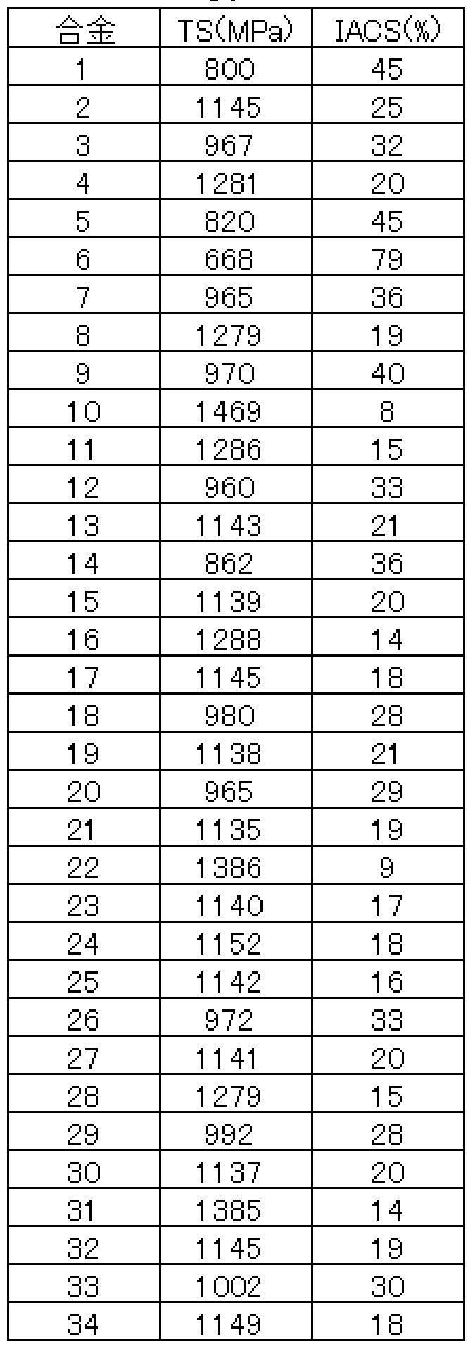
- Example A In exactly the same way as in Example A, a Cu alloy (34 types) having the composition shown in Table 3 was melted and subjected to continuous production tests under different manufacturing conditions, and evaluated in exactly the same manner as in Example A. did. Tables 4 and 5 show the results. In the method of the present invention, good results were obtained for any type, any manufacturing condition, and any chemical composition. On the other hand, in the comparative example in which the type ⁇ was changed, the quality was satisfactory and the result was not obtained.
- the cooled pieces are cold rolled to 3 mm, then aged at 400 ° C for 2 hours in an inert gas atmosphere, cold rolled to 0.5 mm again, and finally aged at 350 ° C for 6 hours Processed.
- the conductivity of the obtained test material and the tensile strength by a tensile test were evaluated by the following methods.
- a test piece having a width of 10 mm and a length of 60 mm was sampled from the above test material, and a current was passed in the longitudinal direction of the test piece to measure a potential difference between both ends of the test piece, and an electric resistance was obtained by a four-terminal method. Subsequently, the electrical resistance (resistivity) per unit volume was calculated from the volume of the test piece measured with a micrometer, and the specific force with the resistivity of the standard sample annealed with polycrystalline pure copper, 1.72 ⁇ cm, was also determined by the conductivity [IACS ( %;)].
- the cooling rate is lower than 0.5 ° C / s, which is the comparative method, cracks occur during cold rolling, and even if cold rolling is performed, the balance between strength and conductivity is poor.
- the method of the present invention has a good balance between the two, and has a high tensile strength in relation to the electrical conductivity.
- IACS means the percentage with respect to the electrical conductivity of the pure copper polycrystalline material.
- Table 7 shows the results of the same evaluation of the properties of the alloys shown in Table 3 under the above manufacturing conditions, with the cooling rate from the start of solidification to 600 ° C being 5 ° C / s. As a result, all the alloys had a balance between strength and electrical conductivity satisfying the above equation (1), and good results were obtained by the present invention.
- the present invention relates to a continuous structure used mainly for a direct connection type continuous structure in which a holding furnace is directly connected to a mold, and a method for continuously manufacturing a Cu alloy using the continuous structure. That is, the present invention provides a mold capable of continuously and efficiently producing a healthy piece, and furthermore, has properties, such as strength and conductivity, or impact resistance, of a final product after processing and heat treatment. It provides a continuous production method for Cu alloys with excellent fatigue strength, and is particularly susceptible to carbide formation./ For the production of Cu alloys containing the elements Zr, Ti, Cr, Ta, V, etc. Big effect when applied can get.
- FIG. 1 is an example of a continuous fabrication type according to the present invention.
- FIG. 2 is an example of a continuous molding type according to the present invention, in which a coating 8 of a self-lubricating material or a metal-based self-lubricating composite material is applied to an inner wall of the type III, which is opposed to a solidification start position of a molten Cu alloy. ing.
- FIG. 3 is an example of a continuous forming machine for Cu alloy according to the present invention, which uses a die formed of a plurality of member members.
- FIG. 4 is an example of a continuous molding die according to the present invention, which is constituted by a plurality of die members and has a self-lubricating material or metal on an inner wall of the die which is opposed to a solidification start position of a molten Cu alloy.
- FIG. 1 is a schematic view of a continuous production mold for a Cu alloy provided with a coating 8 of a self-lubricating composite material.
- FIG. 5 shows another example of the continuous fabrication type according to the present invention.
- a coating 9 made of a ceramic material is applied to the inner wall of the rectangular shape opposite to the molten Cu alloy for the purpose of suppressing the reaction with the molten metal.
- FIG. 6 shows another example of the continuous structure type according to the present invention.
- a metal-based self-lubricating composite material coating 8 is applied to the inner wall of the ⁇ type opposite to the solidification start position of the molten Cu alloy, and the purpose is to suppress the reaction with the molten metal on the inner wall of the ⁇ ⁇ type facing the molten Cu alloy.
- a coating 9 of a ceramic material is applied.
- FIG. 7 shows another example of the continuous fabrication type according to the present invention.
- the metal material member constitutes the upstream part of the mold, and the graphite material member constitutes the downstream part of the mold.
- the metal-based self-lubrication is applied to the inner wall of the mold, which is opposite to the solidification start position of the molten Cu alloy.
- a coating 8 of a conductive composite material is applied, and a coating 9 made of a ceramic material is applied to the inner wall of the ⁇ shape facing the molten Cu alloy for the purpose of suppressing the reaction with the molten metal.
- FIG. 8 is a state diagram of a Ti—Cr alloy.
- FIG. 9 is a state diagram of a Zr—Cr alloy.
- FIG. 10 is a state diagram of a TVZr alloy.
Abstract
Description


Claims
Priority Applications (2)
| Application Number | Priority Date | Filing Date | Title |
|---|---|---|---|
| EP04787939A EP1688198A4 (en) | 2003-09-24 | 2004-09-21 | Continuous casting mold and method of continuous casting for copper alloy |
| JP2005514086A JP4333881B2 (en) | 2003-09-24 | 2004-09-21 | Continuous casting mold and copper alloy continuous casting method |
Applications Claiming Priority (6)
| Application Number | Priority Date | Filing Date | Title |
|---|---|---|---|
| JP2003331909 | 2003-09-24 | ||
| JP2003-331909 | 2003-09-24 | ||
| JP2004097223 | 2004-03-29 | ||
| JP2004-097223 | 2004-03-29 | ||
| JP2004234641 | 2004-08-11 | ||
| JP2004-234641 | 2004-08-11 |
Publications (1)
| Publication Number | Publication Date |
|---|---|
| WO2005028143A1 true WO2005028143A1 (en) | 2005-03-31 |
Family
ID=34381782
Family Applications (1)
| Application Number | Title | Priority Date | Filing Date |
|---|---|---|---|
| PCT/JP2004/013756 WO2005028143A1 (en) | 2003-09-24 | 2004-09-21 | Continuous casting mold and method of continuous casting for copper alloy |
Country Status (5)
| Country | Link |
|---|---|
| US (1) | US20060180293A1 (en) |
| EP (1) | EP1688198A4 (en) |
| JP (1) | JP4333881B2 (en) |
| TW (1) | TWI272145B (en) |
| WO (1) | WO2005028143A1 (en) |
Cited By (16)
| Publication number | Priority date | Publication date | Assignee | Title |
|---|---|---|---|---|
| DE102006015282A1 (en) * | 2006-04-01 | 2007-10-04 | Honeywell Technologies Sarl Ecc | Bronze casting mold with thermal insulation lining and casting process for manufacture of drinking water valve housing and fittings |
| JP2009242882A (en) * | 2008-03-31 | 2009-10-22 | Nippon Mining & Metals Co Ltd | Titanium copper suitable for precise press working |
| JP2011036903A (en) * | 2009-08-18 | 2011-02-24 | Materials Solution Inc | Method for manufacturing copper alloy |
| CN102476177A (en) * | 2010-11-29 | 2012-05-30 | 株洲南方有色焊材有限公司 | Upward drawing method for copper alloy wire blank |
| CN103695697A (en) * | 2013-12-03 | 2014-04-02 | 江苏帕齐尼铜业有限公司 | Copper-chromium alloy and preparation method thereof |
| JP2014095107A (en) * | 2012-11-07 | 2014-05-22 | Fujikura Ltd | Cu-Mg ALLOY BODY, MANUFACTURING METHOD OF Cu-Mg ALLOY BODY AND DRAWN WIRE MATERIAL |
| CN104051076A (en) * | 2014-06-05 | 2014-09-17 | 锐展(铜陵)科技有限公司 | Method for preparing low-expansion copper alloy wire used for automotive cables and cords |
| CN104046842A (en) * | 2014-06-05 | 2014-09-17 | 锐展(铜陵)科技有限公司 | Preparation method of high-content nickel-copper alloy wire for electronic instrument of automobile |
| CN104046838A (en) * | 2014-06-05 | 2014-09-17 | 锐展(铜陵)科技有限公司 | Preparation method of high-strength high-toughness copper alloy wire for automatic cables |
| CN104046837A (en) * | 2014-06-05 | 2014-09-17 | 锐展(铜陵)科技有限公司 | Making method of leadless copper alloy wire for automobile industry |
| CN104152728A (en) * | 2014-06-05 | 2014-11-19 | 锐展(铜陵)科技有限公司 | Preparation method of high heat-conducting copper alloy wire for automobile wire harness |
| KR20180125449A (en) * | 2016-03-30 | 2018-11-23 | 미쓰비시 마테리알 가부시키가이샤 | Copper alloy for electronic and electric equipment, Copper alloy plate for electronic and electric equipment, Parts for electronic and electric equipment, Terminal, bus bar, and movable part for relay |
| US11104977B2 (en) | 2018-03-30 | 2021-08-31 | Mitsubishi Materials Corporation | Copper alloy for electronic/electric device, copper alloy sheet/strip material for electronic/electric device, component for electronic/electric device, terminal, and busbar |
| US11203806B2 (en) | 2016-03-30 | 2021-12-21 | Mitsubishi Materials Corporation | Copper alloy for electronic and electrical equipment, copper alloy plate strip for electronic and electrical equipment, component for electronic and electrical equipment, terminal, busbar, and movable piece for relay |
| US11319615B2 (en) | 2016-03-30 | 2022-05-03 | Mitsubishi Materials Corporation | Copper alloy for electronic and electrical equipment, copper alloy plate strip for electronic and electrical equipment, component for electronic and electrical equipment, terminal, busbar, and movable piece for relay |
| US11655523B2 (en) | 2018-03-30 | 2023-05-23 | Mitsubishi Materials Corporation | Copper alloy for electronic/electric device, copper alloy sheet/strip material for electronic/electric device, component for electronic/electric device, terminal, and busbar |
Families Citing this family (36)
| Publication number | Priority date | Publication date | Assignee | Title |
|---|---|---|---|---|
| CN103056318B (en) * | 2008-03-05 | 2017-06-09 | 南线有限责任公司 | As the niobium of the protective wall in motlten metal |
| WO2011027858A1 (en) * | 2009-09-07 | 2011-03-10 | 株式会社 白金 | Copper alloy and method for producing same |
| US8652397B2 (en) | 2010-04-09 | 2014-02-18 | Southwire Company | Ultrasonic device with integrated gas delivery system |
| DK2556176T3 (en) | 2010-04-09 | 2020-05-04 | Southwire Co Llc | Ultrasonic degassing of molten metals |
| CN102634688B (en) * | 2011-02-10 | 2014-05-07 | 湖南特力新材料有限公司 | Leadless free-cutting copper alloy and preparation method |
| JP5802150B2 (en) * | 2012-02-24 | 2015-10-28 | 株式会社神戸製鋼所 | Copper alloy |
| CN103114218B (en) * | 2013-03-11 | 2014-07-16 | 武汉大学 | Preparation method of copper-chrome alloy |
| CN103114222B (en) * | 2013-03-14 | 2014-10-22 | 上海天申铜业集团有限公司 | Casting method of lead-free water meter case |
| BR112016011262B1 (en) | 2013-11-18 | 2021-05-18 | Southwire Company, Llc | ultrasonic device and method for reducing an amount of a dissolved gas and/or an impurity in a molten metal bath |
| CN104046831A (en) * | 2014-06-05 | 2014-09-17 | 锐展(铜陵)科技有限公司 | Making method of copper alloy wire for automobiles |
| CN104046832A (en) * | 2014-06-05 | 2014-09-17 | 锐展(铜陵)科技有限公司 | Making method of highly conductive copper alloy wire or automobile generator |
| JP6488951B2 (en) * | 2014-09-25 | 2019-03-27 | 三菱マテリアル株式会社 | Mold material for casting and Cu-Cr-Zr alloy material |
| CN104588618B (en) * | 2014-11-28 | 2017-01-18 | 太原科技大学 | Continuous casting device of magnesium alloy composite board |
| CN104475468B (en) * | 2014-12-09 | 2016-08-24 | 中色(天津)特种材料有限公司 | N6 nickel alloy wire continuous casting even pulls out processing technique |
| JP6228941B2 (en) * | 2015-01-09 | 2017-11-08 | Jx金属株式会社 | Titanium copper with plating layer |
| CN104630546A (en) * | 2015-03-05 | 2015-05-20 | 苏州市凯业金属制品有限公司 | High-strength heat-resistant copper alloy metal tube |
| CN104928528A (en) * | 2015-07-06 | 2015-09-23 | 苏州科茂电子材料科技有限公司 | Conductive copper alloy material and preparing method thereof |
| CN104928523A (en) * | 2015-07-10 | 2015-09-23 | 苏州科茂电子材料科技有限公司 | Copper alloy lead material for communication cable and preparing method thereof |
| US10233515B1 (en) | 2015-08-14 | 2019-03-19 | Southwire Company, Llc | Metal treatment station for use with ultrasonic degassing system |
| CN105108079A (en) * | 2015-09-24 | 2015-12-02 | 云南新铜人实业有限公司 | Horizontal continuous casting copper belt production process |
| CN106111931B (en) * | 2016-06-28 | 2018-06-05 | 北京科技大学 | A kind of metal clad material solid-liquid continuous casting composite forming apparatus and process |
| CN106424613A (en) * | 2016-11-29 | 2017-02-22 | 郑州中拓知识产权代理有限公司 | Copper rod continuous casting machine |
| KR101830841B1 (en) | 2016-11-29 | 2018-02-22 | 한국생산기술연구원 | Copper alloys having high wear resistant for synchronizer ring and manufacturing method thereof |
| CN106735003B (en) * | 2016-12-08 | 2018-09-28 | 北京科技大学 | A kind of non-vacuum melting horizontal casting production technology of high-strength highly-conductive Cu-Cr-Zr alloy bar materials |
| CN106583672B (en) * | 2016-12-09 | 2018-09-25 | 北京科技大学 | A kind of copper chromium alloy horizontal continuous casting process |
| CN107511469A (en) * | 2017-10-13 | 2017-12-26 | 安阳恒安电机有限公司 | A kind of squirrel cage motor rotor low pressure cast copper equipment, cast copper and its cast copper method |
| CN110396621B (en) * | 2019-08-27 | 2020-12-08 | 天长市华海电子科技有限公司 | Intergranular corrosion resistant forging piece and preparation method thereof |
| CN113458352B (en) | 2020-03-30 | 2023-11-24 | 日本碍子株式会社 | Method for producing Cu-Ni-Sn alloy and cooler for use in same |
| CN111850345B (en) * | 2020-07-23 | 2021-06-18 | 唐山中科量子激光科技有限公司 | Wear-resistant high-temperature-erosion-resistant alloy material, crystallizer copper plate surface treatment method and crystallizer copper plate |
| CN112355263A (en) * | 2020-10-14 | 2021-02-12 | 刘珍 | Semi-solid forming device for aluminum alloy processing |
| JP7433263B2 (en) * | 2021-03-03 | 2024-02-19 | 日本碍子株式会社 | Manufacturing method of Cu-Ni-Sn alloy |
| JP2023012240A (en) * | 2021-07-13 | 2023-01-25 | 昭和電工株式会社 | Horizontal continuous casting apparatus, aluminum alloy cast rod manufacturing method |
| CN113680980B (en) * | 2021-09-06 | 2022-12-09 | 西安斯瑞先进铜合金科技有限公司 | Production process for horizontally continuously casting copper-manganese alloy |
| CN114012052B (en) * | 2021-12-30 | 2022-05-03 | 东北大学 | Horizontal continuous casting equipment for aluminum alloy cast ingot |
| CN115786752A (en) * | 2022-11-24 | 2023-03-14 | 有研工程技术研究院有限公司 | Method for improving corrosion resistance of cupronickel alloy pipe |
| CN115852201A (en) * | 2022-12-28 | 2023-03-28 | 北冶功能材料(江苏)有限公司 | Production method of copper-nickel-tin alloy ingot |
Citations (9)
| Publication number | Priority date | Publication date | Assignee | Title |
|---|---|---|---|---|
| JPS58123862A (en) * | 1982-01-20 | 1983-07-23 | Nippon Mining Co Ltd | Manufacture of copper alloy for lead material for semiconductor apparatus |
| JPS61169149A (en) * | 1985-01-22 | 1986-07-30 | Nippon Mining Co Ltd | Continuous casting method |
| JPH03155436A (en) * | 1989-11-10 | 1991-07-03 | Sumitomo Light Metal Ind Ltd | Horizontal continuous casting method |
| JPH03210942A (en) * | 1990-01-11 | 1991-09-13 | Sumitomo Metal Ind Ltd | Method for continuously casting steel |
| JPH04266457A (en) * | 1991-02-22 | 1992-09-22 | Hitachi Cable Ltd | Casting mold for continuous casting |
| JPH05318034A (en) * | 1992-05-22 | 1993-12-03 | Furukawa Electric Co Ltd:The | Complex graphite mold for continuous casting |
| JPH06179930A (en) * | 1992-08-25 | 1994-06-28 | Tatsuta Electric Wire & Cable Co Ltd | Graphite-made crucible or mold |
| JPH09141394A (en) * | 1995-11-17 | 1997-06-03 | Sumitomo Metal Ind Ltd | Mold for continuous casting, its manufacture and using method thereof |
| JPH11147162A (en) * | 1997-11-13 | 1999-06-02 | Tokai Carbon Co Ltd | Graphite mold for continuous casting |
Family Cites Families (9)
| Publication number | Priority date | Publication date | Assignee | Title |
|---|---|---|---|---|
| US3424228A (en) * | 1966-04-08 | 1969-01-28 | Ducommun Inc | Anisotropic mold liner for continuous casting of metals |
| US3435881A (en) * | 1967-01-03 | 1969-04-01 | Carbone Corp | Anisotropic continuous casting mold |
| DE2634633C2 (en) * | 1976-07-31 | 1984-07-05 | Kabel- und Metallwerke Gutehoffnungshütte AG, 3000 Hannover | Continuous casting mold made of a copper material, especially for continuous casting of steel |
| DE2657207C2 (en) * | 1976-12-17 | 1978-10-05 | Kreidler Werke Gmbh, 7000 Stuttgart | Process for the continuous casting of metal alloys, in particular brass alloys and continuous casting mold for carrying out the process |
| JPS5785652A (en) * | 1980-11-19 | 1982-05-28 | Kawasaki Steel Corp | Continuous casting method for hollow blank material for pipe making |
| JPS59133942A (en) * | 1983-01-21 | 1984-08-01 | Kobe Steel Ltd | Inside surface treatment of mold for horizontal continuous casting |
| US5171491A (en) * | 1986-02-04 | 1992-12-15 | The Carborundum Company | Method of producing near net shape fused cast refractories |
| JPH026037A (en) * | 1988-06-27 | 1990-01-10 | Nkk Corp | Method for continuously casting steel |
| CH695210A5 (en) * | 2000-12-11 | 2006-01-31 | Concast Ag | Mold for the continuous casting of molten steel. |
-
2004
- 2004-09-21 EP EP04787939A patent/EP1688198A4/en not_active Withdrawn
- 2004-09-21 WO PCT/JP2004/013756 patent/WO2005028143A1/en not_active Application Discontinuation
- 2004-09-21 JP JP2005514086A patent/JP4333881B2/en not_active Expired - Fee Related
- 2004-09-23 TW TW093128891A patent/TWI272145B/en not_active IP Right Cessation
-
2006
- 2006-03-23 US US11/386,924 patent/US20060180293A1/en not_active Abandoned
Patent Citations (9)
| Publication number | Priority date | Publication date | Assignee | Title |
|---|---|---|---|---|
| JPS58123862A (en) * | 1982-01-20 | 1983-07-23 | Nippon Mining Co Ltd | Manufacture of copper alloy for lead material for semiconductor apparatus |
| JPS61169149A (en) * | 1985-01-22 | 1986-07-30 | Nippon Mining Co Ltd | Continuous casting method |
| JPH03155436A (en) * | 1989-11-10 | 1991-07-03 | Sumitomo Light Metal Ind Ltd | Horizontal continuous casting method |
| JPH03210942A (en) * | 1990-01-11 | 1991-09-13 | Sumitomo Metal Ind Ltd | Method for continuously casting steel |
| JPH04266457A (en) * | 1991-02-22 | 1992-09-22 | Hitachi Cable Ltd | Casting mold for continuous casting |
| JPH05318034A (en) * | 1992-05-22 | 1993-12-03 | Furukawa Electric Co Ltd:The | Complex graphite mold for continuous casting |
| JPH06179930A (en) * | 1992-08-25 | 1994-06-28 | Tatsuta Electric Wire & Cable Co Ltd | Graphite-made crucible or mold |
| JPH09141394A (en) * | 1995-11-17 | 1997-06-03 | Sumitomo Metal Ind Ltd | Mold for continuous casting, its manufacture and using method thereof |
| JPH11147162A (en) * | 1997-11-13 | 1999-06-02 | Tokai Carbon Co Ltd | Graphite mold for continuous casting |
Non-Patent Citations (1)
| Title |
|---|
| See also references of EP1688198A4 * |
Cited By (19)
| Publication number | Priority date | Publication date | Assignee | Title |
|---|---|---|---|---|
| DE102006015282A1 (en) * | 2006-04-01 | 2007-10-04 | Honeywell Technologies Sarl Ecc | Bronze casting mold with thermal insulation lining and casting process for manufacture of drinking water valve housing and fittings |
| JP2009242882A (en) * | 2008-03-31 | 2009-10-22 | Nippon Mining & Metals Co Ltd | Titanium copper suitable for precise press working |
| JP2011036903A (en) * | 2009-08-18 | 2011-02-24 | Materials Solution Inc | Method for manufacturing copper alloy |
| CN102476177A (en) * | 2010-11-29 | 2012-05-30 | 株洲南方有色焊材有限公司 | Upward drawing method for copper alloy wire blank |
| CN102476177B (en) * | 2010-11-29 | 2013-05-29 | 株洲南方有色焊材有限公司 | Upward drawing method for copper alloy wire blank |
| JP2014095107A (en) * | 2012-11-07 | 2014-05-22 | Fujikura Ltd | Cu-Mg ALLOY BODY, MANUFACTURING METHOD OF Cu-Mg ALLOY BODY AND DRAWN WIRE MATERIAL |
| CN103695697B (en) * | 2013-12-03 | 2016-04-20 | 江苏帕齐尼铜业有限公司 | A kind of chromiumcopper and preparation method thereof |
| CN103695697A (en) * | 2013-12-03 | 2014-04-02 | 江苏帕齐尼铜业有限公司 | Copper-chromium alloy and preparation method thereof |
| CN104051076A (en) * | 2014-06-05 | 2014-09-17 | 锐展(铜陵)科技有限公司 | Method for preparing low-expansion copper alloy wire used for automotive cables and cords |
| CN104046842A (en) * | 2014-06-05 | 2014-09-17 | 锐展(铜陵)科技有限公司 | Preparation method of high-content nickel-copper alloy wire for electronic instrument of automobile |
| CN104046838A (en) * | 2014-06-05 | 2014-09-17 | 锐展(铜陵)科技有限公司 | Preparation method of high-strength high-toughness copper alloy wire for automatic cables |
| CN104046837A (en) * | 2014-06-05 | 2014-09-17 | 锐展(铜陵)科技有限公司 | Making method of leadless copper alloy wire for automobile industry |
| CN104152728A (en) * | 2014-06-05 | 2014-11-19 | 锐展(铜陵)科技有限公司 | Preparation method of high heat-conducting copper alloy wire for automobile wire harness |
| KR20180125449A (en) * | 2016-03-30 | 2018-11-23 | 미쓰비시 마테리알 가부시키가이샤 | Copper alloy for electronic and electric equipment, Copper alloy plate for electronic and electric equipment, Parts for electronic and electric equipment, Terminal, bus bar, and movable part for relay |
| KR102296652B1 (en) | 2016-03-30 | 2021-08-31 | 미쓰비시 마테리알 가부시키가이샤 | Copper alloy for electronic and electric equipment, copper alloy plate for electronic and electric equipment, electronic and electric equipment parts, terminal, bus bar, and movable piece for relay |
| US11203806B2 (en) | 2016-03-30 | 2021-12-21 | Mitsubishi Materials Corporation | Copper alloy for electronic and electrical equipment, copper alloy plate strip for electronic and electrical equipment, component for electronic and electrical equipment, terminal, busbar, and movable piece for relay |
| US11319615B2 (en) | 2016-03-30 | 2022-05-03 | Mitsubishi Materials Corporation | Copper alloy for electronic and electrical equipment, copper alloy plate strip for electronic and electrical equipment, component for electronic and electrical equipment, terminal, busbar, and movable piece for relay |
| US11104977B2 (en) | 2018-03-30 | 2021-08-31 | Mitsubishi Materials Corporation | Copper alloy for electronic/electric device, copper alloy sheet/strip material for electronic/electric device, component for electronic/electric device, terminal, and busbar |
| US11655523B2 (en) | 2018-03-30 | 2023-05-23 | Mitsubishi Materials Corporation | Copper alloy for electronic/electric device, copper alloy sheet/strip material for electronic/electric device, component for electronic/electric device, terminal, and busbar |
Also Published As
| Publication number | Publication date |
|---|---|
| JPWO2005028143A1 (en) | 2007-11-15 |
| TW200528213A (en) | 2005-09-01 |
| EP1688198A4 (en) | 2007-03-21 |
| TWI272145B (en) | 2007-02-01 |
| JP4333881B2 (en) | 2009-09-16 |
| EP1688198A1 (en) | 2006-08-09 |
| US20060180293A1 (en) | 2006-08-17 |
Similar Documents
| Publication | Publication Date | Title |
|---|---|---|
| WO2005028143A1 (en) | Continuous casting mold and method of continuous casting for copper alloy | |
| JPWO2005072891A1 (en) | Copper alloy continuous casting method | |
| Rajabi et al. | Chemical composition, microstructure and sintering temperature modifications on mechanical properties of TiC-based cermet–A review | |
| TW457154B (en) | Electrode for surface treatment by electric discharge, process for making the same, method and apparatus for surface treatment by electric discharge | |
| JP2002503764A (en) | Aluminide sheet manufacturing method by thermomechanical processing of aluminide powder | |
| WO2006104152A1 (en) | Copper alloy and process for producing the same | |
| WO2004070070A1 (en) | Cu ALLOY AND METHOD FOR PRODUCTION THEREOF | |
| Li et al. | Microstructure and mechanical properties of the Ni-B-Ti composite coating on TA2 prepared by pre-plating and laser remelting | |
| WO2014008011A1 (en) | Consumer electronics machined housing using coating that exhibit metamorphic transformation | |
| JP2001271129A (en) | Sintering material and composite sintered sliding part | |
| CN109913719B (en) | Magnesium alloy, method for producing same, and electronic device | |
| EP1594644B1 (en) | Formation of metallic thermal barrier alloys | |
| JP2007016288A (en) | Method for manufacturing sliding member coated with bearing material and sliding member coated with bearing material | |
| Aramian et al. | A review on the microstructure and properties of TiC and Ti (C, N) based cermets | |
| CN102686337B (en) | Process for producing copper alloy wire containing active element | |
| Kumar et al. | Coatings on reinforcements in aluminum metal matrix composites | |
| CN101574761B (en) | Powder-cored welding wire used for surface cladding of high-temperature thermocouple protection tube and preparation method thereof | |
| TW576767B (en) | Ingot-mold wall, especially a broad side wall of a continuous casting mold for steel | |
| KR100292119B1 (en) | Electrode material, method for manufacturing electrode material, and method for manufacturing electrode | |
| KR100740899B1 (en) | Mold wall, especially a broadside wall of a continuous casting mold for steel | |
| WO2012164581A2 (en) | A process for producing reinforced aluminum-metal matrix composites | |
| JPS616242A (en) | Fiber reinforced metallic composite material | |
| US3764308A (en) | Multi phase strip from particle and powder mixture | |
| Cao et al. | Mechanical properties of iron matrix composites reinforced by copper-coated hybrid ceramic particles | |
| US3819311A (en) | Apparatus for forming multi-phase strip from particle and powder mixture |
Legal Events
| Date | Code | Title | Description |
|---|---|---|---|
| AK | Designated states |
Kind code of ref document: A1 Designated state(s): AE AG AL AM AT AU AZ BA BB BG BW BY BZ CA CH CN CO CR CU CZ DK DM DZ EC EE EG ES FI GB GD GE GM HR HU ID IL IN IS JP KE KG KP KZ LC LK LR LS LT LU LV MA MD MK MN MW MX MZ NA NI NO NZ PG PH PL PT RO RU SC SD SE SG SK SY TJ TM TN TR TT TZ UA UG US UZ VN YU ZA ZM |
|
| AL | Designated countries for regional patents |
Kind code of ref document: A1 Designated state(s): BW GH GM KE LS MW MZ NA SD SZ TZ UG ZM ZW AM AZ BY KG MD RU TJ TM AT BE BG CH CY DE DK EE ES FI FR GB GR HU IE IT MC NL PL PT RO SE SI SK TR BF CF CG CI CM GA GN GQ GW ML MR SN TD TG |
|
| 121 | Ep: the epo has been informed by wipo that ep was designated in this application | ||
| WWE | Wipo information: entry into national phase |
Ref document number: 2006103368 Country of ref document: RU |
|
| WWE | Wipo information: entry into national phase |
Ref document number: 2005514086 Country of ref document: JP |
|
| WWE | Wipo information: entry into national phase |
Ref document number: 2004787939 Country of ref document: EP |
|
| WWE | Wipo information: entry into national phase |
Ref document number: 11386924 Country of ref document: US |
|
| DPEN | Request for preliminary examination filed prior to expiration of 19th month from priority date (pct application filed from 20040101) | ||
| WWP | Wipo information: published in national office |
Ref document number: 2004787939 Country of ref document: EP |
|
| WWW | Wipo information: withdrawn in national office |
Ref document number: 2004787939 Country of ref document: EP |