EP1687871B1 - Elektrischer Verbinder mit einer Klammer zum Ergreifen von hervortretenden Kabeln - Google Patents
Elektrischer Verbinder mit einer Klammer zum Ergreifen von hervortretenden Kabeln Download PDFInfo
- Publication number
- EP1687871B1 EP1687871B1 EP04817393A EP04817393A EP1687871B1 EP 1687871 B1 EP1687871 B1 EP 1687871B1 EP 04817393 A EP04817393 A EP 04817393A EP 04817393 A EP04817393 A EP 04817393A EP 1687871 B1 EP1687871 B1 EP 1687871B1
- Authority
- EP
- European Patent Office
- Prior art keywords
- jaws
- electric connector
- clamp
- hinge
- cables
- Prior art date
- Legal status (The legal status is an assumption and is not a legal conclusion. Google has not performed a legal analysis and makes no representation as to the accuracy of the status listed.)
- Expired - Lifetime
Links
Images

Classifications
-
- H—ELECTRICITY
- H01—ELECTRIC ELEMENTS
- H01R—ELECTRICALLY-CONDUCTIVE CONNECTIONS; STRUCTURAL ASSOCIATIONS OF A PLURALITY OF MUTUALLY-INSULATED ELECTRICAL CONNECTING ELEMENTS; COUPLING DEVICES; CURRENT COLLECTORS
- H01R13/00—Details of coupling devices of the kinds covered by groups H01R12/70 or H01R24/00 - H01R33/00
- H01R13/58—Means for relieving strain on wire connection, e.g. cord grip, for avoiding loosening of connections between wires and terminals within a coupling device terminating a cable
- H01R13/5804—Means for relieving strain on wire connection, e.g. cord grip, for avoiding loosening of connections between wires and terminals within a coupling device terminating a cable comprising a separate cable clamping part
- H01R13/5812—Means for relieving strain on wire connection, e.g. cord grip, for avoiding loosening of connections between wires and terminals within a coupling device terminating a cable comprising a separate cable clamping part the cable clamping being achieved by mounting the separate part on the housing of the coupling device
Definitions
- the present invention relates to a clamp for gripping cables issuing from an electric connector, particularly of the type used in automotive applications.
- each connector normally comprises an insulating casing, which defines a number of cavities having axes parallel to the coupling direction of the connector to the complementary connector, and housing, in use, respective electric terminals connected electrically to the terminals of the complementary connector.
- the terminals are retained inside the respective cavities by elastic retaining lances, and are connected to respective electric cables issuing from the insulating casing through an end wall.
- a portion of the cables outside the insulating casing is gripped between two jaws to hold the cables in place and prevent in-service vibration, any inaccuracy or excessive pull during assembly, and/or excessive pull on the cables after assembly, from impairing electric contact of the terminals and, therefore, signal transmission and/or power supply of the vehicle.
- a slide body is provided, which slides over and forces the jaws onto the cables, e.g. by means of a cam or ramp coupling.
- fitters when assembling the connector and electric system to the vehicle, are not always able to determine proper fit of the slide body, or correct grip of the cables by the jaws, on account of the jaws and the cable portions to be gripped being concealed by the slide body.
- DE-A-3108744 discloses a clamp according the preamble of claim 1.
- US-A-5961351 discloses a Universal Serial B-Plug connector consisting of a dielectric casing defining a front recess for receiving a mating receptacle connector, four rear trenches defined by a horizontal partition and a vertical partition mutually perpendicular to each other and four mounting channels connecting the trenches with the recess, respectively.
- Four contact pieces each have a contact extending into the recess, a mounting section forcedly fitted into the one of the mounting channels, and a terminal portion snugly fitted into one of the trenches.
- a rear shield frame portion has a base plate abuting a rear end of the dielectric casing and two wings clipping a cable connected with the connector.
- a front shield frame portion has locking hooks at a rear end thereof which are securely fixed to mounting slots of the base plate, whereby the front shield frame portion cooperates with the rear shield frame portion to electromagnetically shield the dielectric housing.
- an electric connector according to claim 1.
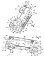
- Number 1 in the accompanying drawings indicates a clamp for gripping cables 2 issuing from an electric connector 3 (shown partly).
- connector 3 comprises an insulating casing 4 defining a front cavity 5 engaged, in use, by a complementary connector (not shown), and a number of parallel, side by side channels 6 (only one shown), which communicate with cavity 5, have respective axes A parallel to a longitudinal coupling direction of connector 3 to the complementary connector, and come out through respective openings 7 formed in a rear portion 8 of casing 4.
- Channels 6 house respective known male electric terminals 9 connected in fixed positions to casing 4, in known manner not described in detail, and each of which comprises a blade-type end contact portion 10 projecting inside cavity 5, and a connecting portion 11 for connection to a respective electric cable 2.
- Cables 2 extend from portion 8, in a direction parallel to respective terminals 9, through openings 7, and comprise respective portions 13 outside casing 4 and which are gripped by clamp 1.
- portion 8 comprises two parallel lateral faces 14 (only one shown), from each of which project integrally a pair of appendixes 15, 16, and a cylindrical pin 17 interposed between appendixes 15, 16 along a plane P ( Figures 5 and 6 ) containing axes A of channels 6 and openings 7.
- the two pins 17 are coaxial along an axis lying in plane P; appendixes 15 are located on the end edge of portion 8, are symmetrical in shape with respect to plane P, and define respective V-shaped seats 19 facing pins 17; and appendixes 16 define respective concave surfaces 20 facing and coaxial with pins 17.
- pins 17 define a hinge, about which clamp 1 is mounted to rotate. More specifically, clamp 1 is formed in one piece, preferably from plastic material, and comprises two jaws 21, 22 joined by a virtual hinge 23, which is defined by two arc-shaped portions 24 spaced apart and coaxial with each other along an axis C parallel to the axis of pins 17.
- Portions 24 are housed between pins 17 and surfaces 20, define respective substantially circular seats 26 engaged radially loosely by pins 17, have ends 27 defining respective intermediate openings 28 between jaws 21, 22, and are deformable elastically to enable jaws 21, 22 to rotate, with respect to each other and about axis C, between a parted open position ( Figure 6 ), and a closed position ( Figure 7 ) gripping portions 13 of cables 2.
- Clamp 1 also comprises an elastic parting device 30, which is interposed between jaws 21, 22, is spaced apart from hinge 23 in a direction perpendicular to axis C, and exerts elastic thrust on jaws 21, 22 to push the jaws into the open position.
- Device 30 comprises two elastically deformable portions 31, which are aligned and spaced apart in a direction parallel to axis C, are integral with portions 24, and extend from ends 27 and face openings 28 to define, together with portions 24, two elastically deformable rings 33 shaped symmetrically with respect to a mid-plane of clamp 1 containing axis C.
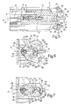
- Portions 31 are ogival in shape, and comprise respective pairs of arc-shaped, outwardly-convex branches or blades 34 joined at respective tips 35, which face away from hinge 23 and at least partly engage seats 19 to keep clamp 1 in an angularly fixed reference position in which jaws 21, 22 are positioned symmetrically with respect to plane P.
- jaws 21, 22 are U-shaped, and each comprise two lateral arms 37, 38 integral with rings 33.
- the arms of each jaw 21, 22 project from ends 27, are parallel to each other, and have respective backs 39, which are at least partly knurled or ribbed for easy manual pressure by fitters.
- Jaws 21, 22 also comprise respective intermediate portions 40, 41, which extend between the ends of arms 37, 38 in a direction parallel to axis C, i.e. in a direction perpendicular to cables 2, and have respective facing surfaces 42, 43 for gripping portions 13.
- Surface 42 has a triangular-section tooth 44 parallel to axis C
- surface 43 has two teeth 45 parallel to axis C and defining, in between, a recess 46 complementary to tooth 44 and engaged by tooth 44 when jaws 21, 22 are in the closed position.
- Teeth 44, 45 have a number of grooves 47 perpendicular to axis C, and which provide for positioning and retaining cables 2 in a direction parallel to axis C.
- a conveniently click-on retaining device 49 is provided to keep jaws 21, 22 in the closed position, and comprises two hooks 50, which are integral with jaw 21, define extensions of arms 37 at opposite ends of portion 40, face tips 35, and are defined by respective convex surfaces 51 facing arms 38, and by respective flat retaining surfaces 52 facing and substantially parallel to arms 37.
- Device 49 also comprises two seats 55, which are formed in jaw 22, at opposite ends of portion 41, are complementary to hooks 50, and have respective flat retaining surfaces 56 which rest on respective surfaces 52 in the closed position.
- Surface 56 of each seat 55 is defined by a tooth 58, which engages the gap 59 between relative surface 52 and relative arm 37 in the closed position ( Figure 7 ), and has a curved, convex surface 60 which slides against surface 51 of relative hook 50 when closing jaws 21, 22.
- rings 33 are parted slightly along axis C, making use of the flexibility of the material from which clamp 1 is made; clamp 1 is fitted longitudinally onto portion 8; seats 26 are positioned along pins 17; and arms 37, 38 are released to insert portions 24 between pins 17 and surfaces 20, and to insert tips 35 inside seats 19.
- jaws 21, 22 are brought together, by pressing manually on backs 39 in opposition to the elastic parting force of rings 33, to slide surfaces 60 along surfaces 51 and click hooks 50 inside seats 55, and teeth 58 inside gaps 59.
- portions 31 spring open jaws 21, 22, thus giving the fitter both a visual and tactile indication of an improper clamping condition.
- the bulk produced by clamp 1 close to portion 8 of casing 4 is relatively small, on account of device 49 being formed in one piece with jaws 21, 22, and no additional retaining body being required to keep jaws 21, 22 in the closed position.
- Cables 2 are also clamped extremely quickly, by virtue of there being no additional retaining bodies to handle, and jaws 21, 22 being clicked together by simply pressing on arms 37, 38.
- Clamp 1 is also relatively straightforward, in that hinge 23 and device 30 also provide, respectively, for fitting jaws 21, 22 to casing 4 and keeping clamp 1 in a fixed reference position with respect to casing 4.
- surfaces 42, 43 provides for firm grip and stable positioning of cables 2 once jaws 21, 22 are closed.
- one locking or retaining member may be provided, possibly located in a different position from those shown by way of example.
- a further locking or retaining device may be provided in addition to and interposed between the two end hooks 50.
- Clamp 1 may be connected to casing 4 otherwise than as shown, e.g. by means of teeth engaging respective seats in casing 4, and/or at least one of jaws 21, 22 may be formed in one piece with casing 4.
- Jaws 21, 22 may be connected to each other by other than hinge 23, but still in such a manner as to rotate or translate between the open and closed positions, and/or axis C may be parallel as opposed to crosswise to cables 2.
- device 30 may comprise elastically deformable portions differing from portions 31, and/or elastic members separate from jaws 21, 22.
Landscapes
- Details Of Connecting Devices For Male And Female Coupling (AREA)
- Clamps And Clips (AREA)
- Connections By Means Of Piercing Elements, Nuts, Or Screws (AREA)
- Coupling Device And Connection With Printed Circuit (AREA)
- Multi-Conductor Connections (AREA)
- Connector Housings Or Holding Contact Members (AREA)
- Processing Of Terminals (AREA)
Claims (18)
- Ein elektrischer Verbinder (3) umfassend:- ein isolierendes Gehäuse (4), von dem eine Anzahl von Kabeln (2) ausgegeben werden können und- ein Befestigungselement (1), das zum Einklemmen der Kabel (2) ausgebildet ist; wobei das Befestigungselement (1) zwei Backen (21, 22) umfasst, die bezüglich zueinander beweglich sind zwischen einer getrennten offenen Position und einer geschlossenen Position, die ein Einklemmen der Kabel (2) erlaubt und Befestigungsmittel (24) zum Einpassen des Befestigungselements (1) in dem isolierenden Gehäuse (4); wobei Haltemittel (49) bereitgestellt sind, um die Backen (21, 22) in der geschlossenen Position zu halten und die in einem Stück mit den Backen (21, 22) ausgebildet sind;dadurch gekennzeichnet, dass das Befestigungselement (1) aus einem Kunststoffmaterial ausgebildet ist und direkt mittels der Befestigungsmittel (24) mit dem isolierenden Gehäuse (4) verbunden ist.
- Ein elektrischer Verbinder, wie in Anspruch 1 beansprucht, dadurch gekennzeichnet, dass die Befestigungsmittel (24) und die Backen (21, 22) an gegenüberliegenden Enden des Befestigungselements (1) angeordnet sind.
- Ein elektrischer Verbinder, wie in Anspruch 1 oder 2 beansprucht, dadurch gekennzeichnet, dass das Befestigungselement (1) ein Gelenk (23) umfasst, das es den Backen (21, 22) erlaubt, zwischen der offenen Position und der geschlossenen Position um eine Gelekachse (C) zu drehen; und ein elastisches Trennmittel (30), das zwischen den Backen (21, 22) eingefügt ist, beabstandet von dem Gelenk (23) und eine elastische Kraft auf die Backen (21, 22) ausübt, um die Backen in die geöffnete Position zu drücken.
- Ein elektrischer Verbinder, wie Anspruch 3 beansprucht, dadurch gekennzeichnet, dass das Gelenk (23) elastische deformierbare Abschnitte (24) umfasst, wobei diese einen Teil der Befestigungsmittel (24) ausbilden.
- Ein elektrischer Verbinder, wie in Anspruch 3 oder 4 beansprucht, dadurch gekennzeichnet, dass die elastischen Trennmittel (30) in einem Stück mit den Backen (21, 22) ausgebildet sind.
- Ein elektrischer Verbinder, wie in Anspruch 5 beansprucht, dadurch gekennzeichnet, dass die elastischen Mittel (30) und das Gelenk (23) gemeinsam zwei elastische deformierbare Ringe (33) definieren, die co-axial zueinander sind und beabstandet entlang der Gelenkachse (C) sind; wobei die Backen (21, 22) von dem Ringen (33) hervorstehen.
- Ein elektrischer Verbinder, wie Anspruch 6 beansprucht, dadurch gekennzeichnet, dass jeder der Ringe (33) in Bezug zu einer Mittelebene des Befestigungselements (1), die die Gelenkachse (C) beinhaltet, symmetrisch ist.
- Ein elektrischer Verbinder, wie in Anspruch 7 beansprucht, dadurch gekennzeichnet, dass das Gelenk (23) in jedem der Ringe (33) einen relativ bogenförmigen Abschnitt (24) umfasst, der einen kreisförmigen Sitz (26) definiert, der eine Öffnung (28) aufweist, die in einer Zwischenposition zwischen den Backen (21, 22) ausgebildet ist.
- Ein elektrischer Verbinder, wie in Anspruch 7 oder 8 beansprucht, dadurch gekennzeichnet, dass die elastischen Trennmittel (30) für jeden der Ringe (33) ein relatives Paar von bogenförmigen Zweigen (34) umfasst, die an einer Spitze (35) verbunden sind.
- Ein elektrischer Verbinder, wie in Anspruch 9 beansprucht, dadurch gekennzeichnet, dass die Spitze (35) weg von dem Gelenk (23) gerichtet ist.
- Ein elektrischer Verbinder, wie in einem der vorhergehenden Ansprüche beansprucht, dadurch gekennzeichnet, dass die Haltemittel (49) eine aufklickbare Verbindungseinrichtung (49) umfasst.
- Ein elektrischer Verbinder, wie in Anspruch 11 beansprucht, dadurch gekennzeichnet, dass die Haltemittel (49) zumindest einen Hacken (50) umfassen, der integral mit einer der Backen (21) ausgebildet ist und zumindest einen korrespondierenden Haltesitz (55) umfassen, der ausgebildet ist in der anderen der Backen (22) und erfasst wird durch den Hacken (50) in der geschlossenen Position.
- Ein elektrischer Verbinder, wie in Anspruch 12 beansprucht, dadurch gekennzeichnet, dass die Backen (21, 22) jeweilige Paare von lateralen Armen (37, 38) und jeweilige Zwischenabschnitte (40, 41), die gegeneinander gerichtet sind, parallel zu der Gelenkachse (C) sind und zum Einklemmen der Kabel (2) ausgebildet sind, umfassen; wobei die Haltemittel (49) zwei der Hacken (50) umfassen, die an einer der Backen (21) angeordnet sind an gegenüberliegenden Enden des jeweiligen Zwischenabschnitts (50) und wobei zwei korrespondierende Haltesitze (55) ausgebildet sind in der anderen der Backen (22) an gegenüberliegenden Enden des jeweiligen Zwischenabschnitts (41).
- Ein elektrischer Verbinder, wie in Anspruch 13 beansprucht, dadurch gekennzeichnet, dass zumindest einer der Zwischenabschnitte (40, 41) eine Anzahl von Nuten (47) umfasst, die senkrecht zu der Gelenkachse (C) angeordnet sind.
- Ein elektrischer Verbinder, wie in Anspruch 13 oder 14 beansprucht, dadurch gekennzeichnet, dass zumindest einer der Zwischenabschnitte (40) einen Zahn (44) umfasst, der parallel zu der Gelenkachse (C) ist und der andere der Zwischenabschnitte (41) eine längliche Vertiefung (46) umfasst, die in Eingriff steht durch den Zahn (44) in der geschlossenen Position.
- Ein elektrischer Verbinder, wie in einem, der vorhergehenden Ansprüche beansprucht, gekennzeichnet durch das Umfassen von Gelenktmitteln (17) zum Einpassen des Befestigungselements (1) in dem isolierenden Gehäuse (4) auf eine rotierende Art und Weise.
- Ein elektrischer Verbinder, wie in Anspruch 16 beansprucht, dadurch gekennzeichnet, dass das isolierende Gehäuse (4) Referenzmittel (19) umfasst, die zumindest teilweise durch einen Abschnitt (35) des Befestigungselements (1) in Eingriff stehen, um das Befestigungselement (1) in einer festen Winkelposition bezüglich des isolierenden Gehäuses (4) zu halten.
- Ein elektrischer Verbinder, wie in Anspruch 17 beansprucht, dadurch gekennzeichnet, dass das Befestigungselement (1) elastische Trennmittel (30), die zwischen den Backen (21, 22) eingefügt sind und eine elastische Druckkraft auf die Backen (21, 22) ausüben, um die Backen in die geöffnete Position zu drucken; wobei die Referenzmittel (19) zumindest einen Referenzsitz (19) umfassen, der in Eingriff steht durch das elastischen Trennmittel (30).
Applications Claiming Priority (2)
| Application Number | Priority Date | Filing Date | Title |
|---|---|---|---|
| IT000858A ITTO20030858A1 (it) | 2003-10-31 | 2003-10-31 | Elemento di serraggio di cavi fuoriuscenti da un connettore elettrico, e connettore elettrico provvisto di tale elemento di serraggio. |
| PCT/EP2004/052695 WO2005043690A1 (en) | 2003-10-31 | 2004-10-28 | Clamp for gripping cables issuing from an electric connector, and electric connector featuring such a clamp |
Publications (2)
| Publication Number | Publication Date |
|---|---|
| EP1687871A1 EP1687871A1 (de) | 2006-08-09 |
| EP1687871B1 true EP1687871B1 (de) | 2008-05-28 |
Family
ID=34531940
Family Applications (1)
| Application Number | Title | Priority Date | Filing Date |
|---|---|---|---|
| EP04817393A Expired - Lifetime EP1687871B1 (de) | 2003-10-31 | 2004-10-28 | Elektrischer Verbinder mit einer Klammer zum Ergreifen von hervortretenden Kabeln |
Country Status (10)
| Country | Link |
|---|---|
| US (1) | US7442071B2 (de) |
| EP (1) | EP1687871B1 (de) |
| JP (1) | JP4949847B2 (de) |
| CN (1) | CN100508296C (de) |
| AT (1) | ATE397309T1 (de) |
| BR (1) | BRPI0415810A (de) |
| DE (1) | DE602004014183D1 (de) |
| ES (1) | ES2308308T3 (de) |
| IT (1) | ITTO20030858A1 (de) |
| WO (1) | WO2005043690A1 (de) |
Families Citing this family (7)
| Publication number | Priority date | Publication date | Assignee | Title |
|---|---|---|---|---|
| WO2015157296A1 (en) | 2014-04-11 | 2015-10-15 | Thomas & Betts International, Llc | Laminate structure and clamping mechanism for faulted circuit indicator |
| US10516233B2 (en) * | 2017-05-10 | 2019-12-24 | Virginia Panel Corporation | Configurable strain relieve plate |
| US10290970B1 (en) * | 2018-02-08 | 2019-05-14 | Delphi Technologies, Llc | Connector with strain relief device |
| USD879041S1 (en) * | 2018-04-03 | 2020-03-24 | Electro Expo Limited | Electrical connector |
| CN110635297B (zh) * | 2019-04-23 | 2021-05-18 | 中航光电科技股份有限公司 | 一种连接器尾部附件及连接器组件 |
| FR3128066B1 (fr) * | 2021-10-07 | 2024-09-13 | Tyco Electronics France Sas | Dispositif de connexion électrique |
| DE102023115686A1 (de) * | 2023-06-15 | 2024-12-19 | Lisa Dräxlmaier GmbH | Zugentlastungsvorrichtung für einen hochvolt-stecker |
Family Cites Families (14)
| Publication number | Priority date | Publication date | Assignee | Title |
|---|---|---|---|---|
| JPS5829584Y2 (ja) * | 1978-10-27 | 1983-06-29 | 松下電器産業株式会社 | 電気コネクタ |
| DE3108744C2 (de) * | 1981-03-07 | 1984-03-15 | F. Wieland, Elektrische Industrie GmbH, 8600 Bamberg | Mehrpoliger elektrischer Steckverbinder mit einer lösbar aufsetzbaren Zugentlastungsvorrichtung |
| JPS61206276U (de) * | 1985-06-14 | 1986-12-26 | ||
| JPH0534674U (ja) * | 1991-10-14 | 1993-05-07 | ヒロセ電機株式会社 | グロメツト構造 |
| AU667541B2 (en) * | 1992-07-03 | 1996-03-28 | Amphenol Corporation | Cord grip arrangement |
| JP2964446B2 (ja) * | 1994-11-22 | 1999-10-18 | 矢崎総業株式会社 | 圧接コネクタ |
| JP3402020B2 (ja) * | 1995-10-05 | 2003-04-28 | 住友電装株式会社 | 電線カバー付きコネクタ |
| JPH09306624A (ja) * | 1996-05-17 | 1997-11-28 | Texas Instr Japan Ltd | ソケット |
| US5961351A (en) | 1996-08-21 | 1999-10-05 | Hon Hai Precision Ind. Co., Ltd. | Universal serial Bus B-type plug connector |
| CN2271038Y (zh) * | 1996-09-11 | 1997-12-17 | 鸿海精密工业股份有限公司 | 电连接器 |
| JPH10144391A (ja) * | 1996-11-12 | 1998-05-29 | Olympus Optical Co Ltd | メモリカード装着装置 |
| AU7592498A (en) * | 1997-05-22 | 1998-12-11 | Thomas & Betts International, Inc. | Cable splice closure |
| US5934931A (en) * | 1997-08-27 | 1999-08-10 | Leviton Manufacturing Co., Inc. | Strain-relief system for a folding plug and connector system |
| US6126478A (en) * | 1998-07-01 | 2000-10-03 | Hubbell Incorporated | Wiring device with gripping of individual conductors |
-
2003
- 2003-10-31 IT IT000858A patent/ITTO20030858A1/it unknown
-
2004
- 2004-10-28 CN CNB2004800355906A patent/CN100508296C/zh not_active Expired - Fee Related
- 2004-10-28 DE DE602004014183T patent/DE602004014183D1/de not_active Expired - Lifetime
- 2004-10-28 ES ES04817393T patent/ES2308308T3/es not_active Expired - Lifetime
- 2004-10-28 US US10/577,515 patent/US7442071B2/en not_active Expired - Fee Related
- 2004-10-28 JP JP2006537302A patent/JP4949847B2/ja not_active Expired - Fee Related
- 2004-10-28 AT AT04817393T patent/ATE397309T1/de not_active IP Right Cessation
- 2004-10-28 EP EP04817393A patent/EP1687871B1/de not_active Expired - Lifetime
- 2004-10-28 BR BRPI0415810-5A patent/BRPI0415810A/pt not_active IP Right Cessation
- 2004-10-28 WO PCT/EP2004/052695 patent/WO2005043690A1/en not_active Ceased
Also Published As
| Publication number | Publication date |
|---|---|
| US20070281539A1 (en) | 2007-12-06 |
| JP2007510264A (ja) | 2007-04-19 |
| EP1687871A1 (de) | 2006-08-09 |
| ES2308308T3 (es) | 2008-12-01 |
| US7442071B2 (en) | 2008-10-28 |
| BRPI0415810A (pt) | 2006-12-26 |
| ATE397309T1 (de) | 2008-06-15 |
| CN1886867A (zh) | 2006-12-27 |
| WO2005043690A1 (en) | 2005-05-12 |
| DE602004014183D1 (de) | 2008-07-10 |
| CN100508296C (zh) | 2009-07-01 |
| JP4949847B2 (ja) | 2012-06-13 |
| ITTO20030858A1 (it) | 2005-05-01 |
Similar Documents
| Publication | Publication Date | Title |
|---|---|---|
| JP3754086B2 (ja) | 枢軸ロックを有する電気コネクタ | |
| US5348494A (en) | Adapter/connector shell assembly with unisex hardware | |
| US6116945A (en) | Microphone connector assembly | |
| US4200350A (en) | Toolless retention system | |
| US5774980A (en) | Method of attaching a device to an electrical cord | |
| EP0425130A2 (de) | Elektrischer Verbinder mit zusätzlicher schwenkbarer Verriegelung | |
| EP0542164A2 (de) | Elektrischer Verbinderzusammenbau | |
| EP0954060A3 (de) | Elektrischer Verbinder mit ablenkbarem sekundären Verriegelungselement | |
| EP1687871B1 (de) | Elektrischer Verbinder mit einer Klammer zum Ergreifen von hervortretenden Kabeln | |
| EP3386040B1 (de) | Steckverbinder und verfahren zur herstellung einer steckverbindung | |
| CN101924289A (zh) | 带有锁定钩的电接触器 | |
| US5160279A (en) | Double lock connector | |
| US5324209A (en) | Adapter/connector shell assembly with unisex features | |
| EP1629571B1 (de) | Kontakthaltereinheit für eine elektrische verbindungssteckbuchse oder einen elektrischen steckverbinder | |
| US4257666A (en) | Plug | |
| JPH1126081A (ja) | 車両用コネクタの取付方法 | |
| CN112886317A (zh) | 连接器 | |
| EP2973880A2 (de) | Lösbarer hebel und verfahren zur herstellung | |
| US12555951B2 (en) | Plug-in connector and plug-in connector arrangement for simplified manufacturing | |
| JPS5944751B2 (ja) | コネクタ並びにコネクタ間の電気的結合方法 | |
| US20050164556A1 (en) | Connection element for the electrically conductive connection to the lamp holder of a main headlamp | |
| JP2916630B2 (ja) | 分電ユニット | |
| EP1434312B1 (de) | Verbinder für elektrische Systeme | |
| JPH10134918A (ja) | マグネット式電線接続用アダプタ | |
| CN207853005U (zh) | 电连接器壳体及电连接器 |
Legal Events
| Date | Code | Title | Description |
|---|---|---|---|
| PUAI | Public reference made under article 153(3) epc to a published international application that has entered the european phase |
Free format text: ORIGINAL CODE: 0009012 |
|
| 17P | Request for examination filed |
Effective date: 20060531 |
|
| AK | Designated contracting states |
Kind code of ref document: A1 Designated state(s): AT BE BG CH CY CZ DE DK EE ES FI FR GB GR HU IE IT LI LU MC NL PL PT RO SE SI SK TR |
|
| 17Q | First examination report despatched |
Effective date: 20060918 |
|
| DAX | Request for extension of the european patent (deleted) | ||
| 17Q | First examination report despatched |
Effective date: 20060918 |
|
| GRAP | Despatch of communication of intention to grant a patent |
Free format text: ORIGINAL CODE: EPIDOSNIGR1 |
|
| RTI1 | Title (correction) |
Free format text: ELECTRIC CONNECTOR WITH A CLAMP FOR GRIPPING CABLES |
|
| GRAS | Grant fee paid |
Free format text: ORIGINAL CODE: EPIDOSNIGR3 |
|
| GRAA | (expected) grant |
Free format text: ORIGINAL CODE: 0009210 |
|
| AK | Designated contracting states |
Kind code of ref document: B1 Designated state(s): AT BE BG CH CY CZ DE DK EE ES FI FR GB GR HU IE IT LI LU MC NL PL PT RO SE SI SK TR |
|
| REG | Reference to a national code |
Ref country code: GB Ref legal event code: FG4D |
|
| REG | Reference to a national code |
Ref country code: CH Ref legal event code: EP |
|
| REF | Corresponds to: |
Ref document number: 602004014183 Country of ref document: DE Date of ref document: 20080710 Kind code of ref document: P |
|
| REG | Reference to a national code |
Ref country code: IE Ref legal event code: FG4D |
|
| PG25 | Lapsed in a contracting state [announced via postgrant information from national office to epo] |
Ref country code: SI Free format text: LAPSE BECAUSE OF FAILURE TO SUBMIT A TRANSLATION OF THE DESCRIPTION OR TO PAY THE FEE WITHIN THE PRESCRIBED TIME-LIMIT Effective date: 20080528 |
|
| PG25 | Lapsed in a contracting state [announced via postgrant information from national office to epo] |
Ref country code: FI Free format text: LAPSE BECAUSE OF FAILURE TO SUBMIT A TRANSLATION OF THE DESCRIPTION OR TO PAY THE FEE WITHIN THE PRESCRIBED TIME-LIMIT Effective date: 20080528 |
|
| PG25 | Lapsed in a contracting state [announced via postgrant information from national office to epo] |
Ref country code: AT Free format text: LAPSE BECAUSE OF FAILURE TO SUBMIT A TRANSLATION OF THE DESCRIPTION OR TO PAY THE FEE WITHIN THE PRESCRIBED TIME-LIMIT Effective date: 20080528 Ref country code: NL Free format text: LAPSE BECAUSE OF FAILURE TO SUBMIT A TRANSLATION OF THE DESCRIPTION OR TO PAY THE FEE WITHIN THE PRESCRIBED TIME-LIMIT Effective date: 20080528 |
|
| NLV1 | Nl: lapsed or annulled due to failure to fulfill the requirements of art. 29p and 29m of the patents act | ||
| REG | Reference to a national code |
Ref country code: ES Ref legal event code: FG2A Ref document number: 2308308 Country of ref document: ES Kind code of ref document: T3 |
|
| PG25 | Lapsed in a contracting state [announced via postgrant information from national office to epo] |
Ref country code: PT Free format text: LAPSE BECAUSE OF FAILURE TO SUBMIT A TRANSLATION OF THE DESCRIPTION OR TO PAY THE FEE WITHIN THE PRESCRIBED TIME-LIMIT Effective date: 20081028 Ref country code: SE Free format text: LAPSE BECAUSE OF FAILURE TO SUBMIT A TRANSLATION OF THE DESCRIPTION OR TO PAY THE FEE WITHIN THE PRESCRIBED TIME-LIMIT Effective date: 20080828 Ref country code: DK Free format text: LAPSE BECAUSE OF FAILURE TO SUBMIT A TRANSLATION OF THE DESCRIPTION OR TO PAY THE FEE WITHIN THE PRESCRIBED TIME-LIMIT Effective date: 20080528 Ref country code: CZ Free format text: LAPSE BECAUSE OF FAILURE TO SUBMIT A TRANSLATION OF THE DESCRIPTION OR TO PAY THE FEE WITHIN THE PRESCRIBED TIME-LIMIT Effective date: 20080528 |
|
| PG25 | Lapsed in a contracting state [announced via postgrant information from national office to epo] |
Ref country code: RO Free format text: LAPSE BECAUSE OF FAILURE TO SUBMIT A TRANSLATION OF THE DESCRIPTION OR TO PAY THE FEE WITHIN THE PRESCRIBED TIME-LIMIT Effective date: 20080528 Ref country code: SK Free format text: LAPSE BECAUSE OF FAILURE TO SUBMIT A TRANSLATION OF THE DESCRIPTION OR TO PAY THE FEE WITHIN THE PRESCRIBED TIME-LIMIT Effective date: 20080528 Ref country code: BE Free format text: LAPSE BECAUSE OF FAILURE TO SUBMIT A TRANSLATION OF THE DESCRIPTION OR TO PAY THE FEE WITHIN THE PRESCRIBED TIME-LIMIT Effective date: 20080528 |
|
| PLBE | No opposition filed within time limit |
Free format text: ORIGINAL CODE: 0009261 |
|
| STAA | Information on the status of an ep patent application or granted ep patent |
Free format text: STATUS: NO OPPOSITION FILED WITHIN TIME LIMIT |
|
| PG25 | Lapsed in a contracting state [announced via postgrant information from national office to epo] |
Ref country code: BG Free format text: LAPSE BECAUSE OF FAILURE TO SUBMIT A TRANSLATION OF THE DESCRIPTION OR TO PAY THE FEE WITHIN THE PRESCRIBED TIME-LIMIT Effective date: 20080828 Ref country code: EE Free format text: LAPSE BECAUSE OF FAILURE TO SUBMIT A TRANSLATION OF THE DESCRIPTION OR TO PAY THE FEE WITHIN THE PRESCRIBED TIME-LIMIT Effective date: 20080528 |
|
| 26N | No opposition filed |
Effective date: 20090303 |
|
| PG25 | Lapsed in a contracting state [announced via postgrant information from national office to epo] |
Ref country code: MC Free format text: LAPSE BECAUSE OF NON-PAYMENT OF DUE FEES Effective date: 20081031 |
|
| REG | Reference to a national code |
Ref country code: CH Ref legal event code: PL |
|
| GBPC | Gb: european patent ceased through non-payment of renewal fee |
Effective date: 20081028 |
|
| PG25 | Lapsed in a contracting state [announced via postgrant information from national office to epo] |
Ref country code: LI Free format text: LAPSE BECAUSE OF NON-PAYMENT OF DUE FEES Effective date: 20081031 Ref country code: CH Free format text: LAPSE BECAUSE OF NON-PAYMENT OF DUE FEES Effective date: 20081031 Ref country code: IE Free format text: LAPSE BECAUSE OF NON-PAYMENT OF DUE FEES Effective date: 20081028 |
|
| PG25 | Lapsed in a contracting state [announced via postgrant information from national office to epo] |
Ref country code: GB Free format text: LAPSE BECAUSE OF NON-PAYMENT OF DUE FEES Effective date: 20081028 |
|
| PG25 | Lapsed in a contracting state [announced via postgrant information from national office to epo] |
Ref country code: PL Free format text: LAPSE BECAUSE OF FAILURE TO SUBMIT A TRANSLATION OF THE DESCRIPTION OR TO PAY THE FEE WITHIN THE PRESCRIBED TIME-LIMIT Effective date: 20080528 |
|
| PG25 | Lapsed in a contracting state [announced via postgrant information from national office to epo] |
Ref country code: LU Free format text: LAPSE BECAUSE OF NON-PAYMENT OF DUE FEES Effective date: 20081028 Ref country code: CY Free format text: LAPSE BECAUSE OF FAILURE TO SUBMIT A TRANSLATION OF THE DESCRIPTION OR TO PAY THE FEE WITHIN THE PRESCRIBED TIME-LIMIT Effective date: 20080528 Ref country code: HU Free format text: LAPSE BECAUSE OF FAILURE TO SUBMIT A TRANSLATION OF THE DESCRIPTION OR TO PAY THE FEE WITHIN THE PRESCRIBED TIME-LIMIT Effective date: 20081129 |
|
| PG25 | Lapsed in a contracting state [announced via postgrant information from national office to epo] |
Ref country code: TR Free format text: LAPSE BECAUSE OF FAILURE TO SUBMIT A TRANSLATION OF THE DESCRIPTION OR TO PAY THE FEE WITHIN THE PRESCRIBED TIME-LIMIT Effective date: 20080528 |
|
| PG25 | Lapsed in a contracting state [announced via postgrant information from national office to epo] |
Ref country code: GR Free format text: LAPSE BECAUSE OF FAILURE TO SUBMIT A TRANSLATION OF THE DESCRIPTION OR TO PAY THE FEE WITHIN THE PRESCRIBED TIME-LIMIT Effective date: 20080829 |
|
| REG | Reference to a national code |
Ref country code: FR Ref legal event code: CA |
|
| REG | Reference to a national code |
Ref country code: FR Ref legal event code: TP |
|
| REG | Reference to a national code |
Ref country code: FR Ref legal event code: GC |
|
| REG | Reference to a national code |
Ref country code: DE Ref legal event code: R081 Ref document number: 602004014183 Country of ref document: DE Owner name: FCI AUTOMOTIVE HOLDING, FR Free format text: FORMER OWNER: FCI, VERSAILLES, FR Effective date: 20120419 Ref country code: DE Ref legal event code: R081 Ref document number: 602004014183 Country of ref document: DE Owner name: DELPHI INTERNATIONAL OPERATIONS LUXEMBOURG S.A, LU Free format text: FORMER OWNER: FCI, VERSAILLES, FR Effective date: 20120419 |
|
| REG | Reference to a national code |
Ref country code: DE Ref legal event code: R081 Ref document number: 602004014183 Country of ref document: DE Owner name: DELPHI INTERNATIONAL OPERATIONS LUXEMBOURG S.A, LU Free format text: FORMER OWNER: FCI, GUYANCOURT, FR Effective date: 20120629 |
|
| PGFP | Annual fee paid to national office [announced via postgrant information from national office to epo] |
Ref country code: DE Payment date: 20131029 Year of fee payment: 10 Ref country code: FR Payment date: 20131017 Year of fee payment: 10 |
|
| PGFP | Annual fee paid to national office [announced via postgrant information from national office to epo] |
Ref country code: IT Payment date: 20131024 Year of fee payment: 10 Ref country code: ES Payment date: 20131028 Year of fee payment: 10 |
|
| REG | Reference to a national code |
Ref country code: FR Ref legal event code: TP Owner name: DELPHI INTERNATIONAL OPERATIONS LUXEMBOURG S.A, LU Effective date: 20140715 |
|
| REG | Reference to a national code |
Ref country code: DE Ref legal event code: R082 Ref document number: 602004014183 Country of ref document: DE Representative=s name: BARDEHLE PAGENBERG PARTNERSCHAFT MBB PATENTANW, DE |
|
| REG | Reference to a national code |
Ref country code: DE Ref legal event code: R081 Ref document number: 602004014183 Country of ref document: DE Owner name: DELPHI INTERNATIONAL OPERATIONS LUXEMBOURG S.A, LU Free format text: FORMER OWNER: FCI AUTOMOTIVE HOLDING, GUYANCOURT, FR Effective date: 20141106 Ref country code: DE Ref legal event code: R082 Ref document number: 602004014183 Country of ref document: DE Representative=s name: BARDEHLE PAGENBERG PARTNERSCHAFT MBB PATENTANW, DE Effective date: 20141106 |
|
| REG | Reference to a national code |
Ref country code: DE Ref legal event code: R119 Ref document number: 602004014183 Country of ref document: DE |
|
| PG25 | Lapsed in a contracting state [announced via postgrant information from national office to epo] |
Ref country code: DE Free format text: LAPSE BECAUSE OF NON-PAYMENT OF DUE FEES Effective date: 20150501 |
|
| REG | Reference to a national code |
Ref country code: FR Ref legal event code: ST Effective date: 20150630 |
|
| PG25 | Lapsed in a contracting state [announced via postgrant information from national office to epo] |
Ref country code: IT Free format text: LAPSE BECAUSE OF NON-PAYMENT OF DUE FEES Effective date: 20141028 Ref country code: FR Free format text: LAPSE BECAUSE OF NON-PAYMENT OF DUE FEES Effective date: 20141031 |
|
| REG | Reference to a national code |
Ref country code: ES Ref legal event code: FD2A Effective date: 20151126 |
|
| PG25 | Lapsed in a contracting state [announced via postgrant information from national office to epo] |
Ref country code: ES Free format text: LAPSE BECAUSE OF NON-PAYMENT OF DUE FEES Effective date: 20141029 |