EP1687871B1 - Electric connector with a clamp for gripping cables - Google Patents
Electric connector with a clamp for gripping cables Download PDFInfo
- Publication number
- EP1687871B1 EP1687871B1 EP04817393A EP04817393A EP1687871B1 EP 1687871 B1 EP1687871 B1 EP 1687871B1 EP 04817393 A EP04817393 A EP 04817393A EP 04817393 A EP04817393 A EP 04817393A EP 1687871 B1 EP1687871 B1 EP 1687871B1
- Authority
- EP
- European Patent Office
- Prior art keywords
- jaws
- electric connector
- clamp
- hinge
- cables
- Prior art date
- Legal status (The legal status is an assumption and is not a legal conclusion. Google has not performed a legal analysis and makes no representation as to the accuracy of the status listed.)
- Not-in-force
Links
- 230000000295 complement effect Effects 0.000 description 7
- 230000008878 coupling Effects 0.000 description 3
- 238000010168 coupling process Methods 0.000 description 3
- 238000005859 coupling reaction Methods 0.000 description 3
- 238000005192 partition Methods 0.000 description 2
- 230000013011 mating Effects 0.000 description 1
- 230000000717 retained effect Effects 0.000 description 1
- 230000008054 signal transmission Effects 0.000 description 1
- 230000000007 visual effect Effects 0.000 description 1
Images

Classifications
-
- H—ELECTRICITY
- H01—ELECTRIC ELEMENTS
- H01R—ELECTRICALLY-CONDUCTIVE CONNECTIONS; STRUCTURAL ASSOCIATIONS OF A PLURALITY OF MUTUALLY-INSULATED ELECTRICAL CONNECTING ELEMENTS; COUPLING DEVICES; CURRENT COLLECTORS
- H01R13/00—Details of coupling devices of the kinds covered by groups H01R12/70 or H01R24/00 - H01R33/00
- H01R13/58—Means for relieving strain on wire connection, e.g. cord grip, for avoiding loosening of connections between wires and terminals within a coupling device terminating a cable
- H01R13/5804—Means for relieving strain on wire connection, e.g. cord grip, for avoiding loosening of connections between wires and terminals within a coupling device terminating a cable comprising a separate cable clamping part
- H01R13/5812—Means for relieving strain on wire connection, e.g. cord grip, for avoiding loosening of connections between wires and terminals within a coupling device terminating a cable comprising a separate cable clamping part the cable clamping being achieved by mounting the separate part on the housing of the coupling device
Definitions
- the present invention relates to a clamp for gripping cables issuing from an electric connector, particularly of the type used in automotive applications.
- each connector normally comprises an insulating casing, which defines a number of cavities having axes parallel to the coupling direction of the connector to the complementary connector, and housing, in use, respective electric terminals connected electrically to the terminals of the complementary connector.
- the terminals are retained inside the respective cavities by elastic retaining lances, and are connected to respective electric cables issuing from the insulating casing through an end wall.
- a portion of the cables outside the insulating casing is gripped between two jaws to hold the cables in place and prevent in-service vibration, any inaccuracy or excessive pull during assembly, and/or excessive pull on the cables after assembly, from impairing electric contact of the terminals and, therefore, signal transmission and/or power supply of the vehicle.
- a slide body is provided, which slides over and forces the jaws onto the cables, e.g. by means of a cam or ramp coupling.
- fitters when assembling the connector and electric system to the vehicle, are not always able to determine proper fit of the slide body, or correct grip of the cables by the jaws, on account of the jaws and the cable portions to be gripped being concealed by the slide body.
- DE-A-3108744 discloses a clamp according the preamble of claim 1.
- US-A-5961351 discloses a Universal Serial B-Plug connector consisting of a dielectric casing defining a front recess for receiving a mating receptacle connector, four rear trenches defined by a horizontal partition and a vertical partition mutually perpendicular to each other and four mounting channels connecting the trenches with the recess, respectively.
- Four contact pieces each have a contact extending into the recess, a mounting section forcedly fitted into the one of the mounting channels, and a terminal portion snugly fitted into one of the trenches.
- a rear shield frame portion has a base plate abuting a rear end of the dielectric casing and two wings clipping a cable connected with the connector.
- a front shield frame portion has locking hooks at a rear end thereof which are securely fixed to mounting slots of the base plate, whereby the front shield frame portion cooperates with the rear shield frame portion to electromagnetically shield the dielectric housing.
- an electric connector according to claim 1.
- Number 1 in the accompanying drawings indicates a clamp for gripping cables 2 issuing from an electric connector 3 (shown partly).
- connector 3 comprises an insulating casing 4 defining a front cavity 5 engaged, in use, by a complementary connector (not shown), and a number of parallel, side by side channels 6 (only one shown), which communicate with cavity 5, have respective axes A parallel to a longitudinal coupling direction of connector 3 to the complementary connector, and come out through respective openings 7 formed in a rear portion 8 of casing 4.
- Channels 6 house respective known male electric terminals 9 connected in fixed positions to casing 4, in known manner not described in detail, and each of which comprises a blade-type end contact portion 10 projecting inside cavity 5, and a connecting portion 11 for connection to a respective electric cable 2.
- Cables 2 extend from portion 8, in a direction parallel to respective terminals 9, through openings 7, and comprise respective portions 13 outside casing 4 and which are gripped by clamp 1.
- portion 8 comprises two parallel lateral faces 14 (only one shown), from each of which project integrally a pair of appendixes 15, 16, and a cylindrical pin 17 interposed between appendixes 15, 16 along a plane P ( Figures 5 and 6 ) containing axes A of channels 6 and openings 7.
- the two pins 17 are coaxial along an axis lying in plane P; appendixes 15 are located on the end edge of portion 8, are symmetrical in shape with respect to plane P, and define respective V-shaped seats 19 facing pins 17; and appendixes 16 define respective concave surfaces 20 facing and coaxial with pins 17.
- pins 17 define a hinge, about which clamp 1 is mounted to rotate. More specifically, clamp 1 is formed in one piece, preferably from plastic material, and comprises two jaws 21, 22 joined by a virtual hinge 23, which is defined by two arc-shaped portions 24 spaced apart and coaxial with each other along an axis C parallel to the axis of pins 17.
- Portions 24 are housed between pins 17 and surfaces 20, define respective substantially circular seats 26 engaged radially loosely by pins 17, have ends 27 defining respective intermediate openings 28 between jaws 21, 22, and are deformable elastically to enable jaws 21, 22 to rotate, with respect to each other and about axis C, between a parted open position ( Figure 6 ), and a closed position ( Figure 7 ) gripping portions 13 of cables 2.
- Clamp 1 also comprises an elastic parting device 30, which is interposed between jaws 21, 22, is spaced apart from hinge 23 in a direction perpendicular to axis C, and exerts elastic thrust on jaws 21, 22 to push the jaws into the open position.
- Device 30 comprises two elastically deformable portions 31, which are aligned and spaced apart in a direction parallel to axis C, are integral with portions 24, and extend from ends 27 and face openings 28 to define, together with portions 24, two elastically deformable rings 33 shaped symmetrically with respect to a mid-plane of clamp 1 containing axis C.
- Portions 31 are ogival in shape, and comprise respective pairs of arc-shaped, outwardly-convex branches or blades 34 joined at respective tips 35, which face away from hinge 23 and at least partly engage seats 19 to keep clamp 1 in an angularly fixed reference position in which jaws 21, 22 are positioned symmetrically with respect to plane P.
- jaws 21, 22 are U-shaped, and each comprise two lateral arms 37, 38 integral with rings 33.
- the arms of each jaw 21, 22 project from ends 27, are parallel to each other, and have respective backs 39, which are at least partly knurled or ribbed for easy manual pressure by fitters.
- Jaws 21, 22 also comprise respective intermediate portions 40, 41, which extend between the ends of arms 37, 38 in a direction parallel to axis C, i.e. in a direction perpendicular to cables 2, and have respective facing surfaces 42, 43 for gripping portions 13.
- Surface 42 has a triangular-section tooth 44 parallel to axis C
- surface 43 has two teeth 45 parallel to axis C and defining, in between, a recess 46 complementary to tooth 44 and engaged by tooth 44 when jaws 21, 22 are in the closed position.
- Teeth 44, 45 have a number of grooves 47 perpendicular to axis C, and which provide for positioning and retaining cables 2 in a direction parallel to axis C.
- a conveniently click-on retaining device 49 is provided to keep jaws 21, 22 in the closed position, and comprises two hooks 50, which are integral with jaw 21, define extensions of arms 37 at opposite ends of portion 40, face tips 35, and are defined by respective convex surfaces 51 facing arms 38, and by respective flat retaining surfaces 52 facing and substantially parallel to arms 37.
- Device 49 also comprises two seats 55, which are formed in jaw 22, at opposite ends of portion 41, are complementary to hooks 50, and have respective flat retaining surfaces 56 which rest on respective surfaces 52 in the closed position.
- Surface 56 of each seat 55 is defined by a tooth 58, which engages the gap 59 between relative surface 52 and relative arm 37 in the closed position ( Figure 7 ), and has a curved, convex surface 60 which slides against surface 51 of relative hook 50 when closing jaws 21, 22.
- rings 33 are parted slightly along axis C, making use of the flexibility of the material from which clamp 1 is made; clamp 1 is fitted longitudinally onto portion 8; seats 26 are positioned along pins 17; and arms 37, 38 are released to insert portions 24 between pins 17 and surfaces 20, and to insert tips 35 inside seats 19.
- jaws 21, 22 are brought together, by pressing manually on backs 39 in opposition to the elastic parting force of rings 33, to slide surfaces 60 along surfaces 51 and click hooks 50 inside seats 55, and teeth 58 inside gaps 59.
- portions 31 spring open jaws 21, 22, thus giving the fitter both a visual and tactile indication of an improper clamping condition.
- the bulk produced by clamp 1 close to portion 8 of casing 4 is relatively small, on account of device 49 being formed in one piece with jaws 21, 22, and no additional retaining body being required to keep jaws 21, 22 in the closed position.
- Cables 2 are also clamped extremely quickly, by virtue of there being no additional retaining bodies to handle, and jaws 21, 22 being clicked together by simply pressing on arms 37, 38.
- Clamp 1 is also relatively straightforward, in that hinge 23 and device 30 also provide, respectively, for fitting jaws 21, 22 to casing 4 and keeping clamp 1 in a fixed reference position with respect to casing 4.
- surfaces 42, 43 provides for firm grip and stable positioning of cables 2 once jaws 21, 22 are closed.
- one locking or retaining member may be provided, possibly located in a different position from those shown by way of example.
- a further locking or retaining device may be provided in addition to and interposed between the two end hooks 50.
- Clamp 1 may be connected to casing 4 otherwise than as shown, e.g. by means of teeth engaging respective seats in casing 4, and/or at least one of jaws 21, 22 may be formed in one piece with casing 4.
- Jaws 21, 22 may be connected to each other by other than hinge 23, but still in such a manner as to rotate or translate between the open and closed positions, and/or axis C may be parallel as opposed to crosswise to cables 2.
- device 30 may comprise elastically deformable portions differing from portions 31, and/or elastic members separate from jaws 21, 22.
Landscapes
- Details Of Connecting Devices For Male And Female Coupling (AREA)
- Clamps And Clips (AREA)
- Connections By Means Of Piercing Elements, Nuts, Or Screws (AREA)
- Coupling Device And Connection With Printed Circuit (AREA)
- Connector Housings Or Holding Contact Members (AREA)
- Processing Of Terminals (AREA)
- Multi-Conductor Connections (AREA)
Abstract
Description
- The present invention relates to a clamp for gripping cables issuing from an electric connector, particularly of the type used in automotive applications.
- As is known, in the automotive industry, electric connecting units are used comprising two complementary connectors fitted to each other in a given direction. Each connector normally comprises an insulating casing, which defines a number of cavities having axes parallel to the coupling direction of the connector to the complementary connector, and housing, in use, respective electric terminals connected electrically to the terminals of the complementary connector.
- The terminals are retained inside the respective cavities by elastic retaining lances, and are connected to respective electric cables issuing from the insulating casing through an end wall.
- In many known solutions, a portion of the cables outside the insulating casing is gripped between two jaws to hold the cables in place and prevent in-service vibration, any inaccuracy or excessive pull during assembly, and/or excessive pull on the cables after assembly, from impairing electric contact of the terminals and, therefore, signal transmission and/or power supply of the vehicle. To keep the jaws clamped firmly, a slide body is provided, which slides over and forces the jaws onto the cables, e.g. by means of a cam or ramp coupling.
- Known solutions of the above type are unsatisfactory, on account of the type of jaws used and the slide body creating fairly considerable bulk adjacent to the end wall of the insulating casing, and the tightening time involved, mainly to slide and force the slide body onto the jaws.
- Moreover, using known solutions of the above type, fitters, when assembling the connector and electric system to the vehicle, are not always able to determine proper fit of the slide body, or correct grip of the cables by the jaws, on account of the jaws and the cable portions to be gripped being concealed by the slide body.
-
DE-A-3108744 discloses a clamp according the preamble ofclaim 1. -
US-A-5961351 discloses a Universal Serial B-Plug connector consisting of a dielectric casing defining a front recess for receiving a mating receptacle connector, four rear trenches defined by a horizontal partition and a vertical partition mutually perpendicular to each other and four mounting channels connecting the trenches with the recess, respectively. Four contact pieces each have a contact extending into the recess, a mounting section forcedly fitted into the one of the mounting channels, and a terminal portion snugly fitted into one of the trenches. A rear shield frame portion has a base plate abuting a rear end of the dielectric casing and two wings clipping a cable connected with the connector. A front shield frame portion has locking hooks at a rear end thereof which are securely fixed to mounting slots of the base plate, whereby the front shield frame portion cooperates with the rear shield frame portion to electromagnetically shield the dielectric housing. - It is an object of the present invention to provide a clamp for gripping cables issuing from an electric connector, and designed to provide a straightforward, low-cost solution to the above problems.
- According to the present invention, there is provided an electric connector according to
claim 1. - A non-limiting embodiment of the invention will be described by way of example with reference to the accompanying drawings, in which:
-
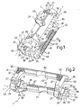
Figures 1 and 2 show two different views in perspective of a preferred embodiment of a clamp for gripping cables issuing from an electric connector, in accordance with the present invention; -
Figures 3 and 4 show, in perspective, assembly of the clamp according to the present invention to the insulating casing of an electric connector; -
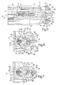
Figure 5 shows a cross section, with parts removed for clarity, of theFigure 4 electric connector; -
Figures 6 and 7 show partial side views of theFigure 5 electric connector, and the clamp in an open and closed position respectively. -
Number 1 in the accompanying drawings indicates a clamp for gripping cables 2 issuing from an electric connector 3 (shown partly). - With reference to
Figure 5 ,connector 3 comprises aninsulating casing 4 defining afront cavity 5 engaged, in use, by a complementary connector (not shown), and a number of parallel, side by side channels 6 (only one shown), which communicate withcavity 5, have respective axes A parallel to a longitudinal coupling direction ofconnector 3 to the complementary connector, and come out throughrespective openings 7 formed in a rear portion 8 ofcasing 4. -
Channels 6 house respective known maleelectric terminals 9 connected in fixed positions tocasing 4, in known manner not described in detail, and each of which comprises a blade-typeend contact portion 10 projecting insidecavity 5, and a connectingportion 11 for connection to a respective electric cable 2. - Cables 2 extend from portion 8, in a direction parallel to
respective terminals 9, throughopenings 7, and compriserespective portions 13 outsidecasing 4 and which are gripped byclamp 1. - With reference to
Figure 3 , portion 8 comprises two parallel lateral faces 14 (only one shown), from each of which project integrally a pair ofappendixes cylindrical pin 17 interposed betweenappendixes Figures 5 and 6 ) containing axes A ofchannels 6 andopenings 7. The twopins 17 are coaxial along an axis lying in plane P;appendixes 15 are located on the end edge of portion 8, are symmetrical in shape with respect to plane P, and define respective V-shaped seats 19 facingpins 17; andappendixes 16 define respective concave surfaces 20 facing and coaxial withpins 17. - With reference to the accompanying drawings,
pins 17 define a hinge, about whichclamp 1 is mounted to rotate. More specifically,clamp 1 is formed in one piece, preferably from plastic material, and comprises twojaws virtual hinge 23, which is defined by two arc-shaped portions 24 spaced apart and coaxial with each other along an axis C parallel to the axis ofpins 17.Portions 24 are housed betweenpins 17 and surfaces 20, define respective substantiallycircular seats 26 engaged radially loosely bypins 17, haveends 27 defining respective intermediate openings 28 betweenjaws jaws Figure 6 ), and a closed position (Figure 7 ) grippingportions 13 of cables 2. -
Clamp 1 also comprises anelastic parting device 30, which is interposed betweenjaws hinge 23 in a direction perpendicular to axis C, and exerts elastic thrust onjaws Device 30 comprises two elasticallydeformable portions 31, which are aligned and spaced apart in a direction parallel to axis C, are integral withportions 24, and extend fromends 27 and face openings 28 to define, together withportions 24, two elasticallydeformable rings 33 shaped symmetrically with respect to a mid-plane ofclamp 1 containing axis C. -
Portions 31 are ogival in shape, and comprise respective pairs of arc-shaped, outwardly-convex branches orblades 34 joined atrespective tips 35, which face away fromhinge 23 and at least partly engageseats 19 to keepclamp 1 in an angularly fixed reference position in whichjaws - With reference to
Figures 1, 2 and5 ,jaws lateral arms rings 33. The arms of eachjaw ends 27, are parallel to each other, and haverespective backs 39, which are at least partly knurled or ribbed for easy manual pressure by fitters. -
Jaws intermediate portions arms surfaces portions 13.Surface 42 has a triangular-section tooth 44 parallel to axis C, whilesurface 43 has twoteeth 45 parallel to axis C and defining, in between, arecess 46 complementary totooth 44 and engaged bytooth 44 whenjaws Teeth grooves 47 perpendicular to axis C, and which provide for positioning and retaining cables 2 in a direction parallel to axis C. - With reference to
Figures 6 and 7 , a conveniently click-onretaining device 49 is provided to keepjaws hooks 50, which are integral withjaw 21, define extensions ofarms 37 at opposite ends ofportion 40,face tips 35, and are defined by respectiveconvex surfaces 51 facingarms 38, and by respective flatretaining surfaces 52 facing and substantially parallel toarms 37. -
Device 49 also comprises twoseats 55, which are formed injaw 22, at opposite ends ofportion 41, are complementary tohooks 50, and have respective flat retaining surfaces 56 which rest onrespective surfaces 52 in the closed position. Surface 56 of eachseat 55 is defined by atooth 58, which engages thegap 59 betweenrelative surface 52 andrelative arm 37 in the closed position (Figure 7 ), and has a curved,convex surface 60 which slides againstsurface 51 ofrelative hook 50 when closingjaws - To fit
clamp 1 to casing 4 (Figure 3 ),rings 33 are parted slightly along axis C, making use of the flexibility of the material from whichclamp 1 is made;clamp 1 is fitted longitudinally onto portion 8;seats 26 are positioned alongpins 17; andarms portions 24 betweenpins 17 and surfaces 20, and to inserttips 35 insideseats 19. - To grip cables 2 (
Figure 7 ),jaws backs 39 in opposition to the elastic parting force ofrings 33, to slidesurfaces 60 alongsurfaces 51 and clickhooks 50 insideseats 55, andteeth 58 insidegaps 59. - In the
event device 49 does not lock properly,portions 31 springopen jaws - As will be clear from the foregoing description, the bulk produced by
clamp 1 close to portion 8 ofcasing 4 is relatively small, on account ofdevice 49 being formed in one piece withjaws jaws - Cables 2 are also clamped extremely quickly, by virtue of there being no additional retaining bodies to handle, and
jaws arms - Correct closure of
jaws device 49 andportions connector 3, and by virtue ofdevice 30springing jaws -
Clamp 1 is also relatively straightforward, in thathinge 23 anddevice 30 also provide, respectively, for fittingjaws casing 4 and keepingclamp 1 in a fixed reference position with respect tocasing 4. - Moreover, the design of
surfaces jaws - Clearly, changes may be made to clamp 1 as described herein without, however, departing from the scope of the present invention.
- In particular, as opposed to two spaced
hooks 50, one locking or retaining member may be provided, possibly located in a different position from those shown by way of example. - Alternatively, if
intermediate portions jaws end hooks 50. -
Clamp 1 may be connected tocasing 4 otherwise than as shown, e.g. by means of teeth engaging respective seats incasing 4, and/or at least one ofjaws casing 4. -
Jaws hinge 23, but still in such a manner as to rotate or translate between the open and closed positions, and/or axis C may be parallel as opposed to crosswise to cables 2. - Finally,
device 30 may comprise elastically deformable portions differing fromportions 31, and/or elastic members separate fromjaws
Claims (18)
- An electric connector (3) comprising:- an insulating casing (4), from which a number of cables (2) may issue, and- a clamp (1) designed for gripping said cables (2);said clamp (1) comprising two jaws (21, 22) movable with respect to each other between a parted open position and a closed position allowing to grip said cables (2), and fastening means (24) for fitting the clamp (1) to said insulating casing (4); retaining means (49) being provided to keep said jaws (21, 22) in said closed position and being formed in one piece with said jaws (21, 22) ;
characterized in that said clamp (1) is formed from plastic material and is directly connected via said fastening means (24) to said insulting casing (4). - An electric connector as claimed in claim 1, characterized in that said fastening means (24) and said jaws (21, 22) are located at opposite sides of the clamp (1).
- An electric connector as claimed in Claim 1 or 2, characterized in that said clamp (1) comprises a hinge (23) enabling said jaws (21, 22) to rotate between said open position and said closed position about a hinge axis (C); and elastic parting means (30) interposed between said jaws (21, 22), spaced apart from said hinge (23), and exerting elastic thrust on said jaws (21, 22) to push the jaws into said open position.
- An electric connector as claimed in Claim 3, characterized in that said hinge (23) comprises elastically deformable portions (24) forming part of said fastening means (24).
- An electric connector as claimed in Claim 3 or 4, characterized in that said elastic parting means (30) are formed in one piece with said jaws (21, 22).
- An electric connector as claimed in Claim 5, characterized in that said elastic parting means (30) and said hinge (23) together define two elastically deformable rings (33) coaxial with each other and spaced apart along said hinge axis (C); said jaws (21, 22) projecting from said rings (33).
- An electric connector as claimed in Claim 6, characterized in that each said ring (33) is symmetrical with respect to a mid-plane of the clamp (1) containing said hinge axis (C).
- An electric connector as claimed in Claim 7, characterized in that said hinge (23) comprises, in each said ring (33), a relative arc-shaped portion (24) defining a circular seat (26) having an opening (28) formed in an intermediate position between said jaws (21, 22).
- An electric connector as claimed in Claim 7 or 8, characterized in that said elastic parting means (30) comprise, for each said ring (33), a relative pair of arc-shaped branches (34) joined at a tip (35).
- An electric connector as claimed in Claim 9, characterized in that said tip (35) faces away from said hinge (23).
- An electric connector as claimed in any one of the foregoing Claims, characterized in that said retaining means (49) comprise a click-on connecting device (49).
- An electric connector as claimed in Claim 11, characterized in that said retaining means (49) comprise at least one hook (50) integral with one of said jaws (21), and at least one corresponding retaining seat (55) formed in the other of said jaws (22) and engaged by said hook (50) in said closed position.
- An electric connector as claimed in Claim 12, characterized in that said jaws (21, 22) comprise respective pairs of lateral arms (37, 38), and respective intermediate portions (40, 41) facing each other, parallel to said hinge axis (C), and for gripping said cables (2); said retaining means (49) comprising two said hooks (50) located on one of said jaws (21), at opposite ends of the relative intermediate portion (40), and two corresponding retaining seats (55) formed in the other of said jaws (22), at opposite ends of the relative intermediate portion (41).
- An electric connector as claimed in Claim 13, characterized in that at least one of said intermediate portions (40, 41) has a number of grooves (47) perpendicular to said hinge axis (C).
- An electric connector as claimed in Claim 13 or 14, characterized in that at least one of said intermediate portions (40) comprises a tooth (44) parallel to said hinge axis (C), and the other of said intermediate portions (41) comprises an elongated recess (46) engaged by said tooth (44) in said closed position.
- An electric connector as claimed in any one of the previous claim, characterized by comprising hinge means (17) for fitting said clamp (1) to said insulating casing (4) in rotary manner.
- An electric connector as claimed in Claim 16, characterized in that said insulating casing (4) comprises reference means (19) engaged at least partly by a portion (35) of said clamp (1), to keep the clamp (1) in a fixed angular position with respect to said insulating casing (4).
- An electric connector as claimed in Claim 17, characterized in that said clamp (1) comprises elastic parting means (30) interposed between said jaws (21, 22) and exerting elastic thrust on said jaws (21, 22) to push the jaws into said open position; said reference means (19) comprising at least one reference seat (19) engaged by said elastic parting means (30).
Applications Claiming Priority (2)
| Application Number | Priority Date | Filing Date | Title |
|---|---|---|---|
| IT000858A ITTO20030858A1 (en) | 2003-10-31 | 2003-10-31 | TIGHTENING ELEMENT OF OUTDOOR CABLES FROM AN ELECTRIC CONNECTOR, AND ELECTRIC CONNECTOR PROVIDED WITH THIS TIGHTENING ELEMENT. |
| PCT/EP2004/052695 WO2005043690A1 (en) | 2003-10-31 | 2004-10-28 | Clamp for gripping cables issuing from an electric connector, and electric connector featuring such a clamp |
Publications (2)
| Publication Number | Publication Date |
|---|---|
| EP1687871A1 EP1687871A1 (en) | 2006-08-09 |
| EP1687871B1 true EP1687871B1 (en) | 2008-05-28 |
Family
ID=34531940
Family Applications (1)
| Application Number | Title | Priority Date | Filing Date |
|---|---|---|---|
| EP04817393A Not-in-force EP1687871B1 (en) | 2003-10-31 | 2004-10-28 | Electric connector with a clamp for gripping cables |
Country Status (10)
| Country | Link |
|---|---|
| US (1) | US7442071B2 (en) |
| EP (1) | EP1687871B1 (en) |
| JP (1) | JP4949847B2 (en) |
| CN (1) | CN100508296C (en) |
| AT (1) | ATE397309T1 (en) |
| BR (1) | BRPI0415810A (en) |
| DE (1) | DE602004014183D1 (en) |
| ES (1) | ES2308308T3 (en) |
| IT (1) | ITTO20030858A1 (en) |
| WO (1) | WO2005043690A1 (en) |
Families Citing this family (5)
| Publication number | Priority date | Publication date | Assignee | Title |
|---|---|---|---|---|
| BR112016023747A2 (en) | 2014-04-11 | 2017-08-15 | Thomas & Betts Int Llc | laminated structure and clamp mechanism for leakage circuit indicator |
| US10516233B2 (en) * | 2017-05-10 | 2019-12-24 | Virginia Panel Corporation | Configurable strain relieve plate |
| US10290970B1 (en) * | 2018-02-08 | 2019-05-14 | Delphi Technologies, Llc | Connector with strain relief device |
| USD879041S1 (en) * | 2018-04-03 | 2020-03-24 | Electro Expo Limited | Electrical connector |
| CN110635297B (en) * | 2019-04-23 | 2021-05-18 | 中航光电科技股份有限公司 | Connector tail accessory and connector assembly |
Family Cites Families (13)
| Publication number | Priority date | Publication date | Assignee | Title |
|---|---|---|---|---|
| JPS5829584Y2 (en) * | 1978-10-27 | 1983-06-29 | 松下電器産業株式会社 | electrical connectors |
| DE3108744C2 (en) * | 1981-03-07 | 1984-03-15 | F. Wieland, Elektrische Industrie GmbH, 8600 Bamberg | Multipole electrical connector with a releasable strain relief device |
| JPS61206276U (en) * | 1985-06-14 | 1986-12-26 | ||
| JPH0534674U (en) * | 1991-10-14 | 1993-05-07 | ヒロセ電機株式会社 | Grommet structure |
| AU667541B2 (en) * | 1992-07-03 | 1996-03-28 | Amphenol Corporation | Cord grip arrangement |
| JP2964446B2 (en) * | 1994-11-22 | 1999-10-18 | 矢崎総業株式会社 | ID connector |
| JP3402020B2 (en) * | 1995-10-05 | 2003-04-28 | 住友電装株式会社 | Connector with wire cover |
| JPH09306624A (en) * | 1996-05-17 | 1997-11-28 | Texas Instr Japan Ltd | Socket |
| US5961351A (en) * | 1996-08-21 | 1999-10-05 | Hon Hai Precision Ind. Co., Ltd. | Universal serial Bus B-type plug connector |
| JPH10144391A (en) * | 1996-11-12 | 1998-05-29 | Olympus Optical Co Ltd | Memory card fitting apparatus |
| CA2261307A1 (en) * | 1997-05-22 | 1998-11-26 | Mark R. Drane | Cable splice closure |
| US5934931A (en) * | 1997-08-27 | 1999-08-10 | Leviton Manufacturing Co., Inc. | Strain-relief system for a folding plug and connector system |
| US6126478A (en) * | 1998-07-01 | 2000-10-03 | Hubbell Incorporated | Wiring device with gripping of individual conductors |
-
2003
- 2003-10-31 IT IT000858A patent/ITTO20030858A1/en unknown
-
2004
- 2004-10-28 CN CNB2004800355906A patent/CN100508296C/en not_active Expired - Fee Related
- 2004-10-28 EP EP04817393A patent/EP1687871B1/en not_active Not-in-force
- 2004-10-28 WO PCT/EP2004/052695 patent/WO2005043690A1/en active IP Right Grant
- 2004-10-28 DE DE602004014183T patent/DE602004014183D1/en active Active
- 2004-10-28 US US10/577,515 patent/US7442071B2/en not_active Expired - Fee Related
- 2004-10-28 ES ES04817393T patent/ES2308308T3/en active Active
- 2004-10-28 BR BRPI0415810-5A patent/BRPI0415810A/en not_active IP Right Cessation
- 2004-10-28 AT AT04817393T patent/ATE397309T1/en not_active IP Right Cessation
- 2004-10-28 JP JP2006537302A patent/JP4949847B2/en not_active Expired - Fee Related
Also Published As
| Publication number | Publication date |
|---|---|
| DE602004014183D1 (en) | 2008-07-10 |
| US20070281539A1 (en) | 2007-12-06 |
| WO2005043690A1 (en) | 2005-05-12 |
| JP4949847B2 (en) | 2012-06-13 |
| ES2308308T3 (en) | 2008-12-01 |
| BRPI0415810A (en) | 2006-12-26 |
| JP2007510264A (en) | 2007-04-19 |
| CN1886867A (en) | 2006-12-27 |
| ATE397309T1 (en) | 2008-06-15 |
| CN100508296C (en) | 2009-07-01 |
| ITTO20030858A1 (en) | 2005-05-01 |
| EP1687871A1 (en) | 2006-08-09 |
| US7442071B2 (en) | 2008-10-28 |
Similar Documents
| Publication | Publication Date | Title |
|---|---|---|
| JP3754086B2 (en) | Electrical connector with pivot lock | |
| EP0632529B1 (en) | Spring clamp connector | |
| US5348494A (en) | Adapter/connector shell assembly with unisex hardware | |
| US4200350A (en) | Toolless retention system | |
| KR100227170B1 (en) | Electrical connector with terminal position assurance device and guide means for a mating connector | |
| US5774980A (en) | Method of attaching a device to an electrical cord | |
| EP0425130A2 (en) | Electrical connector with hinged secondary lock | |
| JPH0237663B2 (en) | ||
| US10535951B2 (en) | Plug connector and method for producing a plug connection | |
| EP0954060A3 (en) | Electrical connector with deflectable secondary locking | |
| EP1687871B1 (en) | Electric connector with a clamp for gripping cables | |
| EP1629571B1 (en) | A contact-holder unit for an electrical connection socket/plug | |
| US5324209A (en) | Adapter/connector shell assembly with unisex features | |
| US4257666A (en) | Plug | |
| US4641899A (en) | Multi-part electrical connector assembly | |
| US7326072B2 (en) | Connection element for the electrically conductive connection to the lamp holder of a main headlamp | |
| JPS5944751B2 (en) | Connectors and electrical connection methods between connectors | |
| CN112886317A (en) | Connector with a locking member | |
| JP2916630B2 (en) | Power distribution unit | |
| EP1434312B1 (en) | Connector for electrical systems | |
| EP1955417B1 (en) | Electrical connector for mounting in a panel cutout | |
| JPH10134918A (en) | Magnet type electrical wire connecting adapter | |
| US20230129127A1 (en) | Plug-in connector and plug-in connector arrangement | |
| US4778398A (en) | Safety cover assembly for end connectors | |
| EP0911911A1 (en) | Connector housing with latch arm |
Legal Events
| Date | Code | Title | Description |
|---|---|---|---|
| PUAI | Public reference made under article 153(3) epc to a published international application that has entered the european phase |
Free format text: ORIGINAL CODE: 0009012 |
|
| 17P | Request for examination filed |
Effective date: 20060531 |
|
| AK | Designated contracting states |
Kind code of ref document: A1 Designated state(s): AT BE BG CH CY CZ DE DK EE ES FI FR GB GR HU IE IT LI LU MC NL PL PT RO SE SI SK TR |
|
| 17Q | First examination report despatched |
Effective date: 20060918 |
|
| DAX | Request for extension of the european patent (deleted) | ||
| 17Q | First examination report despatched |
Effective date: 20060918 |
|
| GRAP | Despatch of communication of intention to grant a patent |
Free format text: ORIGINAL CODE: EPIDOSNIGR1 |
|
| RTI1 | Title (correction) |
Free format text: ELECTRIC CONNECTOR WITH A CLAMP FOR GRIPPING CABLES |
|
| GRAS | Grant fee paid |
Free format text: ORIGINAL CODE: EPIDOSNIGR3 |
|
| GRAA | (expected) grant |
Free format text: ORIGINAL CODE: 0009210 |
|
| STAA | Information on the status of an ep patent application or granted ep patent |
Free format text: STATUS: THE PATENT HAS BEEN GRANTED |
|
| AK | Designated contracting states |
Kind code of ref document: B1 Designated state(s): AT BE BG CH CY CZ DE DK EE ES FI FR GB GR HU IE IT LI LU MC NL PL PT RO SE SI SK TR |
|
| REG | Reference to a national code |
Ref country code: GB Ref legal event code: FG4D |
|
| REG | Reference to a national code |
Ref country code: CH Ref legal event code: EP |
|
| REF | Corresponds to: |
Ref document number: 602004014183 Country of ref document: DE Date of ref document: 20080710 Kind code of ref document: P |
|
| REG | Reference to a national code |
Ref country code: IE Ref legal event code: FG4D |
|
| PG25 | Lapsed in a contracting state [announced via postgrant information from national office to epo] |
Ref country code: SI Free format text: LAPSE BECAUSE OF FAILURE TO SUBMIT A TRANSLATION OF THE DESCRIPTION OR TO PAY THE FEE WITHIN THE PRESCRIBED TIME-LIMIT Effective date: 20080528 |
|
| PG25 | Lapsed in a contracting state [announced via postgrant information from national office to epo] |
Ref country code: FI Free format text: LAPSE BECAUSE OF FAILURE TO SUBMIT A TRANSLATION OF THE DESCRIPTION OR TO PAY THE FEE WITHIN THE PRESCRIBED TIME-LIMIT Effective date: 20080528 |
|
| PG25 | Lapsed in a contracting state [announced via postgrant information from national office to epo] |
Ref country code: AT Free format text: LAPSE BECAUSE OF FAILURE TO SUBMIT A TRANSLATION OF THE DESCRIPTION OR TO PAY THE FEE WITHIN THE PRESCRIBED TIME-LIMIT Effective date: 20080528 Ref country code: NL Free format text: LAPSE BECAUSE OF FAILURE TO SUBMIT A TRANSLATION OF THE DESCRIPTION OR TO PAY THE FEE WITHIN THE PRESCRIBED TIME-LIMIT Effective date: 20080528 |
|
| NLV1 | Nl: lapsed or annulled due to failure to fulfill the requirements of art. 29p and 29m of the patents act | ||
| REG | Reference to a national code |
Ref country code: ES Ref legal event code: FG2A Ref document number: 2308308 Country of ref document: ES Kind code of ref document: T3 |
|
| PG25 | Lapsed in a contracting state [announced via postgrant information from national office to epo] |
Ref country code: PT Free format text: LAPSE BECAUSE OF FAILURE TO SUBMIT A TRANSLATION OF THE DESCRIPTION OR TO PAY THE FEE WITHIN THE PRESCRIBED TIME-LIMIT Effective date: 20081028 Ref country code: SE Free format text: LAPSE BECAUSE OF FAILURE TO SUBMIT A TRANSLATION OF THE DESCRIPTION OR TO PAY THE FEE WITHIN THE PRESCRIBED TIME-LIMIT Effective date: 20080828 Ref country code: DK Free format text: LAPSE BECAUSE OF FAILURE TO SUBMIT A TRANSLATION OF THE DESCRIPTION OR TO PAY THE FEE WITHIN THE PRESCRIBED TIME-LIMIT Effective date: 20080528 Ref country code: CZ Free format text: LAPSE BECAUSE OF FAILURE TO SUBMIT A TRANSLATION OF THE DESCRIPTION OR TO PAY THE FEE WITHIN THE PRESCRIBED TIME-LIMIT Effective date: 20080528 |
|
| PG25 | Lapsed in a contracting state [announced via postgrant information from national office to epo] |
Ref country code: RO Free format text: LAPSE BECAUSE OF FAILURE TO SUBMIT A TRANSLATION OF THE DESCRIPTION OR TO PAY THE FEE WITHIN THE PRESCRIBED TIME-LIMIT Effective date: 20080528 Ref country code: SK Free format text: LAPSE BECAUSE OF FAILURE TO SUBMIT A TRANSLATION OF THE DESCRIPTION OR TO PAY THE FEE WITHIN THE PRESCRIBED TIME-LIMIT Effective date: 20080528 Ref country code: BE Free format text: LAPSE BECAUSE OF FAILURE TO SUBMIT A TRANSLATION OF THE DESCRIPTION OR TO PAY THE FEE WITHIN THE PRESCRIBED TIME-LIMIT Effective date: 20080528 |
|
| PLBE | No opposition filed within time limit |
Free format text: ORIGINAL CODE: 0009261 |
|
| STAA | Information on the status of an ep patent application or granted ep patent |
Free format text: STATUS: NO OPPOSITION FILED WITHIN TIME LIMIT |
|
| PG25 | Lapsed in a contracting state [announced via postgrant information from national office to epo] |
Ref country code: BG Free format text: LAPSE BECAUSE OF FAILURE TO SUBMIT A TRANSLATION OF THE DESCRIPTION OR TO PAY THE FEE WITHIN THE PRESCRIBED TIME-LIMIT Effective date: 20080828 Ref country code: EE Free format text: LAPSE BECAUSE OF FAILURE TO SUBMIT A TRANSLATION OF THE DESCRIPTION OR TO PAY THE FEE WITHIN THE PRESCRIBED TIME-LIMIT Effective date: 20080528 |
|
| 26N | No opposition filed |
Effective date: 20090303 |
|
| PG25 | Lapsed in a contracting state [announced via postgrant information from national office to epo] |
Ref country code: MC Free format text: LAPSE BECAUSE OF NON-PAYMENT OF DUE FEES Effective date: 20081031 |
|
| REG | Reference to a national code |
Ref country code: CH Ref legal event code: PL |
|
| GBPC | Gb: european patent ceased through non-payment of renewal fee |
Effective date: 20081028 |
|
| PG25 | Lapsed in a contracting state [announced via postgrant information from national office to epo] |
Ref country code: LI Free format text: LAPSE BECAUSE OF NON-PAYMENT OF DUE FEES Effective date: 20081031 Ref country code: CH Free format text: LAPSE BECAUSE OF NON-PAYMENT OF DUE FEES Effective date: 20081031 Ref country code: IE Free format text: LAPSE BECAUSE OF NON-PAYMENT OF DUE FEES Effective date: 20081028 |
|
| PG25 | Lapsed in a contracting state [announced via postgrant information from national office to epo] |
Ref country code: GB Free format text: LAPSE BECAUSE OF NON-PAYMENT OF DUE FEES Effective date: 20081028 |
|
| PG25 | Lapsed in a contracting state [announced via postgrant information from national office to epo] |
Ref country code: PL Free format text: LAPSE BECAUSE OF FAILURE TO SUBMIT A TRANSLATION OF THE DESCRIPTION OR TO PAY THE FEE WITHIN THE PRESCRIBED TIME-LIMIT Effective date: 20080528 |
|
| PG25 | Lapsed in a contracting state [announced via postgrant information from national office to epo] |
Ref country code: LU Free format text: LAPSE BECAUSE OF NON-PAYMENT OF DUE FEES Effective date: 20081028 Ref country code: CY Free format text: LAPSE BECAUSE OF FAILURE TO SUBMIT A TRANSLATION OF THE DESCRIPTION OR TO PAY THE FEE WITHIN THE PRESCRIBED TIME-LIMIT Effective date: 20080528 Ref country code: HU Free format text: LAPSE BECAUSE OF FAILURE TO SUBMIT A TRANSLATION OF THE DESCRIPTION OR TO PAY THE FEE WITHIN THE PRESCRIBED TIME-LIMIT Effective date: 20081129 |
|
| PG25 | Lapsed in a contracting state [announced via postgrant information from national office to epo] |
Ref country code: TR Free format text: LAPSE BECAUSE OF FAILURE TO SUBMIT A TRANSLATION OF THE DESCRIPTION OR TO PAY THE FEE WITHIN THE PRESCRIBED TIME-LIMIT Effective date: 20080528 |
|
| PG25 | Lapsed in a contracting state [announced via postgrant information from national office to epo] |
Ref country code: GR Free format text: LAPSE BECAUSE OF FAILURE TO SUBMIT A TRANSLATION OF THE DESCRIPTION OR TO PAY THE FEE WITHIN THE PRESCRIBED TIME-LIMIT Effective date: 20080829 |
|
| REG | Reference to a national code |
Ref country code: FR Ref legal event code: CA |
|
| REG | Reference to a national code |
Ref country code: FR Ref legal event code: TP |
|
| REG | Reference to a national code |
Ref country code: FR Ref legal event code: GC |
|
| REG | Reference to a national code |
Ref country code: DE Ref legal event code: R081 Ref document number: 602004014183 Country of ref document: DE Owner name: FCI AUTOMOTIVE HOLDING, FR Free format text: FORMER OWNER: FCI, VERSAILLES, FR Effective date: 20120419 Ref country code: DE Ref legal event code: R081 Ref document number: 602004014183 Country of ref document: DE Owner name: DELPHI INTERNATIONAL OPERATIONS LUXEMBOURG S.A, LU Free format text: FORMER OWNER: FCI, VERSAILLES, FR Effective date: 20120419 |
|
| REG | Reference to a national code |
Ref country code: DE Ref legal event code: R081 Ref document number: 602004014183 Country of ref document: DE Owner name: DELPHI INTERNATIONAL OPERATIONS LUXEMBOURG S.A, LU Free format text: FORMER OWNER: FCI, GUYANCOURT, FR Effective date: 20120629 |
|
| PGFP | Annual fee paid to national office [announced via postgrant information from national office to epo] |
Ref country code: DE Payment date: 20131029 Year of fee payment: 10 Ref country code: FR Payment date: 20131017 Year of fee payment: 10 |
|
| PGFP | Annual fee paid to national office [announced via postgrant information from national office to epo] |
Ref country code: IT Payment date: 20131024 Year of fee payment: 10 Ref country code: ES Payment date: 20131028 Year of fee payment: 10 |
|
| REG | Reference to a national code |
Ref country code: FR Ref legal event code: TP Owner name: DELPHI INTERNATIONAL OPERATIONS LUXEMBOURG S.A, LU Effective date: 20140715 |
|
| REG | Reference to a national code |
Ref country code: DE Ref legal event code: R082 Ref document number: 602004014183 Country of ref document: DE Representative=s name: BARDEHLE PAGENBERG PARTNERSCHAFT MBB PATENTANW, DE |
|
| REG | Reference to a national code |
Ref country code: DE Ref legal event code: R081 Ref document number: 602004014183 Country of ref document: DE Owner name: DELPHI INTERNATIONAL OPERATIONS LUXEMBOURG S.A, LU Free format text: FORMER OWNER: FCI AUTOMOTIVE HOLDING, GUYANCOURT, FR Effective date: 20141106 Ref country code: DE Ref legal event code: R082 Ref document number: 602004014183 Country of ref document: DE Representative=s name: BARDEHLE PAGENBERG PARTNERSCHAFT MBB PATENTANW, DE Effective date: 20141106 |
|
| REG | Reference to a national code |
Ref country code: DE Ref legal event code: R119 Ref document number: 602004014183 Country of ref document: DE |
|
| PG25 | Lapsed in a contracting state [announced via postgrant information from national office to epo] |
Ref country code: DE Free format text: LAPSE BECAUSE OF NON-PAYMENT OF DUE FEES Effective date: 20150501 |
|
| REG | Reference to a national code |
Ref country code: FR Ref legal event code: ST Effective date: 20150630 |
|
| PG25 | Lapsed in a contracting state [announced via postgrant information from national office to epo] |
Ref country code: IT Free format text: LAPSE BECAUSE OF NON-PAYMENT OF DUE FEES Effective date: 20141028 Ref country code: FR Free format text: LAPSE BECAUSE OF NON-PAYMENT OF DUE FEES Effective date: 20141031 |
|
| REG | Reference to a national code |
Ref country code: ES Ref legal event code: FD2A Effective date: 20151126 |
|
| PG25 | Lapsed in a contracting state [announced via postgrant information from national office to epo] |
Ref country code: ES Free format text: LAPSE BECAUSE OF NON-PAYMENT OF DUE FEES Effective date: 20141029 |