EP1434312B1 - Connector for electrical systems - Google Patents
Connector for electrical systems Download PDFInfo
- Publication number
- EP1434312B1 EP1434312B1 EP03026320A EP03026320A EP1434312B1 EP 1434312 B1 EP1434312 B1 EP 1434312B1 EP 03026320 A EP03026320 A EP 03026320A EP 03026320 A EP03026320 A EP 03026320A EP 1434312 B1 EP1434312 B1 EP 1434312B1
- Authority
- EP
- European Patent Office
- Prior art keywords
- anchoring
- casing
- connector
- lever
- spring
- Prior art date
- Legal status (The legal status is an assumption and is not a legal conclusion. Google has not performed a legal analysis and makes no representation as to the accuracy of the status listed.)
- Expired - Lifetime
Links
Images


Classifications
-
- H—ELECTRICITY
- H01—ELECTRIC ELEMENTS
- H01R—ELECTRICALLY-CONDUCTIVE CONNECTIONS; STRUCTURAL ASSOCIATIONS OF A PLURALITY OF MUTUALLY-INSULATED ELECTRICAL CONNECTING ELEMENTS; COUPLING DEVICES; CURRENT COLLECTORS
- H01R13/00—Details of coupling devices of the kinds covered by groups H01R12/70 or H01R24/00 - H01R33/00
- H01R13/62—Means for facilitating engagement or disengagement of coupling parts or for holding them in engagement
- H01R13/629—Additional means for facilitating engagement or disengagement of coupling parts, e.g. aligning or guiding means, levers, gas pressure electrical locking indicators, manufacturing tolerances
- H01R13/62933—Comprising exclusively pivoting lever
- H01R13/62966—Comprising two pivoting levers
Definitions
- the present invention relates to a connector for electrical systems.
- EP-A-0405168 discloses an electric connector provided with locking handles having spring members that provide a looking force.
- US-6658162 discloses an electric plug and socket connector provided with locking handles having spring members arranged in side pockets in order to simply the construction.
- the aim of the present invention is to provide a connector that is improved with respect to currently known connectors.
- An object of the invention is to provide a connector that is simple and reliable in use.
- Another object of the invention is to provide a connector that is constituted by a small number of components, fully to the benefit of production economy.
- a connector according to the invention comprises an inline casing 2 having pins 4 and that can be coupled to a fixed flush-mount casing 3 having receptacles 5.
- the inline casing can be coupled to the fixed casing by an anchoring-lever connection, which is constituted by an anchoring lever 6 that is pivoted to the fixed casing 3 at a pivot 11 and is suitable to engage a pair of studs 7 that are associated with the inline casing 2.
- an anchoring-lever connection which is constituted by an anchoring lever 6 that is pivoted to the fixed casing 3 at a pivot 11 and is suitable to engage a pair of studs 7 that are associated with the inline casing 2.
- the anchoring lever 6 is monolithic and has reference members 8 and 9 that are adapted to retain a contoured spring 10, which acts as a device for anchoring the inline casing 2 to the stud 7.
- the spring 10 has been designed with a closed contour in order to provide better elasticity and stability over time.
- the reference members 9, provided at a rectangular opening 13, are useful in the clinching operation for retaining the contoured spring 10 in position.
- the reference member 8 prevents the contoured spring 10 from undergoing, upon anchoring, an inward flexing or movement.
- the anchoring lever 6 has a handle 14 that can be gripped by the operator in order to close or open the connector.
- the connector has receptacles and pins, which both have, in their rear region, a cable clamping system constituted by a screw 15 that does not act directly on the cable but acts by means of a blade 16 that is inserted in the connecting seat and distributes all its clamping force on the cable in the seat.
- the blade 16 has a suitable shape, designed so that it can remain in its seat by virtue of a hole 17 that is provided at the seat and a tab 18 that is provided on the blade itself.
- the anchoring hole 17 lies opposite the screw 15 in order to increase as much as possible the length of the spring and thus make it very flexible, with no risk of yielding.
- the blade 16 is always in a fixed cable insertion position when the screw 15 is unscrewed.
- the blade 16 can be inserted with a snap action in its seat, facilitating its assembly in the clamping system.
- Figure 8 illustrates a connector 101 provided with two anchoring levers 106.
- the connector according to this further aspect of the invention comprises an inline casing 102, having pins and that can be coupled to a fixed flush-mount casing 103, which has the receptacles.
- the inline casing 102 can be coupled to the fixed casing 103 by means of an anchoring-lever connection that is constituted by two anchoring levers 106, which are pivoted to the fixed casing 103 in respective pairs of pivots 111 and engage respective pairs of studs 107 that are associated with the inline casing 102.
- Each anchoring lever 106 is monolithic and is substantially similar to the lever 6 described above.
Description
- The present invention relates to a connector for electrical systems.
-
EP-A-0405168 discloses an electric connector provided with locking handles having spring members that provide a looking force. -
US-6658162 discloses an electric plug and socket connector provided with locking handles having spring members arranged in side pockets in order to simply the construction. - The aim of the present invention is to provide a connector that is improved with respect to currently known connectors.
- An object of the invention is to provide a connector that is simple and reliable in use.
- Another object of the invention is to provide a connector that is constituted by a small number of components, fully to the benefit of production economy.
- That aim and those and other objects that will become better apparent hereinafter are achieved by a connector for electrical systems as claimed in the appended claims.
- Further characteristics and advantages of the invention will become better apparent from the description of preferred but not exclusive embodiments thereof, illustrated by way of non-limitative example in the accompanying drawings, wherein:
-
Figure 1 is a perspective view of the connector according to the invention; -
Figure 2 is a longitudinal sectional view of a pin; -
Figure 3 is a longitudinal sectional view of a receptacle; -
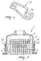
Figure 4 is a perspective view of the anchoring lever; -
Figure 5 is a partial perspective view of the anchoring lever for a single-lever connector; -
Figure 6 is a front view of the contoured spring of the anchoring lever; -
Figure 7 is a sectional front elevation view of the connector according to the invention; -
Figure 8 is a perspective view of the connector according to a further aspect of the invention, provided with two anchoring levers. - With reference to the cited figures, a connector according to the invention, generally designated by the reference numeral 1, comprises an
inline casing 2 havingpins 4 and that can be coupled to a fixed flush-mount casing 3 havingreceptacles 5. - According to the invention, the inline casing can be coupled to the fixed casing by an anchoring-lever connection, which is constituted by an
anchoring lever 6 that is pivoted to the fixedcasing 3 at apivot 11 and is suitable to engage a pair ofstuds 7 that are associated with theinline casing 2. - The
anchoring lever 6 is monolithic and hasreference members contoured spring 10, which acts as a device for anchoring theinline casing 2 to thestud 7. - The
spring 10 has been designed with a closed contour in order to provide better elasticity and stability over time. - In the coupling region there is a
cusp 12 that ensures that the engagement with thepivot 11 is maintained even in critical conditions, for example in the presence of vibrations or impacts. - The
reference members 9, provided at arectangular opening 13, are useful in the clinching operation for retaining thecontoured spring 10 in position. - The
reference member 8 prevents the contouredspring 10 from undergoing, upon anchoring, an inward flexing or movement. - The
anchoring lever 6 has ahandle 14 that can be gripped by the operator in order to close or open the connector. - The connector has receptacles and pins, which both have, in their rear region, a cable clamping system constituted by a
screw 15 that does not act directly on the cable but acts by means of ablade 16 that is inserted in the connecting seat and distributes all its clamping force on the cable in the seat. - The
blade 16 has a suitable shape, designed so that it can remain in its seat by virtue of ahole 17 that is provided at the seat and atab 18 that is provided on the blade itself. - The
anchoring hole 17 lies opposite thescrew 15 in order to increase as much as possible the length of the spring and thus make it very flexible, with no risk of yielding. - By way of its particular configuration, the
blade 16 is always in a fixed cable insertion position when thescrew 15 is unscrewed. - The
blade 16 can be inserted with a snap action in its seat, facilitating its assembly in the clamping system. -
Figure 8 illustrates aconnector 101 provided with twoanchoring levers 106. - More particularly, similarly to connector 1, the connector according to this further aspect of the invention, generally designated by the
reference numeral 101, comprises aninline casing 102, having pins and that can be coupled to a fixed flush-mount casing 103, which has the receptacles. - According to the invention, the
inline casing 102 can be coupled to the fixed casing 103 by means of an anchoring-lever connection that is constituted by twoanchoring levers 106, which are pivoted to the fixed casing 103 in respective pairs ofpivots 111 and engage respective pairs ofstuds 107 that are associated with theinline casing 102. - Each
anchoring lever 106 is monolithic and is substantially similar to thelever 6 described above. - In practice It has been found that the invention achieves the intended aim and objects, a connector having been provided which has a locking and release system of the anchoring-lever type that is quick and easy.
Claims (3)
- A connector for electrical systems, comprising a first casing (2) that comprises pins (4) and can be coupled to a second casing (3) that comprises receptacles (5), said first casing (2) can be coupled to the second casing (3) by means of an anchoring-lever connection constituted by an anchoring lever (6) that is pivoted to one of the casings (2, 3) and is adapted to engage two studs (7) that are associated with the other casing (2, 3);
said anchoring lever (6) is monolithic;
said anchoring lever (6) comprises reference members (8, 9) retaining a contoured spring (10), which provides anchoring to the stud (7) of the associated casing;
characterized in that said spring (10) has a closed contour thereby providing greater elasticity and stability over time;
said spring (10) has a cusp (12) in a coupling region, said cusp (12) being adapted to ensure that the engagement with the pivot is maintained even in critical conditions, for example in the presence of vibrations or impacts;
a reference member (9), is formed at a rectangular opening (13), for the clinching operation for retaining said contoured spring (10) in position;
a reference member (8) ensures that said contoured spring (10) does not flex or move inward upon anchoring. - The connector according to claim 1, characterized in that said anchoring lever (6) has a handle (14) that can be gripped by the operator in order to close or open the connector.
- The connector according to claim 1 characterized in that it comprises two anchoring levers (6).
Applications Claiming Priority (2)
| Application Number | Priority Date | Filing Date | Title |
|---|---|---|---|
| ITMI20022742 ITMI20022742A1 (en) | 2002-12-23 | 2002-12-23 | CONNECTOR FOR ELECTRICAL SYSTEMS |
| ITMI20022742 | 2002-12-23 |
Publications (3)
| Publication Number | Publication Date |
|---|---|
| EP1434312A2 EP1434312A2 (en) | 2004-06-30 |
| EP1434312A3 EP1434312A3 (en) | 2004-09-29 |
| EP1434312B1 true EP1434312B1 (en) | 2012-08-22 |
Family
ID=32448927
Family Applications (1)
| Application Number | Title | Priority Date | Filing Date |
|---|---|---|---|
| EP03026320A Expired - Lifetime EP1434312B1 (en) | 2002-12-23 | 2003-11-17 | Connector for electrical systems |
Country Status (2)
| Country | Link |
|---|---|
| EP (1) | EP1434312B1 (en) |
| IT (1) | ITMI20022742A1 (en) |
Families Citing this family (2)
| Publication number | Priority date | Publication date | Assignee | Title |
|---|---|---|---|---|
| DE202005005548U1 (en) * | 2005-04-08 | 2006-08-17 | Weidmüller Interface GmbH & Co. KG | With a bow-shaped wire protection spring provided electrical contact element |
| DE102008059583A1 (en) | 2008-11-28 | 2010-06-02 | Lapp Engineering & Co. | Zinc die-cast housing for a connector |
Citations (3)
| Publication number | Priority date | Publication date | Assignee | Title |
|---|---|---|---|---|
| DE1656714U (en) * | 1953-03-23 | 1953-06-03 | Telefonbau & Normalzeit Gmbh | TERMINAL BAR. |
| US5658162A (en) * | 1995-03-10 | 1997-08-19 | Harting Elektronik Gmbh | Electric plug and socket connector |
| EP1345291A1 (en) * | 2002-03-06 | 2003-09-17 | WIELAND ELECTRIC GmbH | Electrical connector |
Family Cites Families (4)
| Publication number | Priority date | Publication date | Assignee | Title |
|---|---|---|---|---|
| US4401357A (en) * | 1980-05-12 | 1983-08-30 | Echlin Inc. | Electrical connectors having insert spring, cable clip and contacts with pressure strips |
| DE8135107U1 (en) * | 1981-12-02 | 1982-04-29 | Karl Lumberg GmbH & Co, 5885 Schalksmühle | Socket for a miniature relay |
| DE8908016U1 (en) | 1989-06-30 | 1989-08-31 | Hts-Elektrotechnik Gmbh, 5206 Neunkirchen-Seelscheid, De | |
| DE10120846A1 (en) * | 2001-04-27 | 2002-11-28 | Wieland Electric Gmbh | Electrical connector |
-
2002
- 2002-12-23 IT ITMI20022742 patent/ITMI20022742A1/en unknown
-
2003
- 2003-11-17 EP EP03026320A patent/EP1434312B1/en not_active Expired - Lifetime
Patent Citations (3)
| Publication number | Priority date | Publication date | Assignee | Title |
|---|---|---|---|---|
| DE1656714U (en) * | 1953-03-23 | 1953-06-03 | Telefonbau & Normalzeit Gmbh | TERMINAL BAR. |
| US5658162A (en) * | 1995-03-10 | 1997-08-19 | Harting Elektronik Gmbh | Electric plug and socket connector |
| EP1345291A1 (en) * | 2002-03-06 | 2003-09-17 | WIELAND ELECTRIC GmbH | Electrical connector |
Also Published As
| Publication number | Publication date |
|---|---|
| EP1434312A2 (en) | 2004-06-30 |
| ITMI20022742A1 (en) | 2004-06-24 |
| EP1434312A3 (en) | 2004-09-29 |
Similar Documents
| Publication | Publication Date | Title |
|---|---|---|
| EP2321879B1 (en) | Locking power connector apparatus | |
| US9531126B2 (en) | Electrical receptacle with locking feature | |
| US10547145B2 (en) | Electric receptacle with locking feature | |
| US7128595B2 (en) | Electrical connector with positive lock | |
| US7351117B1 (en) | Electrical connector assembly having pre-staging and final staging contact configurations | |
| US4913667A (en) | Connector system with replaceable plugs | |
| US7785134B2 (en) | Contact terminal for conductors | |
| EP2826107B1 (en) | Electrical plug retainer outlet | |
| US9929510B2 (en) | Locking power connector apparatus | |
| US8790129B1 (en) | User configurable connector | |
| US10348006B2 (en) | Distribution block and din rail release mechanism | |
| US8444429B2 (en) | Unlocking device, connector device, and connector | |
| US6059602A (en) | Shroud for electrical connector | |
| EP2240983B1 (en) | Locking electrical receptacle | |
| EP1434312B1 (en) | Connector for electrical systems | |
| US6966790B2 (en) | Lockable electrical plug and socket connection | |
| US10608377B2 (en) | Electrical plug connection | |
| JP4949847B2 (en) | Clamp for holding a cable extending from the electrical connector, and electrical connector provided with the clamp | |
| JPS647591Y2 (en) | ||
| GB2522840B (en) | Improvements in or relating to electrical connection arrangements | |
| KR20150109140A (en) | Flexible flat cable connector | |
| US9147946B1 (en) | Electrical cable connector | |
| US2975393A (en) | Electrical contact block | |
| KR20050027914A (en) | Connector having an interlocking system | |
| EP3590154A2 (en) | Quick coupling system in cee norm plugs and sockets |
Legal Events
| Date | Code | Title | Description |
|---|---|---|---|
| PUAI | Public reference made under article 153(3) epc to a published international application that has entered the european phase |
Free format text: ORIGINAL CODE: 0009012 |
|
| AK | Designated contracting states |
Kind code of ref document: A2 Designated state(s): AT BE BG CH CY CZ DE DK EE ES FI FR GB GR HU IE IT LI LU MC NL PT RO SE SI SK TR |
|
| AX | Request for extension of the european patent |
Extension state: AL LT LV MK |
|
| PUAL | Search report despatched |
Free format text: ORIGINAL CODE: 0009013 |
|
| AK | Designated contracting states |
Kind code of ref document: A3 Designated state(s): AT BE BG CH CY CZ DE DK EE ES FI FR GB GR HU IE IT LI LU MC NL PT RO SE SI SK TR |
|
| AX | Request for extension of the european patent |
Extension state: AL LT LV MK |
|
| 17P | Request for examination filed |
Effective date: 20041111 |
|
| AKX | Designation fees paid |
Designated state(s): AT BE BG CH CY CZ DE DK EE ES FI FR GB GR HU IE IT LI LU MC NL PT RO SE SI SK TR |
|
| 17Q | First examination report despatched |
Effective date: 20110314 |
|
| GRAP | Despatch of communication of intention to grant a patent |
Free format text: ORIGINAL CODE: EPIDOSNIGR1 |
|
| GRAS | Grant fee paid |
Free format text: ORIGINAL CODE: EPIDOSNIGR3 |
|
| GRAA | (expected) grant |
Free format text: ORIGINAL CODE: 0009210 |
|
| AK | Designated contracting states |
Kind code of ref document: B1 Designated state(s): AT BE BG CH CY CZ DE DK EE ES FI FR GB GR HU IE IT LI LU MC NL PT RO SE SI SK TR |
|
| REG | Reference to a national code |
Ref country code: GB Ref legal event code: FG4D |
|
| REG | Reference to a national code |
Ref country code: CH Ref legal event code: EP |
|
| REG | Reference to a national code |
Ref country code: IE Ref legal event code: FG4D |
|
| REG | Reference to a national code |
Ref country code: AT Ref legal event code: REF Ref document number: 572383 Country of ref document: AT Kind code of ref document: T Effective date: 20120915 |
|
| REG | Reference to a national code |
Ref country code: DE Ref legal event code: R096 Ref document number: 60341875 Country of ref document: DE Effective date: 20121018 |
|
| REG | Reference to a national code |
Ref country code: NL Ref legal event code: VDEP Effective date: 20120822 |
|
| REG | Reference to a national code |
Ref country code: AT Ref legal event code: MK05 Ref document number: 572383 Country of ref document: AT Kind code of ref document: T Effective date: 20120822 |
|
| PG25 | Lapsed in a contracting state [announced via postgrant information from national office to epo] |
Ref country code: AT Free format text: LAPSE BECAUSE OF FAILURE TO SUBMIT A TRANSLATION OF THE DESCRIPTION OR TO PAY THE FEE WITHIN THE PRESCRIBED TIME-LIMIT Effective date: 20120822 Ref country code: FI Free format text: LAPSE BECAUSE OF FAILURE TO SUBMIT A TRANSLATION OF THE DESCRIPTION OR TO PAY THE FEE WITHIN THE PRESCRIBED TIME-LIMIT Effective date: 20120822 Ref country code: CY Free format text: LAPSE BECAUSE OF FAILURE TO SUBMIT A TRANSLATION OF THE DESCRIPTION OR TO PAY THE FEE WITHIN THE PRESCRIBED TIME-LIMIT Effective date: 20120822 |
|
| PG25 | Lapsed in a contracting state [announced via postgrant information from national office to epo] |
Ref country code: BE Free format text: LAPSE BECAUSE OF FAILURE TO SUBMIT A TRANSLATION OF THE DESCRIPTION OR TO PAY THE FEE WITHIN THE PRESCRIBED TIME-LIMIT Effective date: 20120822 Ref country code: PT Free format text: LAPSE BECAUSE OF FAILURE TO SUBMIT A TRANSLATION OF THE DESCRIPTION OR TO PAY THE FEE WITHIN THE PRESCRIBED TIME-LIMIT Effective date: 20121224 Ref country code: GR Free format text: LAPSE BECAUSE OF FAILURE TO SUBMIT A TRANSLATION OF THE DESCRIPTION OR TO PAY THE FEE WITHIN THE PRESCRIBED TIME-LIMIT Effective date: 20121123 Ref country code: SE Free format text: LAPSE BECAUSE OF FAILURE TO SUBMIT A TRANSLATION OF THE DESCRIPTION OR TO PAY THE FEE WITHIN THE PRESCRIBED TIME-LIMIT Effective date: 20120822 Ref country code: SI Free format text: LAPSE BECAUSE OF FAILURE TO SUBMIT A TRANSLATION OF THE DESCRIPTION OR TO PAY THE FEE WITHIN THE PRESCRIBED TIME-LIMIT Effective date: 20120822 |
|
| PG25 | Lapsed in a contracting state [announced via postgrant information from national office to epo] |
Ref country code: NL Free format text: LAPSE BECAUSE OF FAILURE TO SUBMIT A TRANSLATION OF THE DESCRIPTION OR TO PAY THE FEE WITHIN THE PRESCRIBED TIME-LIMIT Effective date: 20120822 |
|
| PG25 | Lapsed in a contracting state [announced via postgrant information from national office to epo] |
Ref country code: CZ Free format text: LAPSE BECAUSE OF FAILURE TO SUBMIT A TRANSLATION OF THE DESCRIPTION OR TO PAY THE FEE WITHIN THE PRESCRIBED TIME-LIMIT Effective date: 20120822 Ref country code: EE Free format text: LAPSE BECAUSE OF FAILURE TO SUBMIT A TRANSLATION OF THE DESCRIPTION OR TO PAY THE FEE WITHIN THE PRESCRIBED TIME-LIMIT Effective date: 20120822 Ref country code: ES Free format text: LAPSE BECAUSE OF FAILURE TO SUBMIT A TRANSLATION OF THE DESCRIPTION OR TO PAY THE FEE WITHIN THE PRESCRIBED TIME-LIMIT Effective date: 20121203 Ref country code: RO Free format text: LAPSE BECAUSE OF FAILURE TO SUBMIT A TRANSLATION OF THE DESCRIPTION OR TO PAY THE FEE WITHIN THE PRESCRIBED TIME-LIMIT Effective date: 20120822 Ref country code: DK Free format text: LAPSE BECAUSE OF FAILURE TO SUBMIT A TRANSLATION OF THE DESCRIPTION OR TO PAY THE FEE WITHIN THE PRESCRIBED TIME-LIMIT Effective date: 20120822 |
|
| PG25 | Lapsed in a contracting state [announced via postgrant information from national office to epo] |
Ref country code: SK Free format text: LAPSE BECAUSE OF FAILURE TO SUBMIT A TRANSLATION OF THE DESCRIPTION OR TO PAY THE FEE WITHIN THE PRESCRIBED TIME-LIMIT Effective date: 20120822 |
|
| PLBE | No opposition filed within time limit |
Free format text: ORIGINAL CODE: 0009261 |
|
| REG | Reference to a national code |
Ref country code: CH Ref legal event code: PL |
|
| STAA | Information on the status of an ep patent application or granted ep patent |
Free format text: STATUS: NO OPPOSITION FILED WITHIN TIME LIMIT |
|
| GBPC | Gb: european patent ceased through non-payment of renewal fee |
Effective date: 20121122 |
|
| 26N | No opposition filed |
Effective date: 20130523 |
|
| PG25 | Lapsed in a contracting state [announced via postgrant information from national office to epo] |
Ref country code: BG Free format text: LAPSE BECAUSE OF FAILURE TO SUBMIT A TRANSLATION OF THE DESCRIPTION OR TO PAY THE FEE WITHIN THE PRESCRIBED TIME-LIMIT Effective date: 20121122 Ref country code: LI Free format text: LAPSE BECAUSE OF NON-PAYMENT OF DUE FEES Effective date: 20121130 Ref country code: CH Free format text: LAPSE BECAUSE OF NON-PAYMENT OF DUE FEES Effective date: 20121130 |
|
| REG | Reference to a national code |
Ref country code: IE Ref legal event code: MM4A |
|
| REG | Reference to a national code |
Ref country code: FR Ref legal event code: ST Effective date: 20130731 |
|
| REG | Reference to a national code |
Ref country code: DE Ref legal event code: R119 Ref document number: 60341875 Country of ref document: DE Effective date: 20130601 |
|
| REG | Reference to a national code |
Ref country code: DE Ref legal event code: R097 Ref document number: 60341875 Country of ref document: DE Effective date: 20130523 |
|
| PG25 | Lapsed in a contracting state [announced via postgrant information from national office to epo] |
Ref country code: DE Free format text: LAPSE BECAUSE OF NON-PAYMENT OF DUE FEES Effective date: 20130601 Ref country code: IE Free format text: LAPSE BECAUSE OF NON-PAYMENT OF DUE FEES Effective date: 20121117 |
|
| PG25 | Lapsed in a contracting state [announced via postgrant information from national office to epo] |
Ref country code: FR Free format text: LAPSE BECAUSE OF NON-PAYMENT OF DUE FEES Effective date: 20121130 Ref country code: GB Free format text: LAPSE BECAUSE OF NON-PAYMENT OF DUE FEES Effective date: 20121122 |
|
| PG25 | Lapsed in a contracting state [announced via postgrant information from national office to epo] |
Ref country code: MC Free format text: LAPSE BECAUSE OF NON-PAYMENT OF DUE FEES Effective date: 20121130 Ref country code: TR Free format text: LAPSE BECAUSE OF FAILURE TO SUBMIT A TRANSLATION OF THE DESCRIPTION OR TO PAY THE FEE WITHIN THE PRESCRIBED TIME-LIMIT Effective date: 20120822 |
|
| PG25 | Lapsed in a contracting state [announced via postgrant information from national office to epo] |
Ref country code: LU Free format text: LAPSE BECAUSE OF NON-PAYMENT OF DUE FEES Effective date: 20121117 |
|
| PG25 | Lapsed in a contracting state [announced via postgrant information from national office to epo] |
Ref country code: HU Free format text: LAPSE BECAUSE OF FAILURE TO SUBMIT A TRANSLATION OF THE DESCRIPTION OR TO PAY THE FEE WITHIN THE PRESCRIBED TIME-LIMIT Effective date: 20031117 |
|
| PGFP | Annual fee paid to national office [announced via postgrant information from national office to epo] |
Ref country code: IT Payment date: 20221123 Year of fee payment: 20 |
|
| P01 | Opt-out of the competence of the unified patent court (upc) registered |
Effective date: 20230525 |