EP1686568A2 - Verfahren zur Wiederholung eines Spursuchverfahrens bei Suchfehler und Plattengerät - Google Patents
Verfahren zur Wiederholung eines Spursuchverfahrens bei Suchfehler und Plattengerät Download PDFInfo
- Publication number
- EP1686568A2 EP1686568A2 EP05253803A EP05253803A EP1686568A2 EP 1686568 A2 EP1686568 A2 EP 1686568A2 EP 05253803 A EP05253803 A EP 05253803A EP 05253803 A EP05253803 A EP 05253803A EP 1686568 A2 EP1686568 A2 EP 1686568A2
- Authority
- EP
- European Patent Office
- Prior art keywords
- head
- ramp
- disk
- onto
- disk device
- Prior art date
- Legal status (The legal status is an assumption and is not a legal conclusion. Google has not performed a legal analysis and makes no representation as to the accuracy of the status listed.)
- Withdrawn
Links
Images


Classifications
-
- G—PHYSICS
- G11—INFORMATION STORAGE
- G11B—INFORMATION STORAGE BASED ON RELATIVE MOVEMENT BETWEEN RECORD CARRIER AND TRANSDUCER
- G11B5/00—Recording by magnetisation or demagnetisation of a record carrier; Reproducing by magnetic means; Record carriers therefor
- G11B5/48—Disposition or mounting of heads or head supports relative to record carriers ; arrangements of heads, e.g. for scanning the record carrier to increase the relative speed
- G11B5/54—Disposition or mounting of heads or head supports relative to record carriers ; arrangements of heads, e.g. for scanning the record carrier to increase the relative speed with provision for moving the head into or out of its operative position or across tracks
- G11B5/55—Track change, selection or acquisition by displacement of the head
- G11B5/5521—Track change, selection or acquisition by displacement of the head across disk tracks
- G11B5/5526—Control therefor; circuits, track configurations or relative disposition of servo-information transducers and servo-information tracks for control thereof
- G11B5/553—Details
- G11B5/5547—"Seek" control and circuits therefor
-
- G—PHYSICS
- G11—INFORMATION STORAGE
- G11B—INFORMATION STORAGE BASED ON RELATIVE MOVEMENT BETWEEN RECORD CARRIER AND TRANSDUCER
- G11B21/00—Head arrangements not specific to the method of recording or reproducing
- G11B21/02—Driving or moving of heads
- G11B21/10—Track finding or aligning by moving the head ; Provisions for maintaining alignment of the head relative to the track during transducing operation, i.e. track following
-
- G—PHYSICS
- G11—INFORMATION STORAGE
- G11B—INFORMATION STORAGE BASED ON RELATIVE MOVEMENT BETWEEN RECORD CARRIER AND TRANSDUCER
- G11B21/00—Head arrangements not specific to the method of recording or reproducing
- G11B21/02—Driving or moving of heads
- G11B21/08—Track changing or selecting during transducing operation
- G11B21/081—Access to indexed tracks or parts of continuous track
- G11B21/083—Access to indexed tracks or parts of continuous track on discs
-
- G—PHYSICS
- G11—INFORMATION STORAGE
- G11B—INFORMATION STORAGE BASED ON RELATIVE MOVEMENT BETWEEN RECORD CARRIER AND TRANSDUCER
- G11B21/00—Head arrangements not specific to the method of recording or reproducing
- G11B21/16—Supporting the heads; Supporting the sockets for plug-in heads
- G11B21/22—Supporting the heads; Supporting the sockets for plug-in heads while the head is out of operative position
-
- G—PHYSICS
- G11—INFORMATION STORAGE
- G11B—INFORMATION STORAGE BASED ON RELATIVE MOVEMENT BETWEEN RECORD CARRIER AND TRANSDUCER
- G11B5/00—Recording by magnetisation or demagnetisation of a record carrier; Reproducing by magnetic means; Record carriers therefor
- G11B5/48—Disposition or mounting of heads or head supports relative to record carriers ; arrangements of heads, e.g. for scanning the record carrier to increase the relative speed
Definitions
- This invention relates to a seek error retry method of disk device and its disk device to perform retry control when a seek error has occurred during head seeking, and in particular relates to a seek error retry method of disk device and its disk device, which is suitable for a disk device having a ramp mechanism to retract a head from the disk media.
- a disk device employing a magnetic disk, magneto-optical disk, optical disk, or other storage media performs a seek operation to position the head at a desired track on the disk.
- a disk device as the head flying height is reduced, use of the CSS (Contact Start-Stop) method becomes difficult.
- CSS Contact Start-Stop
- a ramp mechanism is provided on the external perimeter of the disk, and while not in operation the head is retracted from the disk to the ramp mechanism.
- Fig. 9 shows the configuration of a magnetic disk device adopting a conventional ramp-load method.
- a magnetic disk 160 is provided on the spindle 120 of the magnetic disk device.
- the magnetic head 110 which reads information on the magnetic disk 160 moves in the radial direction of the magnetic disk 160.
- a ramp mechanism 111 is provided at the outermost perimeter of the magnetic disk 160.
- the ramp mechanism 111 has an inclined portion 111-1 and a depressed portion 111-2.
- a ramp-load method when operation ends the magnetic head 110 is moved to the ramp mechanism 111, as indicated by the direction of the arrow UL.
- the magnetic head 110 rides over the inclined portion 111-1 of the ramp mechanism 111, and is accommodated in the depressed portion 111-2 (this is called an unload operation).
- the magnetic head 110 when starting operation the magnetic head 110 is moved from the ramp mechanism 111 to the magnetic disk 160, as indicated by the direction of the arrow LO.
- the magnetic head 110 moves from the depressed portion 111-2 to the inclined portion 111-1 of the ramp mechanism 111 to return to the magnetic disk 160 (this is called a load operation).
- the velocity is detected based on the back-electromotive force of the VCM (actuator) driving the magnetic head 110, and the velocity is controlled at a prescribed velocity to load the magnetic head 110 and prevent crashes.
- the head may have climbed onto the ramp mechanism.
- a seek error retry method of this invention has a step of judging whether the head has climbed onto the ramp provided to retract the head, in response to seek error detection; a step, when the judgment indicates that the head has not climbed onto the ramp, of again seeking the head to the desired track; a step, when the judgment indicates that the head has climbed onto the ramp, of unloading the head from the ramp and then loading the head from the ramp onto the disk; and a step, after this loading, of again seeking the head to the desired track.
- a disk device of this invention has a head which at least reads information on a disk, an actuator which seeks a desired track position on the disk, a control unit which controls the actuator according to output from the head, detects seek errors, and performs retry processing, and a ramp provided to retract the head from the disk. And the control unit judges whether the head has climbed onto the ramp, in response to seek error detection, and if according to the judgment the head has not climbed onto the ramp, again seeks the head to the desired track, but if according to the judgment the head has climbed onto the ramp, after unloading the head from the ramp, loads the head from the ramp onto the disk, and after this loading, again seeks the head to the desired track.
- the judgment step comprise a step of judging, from the head output, whether the head has climbed onto the ramp.
- the judgment step comprise a step of judging, from the gain of the AGC circuit performing AGC control of the output of the head, whether the head has climbed onto the ramp.
- the again seek step further have a step of detecting whether a seek error has occurred, and, when a seek error is detected, a step of again executing the above judgment step.
- the load step comprise a step of performing velocity control of the head movement to load the head onto the disk.
- this invention further have a step of limiting the number of executions of the above repeated execution step.
- the judgment step comprise a step of judging whether the head has climbed onto the ramp, in response to a seek error due to detection of the absence in the head output of servo information written to the disk.
- the judgment step comprise a step of judging, from the output of the magnetic head which is the above head which reads servo information written to the magnetic disk which is the above disk, whether the head has climbed onto the ramp.
- the load step comprise a step of executing unload processing to retract the head to the ramp and load processing.
- a check is performed to determine whether the head has climbed onto the ramp, and if the head has not climbed onto the ramp a normal seek retry is performed, but if the head has climbed onto the ramp, load and unload operations are performed, thus unloading the head before the seek retry. Consequently crashes caused by ramp-climbing due to seek errors in a device adopting the ramp-load method can be prevented, and improved device reliability can be expected. Moreover, unloading and loading are not performed each time during seek errors, so that the retry time can be shortened, and ramp wear and similar can also be prevented. Further, the normal unload/load functions of a device adopting the ramp-load method are used, so that the invention can be realized without adding special functions.
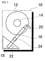
- Fig. 1 shows the configuration of the magnetic disk device of a first embodiment of the invention
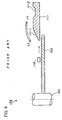
- Fig. 2 is a cross-sectional view of the ramp mechanism of Fig. 1
- Fig. 3 is a top view of the ramp mechanism of Fig. 1
- Fig. 4 is a block diagram of the control unit in the magnetic disk device of Fig. 1.
- the disk device the example of a magnetic disk device is shown.
- the magnetic disk drive 10 has a magnetic disk 12; a spindle motor 14 which rotates the magnetic disk 12; an arm 16 having at the tip a head slider comprising a magnetic head 26; a VCM (Voice Coil Motor) 18 which moves the arm 16, comprising the head slider, in the radial direction of the magnetic disk 12; and a ramp 20, provided on the outer perimeter of the magnetic disk 12, to which the arm 16 is retracted.
- VCM Vehicle Coil Motor
- the VCM 18 comprises a fixed magnet and a driving coil provided at the posterior end of the arm 16.
- the arm 16 comprises a swing arm which rotates about a rotation axis 24.
- the VCM 18 is provided with an inner stopper 22, which limits the inner-perimeter position of the arm 16.
- the arm 16 and ramp 20 are explained using Fig. 2 and Fig. 3.
- the ramp 20 comprises an inclined surface 20-1, which rises at an incline from the side of the magnetic disk 12; a first level surface 20-2 which continues from the inclined surface; and a groove portion 20-3, continuing from the first level surface 20-2, provided between the first level surface 20-2 and a second level surface 20-4.
- a lift 28 (see Fig. 3) is provided at the tip of the arm 16, and a head slider 26 comprising a magnetic head is provided at the top of the arm 16.
- the magnetic head is also referenced by 26 below.
- a head unload (retraction) operation is an operation in which, by moving the arm 16 rightward in Fig. 2 and Fig. 3, the lift 28 of the arm 16 climbs over the inclined surface 20-1 of the ramp 20, past the first level surface 20-2 to reach the groove portion 20-3, and is stopped by the step portion with the second level surface 20-4. By this means the lift 28 falls precisely into the groove portion 20-3 and is parked.
- a head load operation is an operation in which the arm 16, parked in the groove portion 20-3, is moved leftward in Fig. 2 and Fig. 3, so that the lift 28 climbs over the inclined surface of the groove portion 20-3 and the first level surface 20-2, and slides down the inclined surface 20-1, so that the arm 16 comprising the head is returned to above the magnetic disk 12.
- This load and unload operation is performed by driving the VCM 18.
- the velocity is detected from the back-electromotive force of the VCM (actuator) 18 driving the arm 16 comprising the magnetic head, and the VCM 18 is velocity-controlled so that the magnetic head is loaded onto the magnetic disk 12 at a prescribed velocity, to prevent crashes.
- Fig. 4 is a block diagram of the control circuit 3 of the disk drive in Fig. 1, and in particular shows IC chip units.
- the HDC (hard disk controller) chip 5 controls the interface with the host CPU (not shown), including exchange of data and various commands with the host CPU, and generates control signals within the magnetic disk drive to control the recording and reproduction format on the magnetic disk 12.
- the MCU (microcontroller) chip 7 comprises a microprocessor (MPU) and similar.
- the MCU 7 executes servo control to position the magnetic head 26.
- the MCU 7 executes a program stored in memory, not shown, recognizes head position signals (servo information recognition and demodulation), and performs computation of control current values for the VCM 18 and SPM 14 of the SVC (Servo Combo Driver) 11, by means of servo control operations.
- the MCU 7 performs seek control processing and seek error retry processing, described below.
- the SVC chip 11 is a driving circuit for the spindle motor (SPM) 14 and VCM 18 of Fig. 1, and has a VCM driver 36 and spindle driver 37.
- the read channel chip 9 is a circuit to perform recording and reproduction.
- the read channel 9 has an AGC circuit 90 comprising a peak hold circuit and an integrated circuit as a circuit for demodulating servo patterns recorded on the magnetic disk 12, a modulation circuit to record write data from the host CPU onto the magnetic disk 12, and a demodulation circuit to reproduce data from the magnetic disk 12.
- the AGC (Automatic Gain Control) circuit 90 of the read channel chip 9 controls the reproduced voltage gain according to the reproduced voltage, so that the magnetic head reproduced voltage from the preamp 19 is held at a prescribed voltage.
- Fig. 5 is a diagram of the flow of seek processing in the first embodiment of the invention
- Fig. 6 is a diagram of the flow of seek error retry processing
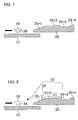
- Fig. 7 and Fig. 8 explain seek error retry operation.
- seek processing is explained using Fig. 5.
- a coarse control velocity curve is formed according to the distance between the current position of the magnetic head 26 and the seek target position.
- the MCU 7 demodulates the read output servo information to obtain the current position. As stated above, a track number indicated by a Gray code and an offset burst pattern A, B, C, D are recorded, as servo information, on each track.
- the MCU 7 judges whether demodulation has succeeded. For example, there are cases in which servo information cannot be detected from the read output, and the demodulated position cannot be obtained. Moreover, in coarse velocity control, when the error between the current position at the current sample as predicted from the previous sample and the current position detected from the current sample is large, demodulation is judged to have failed.
- the MCU 7 judges whether the demodulated current position is the target position. If the demodulated current position is not the target position, coarse control or fine control is executed, according to the position error. For example, if the position error between the target position and the current position is large, control is executed according to the velocity error between the target velocity and the current velocity based on the position error, according to the above-described coarse control velocity curve. This current velocity is obtained by dividing the difference between the current position at the time of the previous sample and the current position at the time of the current sample by the sample interval. If the position error is within a prescribed range (for example, 0.5 tracks), a transition is made to fine control (position control). Processing then returns to step S10. On the other hand, if the demodulated current position is the target position, seeking ends, and fine control (following control) is continued.
- a prescribed range for example, 0.5 tracks
- seek error retry processing is explained using Fig. 6, referring to Fig. 7 and Fig. 8.
- a check is performed to determine whether the magnetic head 26 has climbed onto the ramp 20, and the retry method is changed according to whether the head has or has not climbed onto the ramp 20.
- step S20 When, in step S16 of Fig. 5, a seek error is detected, seek error retry processing is begun.
- the MCU 7 judges whether the magnetic head 26 has climbed onto the ramp 20, as in Fig. 8. As the method of checking for climbing onto the ramp, MCU 7 monitors the raw waveform of the magnetic head 26 output from the head IC (preamp) 19, and if the waveform vanishes (the AC component is substantially "0"), MCU 7 judges that the head 26 has climbed onto the ramp 20. For example, if the waveform vanishes, when the AGC circuit 90 of the read channel 9 attempts to amplify the waveform, the gain continuously becomes at maximum gain. The firmware of the MCU 7 then monitors whether sticking (the continue of the maximum gain) of the gain of the AGC circuit 90 occurs. As shown in Fig. 7, when as a result of this check MCU 7 judges that the head 26 not have climbed onto the ramp 20, processing advances to step S26.
- the MCU 7 executes the above unload control. That is, the MCU 7 drives the VCM 18 to move the arm 16 rightward in Fig. 8.
- the lift 28 of the arm 16 climbs onto the inclined surface 20-1 of the ramp 20 and over the first level surface 20-2 to reach the groove portion 20-3, and stops at the step portion with the second level surface 20-4.
- the lift 28 falls precisely into the groove portion 20-3 and is parked.
- the MCU 7 performs the above-described load operation. That is, the MCU 7 drives the VCM 18 to move the arm 16, which is parked in the groove portion 20-3, leftward in Fig. 8.
- the lift 28 climbs over the inclined surface of the groove portion 20-3 and the first level surface 20-2, and slides down the inclined surface 20-1, so that the arm 16 comprising the head 26 is returned to above the magnetic disk 12.
- the velocity is detected from the back-electromotive force of the VCM (actuator) 18 driving the arm 16 comprising the magnetic head, and the VCM 18 is velocity-controlled to load the magnetic head onto the magnetic disk 12 at a prescribed velocity, to prevent crashing.
- the MCU 7 drives the VCM 18 to move the magnetic head 26 in seek movement inward over the magnetic disk 12, and tracks to the prescribed track.
- the MCU 7 takes the tracking position as the current position, and causes the magnetic head 26 to seek to the target track through the seek processing of the above-described Fig. 5.
- the MCU 7 judges whether seeking has ended normally. The MCU 7 judges, for example, whether the above-described seek error has occurred. If seeking has ended normally, seek error retry ends. On the other hand, if seeking does not end normally, a judgment is made as to whether the number of retries is within a stipulated number. If the number of retries is within the stipulated number, processing ends with an error, and processing returns to step S22. If the number of retries exceeds the stipulated number, processing ends anomalously.
- this embodiment can be realized without adding special functions. Further, the gain of the AGC circuit is monitored for sticking to judge whether the head has climbed onto the ramp 20, so that judgment can be performed simply by the firmware without providing a special mechanism.
- the AGC gain is used to judge whether the head has climbed onto the ramp; but judgment may also be made based on the raw waveform of the magnetic head, or another mechanism to detect climbing onto the ramp may be provided.
Landscapes
- Moving Of Head For Track Selection And Changing (AREA)
- Supporting Of Heads In Record-Carrier Devices (AREA)
Applications Claiming Priority (1)
| Application Number | Priority Date | Filing Date | Title |
|---|---|---|---|
| JP2005023548A JP4260754B2 (ja) | 2005-01-31 | 2005-01-31 | デイスク装置のシークエラーリトライ方法及びデイスク装置 |
Publications (2)
| Publication Number | Publication Date |
|---|---|
| EP1686568A2 true EP1686568A2 (de) | 2006-08-02 |
| EP1686568A3 EP1686568A3 (de) | 2007-10-03 |
Family
ID=34941727
Family Applications (1)
| Application Number | Title | Priority Date | Filing Date |
|---|---|---|---|
| EP05253803A Withdrawn EP1686568A3 (de) | 2005-01-31 | 2005-06-20 | Verfahren zur Wiederholung eines Spursuchverfahrens bei Suchfehler und Plattengerät |
Country Status (5)
| Country | Link |
|---|---|
| US (1) | US7113363B2 (de) |
| EP (1) | EP1686568A3 (de) |
| JP (1) | JP4260754B2 (de) |
| KR (1) | KR100708268B1 (de) |
| CN (1) | CN1815616A (de) |
Families Citing this family (6)
| Publication number | Priority date | Publication date | Assignee | Title |
|---|---|---|---|---|
| KR100734291B1 (ko) * | 2005-12-07 | 2007-07-02 | 삼성전자주식회사 | 하드디스크 드라이브의 리트랙트 제어 방법 그리고 이를적용한 하드디스크 드라이브 |
| KR100761856B1 (ko) * | 2006-08-22 | 2007-09-28 | 삼성전자주식회사 | 시크 리트라이 조건에서의 서보 제어 방법 및 장치와 이를이용한 디스크 드라이브 |
| JP2008186533A (ja) * | 2007-01-30 | 2008-08-14 | Fujitsu Ltd | 緊急退避検証装置および媒体記憶装置 |
| JP2010277660A (ja) * | 2009-05-29 | 2010-12-09 | Hitachi Global Storage Technologies Netherlands Bv | ディスク・ドライブ及びそのエラー回復処理の方法 |
| US9111560B1 (en) * | 2015-01-26 | 2015-08-18 | Seagate Technology Llc | Dynamic configuration of seek recovery in a disk drive |
| CN108598141B (zh) | 2018-06-27 | 2020-12-11 | 昆山国显光电有限公司 | 一种像素显示模组以及制作像素显示模组的掩膜板 |
Citations (1)
| Publication number | Priority date | Publication date | Assignee | Title |
|---|---|---|---|---|
| US20010005294A1 (en) | 1999-12-22 | 2001-06-28 | Rohm Co., Ltd | Disk device |
Family Cites Families (8)
| Publication number | Priority date | Publication date | Assignee | Title |
|---|---|---|---|---|
| JPH02128362A (ja) * | 1988-11-08 | 1990-05-16 | Nec Corp | 磁気ディスク装置 |
| JPH08293176A (ja) * | 1995-04-21 | 1996-11-05 | Fujitsu Ltd | ディスク装置 |
| JP2752937B2 (ja) * | 1995-11-14 | 1998-05-18 | 茨城日本電気株式会社 | 磁気ディスク装置 |
| KR100205287B1 (ko) | 1996-05-08 | 1999-07-01 | 윤종용 | 하드 디스크 드라이브의 액츄에이터 언래칭 감지장치 및 방법 |
| JP3016476B2 (ja) * | 1997-06-27 | 2000-03-06 | インターナショナル・ビジネス・マシーンズ・コーポレイション | ヘッド機構制御装置およびディスクドライブ装置ならびにヘッドアンロード制御方法 |
| JP2001093104A (ja) | 1999-09-22 | 2001-04-06 | Toshiba Corp | 磁気ディスク装置の動作エラー回復方法および磁気ディスク装置 |
| JP2003077240A (ja) * | 2001-08-30 | 2003-03-14 | Toshiba Corp | ディスク装置及び同装置におけるヘッドロード制御方法 |
| KR100640624B1 (ko) * | 2005-01-04 | 2006-10-31 | 삼성전자주식회사 | 디스크 드라이브에서의 언로딩 위치 제어 방법 |
-
2005
- 2005-01-31 JP JP2005023548A patent/JP4260754B2/ja not_active Expired - Fee Related
- 2005-06-20 EP EP05253803A patent/EP1686568A3/de not_active Withdrawn
- 2005-07-11 KR KR1020050062278A patent/KR100708268B1/ko not_active Expired - Fee Related
- 2005-07-15 US US11/182,104 patent/US7113363B2/en not_active Expired - Lifetime
- 2005-07-18 CN CNA2005100860899A patent/CN1815616A/zh active Pending
Patent Citations (1)
| Publication number | Priority date | Publication date | Assignee | Title |
|---|---|---|---|---|
| US20010005294A1 (en) | 1999-12-22 | 2001-06-28 | Rohm Co., Ltd | Disk device |
Also Published As
| Publication number | Publication date |
|---|---|
| CN1815616A (zh) | 2006-08-09 |
| US7113363B2 (en) | 2006-09-26 |
| US20060171061A1 (en) | 2006-08-03 |
| JP4260754B2 (ja) | 2009-04-30 |
| JP2006209902A (ja) | 2006-08-10 |
| EP1686568A3 (de) | 2007-10-03 |
| KR20060087991A (ko) | 2006-08-03 |
| KR100708268B1 (ko) | 2007-04-17 |
Similar Documents
| Publication | Publication Date | Title |
|---|---|---|
| US7072135B2 (en) | Disk apparatus, head retracting method and head actuator control circuit | |
| US6735033B1 (en) | Method for recovering from shock events occurring to a disk drive during data write operations to improve data reliability | |
| US7046475B2 (en) | Apparatus and method for controlling head unload operation in disk drive | |
| US7545593B1 (en) | Magnetic storage systems and methods with tighter write fault window to improve reliability | |
| KR100255207B1 (ko) | 하드 디스크 드라이브의 안정된 언래치 제어 방법 | |
| KR100412344B1 (ko) | 헤드비행고도에 따른 데이타 라이트 제어방법 | |
| US7663833B2 (en) | Controller, storage apparatus and control method | |
| EP1396846B1 (de) | Steuerungsverfahren und -vorrichtung für Festplattenlaufwerk | |
| US7113363B2 (en) | Seek error retry method of a disk device and disk device | |
| US7551389B2 (en) | Disk drive and method of retracting head thereof | |
| US7349174B2 (en) | Soft sensor for operating shock in a disc drive | |
| US6995943B1 (en) | Off-track error recovery method and apparatus for disk drive | |
| US7916593B2 (en) | Optical disk device and method of control of an optical disk utilizing retry feature | |
| US7483233B2 (en) | Method and apparatus for driving VCM unloading HDD head | |
| US7995302B2 (en) | Disk drive device and control method of unloading corresponding to fall detection in disk drive device | |
| JP4286110B2 (ja) | デイスク装置、ヘッド退避方法及びヘッドアクチュエータ制御回路 | |
| US8125729B2 (en) | Disk drive and error-recovery processing method | |
| US7099106B2 (en) | Deceleration of head in disc drive according to a desired deceleration profile | |
| US7570449B2 (en) | Retract control method of HDD and HDD using the same | |
| KR100640656B1 (ko) | 헤드 제어 방법 및 그 장치 | |
| US20110249358A1 (en) | Apparatus and method of detecting a defective sector in a disk drive | |
| JP2006164335A (ja) | 光ディスク装置および情報記録方法 | |
| JPH1092129A (ja) | ディスク装置及び同装置に適用されるヘッド移動制御方法 | |
| JP2001184816A (ja) | ディスク記憶装置 |
Legal Events
| Date | Code | Title | Description |
|---|---|---|---|
| PUAI | Public reference made under article 153(3) epc to a published international application that has entered the european phase |
Free format text: ORIGINAL CODE: 0009012 |
|
| AK | Designated contracting states |
Kind code of ref document: A2 Designated state(s): AT BE BG CH CY CZ DE DK EE ES FI FR GB GR HU IE IS IT LI LT LU MC NL PL PT RO SE SI SK TR |
|
| AX | Request for extension of the european patent |
Extension state: AL BA HR LV MK YU |
|
| PUAL | Search report despatched |
Free format text: ORIGINAL CODE: 0009013 |
|
| AK | Designated contracting states |
Kind code of ref document: A3 Designated state(s): AT BE BG CH CY CZ DE DK EE ES FI FR GB GR HU IE IS IT LI LT LU MC NL PL PT RO SE SI SK TR |
|
| AX | Request for extension of the european patent |
Extension state: AL BA HR LV MK YU |
|
| 17P | Request for examination filed |
Effective date: 20080325 |
|
| AKX | Designation fees paid |
Designated state(s): DE FR GB |
|
| 17Q | First examination report despatched |
Effective date: 20080521 |
|
| RAP1 | Party data changed (applicant data changed or rights of an application transferred) |
Owner name: TOSHIBA STORAGE DEVICE CORPORATION |
|
| STAA | Information on the status of an ep patent application or granted ep patent |
Free format text: STATUS: THE APPLICATION IS DEEMED TO BE WITHDRAWN |
|
| 18D | Application deemed to be withdrawn |
Effective date: 20100701 |