EP1685014B2 - Angetriebenes fahrwerk für schienenfahrzeuge, insbesondere drehgestelle für niederflurfahrzeuge - Google Patents
Angetriebenes fahrwerk für schienenfahrzeuge, insbesondere drehgestelle für niederflurfahrzeuge Download PDFInfo
- Publication number
- EP1685014B2 EP1685014B2 EP04797860.6A EP04797860A EP1685014B2 EP 1685014 B2 EP1685014 B2 EP 1685014B2 EP 04797860 A EP04797860 A EP 04797860A EP 1685014 B2 EP1685014 B2 EP 1685014B2
- Authority
- EP
- European Patent Office
- Prior art keywords
- wheel
- vehicles
- coupling
- low
- chassis
- Prior art date
- Legal status (The legal status is an assumption and is not a legal conclusion. Google has not performed a legal analysis and makes no representation as to the accuracy of the status listed.)
- Expired - Lifetime
Links
- 230000008878 coupling Effects 0.000 claims abstract description 26
- 238000010168 coupling process Methods 0.000 claims abstract description 26
- 238000005859 coupling reaction Methods 0.000 claims abstract description 26
- 230000000712 assembly Effects 0.000 claims 1
- 238000000429 assembly Methods 0.000 claims 1
- 230000005540 biological transmission Effects 0.000 description 2
- 230000009977 dual effect Effects 0.000 description 2
- 238000005461 lubrication Methods 0.000 description 2
- 230000006835 compression Effects 0.000 description 1
- 238000007906 compression Methods 0.000 description 1
- 238000007598 dipping method Methods 0.000 description 1
- 239000000314 lubricant Substances 0.000 description 1
- 239000000725 suspension Substances 0.000 description 1
Images
Classifications
-
- B—PERFORMING OPERATIONS; TRANSPORTING
- B61—RAILWAYS
- B61C—LOCOMOTIVES; MOTOR RAILCARS
- B61C9/00—Locomotives or motor railcars characterised by the type of transmission system used; Transmission systems specially adapted for locomotives or motor railcars
- B61C9/38—Transmission systems in or for locomotives or motor railcars with electric motor propulsion
- B61C9/52—Transmission systems in or for locomotives or motor railcars with electric motor propulsion with transmission shafts at an angle to the driving axles
-
- B—PERFORMING OPERATIONS; TRANSPORTING
- B61—RAILWAYS
- B61C—LOCOMOTIVES; MOTOR RAILCARS
- B61C9/00—Locomotives or motor railcars characterised by the type of transmission system used; Transmission systems specially adapted for locomotives or motor railcars
- B61C9/38—Transmission systems in or for locomotives or motor railcars with electric motor propulsion
- B61C9/44—Transmission systems in or for locomotives or motor railcars with electric motor propulsion with hollow transmission shaft concentric with wheel axis
-
- B—PERFORMING OPERATIONS; TRANSPORTING
- B61—RAILWAYS
- B61F—RAIL VEHICLE SUSPENSIONS, e.g. UNDERFRAMES, BOGIES OR ARRANGEMENTS OF WHEEL AXLES; RAIL VEHICLES FOR USE ON TRACKS OF DIFFERENT WIDTH; PREVENTING DERAILING OF RAIL VEHICLES; WHEEL GUARDS, OBSTRUCTION REMOVERS OR THE LIKE FOR RAIL VEHICLES
- B61F3/00—Types of bogies
- B61F3/16—Types of bogies with a separate axle for each wheel
Definitions
- the invention relates to a powered chassis for rail vehicles, especially bogies for low-floor vehicles.
- the wheels in the chassis longitudinal direction or parallel to the vehicle longitudinal axis considered individually mounted on the chassis or bogie, d. H. There is no axle shaft connection between the wheels, whereby the thus freed space is used for lowering the carriage floor.
- a drive unit designed as a longitudinal drive This includes a longitudinally mounted central motor with drive shafts. These are each connected via an angular gear, in particular in the form of a bevel gear with the driven wheel. The coupling between the output of the angle gear and the wheel via a gimbal double clutch.
- the angular gear as a bevel gear while coupled to the réellekegelrad hollow shaft is connected to the first coupling plane of the gimbal dual clutch and via this with a guided through the hollow shaft Kardanhohlwelle.
- This cardan hollow shaft is coupled via the second coupling plane with the wheel.
- the drive units are mounted on the bogie. Both the prime mover and the angle gear are suspended on the bogie. Due to this connection and support of the drive units on the bogie causes a deflection on the bogie also a corresponding deflection of the drive unit, in particular the angle gear. In order to ensure the required ground clearance in all functional or load conditions, the theoretically possible maximum compression travel must therefore be taken into account when designing the gearbox.
- the angular gear in particular the at least indirectly coupled to the wheels drive gear can not be arbitrarily increased in diameter and thus the transmittable torque, so that for a given space, the transmittable torque is limited.
- Another resulting disadvantage is that the reliability of the angular gear and thus the entire system is no longer given due to the associated tightness and lubrication problem.
- complex additional measures to ensure the supply of the teeth with sufficient lubricant are required.
- these are usually determined by additional design measures and / or the provision of additional conveyors.
- a generically driven chassis for bogies of low-floor vehicles with at least two successively arranged on each chassis longitudinal side and driven by a drive unit wheels is from the document DE 199 45 464 A1 previously known.
- the wheels are individually mounted on the bogie via bearings, each drive unit comprising at least one prime mover, which is at least indirectly connected via a respective angular gear and a flexible coupling in the form of, for example, a connecting rod coupling with the wheels.
- the elastic coupling is designed as a single-notch coupling, and the connection between the bevel gear and the wheel is free of a further coupling plane.
- the embodiment described here has the disadvantage that the coupling of the individual coupling elements takes place directly with the wheel drive shaft, so that it has to be designed correspondingly rigid, wherein the elements must be dimensioned accordingly, as they are exposed to high loads and also the connection thus not directly
- the individual coupling elements can be done, but appropriate fasteners are required, which in turn claim space in the axial and radial directions.
- the invention therefore an object of the invention to develop a driven chassis of the type mentioned in such a way that the disadvantages mentioned are avoided with unchanged available space.
- a suitability for transmitting higher torques should be sought when using the same space or smaller size.
- the design effort is kept as low as possible and reduce the required number of components.
- the output gear optimum lubrication conditions are created over the entire operating range and in a variety of driving conditions.
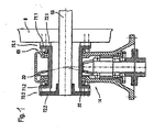
- FIG. 1 illustrates an approach according to the invention for reducing the disadvantages mentioned above using a non-cardanically acting double clutch 69 based on a detail of a drive unit 9, which serves one of an axis, preferably rigid axle 68 arranged wheel 4.
- the drive is via a drive machine, which is preferably installed longitudinally and is connected to the wheel 6 via an angle gear 14. This is executed in the simplest case as a bevel gear.
- the output is formed by Fantasyrad 20. This is connected to the wheel 6 via a first coupling plane 70.1.
- the individual clutches of the dual clutch 69 have for this purpose a first coupling element 71.1 and 71.2, which is rotatably connected to the hollow shaft 22 or forms a structural unit with this, and at least indirectly with this operatively engageable second coupling element 72.1, which is rotatably connected to the wheel 6 and a second coupling element 72.2, which is rotatably connected to the axis 68.
- the second coupling element 72.1 or 72.2 is formed in each case as axle star with four or more star-shaped arms.
- the hollow shaft is for this purpose connected to a first coupling element 71.1, 71.2, for example in the form of a hollow shaft star .
- the individual coupling elements can be carried in electro-mechanical drive units of the grounding brushes.
Landscapes
- Engineering & Computer Science (AREA)
- Mechanical Engineering (AREA)
- Chemical & Material Sciences (AREA)
- Combustion & Propulsion (AREA)
- Transportation (AREA)
- Gear Transmission (AREA)
- Arrangement Or Mounting Of Propulsion Units For Vehicles (AREA)
- Arrangement Of Transmissions (AREA)
- Platform Screen Doors And Railroad Systems (AREA)
- Handcart (AREA)
- Fittings On The Vehicle Exterior For Carrying Loads, And Devices For Holding Or Mounting Articles (AREA)
- Other Liquid Machine Or Engine Such As Wave Power Use (AREA)
Description
- Die Erfindung betrifft ein angetriebenes Fahrwerk für Schienenfahrzeuge, insbesondere Drehgestelle für Niederflurfahrzeuge.
- Angetriebene Fahrwerke für Schienenfahrzeuge, insbesondere Drehgestelle für Niederflurfahrzeuge sind in unterschiedlichsten Ausführungen aus dem Stand der Technik bekannt. Stellvertretend wird auf nachfolgend genannte Druckschriften verwiesen:
- 1) Voith: "Mechanische Antriebskomponenten für Schienenfahrzeuge - Referenzen", G 1567 d 3/2002, S. 3, 4
- 2)
EP 0698540 B1 - Bei diesen Ausführungen sind die Räder in Fahrwerkslängsrichtung bzw. parallel zur Fahrzeuglängsachse betrachtet jeweils einzeln am Fahrwerk oder Drehgestell gelagert, d. h. es besteht zwischen den Rädern keine Achswellenverbindung, wodurch der dadurch frei gewordene Raum zur Absenkung des Wagenbodens genutzt wird. Wenigstens zwei in Fahrwerkslängsrichtung betrachtet hintereinander angeordnete Räder einer Fahrzeugseite sind jeweils über eine als Längsantrieb ausgeführte Antriebseinheit antreibbar. Diese umfasst einen längs eingebauten Zentralmotor mit Antriebswellen. Diese sind jeweils über ein Winkelgetriebe, insbesondere in Form eines Kegelradgetriebes mit dem anzutreibenden Rad verbunden. Dabei erfolgt die Kopplung zwischen dem Ausgang der Winkelgetriebe und dem Rad über eine kardanische Doppelkupplung. Bei Ausführung des Winkelgetriebes als Kegelradgetriebe ist dabei die mit dem Ausgangskegelrad gekoppelte Hohlwelle mit der ersten Kupplungsebene der kardanischen Doppelkupplung und über diese mit einer durch die Hohlwelle geführten Kardanhohlwelle verbunden. Diese Kardanhohlwelle ist über die zweite Kupplungsebene mit dem Rad gekoppelt. Die Antriebseinheiten sind am Drehgestell gelagert. Dabei werden sowohl die Antriebsmaschine als auch das Winkelgetriebe am Drehgestell aufgehangen. Aufgrund dieser Anbindung und Abstützung der Antriebseinheiten am Drehgestell bewirkt eine Einfederung am Drehgestell auch eine entsprechende Einfederung der Antriebseinheit, insbesondere des Winkelgetriebes. Um die erforderliche Bodenfreiheit in allen Funktions- bzw. Belastungszuständen zu gewährleisten, muss bei der Auslegung des Getriebes daher der theoretisch mögliche maximale Einfederweg berücksichtigt werden. Dies bedeutet jedoch, dass das Winkelgetriebe, insbesondere das mit den Rädern wenigstens mittelbar gekoppelte Antriebszahnrad nicht beliebig hinsichtlich des Durchmessers und damit des übertragbaren Momentes vergrößert werden kann, so dass bei vorgegebenem Bauraum das übertragbare Moment begrenzt ist. Ein weiterer sich daraus ergebender Nachteil besteht darin, dass auch die Zuverlässigkeit des Winkelgetriebes und damit des gesamten Systems aufgrund der damit verbundenen Dichtheits- und Schmierungsproblematik nicht mehr gegeben ist. Insbesondere ist je nach Neigung des Getriebes beim Fahren an Steigungen oder im Gefälle ein Eintauchen des Ausgangszahnrades in den im Gehäuse vorhandenen Getriebeölsumpf nicht mehr gegeben. Um die üblicherweise daraus.resultierenden Verzahnungsschäden in diesen Fahrzuständen zu verhindern, sind aufwendige zusätzliche Maßnahmen zur Gewährleistung der Versorgung der Verzahnung mit ausreichend Schmiermittel erforderlich. Diese werden jedoch in der Regel durch zusätzliche konstruktive Maßnahmen und/oder das Vorsehen zusätzlicher Fördereinrichtungen bestimmt.
- Ein gattungsgemäß angetriebenes Fahrwerk für Drehgestelle von Niederflurfahrzeugen mit wenigstens zwei hintereinander auf jeder Fahrwerkslängsseite angeordneten und über eine Antriebseinheit antreibbaren Rädern ist aus der Druckschrift
DE 199 45 464 A1 vorbekannt. Die Räder sind einzeln am Drehgestell über Lagerungen gelagert, wobei jede Antriebseinheit wenigstens eine Antriebsmaschine umfasst, die wenigstens mittelbar über jeweils ein Winkelgetriebe und eine elastische Kupplung in Form beispielsweise einer Pleuelstangenkupplung mit den Rädern verbunden ist. Die elastische Kupplung ist dabei als Einebenekupplung ausgeführt, und die Verbindung zwischen Winkelgetriebe und Rad ist frei von einer weiteren Kupplungsebene. Die hier beschriebene Ausführung hat den Nachteil, dass die Kopplung der einzelnen Kupplungselemente direkt mit der Radantriebswelle erfolgt, so dass diese entsprechend starr auszulegen ist, wobei die Elemente entsprechend dimensioniert werden müssen, da diese hohen Belastungen ausgesetzt sind und ferner die Anbindung somit nicht direkt an den einzelnen Kupplungselementen erfolgen kann, sondern entsprechende Verbindungselemente erforderlich sind, die wiederum Bauraum in axialer und in radialer Richtung beanspruchen. - Bezüglich weiterer Ausführungen derartiger Fahrwerksantriebe wird auf
DE 94 06 843 U1 sowieEP 0567 445 A verwiesen. Aus der erstgenannten Druckschrift ist dabei eine Ausführung vorbekannt, bei welcher die Kopplung zwischen einem Kegelradtrieb und dem Rad über ein elastisches Kupplungselement erfolgt, wobei der Ausgang des Kegelradtriebes und der Radachse in unterschiedlichen Ebenen liegen und damit diese Lösung parallel zur Fahrzeuglängsachse Bauraum benötigt. - Der Erfindung lag daher die Aufgabe zugrunde, ein angetriebenes Fahrwerk der eingangs genannten Art derart weiterzuentwickeln, dass die genannten Nachteile bei unverändert zur Verfügung stehendem Bauraum vermieden werden. Dabei ist eine Eignung zur Übertragung höherer Drehmomente bei Nutzung des gleichbleibenden Bauraumes oder geringerer Größe anzustreben. Der konstruktive Aufwand ist möglichst gering zu halten und die erforderliche Bauteilanzahl zu reduzieren. Für das Winkelgetriebe, insbesondere das Ausgangszahnrad sind über den gesamten Betriebsbereich und in unterschiedlichsten Fahrzuständen optimale Schmierbedingungen zu schaffen.
- Die erfindungsgemäße Lösung ist durch die Merkmale des Anspruch 16 charakterisiert.
- Die erfindungsgemäßen Lösungen werden nachfolgend anhand der Figur erläutert.
- Die
Figur 1 verdeutlicht einen erfindungsgemäßen Ansatz zur Verringerung der eingangs genannten Nachteile unter Verwendung einer nicht kardanisch wirkenden Doppelkupplung 69 anhand eins Ausschnittes aus einer Antriebseinheit 9, die dem eines auf einer Achse, vorzugsweise starren Achse 68 angeordneten Rades 4 dient. Der Antrieb erfolgt über eine Antriebsmaschine, welche vorzugsweise längs eingebaut ist und mit dem Rad 6 über ein Winkelgetriebe 14 verbunden ist. Dieses ist im einfachsten Fall als Kegelradgetriebe ausgeführt. Der Abtrieb wird vom Ausgangskegelrad 20 gebildet. Dieses ist mit dem Rad 6 über eine erste Kupplungsebene 70.1 verbunden. Die Verbindung der Achse 68 mit dem Ausgang des Winkelgetriebes 14 und dem Rad 6 erfolgt über die das Kegelrad 20 tragende Hohlwelle 22. Die einzelnen Kupplungen der Doppelkupplung 69 weisen dazu ein erstes Kupplungselement 71.1 bzw. 71.2 auf, das mit der Hohlwelle 22 drehfest verbunden ist oder mit diesem eine bauliche Einheit bildet, und ein wenigstens mittelbar mit diesem in Wirkverbindung bringbares zweites Kupplungselement 72.1, das drehfest mit dem Rad 6 verbunden ist und ein zweites Kupplungselement 72.2, das drehfest mit der Achse 68 verbunden ist. Dazu ist beispielsweise das zweite Kupplungselement 72.1 oder 72.2 jeweils als Achsstern mit vier oder mehrsternförmigen Armen ausgebildet. Über elastische Lagerpakete, insbesondere Gummilagerpakete wird dann die Verbindung zur Hohlwelle, welche als eine, die Achse 68 hohlwellenartig umschließende Welle ausgeführt ist, hergestellt. Die Hohlwelle ist dazu mit einem ersten Kupplungselement 71.1, 71.2 beispielsweise in Form eines Hohlwellensterns verbunden.. Die einzelnen Kupplungselemente können dabei in elektro-mechanischen Antriebseinheiten von den Erdungsbürsten getragen werden.
Claims (1)
- Angetriebenes Fahrwerk (2) für Schienenfahrzeuge (3), insbesondere für Drehgestelle von Niederflurfahrzeugen1.1 mit wenigstens einem auf einer Achse (68) angeordneten und über eine Antriebseinheit (9) antreibbaren Rad (6);1.2 jede Antriebseinheit (9) umfasst wenigstens eine Antriebsmaschine (11), die wenigstens mittelbar über jeweils ein Winkelgetriebe (14) und eine elastische Kupplung mit den Rädern (4, 6) verbunden ist; gekennzeichnet durch die folgenden Merkmale:1.3 der Ausgang des Winkelgetriebes (14) wird von einer Hohlwelle (22) gebildet, welche über eine nicht kardanisch wirkende Doppelkupplung (69) mit dem Rad (6) direkt und der Achse (68) verbunden ist, wobei1.4 die Hohlwelle (22) über elastische Lagerpakete mit dem Rad (6) und der Achse (68) verbunden ist.
Applications Claiming Priority (2)
| Application Number | Priority Date | Filing Date | Title |
|---|---|---|---|
| DE10354141A DE10354141A1 (de) | 2003-11-19 | 2003-11-19 | Angetriebenes Fahrwerk für Schienenfahrzeuge, insbesondere Drehgestelle für Niederflurfahrzeuge |
| PCT/EP2004/012859 WO2005049401A2 (de) | 2003-11-19 | 2004-11-12 | Angetriebenes fahrwerk für schienenfahrzeuge, insbesondere drehstelle für niederflurfahrzeuge |
Publications (3)
| Publication Number | Publication Date |
|---|---|
| EP1685014A2 EP1685014A2 (de) | 2006-08-02 |
| EP1685014B1 EP1685014B1 (de) | 2008-06-18 |
| EP1685014B2 true EP1685014B2 (de) | 2014-10-29 |
Family
ID=34609136
Family Applications (1)
| Application Number | Title | Priority Date | Filing Date |
|---|---|---|---|
| EP04797860.6A Expired - Lifetime EP1685014B2 (de) | 2003-11-19 | 2004-11-12 | Angetriebenes fahrwerk für schienenfahrzeuge, insbesondere drehgestelle für niederflurfahrzeuge |
Country Status (8)
| Country | Link |
|---|---|
| EP (1) | EP1685014B2 (de) |
| CN (1) | CN100411928C (de) |
| AT (1) | ATE398563T1 (de) |
| AU (1) | AU2004291303A1 (de) |
| CA (1) | CA2546581A1 (de) |
| DE (2) | DE10354141A1 (de) |
| RU (1) | RU2322366C1 (de) |
| WO (1) | WO2005049401A2 (de) |
Families Citing this family (14)
| Publication number | Priority date | Publication date | Assignee | Title |
|---|---|---|---|---|
| ES2534870T3 (es) | 2012-05-30 | 2015-04-29 | Bombardier Transportation Gmbh | Disposición de impulsión para un órgano de rodadura |
| CN103273938A (zh) * | 2013-05-31 | 2013-09-04 | 南车株洲电力机车有限公司 | 一种转向架 |
| CN103381838A (zh) * | 2013-06-28 | 2013-11-06 | 长春轨道客车股份有限公司 | 100%低地板独立轮动力转向架单电机同轴两轮同步驱动机构 |
| CN103381839A (zh) * | 2013-06-28 | 2013-11-06 | 长春轨道客车股份有限公司 | 100%低地板轻轨车刚性轮对单电机同轴两轮驱动机构 |
| CN103381837A (zh) * | 2013-06-28 | 2013-11-06 | 长春轨道客车股份有限公司 | 100%低地板独立轮动力转向架双电机同轴两轮同步驱动机构 |
| RU2559397C2 (ru) * | 2013-12-11 | 2015-08-10 | Федеральное государственное бюджетное образовательное учреждение высшего профессионального образования "Омский государственный университет путей сообщения" (ОмГУПС (ОмИИТ)) | Устройство для уменьшения колебаний пассажирского вагона |
| DE102014214055A1 (de) | 2014-07-18 | 2016-01-21 | Siemens Aktiengesellschaft | Fahrwerk für ein Schienenfahrzeug |
| EP3199418A1 (de) * | 2016-01-26 | 2017-08-02 | Siemens Aktiengesellschaft | Doppelachsantrieb |
| ES2880439T3 (es) * | 2016-07-01 | 2021-11-24 | Zapadoceska Univerzita V Plzni | Unidad de accionamiento compacta para vehículos de tracción |
| CN107542909B (zh) * | 2017-10-19 | 2020-07-31 | 中车株洲电力机车有限公司 | 一种悬挂式单轨列车的齿轮箱 |
| CN107972684B (zh) * | 2017-12-29 | 2023-12-26 | 常州中车瑞泰装备科技有限公司 | 驱动轴系总成及轨道巡检车底盘 |
| CN109383531B (zh) * | 2018-10-09 | 2020-07-03 | 中车青岛四方机车车辆股份有限公司 | 轨道车辆防倾覆方法、驱动制动系统及轨道车辆 |
| DE102018009993A1 (de) * | 2018-12-19 | 2020-06-25 | Süddeutsche Gelenkscheibenfabrik GmbH & Co. KG | Antriebsanordnung für ein Schienenfahrzeug |
| CN113464625B (zh) * | 2021-07-02 | 2024-06-28 | 中车资阳机车有限公司 | 一种用于轨道车辆轮对驱动的空心轴结构 |
Citations (4)
| Publication number | Priority date | Publication date | Assignee | Title |
|---|---|---|---|---|
| DE471627C (de) † | 1929-02-14 | Sachsenwerk Licht & Kraft Ag | Einzelradantrieb fuer elektrisch betriebene Gleisfahrzeuge | |
| DE475175C (de) † | 1929-04-19 | Sachsenwerk Licht & Kraft Ag | Einzelradantrieb fuer elektrisch betriebene Gleisfahrzeuge | |
| DE1924814A1 (de) † | 1968-06-12 | 1970-01-02 | Maschf Augsburg Nuernberg Ag | Antrieb fuer zwei- oder mehrachsige Triebdrehgestelle von Schienenfahrzeugen |
| DE4429889A1 (de) † | 1994-08-24 | 1996-02-29 | Bergische Stahlindustrie | Angetriebenes Fahrwerk für Schienenfahrzeuge |
Family Cites Families (13)
| Publication number | Priority date | Publication date | Assignee | Title |
|---|---|---|---|---|
| US3453971A (en) * | 1965-05-20 | 1969-07-08 | Japan National Railway | Resilient railway wheel and axle drive |
| US4148262A (en) * | 1973-05-22 | 1979-04-10 | Carl Hurth Maschinen-Und Zahnradfabrik | Railway vehicle drive |
| DE2514265C3 (de) * | 1975-03-27 | 1979-06-13 | Siemens Ag, 1000 Berlin Und 8000 Muenchen | Antrieb für ein elektrisches Schienenfahrzeug |
| DE2853839A1 (de) * | 1978-12-13 | 1980-06-19 | Hurth Masch Zahnrad Carl | Doppelachsantrieb fuer drehgestelle von schienenfahrzeugen |
| EP0567445B1 (de) * | 1992-04-22 | 1996-01-10 | SGP Verkehrstechnik Gesellschaft m.b.H. | Fahrwerk für Schienenfahrzeuge, insbesondere Niederflurwagen |
| DE9406843U1 (de) * | 1994-04-23 | 1995-08-17 | Duewag Ag, 47829 Krefeld | Fahrwerk für Schienenfahrzeuge |
| AT406569B (de) * | 1995-03-23 | 2000-06-26 | Elin Ebg Traction Gmbh | Fahrwerk für ein schienenfahrzeug, insbesondere niederflurstrassenbahn |
| DE19538379C1 (de) * | 1995-10-14 | 1997-01-02 | Daimler Benz Ag | Zweirädiges Fahrwerk für spurgeführte Fahrzeuge |
| US6049138A (en) * | 1998-07-22 | 2000-04-11 | The Whitaker Corporation | Axle-mounted electrical power device having an improved drive coupling |
| CZ286660B6 (cs) * | 1998-09-22 | 2000-05-17 | Čkd Dopravní Systémy, A. S. | Dvouosý trakční podvozek nízkopodlažního kolejového vozidla s podélně uloženými nezávislými pohonnými jednotkami |
| DE19956976C2 (de) * | 1999-11-26 | 2001-09-06 | Gutehoffnungshuette Radsatz | Losradachse für Schienenfahrzeuge |
| DE19958367A1 (de) * | 1999-12-03 | 2001-06-13 | Voith Turbo Kg | Elastische Kupplung, insbesondere Lagerpaket-Gelenkkupplung |
| DE10032707A1 (de) * | 2000-07-07 | 2002-01-17 | Voith Turbo Kg | Antriebseinheit zum Antrieb mindestens einer Radantriebswelle, insbesondere einer Radsatzwelle |
-
2003
- 2003-11-19 DE DE10354141A patent/DE10354141A1/de not_active Withdrawn
-
2004
- 2004-11-12 WO PCT/EP2004/012859 patent/WO2005049401A2/de not_active Ceased
- 2004-11-12 CA CA002546581A patent/CA2546581A1/en not_active Abandoned
- 2004-11-12 AU AU2004291303A patent/AU2004291303A1/en not_active Abandoned
- 2004-11-12 DE DE502004007407T patent/DE502004007407D1/de not_active Expired - Lifetime
- 2004-11-12 CN CNB2004800339068A patent/CN100411928C/zh not_active Expired - Lifetime
- 2004-11-12 RU RU2006120568/11A patent/RU2322366C1/ru not_active IP Right Cessation
- 2004-11-12 EP EP04797860.6A patent/EP1685014B2/de not_active Expired - Lifetime
- 2004-11-12 AT AT04797860T patent/ATE398563T1/de active
Patent Citations (4)
| Publication number | Priority date | Publication date | Assignee | Title |
|---|---|---|---|---|
| DE471627C (de) † | 1929-02-14 | Sachsenwerk Licht & Kraft Ag | Einzelradantrieb fuer elektrisch betriebene Gleisfahrzeuge | |
| DE475175C (de) † | 1929-04-19 | Sachsenwerk Licht & Kraft Ag | Einzelradantrieb fuer elektrisch betriebene Gleisfahrzeuge | |
| DE1924814A1 (de) † | 1968-06-12 | 1970-01-02 | Maschf Augsburg Nuernberg Ag | Antrieb fuer zwei- oder mehrachsige Triebdrehgestelle von Schienenfahrzeugen |
| DE4429889A1 (de) † | 1994-08-24 | 1996-02-29 | Bergische Stahlindustrie | Angetriebenes Fahrwerk für Schienenfahrzeuge |
Also Published As
| Publication number | Publication date |
|---|---|
| EP1685014B1 (de) | 2008-06-18 |
| WO2005049401A2 (de) | 2005-06-02 |
| AU2004291303A1 (en) | 2005-06-02 |
| DE502004007407D1 (de) | 2008-07-31 |
| ATE398563T1 (de) | 2008-07-15 |
| DE10354141A1 (de) | 2005-06-23 |
| CA2546581A1 (en) | 2005-06-02 |
| EP1685014A2 (de) | 2006-08-02 |
| CN100411928C (zh) | 2008-08-20 |
| RU2322366C1 (ru) | 2008-04-20 |
| WO2005049401A3 (de) | 2006-02-16 |
| CN1882465A (zh) | 2006-12-20 |
| RU2006120568A (ru) | 2008-01-10 |
Similar Documents
| Publication | Publication Date | Title |
|---|---|---|
| EP1685014B2 (de) | Angetriebenes fahrwerk für schienenfahrzeuge, insbesondere drehgestelle für niederflurfahrzeuge | |
| DE10248173A1 (de) | Fahrzeug mit elektrischen Einzelradantrieben | |
| EP0010619B1 (de) | Elektromotor-Getriebe-Aggregat für den Antrieb von Schienenfahrzeugen wie Strassenbahnen o.dgl. | |
| EP1717090B1 (de) | Allradangetriebenes Kraftfahrzeug | |
| DE102013203567B4 (de) | Doppelrad-Antriebsmodul und Schwerlastfahrzeug | |
| EP1634756B1 (de) | Antriebseinrichtung | |
| EP0201493A1 (de) | Mehrachsfahrzeug mit einzelradantrieben. | |
| EP1247713A2 (de) | Triebfahrwerk für Schienenfahrzeuge ohne Radsätze | |
| EP1065122B1 (de) | Losradachse für Schienenfahrzeuge | |
| WO2020216512A1 (de) | Elektrischer achsantrieb für ein fahrzeug | |
| WO2020030434A1 (de) | Fahrzeugachse mit einer elektrischen antriebsvorrichtung und elektrische antriebsvorrichtung | |
| EP3480047A1 (de) | Zentral angetriebene anhängerachse | |
| EP0878368B1 (de) | Antriebseinheit für Schienenfahrzeuge | |
| DE102014218737A1 (de) | Zweistufiges Planetengetriebe zur Untersetzung hoher Drehzahlen | |
| DE68905410T2 (de) | Antriebsdrehgestell fuer schienenfahrzeuge. | |
| EP3628525A1 (de) | Kraftfahrzeug mit einem hilfsantrieb für eine lenkbare achse | |
| DE3938888B4 (de) | Verteilergetriebe | |
| DE3047413A1 (de) | Doppelachsantrieb fuer schienenfahrzeuge | |
| DE102024206097A1 (de) | Laufwerk mit einem Stützarm und Schienenfahrzeug mit einem solchen Laufwerk | |
| EP1733995A1 (de) | Verladefahrzeug | |
| DE102019129235A1 (de) | Antriebseinheit mit integriertem Achsgelenk | |
| DE102024206980A1 (de) | Antriebsaggregat für ein Kraftfahrzeug | |
| WO2024088896A1 (de) | Fahrwerk für ein schienenfahrzeug und schienenfahrzeug | |
| DE102024104270A1 (de) | Antriebseinheit und Doppelantriebseinheit, jeweils für ein Kraftfahrzeug, sowie Kraftfahrzeug | |
| DE102023114172A1 (de) | Antriebsanordnung für Fahrzeuge |
Legal Events
| Date | Code | Title | Description |
|---|---|---|---|
| PUAI | Public reference made under article 153(3) epc to a published international application that has entered the european phase |
Free format text: ORIGINAL CODE: 0009012 |
|
| 17P | Request for examination filed |
Effective date: 20060429 |
|
| AK | Designated contracting states |
Kind code of ref document: A2 Designated state(s): AT BE BG CH CY CZ DE DK EE ES FI FR GB GR HU IE IS IT LI LU MC NL PL PT RO SE SI SK TR |
|
| AX | Request for extension of the european patent |
Extension state: AL HR LT LV MK YU |
|
| DAX | Request for extension of the european patent (deleted) | ||
| GRAP | Despatch of communication of intention to grant a patent |
Free format text: ORIGINAL CODE: EPIDOSNIGR1 |
|
| GRAS | Grant fee paid |
Free format text: ORIGINAL CODE: EPIDOSNIGR3 |
|
| GRAA | (expected) grant |
Free format text: ORIGINAL CODE: 0009210 |
|
| AK | Designated contracting states |
Kind code of ref document: B1 Designated state(s): AT BE BG CH CY CZ DE DK EE ES FI FR GB GR HU IE IS IT LI LU MC NL PL PT RO SE SI SK TR |
|
| REG | Reference to a national code |
Ref country code: GB Ref legal event code: FG4D Free format text: NOT ENGLISH |
|
| REF | Corresponds to: |
Ref document number: 502004007407 Country of ref document: DE Date of ref document: 20080731 Kind code of ref document: P |
|
| REG | Reference to a national code |
Ref country code: CH Ref legal event code: EP |
|
| REG | Reference to a national code |
Ref country code: IE Ref legal event code: FG4D Free format text: LANGUAGE OF EP DOCUMENT: GERMAN |
|
| REG | Reference to a national code |
Ref country code: RO Ref legal event code: EPE |
|
| PG25 | Lapsed in a contracting state [announced via postgrant information from national office to epo] |
Ref country code: SI Free format text: LAPSE BECAUSE OF FAILURE TO SUBMIT A TRANSLATION OF THE DESCRIPTION OR TO PAY THE FEE WITHIN THE PRESCRIBED TIME-LIMIT Effective date: 20080618 |
|
| PG25 | Lapsed in a contracting state [announced via postgrant information from national office to epo] |
Ref country code: NL Free format text: LAPSE BECAUSE OF FAILURE TO SUBMIT A TRANSLATION OF THE DESCRIPTION OR TO PAY THE FEE WITHIN THE PRESCRIBED TIME-LIMIT Effective date: 20080618 Ref country code: PL Free format text: LAPSE BECAUSE OF FAILURE TO SUBMIT A TRANSLATION OF THE DESCRIPTION OR TO PAY THE FEE WITHIN THE PRESCRIBED TIME-LIMIT Effective date: 20080618 |
|
| NLV1 | Nl: lapsed or annulled due to failure to fulfill the requirements of art. 29p and 29m of the patents act | ||
| PG25 | Lapsed in a contracting state [announced via postgrant information from national office to epo] |
Ref country code: ES Free format text: LAPSE BECAUSE OF FAILURE TO SUBMIT A TRANSLATION OF THE DESCRIPTION OR TO PAY THE FEE WITHIN THE PRESCRIBED TIME-LIMIT Effective date: 20080929 Ref country code: SE Free format text: LAPSE BECAUSE OF FAILURE TO SUBMIT A TRANSLATION OF THE DESCRIPTION OR TO PAY THE FEE WITHIN THE PRESCRIBED TIME-LIMIT Effective date: 20080918 Ref country code: PT Free format text: LAPSE BECAUSE OF FAILURE TO SUBMIT A TRANSLATION OF THE DESCRIPTION OR TO PAY THE FEE WITHIN THE PRESCRIBED TIME-LIMIT Effective date: 20081118 Ref country code: IS Free format text: LAPSE BECAUSE OF FAILURE TO SUBMIT A TRANSLATION OF THE DESCRIPTION OR TO PAY THE FEE WITHIN THE PRESCRIBED TIME-LIMIT Effective date: 20081018 |
|
| REG | Reference to a national code |
Ref country code: IE Ref legal event code: FD4D |
|
| PG25 | Lapsed in a contracting state [announced via postgrant information from national office to epo] |
Ref country code: SK Free format text: LAPSE BECAUSE OF FAILURE TO SUBMIT A TRANSLATION OF THE DESCRIPTION OR TO PAY THE FEE WITHIN THE PRESCRIBED TIME-LIMIT Effective date: 20080618 |
|
| PLBI | Opposition filed |
Free format text: ORIGINAL CODE: 0009260 |
|
| 26 | Opposition filed |
Opponent name: SIEMENS AKTIENGESELLSCHAFT Effective date: 20090306 |
|
| PLAX | Notice of opposition and request to file observation + time limit sent |
Free format text: ORIGINAL CODE: EPIDOSNOBS2 |
|
| PG25 | Lapsed in a contracting state [announced via postgrant information from national office to epo] |
Ref country code: IE Free format text: LAPSE BECAUSE OF FAILURE TO SUBMIT A TRANSLATION OF THE DESCRIPTION OR TO PAY THE FEE WITHIN THE PRESCRIBED TIME-LIMIT Effective date: 20080618 Ref country code: DK Free format text: LAPSE BECAUSE OF FAILURE TO SUBMIT A TRANSLATION OF THE DESCRIPTION OR TO PAY THE FEE WITHIN THE PRESCRIBED TIME-LIMIT Effective date: 20080618 Ref country code: EE Free format text: LAPSE BECAUSE OF FAILURE TO SUBMIT A TRANSLATION OF THE DESCRIPTION OR TO PAY THE FEE WITHIN THE PRESCRIBED TIME-LIMIT Effective date: 20080618 Ref country code: BG Free format text: LAPSE BECAUSE OF FAILURE TO SUBMIT A TRANSLATION OF THE DESCRIPTION OR TO PAY THE FEE WITHIN THE PRESCRIBED TIME-LIMIT Effective date: 20080918 |
|
| PG25 | Lapsed in a contracting state [announced via postgrant information from national office to epo] |
Ref country code: MC Free format text: LAPSE BECAUSE OF NON-PAYMENT OF DUE FEES Effective date: 20081130 |
|
| REG | Reference to a national code |
Ref country code: CH Ref legal event code: PL |
|
| GBPC | Gb: european patent ceased through non-payment of renewal fee |
Effective date: 20081112 |
|
| PLAF | Information modified related to communication of a notice of opposition and request to file observations + time limit |
Free format text: ORIGINAL CODE: EPIDOSCOBS2 |
|
| PG25 | Lapsed in a contracting state [announced via postgrant information from national office to epo] |
Ref country code: IT Free format text: LAPSE BECAUSE OF FAILURE TO SUBMIT A TRANSLATION OF THE DESCRIPTION OR TO PAY THE FEE WITHIN THE PRESCRIBED TIME-LIMIT Effective date: 20080618 |
|
| REG | Reference to a national code |
Ref country code: FR Ref legal event code: ST Effective date: 20090731 |
|
| PG25 | Lapsed in a contracting state [announced via postgrant information from national office to epo] |
Ref country code: CH Free format text: LAPSE BECAUSE OF NON-PAYMENT OF DUE FEES Effective date: 20081130 Ref country code: LI Free format text: LAPSE BECAUSE OF NON-PAYMENT OF DUE FEES Effective date: 20081130 |
|
| PLBB | Reply of patent proprietor to notice(s) of opposition received |
Free format text: ORIGINAL CODE: EPIDOSNOBS3 |
|
| PG25 | Lapsed in a contracting state [announced via postgrant information from national office to epo] |
Ref country code: GB Free format text: LAPSE BECAUSE OF NON-PAYMENT OF DUE FEES Effective date: 20081112 |
|
| PG25 | Lapsed in a contracting state [announced via postgrant information from national office to epo] |
Ref country code: FI Free format text: LAPSE BECAUSE OF FAILURE TO SUBMIT A TRANSLATION OF THE DESCRIPTION OR TO PAY THE FEE WITHIN THE PRESCRIBED TIME-LIMIT Effective date: 20080618 |
|
| PG25 | Lapsed in a contracting state [announced via postgrant information from national office to epo] |
Ref country code: HU Free format text: LAPSE BECAUSE OF FAILURE TO SUBMIT A TRANSLATION OF THE DESCRIPTION OR TO PAY THE FEE WITHIN THE PRESCRIBED TIME-LIMIT Effective date: 20081219 Ref country code: CY Free format text: LAPSE BECAUSE OF FAILURE TO SUBMIT A TRANSLATION OF THE DESCRIPTION OR TO PAY THE FEE WITHIN THE PRESCRIBED TIME-LIMIT Effective date: 20080618 Ref country code: LU Free format text: LAPSE BECAUSE OF NON-PAYMENT OF DUE FEES Effective date: 20081112 |
|
| PG25 | Lapsed in a contracting state [announced via postgrant information from national office to epo] |
Ref country code: TR Free format text: LAPSE BECAUSE OF FAILURE TO SUBMIT A TRANSLATION OF THE DESCRIPTION OR TO PAY THE FEE WITHIN THE PRESCRIBED TIME-LIMIT Effective date: 20080618 |
|
| PG25 | Lapsed in a contracting state [announced via postgrant information from national office to epo] |
Ref country code: GR Free format text: LAPSE BECAUSE OF FAILURE TO SUBMIT A TRANSLATION OF THE DESCRIPTION OR TO PAY THE FEE WITHIN THE PRESCRIBED TIME-LIMIT Effective date: 20080919 |
|
| PG25 | Lapsed in a contracting state [announced via postgrant information from national office to epo] |
Ref country code: FR Free format text: LAPSE BECAUSE OF NON-PAYMENT OF DUE FEES Effective date: 20081130 |
|
| RIC2 | Information provided on ipc code assigned after grant |
Ipc: B61C 9/52 20060101AFI20120228BHEP Ipc: B61C 9/44 20060101ALI20120228BHEP Ipc: B61F 3/16 20060101ALI20120228BHEP |
|
| PGFP | Annual fee paid to national office [announced via postgrant information from national office to epo] |
Ref country code: RO Payment date: 20131111 Year of fee payment: 10 |
|
| PUAH | Patent maintained in amended form |
Free format text: ORIGINAL CODE: 0009272 |
|
| STAA | Information on the status of an ep patent application or granted ep patent |
Free format text: STATUS: PATENT MAINTAINED AS AMENDED |
|
| 27A | Patent maintained in amended form |
Effective date: 20141029 |
|
| AK | Designated contracting states |
Kind code of ref document: B2 Designated state(s): AT BE BG CH CY CZ DE DK EE ES FI FR GB GR HU IE IS IT LI LU MC NL PL PT RO SE SI SK TR |
|
| REG | Reference to a national code |
Ref country code: DE Ref legal event code: R102 Ref document number: 502004007407 Country of ref document: DE |
|
| REG | Reference to a national code |
Ref country code: DE Ref legal event code: R102 Ref document number: 502004007407 Country of ref document: DE Effective date: 20141029 |
|
| PG25 | Lapsed in a contracting state [announced via postgrant information from national office to epo] |
Ref country code: RO Free format text: LAPSE BECAUSE OF NON-PAYMENT OF DUE FEES Effective date: 20141112 |
|
| PGFP | Annual fee paid to national office [announced via postgrant information from national office to epo] |
Ref country code: BE Payment date: 20191120 Year of fee payment: 16 |
|
| PGFP | Annual fee paid to national office [announced via postgrant information from national office to epo] |
Ref country code: AT Payment date: 20191121 Year of fee payment: 16 |
|
| REG | Reference to a national code |
Ref country code: DE Ref legal event code: R082 Ref document number: 502004007407 Country of ref document: DE Ref country code: DE Ref legal event code: R081 Ref document number: 502004007407 Country of ref document: DE Owner name: VOITH PATENT GMBH, DE Free format text: FORMER OWNER: VOITH TURBO GMBH & CO. KG, 89522 HEIDENHEIM, DE |
|
| REG | Reference to a national code |
Ref country code: BE Ref legal event code: PD Owner name: VOITH PATENT GMBH; DE Free format text: DETAILS ASSIGNMENT: CHANGE OF OWNER(S), MERGE Effective date: 20201118 |
|
| REG | Reference to a national code |
Ref country code: AT Ref legal event code: MM01 Ref document number: 398563 Country of ref document: AT Kind code of ref document: T Effective date: 20201112 |
|
| REG | Reference to a national code |
Ref country code: BE Ref legal event code: MM Effective date: 20201130 |
|
| PG25 | Lapsed in a contracting state [announced via postgrant information from national office to epo] |
Ref country code: AT Free format text: LAPSE BECAUSE OF NON-PAYMENT OF DUE FEES Effective date: 20201112 |
|
| PG25 | Lapsed in a contracting state [announced via postgrant information from national office to epo] |
Ref country code: BE Free format text: LAPSE BECAUSE OF NON-PAYMENT OF DUE FEES Effective date: 20201130 |
|
| PGFP | Annual fee paid to national office [announced via postgrant information from national office to epo] |
Ref country code: DE Payment date: 20231121 Year of fee payment: 20 Ref country code: CZ Payment date: 20231103 Year of fee payment: 20 |
|
| REG | Reference to a national code |
Ref country code: DE Ref legal event code: R071 Ref document number: 502004007407 Country of ref document: DE |
|
| PG25 | Lapsed in a contracting state [announced via postgrant information from national office to epo] |
Ref country code: CZ Free format text: LAPSE BECAUSE OF EXPIRATION OF PROTECTION Effective date: 20241112 |
|
| PG25 | Lapsed in a contracting state [announced via postgrant information from national office to epo] |
Ref country code: CZ Free format text: LAPSE BECAUSE OF EXPIRATION OF PROTECTION Effective date: 20241112 |