EP3628525A1 - Kraftfahrzeug mit einem hilfsantrieb für eine lenkbare achse - Google Patents
Kraftfahrzeug mit einem hilfsantrieb für eine lenkbare achse Download PDFInfo
- Publication number
- EP3628525A1 EP3628525A1 EP19199616.4A EP19199616A EP3628525A1 EP 3628525 A1 EP3628525 A1 EP 3628525A1 EP 19199616 A EP19199616 A EP 19199616A EP 3628525 A1 EP3628525 A1 EP 3628525A1
- Authority
- EP
- European Patent Office
- Prior art keywords
- axle
- drive
- differential
- motor
- transmission
- Prior art date
- Legal status (The legal status is an assumption and is not a legal conclusion. Google has not performed a legal analysis and makes no representation as to the accuracy of the status listed.)
- Granted
Links
- 230000005540 biological transmission Effects 0.000 claims abstract description 28
- 230000002706 hydrostatic effect Effects 0.000 claims abstract description 18
- 239000000725 suspension Substances 0.000 claims abstract description 17
- 238000002485 combustion reaction Methods 0.000 claims abstract description 14
- 230000001419 dependent effect Effects 0.000 claims description 2
- 239000012530 fluid Substances 0.000 description 5
- 238000009434 installation Methods 0.000 description 5
- 238000010521 absorption reaction Methods 0.000 description 3
- 238000013016 damping Methods 0.000 description 2
- 230000009347 mechanical transmission Effects 0.000 description 2
- 238000012986 modification Methods 0.000 description 2
- 230000004048 modification Effects 0.000 description 2
- 238000010276 construction Methods 0.000 description 1
- 230000008878 coupling Effects 0.000 description 1
- 238000010168 coupling process Methods 0.000 description 1
- 238000005859 coupling reaction Methods 0.000 description 1
- 238000010586 diagram Methods 0.000 description 1
- 238000005516 engineering process Methods 0.000 description 1
- 230000001771 impaired effect Effects 0.000 description 1
Images

Classifications
-
- B—PERFORMING OPERATIONS; TRANSPORTING
- B60—VEHICLES IN GENERAL
- B60K—ARRANGEMENT OR MOUNTING OF PROPULSION UNITS OR OF TRANSMISSIONS IN VEHICLES; ARRANGEMENT OR MOUNTING OF PLURAL DIVERSE PRIME-MOVERS IN VEHICLES; AUXILIARY DRIVES FOR VEHICLES; INSTRUMENTATION OR DASHBOARDS FOR VEHICLES; ARRANGEMENTS IN CONNECTION WITH COOLING, AIR INTAKE, GAS EXHAUST OR FUEL SUPPLY OF PROPULSION UNITS IN VEHICLES
- B60K17/00—Arrangement or mounting of transmissions in vehicles
- B60K17/34—Arrangement or mounting of transmissions in vehicles for driving both front and rear wheels, e.g. four wheel drive vehicles
- B60K17/354—Arrangement or mounting of transmissions in vehicles for driving both front and rear wheels, e.g. four wheel drive vehicles having separate mechanical assemblies for transmitting drive to the front or to the rear wheels or set of wheels
-
- B—PERFORMING OPERATIONS; TRANSPORTING
- B60—VEHICLES IN GENERAL
- B60K—ARRANGEMENT OR MOUNTING OF PROPULSION UNITS OR OF TRANSMISSIONS IN VEHICLES; ARRANGEMENT OR MOUNTING OF PLURAL DIVERSE PRIME-MOVERS IN VEHICLES; AUXILIARY DRIVES FOR VEHICLES; INSTRUMENTATION OR DASHBOARDS FOR VEHICLES; ARRANGEMENTS IN CONNECTION WITH COOLING, AIR INTAKE, GAS EXHAUST OR FUEL SUPPLY OF PROPULSION UNITS IN VEHICLES
- B60K17/00—Arrangement or mounting of transmissions in vehicles
- B60K17/34—Arrangement or mounting of transmissions in vehicles for driving both front and rear wheels, e.g. four wheel drive vehicles
- B60K17/356—Arrangement or mounting of transmissions in vehicles for driving both front and rear wheels, e.g. four wheel drive vehicles having fluid or electric motor, for driving one or more wheels
-
- B—PERFORMING OPERATIONS; TRANSPORTING
- B60—VEHICLES IN GENERAL
- B60Y—INDEXING SCHEME RELATING TO ASPECTS CROSS-CUTTING VEHICLE TECHNOLOGY
- B60Y2200/00—Type of vehicle
- B60Y2200/10—Road Vehicles
- B60Y2200/14—Trucks; Load vehicles, Busses
- B60Y2200/141—Light trucks
-
- B—PERFORMING OPERATIONS; TRANSPORTING
- B60—VEHICLES IN GENERAL
- B60Y—INDEXING SCHEME RELATING TO ASPECTS CROSS-CUTTING VEHICLE TECHNOLOGY
- B60Y2200/00—Type of vehicle
- B60Y2200/10—Road Vehicles
- B60Y2200/14—Trucks; Load vehicles, Busses
- B60Y2200/142—Heavy duty trucks
Definitions
- the invention relates to a motor vehicle with an auxiliary drive for a steerable axle.
- EP 1 886 861 A2 a drive system comprising a conventional, mechanical rear axle driven via a drive shaft, the drive shaft being operatively connected to an axle differential of the rear axle.
- the drive system further comprises two front wheels 1 which can be driven by hydraulic wheel motors RM and which are arranged in a steerable manner on a front axle 3.
- the two RM wheel motors are integrated in a closed hydrostatic circuit.
- a main pump is mechanically driven via the mechanical drive train of the vehicle.
- the two wheel motors RM can be activated by a control valve. This enables considerable weight and efficiency advantages to be achieved compared to vehicles with permanent all-wheel drive, in particular in vehicles in which all-wheel drive is only required for a small part of the actual driving distance.
- Light vehicles are characterized by a rigid axle.
- Light vehicles in particular also commercial vehicles with a low payload, are characterized in particular by a single wheel suspension in the steering axle. Contrary to a continuous axle body of a rigid axle, which is connected to the frame / body of the vehicle via spring, damping and guide elements, much lighter and more delicate components are used for the independent wheel suspension.
- Such light vehicles with independent suspension usually have two, in some cases also three axles.
- the drive of these vehicles provides that at least one axle is driven by a mechanical drive train. This can be either the front axle or the rear axle.
- a mechanical drive train This can be either the front axle or the rear axle.
- Such vehicles with all-wheel drive are also known in practice.
- the drive power is transferred permanently or optionally to all axes. It is known from practice that the distribution of the drive force takes place mechanically via transfer cases and / or clutches and shafts. The disadvantage of this is that an assigned drive shaft along the vehicle axis is required for this. This also results in restrictions regarding the driving level.
- the hydrostatically driven wheel motors known from the prior art are generally disadvantageous for vehicles with independent wheel suspension. For reasons of driving dynamics, it is desirable to have the lowest possible unsprung mass of the wheel, which would be impaired by the comparatively heavy hydraulic wheel motors. Furthermore, the laying of hydraulic lines between the wheel part and the vehicle body is associated with disadvantages, since there is generally very little installation space available.
- the object of the invention is to provide an improved vehicle with which disadvantages of conventional technology can be avoided.
- the object of the invention is to provide a drive option in particular also for vehicles with a steerable axle and independent wheel suspension, which enables good driving behavior and takes up little installation space.
- the invention relates to a commercial vehicle with a drivable rigid first axle which can be driven and / or driven via a mechanical drive train which has an internal combustion engine.
- the motor vehicle also includes a steerable second axle with independent wheel suspension.
- the wheels of the second axle are therefore not arranged on a rigid axle, but can perform spring movements independently of one another.
- the first axle is preferably a rear axle and the second axle is a front axle of the vehicle.
- the commercial vehicle has only one rigid axle, ie the rigid first axle is the only rigid axle of the commercial vehicle. It is therefore a light commercial vehicle and not a heavy commercial vehicle which generally has two or more rigid axles.
- the second axle can be driven and / or driven by a hydrostatic auxiliary drive which has a drive motor in the form of a hydraulic motor, also referred to as a hydraulic motor, which distributes its drive power to the wheels of the second axis via a chassis-fixed transmission.
- the transmission can thus be a non-resilient transmission attached to the vehicle frame.
- the transmission can be designed as an axle differential, more preferably as a bevel gear differential.
- the drive motor is thus in particular not a wheel motor or wheel hub motor, but a drive motor which, for. B. can be arranged fixed to the chassis.
- the steerable second axle with independent suspension is therefore not driven the internal combustion engine, but by the auxiliary drive with the drive motor, which is operatively connected to the transmission.
- the drive power of the hydrostatic drive is provided by a power take-off (PTO) of the mechanical drive train, i.e. either via a power take-off provided on the internal combustion engine or via a mechanical transmission on the vehicle transmission, which translates the engine speed to the drive speed, provided power take-off.
- PTO power take-off
- the combination according to the invention of a mechanically driven rigid axle with a hydrostatically driven axle with independent wheel suspension offers the advantage, in particular for light commercial vehicles, that high torque can be transmitted to an additional axle, here the axle with independent wheel suspension, without an assigned drive shaft along it Longitudinal vehicle axis is required. Accordingly, there are also no restrictions with regard to the driving level due to such a drive shaft extending in the longitudinal direction of the vehicle. Furthermore, the mass of the wheel can be kept low, since no wheel hub motor is required, which means that the driving conditions are almost the same as those without the auxiliary drive.
- the drive motor can be arranged coaxially to an output of the axle differential, in particular to a driven shaft of the axle differential. This means that an axis of rotation of a drive shaft of the drive motor or another rotating part of the drive motor for transferring the drive power of the axis of rotation corresponds to a driven shaft of the output of the axle differential.
- a part of the drive motor that is coaxial with an output of the axle differential is operatively connected to a cage of the axle differential of the second axle, in particular connected in a rotationally fixed manner.
- the drive motor can thus drive the cage of the axle differential directly.
- a ring gear and a drive bevel gear coupled to the ring gear for driving the cage of the axle differential can advantageously be dispensed with.
- the drive motor can sit on the shaft of the axle differential.
- the transmission is again designed as an axle differential, the drive motor now not being coaxial with an output or not is arranged coaxially to a driven shaft of the axle differential. Rather, a drive shaft of the drive motor, which is spatially offset from the axis of rotation of the output of the axle differential, is operatively connected to the axle differential of the second axle.
- the drive motor can be arranged spatially independently of the direction of rotation of the axle differential, for example by means of an angular drive or axially parallel, via a mechanical gear.
- This embodiment offers the advantage that no or at least only slight modifications to the inner structure of a conventional axle differential of the second axle are necessary, in order to do this electrically or hydrostatically instead of a drive shaft which is driven by the mechanical drive train, by the drive motor of the auxiliary drive to drive.
- the transmission is a bevel gear differential gear, comprising a ring gear, a pair of axle bevel gears and a pair of differential bevel gears, a drive wheel seated on a drive shaft of the drive motor being in engagement with the ring gear.
- the hydrostatic auxiliary drive can have a hydraulic pump driven by the mechanical drive train, which is connected to the hydraulic motor via a hydraulic working line.
- the hydraulic pump is driven via a power take-off of the mechanical drive train, that is, either via a power take-off provided on the internal combustion engine or via a power take-off provided on the vehicle transmission of the mechanical drive train.
- the drive power for the hydrostatic drive is therefore not transferred mechanically to the axle with independent wheel suspension.
- the hydraulic motor can be designed as a hydraulic motor with a constant or variable absorption volume.
- the hydraulic pump can be designed as a hydraulic pump with a constant or variable absorption volume.
- the hydraulic pump can be flange-mounted, for example, directly or via a coupling on the internal combustion engine or on the transmission.
- the hydraulic working lines for energy transmission between the hydraulic pump and hydraulic motor can be designed as rigid and / or flexible lines.
- the drive components of the hydrostatic drive can be accommodated as required with a small installation space requirement, ie the installation space required is reduced in comparison to a mechanical all-wheel drive in terms of the installation space required considerably.
- a hydrostatic additional drive high drive torques can also be achieved with a comparatively low weight for the components required by the hydrostatic additional drive.
- the hydraulic motor can be connectable and disconnectable from the axle differential of the second axle and / or from the wheel drive shafts of the second axle by means of a clutch or a freewheel.
- a transmission gear with a predetermined reduction or transmission via which the hydraulic motor is operatively connected to the wheels of the second axis, can be provided for adapting the operating range of the hydraulic motor to the wheel speed.
- the hydraulic motor can either be arranged coaxially on the shaft of the axle differential or, via a mechanical transmission, spatially independently of the direction of rotation of the axle differential.
- a differential pin carrying axle bolts can be mounted in the cage of the axle differential, wherein these differential gears mesh with axle shaft gears arranged on wheel drive shafts and these wheels are designed as bevel gears.
- the hydraulic motor can be a radial piston motor, having an outer, fixed cam ring and an inner, circumferential cylinder housing, which is non-rotatably connected to the cage in order to rotate the cage and drive the second axis above it.
- the second axle can have two arranged wheel drive shafts, each of which is non-rotatably connected to a wheel on the wheel side and is operatively connected at its other end to the axle differential or the hydraulic motor.
- the drive motor can be arranged, for example, in a central region of the second axis.
- the commercial vehicle can in particular be a commercial vehicle with a permissible maximum speed of over 60 km / h and / or a commercial vehicle which has a wheel brake device acting on at least two wheels of the commercial vehicle.
- Figure 1 illustrates a drive 1 for a commercial vehicle with two driven axles 2, 4.
- the motor vehicle is designed as a commercial vehicle.
- the vehicle comprises a conventional mechanical drive train for driving a rigid rear axle 2 of the motor vehicle.
- the mechanical drive train comprises an internal combustion engine 9, a transmission 10 and a drive shaft 11 which extends in the direction of the longitudinal axis of the vehicle and transmits the drive power to the rear axle 2.
- the drive shaft 11 is connected to an axle differential 12 of the rear axle 2, via which the drive power is distributed to the two rear wheels 3 essentially in equal parts.
- the vehicle further comprises a steerable front axle 4.
- the wheels 5 of the front axle 4 are fastened to the chassis with an independent wheel suspension 6 in a manner known per se.
- the front axle 4 thus has no rigid axle, i. that is, the front axle 4 does not have a continuous axle body which is connected to the frame / body of the vehicle via spring, damping and guide elements.
- the front axle 4 can be driven by a hydraulic motor 21 (also referred to as a hydraulic motor) of a hydrostatic auxiliary drive 20.
- the hydraulic motor 21 is operatively connected to an axle differential 8 of the front axle 4.
- the two outputs of the axle differential in the form of the two output shafts 8e are each rotatably connected to one of the wheel drive shafts 7a, 7b.
- the axis of rotation R of the outputs or output shafts 8e is shown by the dashed line R.
- the hydraulic motor 21 is integrated in a known hydrostatic circuit, a hydraulic pump 22 being mechanically driven via the mechanical drive train of the vehicle and being hydraulically connected to the hydraulic motor 21 for energy transmission via fluid lines 23, 24.
- One of the fluid lines 23, 24 forms a first branch for forming a flow, while the other fluid line forms the second branch and thus the return of the hydraulic circuit.
- the hydraulic motor and the hydraulic pump 22 can be designed with a constant or variable absorption volume.
- the hydraulic pump can be connected via a clutch 14 and a power take-off shaft 13 to a power take-off of the internal combustion engine 9 or, as in FIG Figure 1 shown, be flanged to a power take-off on vehicle transmission 10.
- a feed pump (not shown) can be provided in order to compensate for internal and external leakage quantities that occur. External amounts of leakage are generally understood to be amounts that are not visible to the naked eye.
- the feed pump is connected via a hydraulic line to a reservoir (reservoir) of hydraulic fluid (not shown).
- the hydraulic motor 21 and the hydraulic pump 22 can each be designed as hydrostatic radial piston machines.
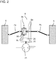
- FIG. 2 shows an example of how the hydraulic motor 21 can be operatively connected to the axle differential 8 of the front axle 4.
- the hydraulic motor 21 is arranged fixed to the chassis.
- a drive shaft 25 driven by the hydraulic motor 21 has at its distal end a drive bevel gear 26 which meshes with the ring gear 8a of the axle differential 8 of the front axle 4.
- the hydraulic motor 21 is integrated in a hydrostatic circuit 20 known per se, for example analogously to that in FIG Figure 1 Example shown, wherein a hydraulic pump 22 is mechanically driven via the mechanical drive train of the vehicle containing the internal combustion engine 9 and is hydraulically connected to the hydraulic motor 21 via fluid lines.
- the ring gear 8a is non-rotatably connected to the cage 8b of the axle differential 8 in a manner known per se.
- the axle differential is designed as a bevel gear differential gear, a pair of axle bevel gears 8d and a pair of differential bevel gears 8c being in engagement with one another.
- the axle bevel gears 8d drive the wheel drive shafts 7a and 7b via the driven shafts 8e of the axle differential 8 and thus transmit the drive power of the hydraulic motor 21 to the front wheels 5.
- the hydraulic motor 21 is thus not arranged coaxially to the axis of rotation R of the outputs 8e of the axle differential 8, but is arranged spatially offset from the axis of rotation R.
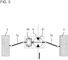
- FIG 3 shows an alternative embodiment.
- the hydraulic motor 21 is not axially offset to the axle differential 8 or to the axis of rotation R of the drives 8e of the axle differential 8 here. Rather, the hydraulic motor 21 is arranged coaxially with the axis of rotation R and drives the cage 8b of the axle differential 8 directly and thus replaces the ring gear 8a.
- the hydraulic motor 21 is designed as a radial piston motor, having an outer, fixed cam ring and an inner, circumferential cylinder housing which is non-rotatably connected to the cage 8b and can thus set it in a rotational movement.
- In the cage 8b there is in turn an axle bolt carrying differential gears, these differential gears 8c meshing with axle shaft gears 8d arranged on the wheel drive shafts 7a, 7b, which are each designed as bevel gears.
- the hydraulic motor 21 can optionally transmit its drive power to the wheels 5 of the second axle 4 with or without a transmission gear which has a defined reduction or transmission ratio.
Landscapes
- Engineering & Computer Science (AREA)
- Chemical & Material Sciences (AREA)
- Combustion & Propulsion (AREA)
- Transportation (AREA)
- Mechanical Engineering (AREA)
- Motor Power Transmission Devices (AREA)
- Arrangement And Driving Of Transmission Devices (AREA)
- Retarders (AREA)
Abstract
Description
- Die Erfindung betrifft ein Kraftfahrzeug mit einem Hilfsantrieb für eine lenkbare Achse.
- Aus dem Stand der Technik sind Nutzfahrzeuge bekannt, die einen hydrostatischen Zusatzantrieb umfassen. Beispielsweise offenbart die Druckschrift
EP 1 886 861 A2 ein Antriebssystem, umfassend eine herkömmliche, mechanische, über eine Antriebswelle angetriebene Hinterachse, wobei die Antriebswelle mit einem Achsdifferential der Hinterachse in Wirkverbindung steht. Das Antriebssystem umfasst ferner zwei mittels hydraulischer Radmotoren RM antreibbare Vorderräder 1, die lenkbar an einer Vorderachse 3 angeordnet sind. Die zwei Radmotoren RM sind in einen geschlossenen hydrostatischen Kreislauf integriert. Dabei wird eine Hauptpumpe mechanisch über den mechanischen Triebstrang des Fahrzeugs angetrieben. Durch ein Steuerventil können die zwei Radmotoren RM zugeschaltet werden. Damit können gegenüber Fahrzeugen mit permanentem Allradantrieb erhebliche Gewichts- und Effizienzvorteile realisiert werden, insbesondere in Fahrzeugen, bei denen der Allradantrieb nur für einen kleinen Teil der tatsächlichen Fahrstrecke benötigt wird. - Aufgrund der hohen Nutzlast sind Baumaschinen, Flurförderfahrzeuge und LKWs in der Regel durch eine starre Achse gekennzeichnet. Leichte Fahrzeuge, insbesondere auch Nutzfahrzeuge mit geringer Nutzlast, zeichnen sich insbesondere bei der Lenkachse durch eine Einzelradaufhängung aus. Entgegen einem durchgängigen Achskörper einer Starrachse, der über Feder-, Dämpfungs- und Führungselemente mit dem Rahmen/Körper des Fahrzeugs verbunden wird, kommen bei der Einzelradaufhängung deutlich leichtere und filigranere Komponenten zum Einsatz. Derartig leichte Fahrzeuge mit Einzelradaufhängung haben in der Regel zwei, in Ausnahmen auch drei Achsen.
- Der Antrieb dieser Fahrzeuge sieht vor, dass zumindest eine Achse von einem mechanischen Antriebsstrang angetrieben wird. Dies kann entweder die Vorderachse oder die Hinterachse sein. Aus der Praxis sind auch derartige Fahrzeuge mit Allradantrieb bekannt. Hierbei wird permanent oder optional die Antriebskraft auf alle Achsen übertragen. Aus der Praxis ist bekannt, dass die Verteilung der Antriebskraft hierbei mechanisch über Verteilergetriebe und/oder Kupplungen sowie Wellen erfolgt. Nachteilig hieran ist, dass hierfür eine zugewiesene Antriebswelle längs der Fahrzeugachse benötigt wird. Daraus ergeben sich auch Einschränkungen bezüglich des Fahrniveaus.
- Die aus dem Stand der Technik bekannten hydrostatisch angetriebenen Radmotoren sind für Fahrzeuge mit Einzelradaufhängung in der Regel unvorteilhaft. Aus fahrdynamischen Gründen ist es wünschenswert, eine möglichst geringe ungefederte Masse des Rades zu haben, was durch die vergleichsweise schweren hydraulischen Radmotoren beeinträchtigt wäre. Ferner ist die Verlegung hydraulischer Leitungen zwischen Radteil und Fahrzeugkörper mit Nachteilen verbunden, da im Allgemeinen nur sehr wenig Bauraum zur Verfügung steht.
- Es ist somit eine Aufgabe der Erfindung, ein verbessertes Fahrzeug bereitzustellen, mit dem Nachteile herkömmlicher Technik vermieden werden können. Die Aufgabe der Erfindung ist es, insbesondere auch für Fahrzeuge mit einer lenkbaren Achse und Einzelradaufhängung eine Antriebsmöglichkeit bereitzustellen, die ein gutes Fahrverhalten ermöglicht und wenig Bauraum beansprucht.
- Diese Aufgaben werden durch ein Kraftfahrzeug mit den Merkmalen des unabhängigen Anspruchs gelöst. Vorteilhafte Ausführungsformen und Anwendungen der Erfindung sind Gegenstand der abhängigen Ansprüche und werden in der folgenden Beschreibung unter teilweiser Bezugnahme auf die Figuren näher erläutert.
- Erfindungsgemäß betrifft die Erfindung ein Nutzfahrzeug mit einer antreibbaren starren ersten Achse, die über einen mechanischen Antriebsstrang, der einen Verbrennungsmotor aufweist, antreibbar ist und/oder angetrieben wird. Das Kraftfahrzeug umfasst ferner eine lenkbare zweite Achse mit Einzelradaufhängung. Die Räder der zweiten Achse sind somit nicht an einer Starrachse angeordnet, sondern können voneinander unabhängig Federbewegungen ausführen. Vorzugsweise ist die erste Achse eine Hinterachse und die zweite Achse eine Vorderachse des Fahrzeugs. Das Nutzfahrzeug hat nur eine starre Achse, d. h., die starre erste Achse ist die einzige starre Achse des Nutzfahrzeugs. Es handelt sich somit um ein leichtes Nutzfahrzeug und nicht um ein schwere Nutzfahrzeug, das in der Regel zwei oder mehr starre Achsen aufweisen. Gemäß allgemeinen Gesichtspunkten der Erfindung ist die zweite Achse von einem hydrostatischen Hilfsantrieb antreibbar und/oder angetrieben, der einen Antriebsmotor in Form eines Hydraulikmotors, auch als Hydromotor bezeichnet, aufweist, der seine Antriebsleistung über ein chassisfestes Getriebe auf die Räder der zweiten Achse aufteilt. Das Getriebe kann also ein nicht-federndes, am Fahrzeugrahmen befestigtes Getriebe sein. Das Getriebe kann als Achsdifferential, weiter vorzugsweise als Kegelrad-Differentialgetriebe ausgeführt sein. Der Antriebsmotor ist somit insbesondere kein Radmotor bzw. Radnabenmotor, sondern ein Antriebsmotor, der z. B. chassisfest angeordnet werden kann. Die lenkbare zweite Achse mit Einzelradaufhängung wird somit nicht durch den Verbrennungsmotor angetrieben, sondern von dem Hilfsantrieb mit dem Antriebsmotor, der mit dem Getriebe wirkverbunden ist. Die Antriebsleistung des hydrostatischen Antriebs wird von einem Nebenabtrieb (engl. power take-off (PTO)) des mechanischen Antriebsstrangs bereitgestellt, also entweder über einen am Verbrennungsmotor vorgesehenen Nebenabtrieb oder über einen am Fahrzeuggetriebe des mechanischen Antriebsstrangs, welches die Motordrehzahl auf die Antriebsdrehzahl übersetzt, vorgesehenen Nebenabtrieb.
- Die erfindungsgemäße Kombination einer mechanisch angetriebenen Starrachse mit einer hydrostatisch angetriebenen Achse mit Einzelradaufhängung bietet insbesondere für leichte Nutzfahrzeuge den Vorzug, dass bei Bedarf ein hohes Drehmoment an eine zusätzliche, hier die Achse mit Einzelradaufhängung, übertragen werden kann, ohne dass dafür eine zugewiesene Antriebswelle längs der Fahrzeuglängsachse benötigt wird. Entsprechend entstehen auch keine Einschränkungen bezüglich des Fahrniveaus durch solch eine sich in Längsrichtung des Fahrzeugs erstreckende Antriebswelle. Ferner kann die Masse des Rades gering gehalten werden, da kein Radnabenmotor vonnöten ist, wodurch fahrdynamisch annähernd die gleichen Randbedingungen vorherrschen wie ohne den Hilfsantrieb.
- Gemäß einer bevorzugten Ausführungsform kann der Antriebsmotor koaxial zu einem Abtrieb des Achsdifferentials, insbesondere zu einer getriebenen Welle des Achsdifferentials, angeordnet sein. Dies bedeutet, dass eine Rotationsachse einer Antriebswelle des Antriebsmotors oder eines anderen rotierenden Teils des Antriebsmotors zur Übertragung der Antriebsleistung der Rotationsachse einer getriebenen Welle des Abtriebs des Achsdifferentials entspricht.
- Gemäß einer bevorzugten Variante dieser Ausführungsform ist ein koaxial zu einem Abtrieb des Achsdifferentials rotierbares Teil des Antriebsmotors mit einem Käfig des Achsdifferentials der zweiten Achse wirkverbunden, insbesondere drehfest verbunden. Der Antriebsmotor kann hierbei somit den Käfig des Achsdifferentials unmittelbar antreiben. Auf ein Tellerrad und auf ein mit dem Tellerrad bewegungsgekoppeltes Antriebskegelrad zum Antrieb des Käfigs des Achsdifferentials kann vorteilhafterweise verzichtet werden. Der Antriebsmotor kann hierbei auf der Welle des Achsdifferentials sitzen. Ein weiterer Vorteil dieser Ausgestaltungsform ist der geringe beanspruchte Bauraum, da oberhalb und unterhalb der zweiten Achse kein oder nur wenig Bauraum zur Anordnung für den Antriebsmotor benötigt wird.
- Bei einer weiteren bevorzugten Ausführungsform ist das Getriebe wiederum als Achsdifferential ausgeführt, wobei der Antriebsmotor nun nicht koaxial zu einem Abtrieb oder nicht koaxial zu einer getriebenen Welle des Achsdifferentials angeordnet ist. Vielmehr ist eine zu der Rotationsachse des Abtriebs der Achsdifferentials räumlich versetzt angeordnete Antriebswelle des Antriebsmotors mit dem Achsdifferential der zweiten Achse wirkverbunden. Der Antriebsmotor kann hierbei über ein mechanisches Getriebe räumlich unabhängig zur Drehrichtung des Achsdifferentials, beispielsweise durch einen Winkeltrieb oder achsparallel, angeordnet sein.
- Diese Ausgestaltungsform bietet den Vorteil, dass keine oder zumindest nur geringe Modifikationen am inneren Aufbau eines an sich üblichen Achsdifferentials der zweiten Achse vonnöten sind, um dieses anstatt von einer Antriebswelle, die vom mechanischen Antriebsstrang angetrieben wird, nun durch den Antriebsmotor des Hilfsantriebs elektrisch oder hydrostatisch anzutreiben.
- Gemäß einer vorteilhaften Variante dieser Ausführungsform ist das Getriebe ein Kegelrad-Differentialgetriebe, aufweisend ein Tellerrad, ein Paar Achskegelräder und ein Paar Ausgleichskegelräder, wobei ein auf einer Antriebswelle des Antriebsmotors sitzendes Antriebsrad mit dem Tellerrad in Eingriff steht.
- Beispielsweise kann der hydrostatische Hilfsantrieb eine vom mechanischen Antriebsstrang angetriebene Hydraulikpumpe aufweisen, die über eine hydraulische Arbeitsleitung mit dem Hydraulikmotor verbunden ist. Die Hydraulikpumpe wird über einen Nebenabtrieb des mechanischen Antriebsstrangs angetrieben, also entweder über einen am Verbrennungsmotor vorgesehenen Nebenabtrieb oder über einen am Fahrzeuggetriebe des mechanischen Antriebsstrangs vorgesehenen Nebenabtrieb. Die Antriebsleistung für den hydrostatischen Antrieb wird somit nicht mechanisch an die Achse mit Einzelradaufhängung übertragen.
- Der Hydraulikmotor kann als Hydraulikmotor mit konstantem oder variablem Schluckvolumen ausgeführt sein. Entsprechend kann die Hydraulikpumpe als Hydraulikpumpe mit konstantem oder variablem Schluckvolumen ausgeführt sein. Die Hydraulikpumpe kann beispielsweise direkt oder über eine Kupplung am Verbrennungsmotor oder am Getriebe angeflanscht sein. Die hydraulischen Arbeitsleitungen zur Energieübertragung zwischen Hydraulikpumpe und Hydraulikmotor können als starre und/oder flexible Leitungen ausgeführt sein.
- Die Antriebskomponenten des hydrostatischen Antriebs lassen sich bedarfsgerecht mit geringem Bauraumbedarf unterbringen, d. h., in Bezug auf den erforderlichen Bauraum reduziert sich der benötigte Installationsraum verglichen mit einem mechanischen Allradantrieb erheblich. Mit einem hydrostatischen Zusatzantrieb können ferner hohe Antriebsdrehmomente bei vergleichsweise geringem Gewicht für die von dem hydrostatischen Zusatzantrieb benötigten Komponenten erzielt werden.
- Gemäß einem weiteren Aspekt kann der Hydraulikmotor mittels einer Kupplung oder eines Freilaufs von dem Achsdifferential der zweiten Achse und/oder von den Radantriebswellen der zweiten Achse an- und abkoppelbar sein. Dadurch kann eine einfache Zuschaltmöglichkeit für den hydrostatischen Hilfsantrieb realisiert werden. Ferner kann ein Übersetzungsgetriebe mit einer vorbestimmten Untersetzung oder Übersetzung, über das der Hydraulikmotor in Wirkverbindung mit den Rädern der zweiten Achse steht, vorgesehen sein zur Anpassung des Betriebsbereichs des Hydraulikmotors an die Raddrehzahl. Wie vorstehend bereits allgemein für den Antriebsmotor des Hilfsantriebs erläutert, kann der Hydraulikmotor entweder koaxial auf der Welle des Achsdifferentials oder über ein mechanisches Getriebe räumlich unabhängig zur Drehrichtung des Achsdifferentials angeordnet sein.
- Bei der ersten Variante kann beispielsweise in dem Käfig des Achsdifferentials ein Ausgleichsräder tragender Achsbolzen gelagert sein, wobei diese Ausgleichsräder mit auf Radantriebswellen angeordneten Achswellenrädern kämmen und diese Räder als Kegelräder ausgebildet sind. Ferner kann der Hydraulikmotor hierbei ein Radialkolbenmotor sein, aufweisend einen äußeren feststehenden Kurvenring und ein inneres, umlaufendes Zylindergehäuse, das drehfest mit dem Käfig verbunden ist, um diesen zu rotieren und darüber die zweite Achse anzutreiben.
- Die zweite Achse kann zwei angeordnete Radantriebswellen aufweisen, die jeweils radseitig mit einem Rad drehfest verbunden sind und an ihrem anderen Ende mit dem Achsdifferential oder dem Hydraulikmotor wirkverbunden sind. Der Antriebsmotor kann beispielsweise in einem mittleren Bereich der zweiten Achse angeordnet sein.
- Bei dem Nutzfahrzeug kann es sich insbesondere um ein Nutzfahrzeug mit einer zulässigen Höchstgeschwindigkeit von über 60 km/h und/oder um ein Nutzfahrzeug, das eine auf mindestens zwei Räder des Nutzfahrzeugs einwirkende Radbremseinrichtung aufweist, handeln.
- Weitere Einzelheiten und Vorteile der Erfindung werden im Folgenden unter Bezug auf die beigefügten Zeichnungen beschrieben. Es zeigen:
- Figur 1
- ein schematisches Blockschaltbild eines Fahrzeugantriebs gemäß einer Ausführungsform der Erfindung;
- Figur 2
- eine lenkbare Vorderachse mit Einzelradaufhängung, angetrieben durch einen Hydromotor gemäß einer Ausführungsform der Erfindung; und
- Figur 3
- eine lenkbare Vorderachse mit Einzelradaufhängung, angetrieben durch einen Hydromotor gemäß einer weiteren Ausführungsform der Erfindung.
- Gleiche oder funktional äquivalente Elemente sind in allen Figuren mit denselben Bezugszeichen bezeichnet.
-
Figur 1 illustriert einen Antrieb 1 für ein Nutzfahrzeug mit zwei angetriebenen Achsen 2, 4. Das Kraftfahrzeug ist vorliegend als Nutzfahrzeug ausgeführt. Das Fahrzeug umfasst einen herkömmlichen mechanischen Antriebsstrang zum Antrieb einer starren Hinterachse 2 des Kraftfahrzeugs. Der mechanische Antriebsstrang umfasst einen Verbrennungsmotor 9, ein Getriebe 10 und eine Antriebswelle 11, die sich in Richtung der Fahrzeuglängsachse erstreckt und die Antriebsleistung an die Hinterachse 2 überträgt. Die Antriebswelle 11 ist mit einem Achsdifferential 12 der Hinterachse 2 verbunden, über das die Antriebsleistung auf die beiden Hinterräder 3 im Wesentlichen zu gleichen Teilen aufgeteilt wird. - Das Fahrzeug umfasst ferner eine lenkbare Vorderachse 4. Die Räder 5 der Vorderachse 4 sind in an sich bekannter Weise mit einer Einzelradaufhängung 6 am Fahrwerk befestigt Die Vorderachse 4 weist somit keine Starrachse auf, d. h., die Vorderachse 4 weist keinen durchgängigen Achskörper, der über Feder-, Dämpfungs- und Führungselemente mit dem Rahmen/Körper des Fahrzeugs verbunden ist, auf.
- Die Vorderachse 4 ist durch einen Hydraulikmotor 21 (auch als Hydromotor bezeichnet) eines hydrostatischen Hilfsantriebs 20 antreibbar. Hierbei ist der Hydraulikmotor 21 mit einem Achsdifferential 8 der Vorderachse 4 wirkverbunden. Die beiden Abtriebe des Achsdifferentials in Form der beiden Abtriebswellen 8e sind jeweils mit einer der Radantriebswellen 7a, 7b drehfest verbunden. Die Rotationsachse R der Abtriebe bzw. Abtriebswellen 8e ist durch die gestrichelte Linie R dargestellt.
- Der Hydraulikmotor 21 ist in einen an sich bekannten geschlossenen hydrostatischen Kreislauf integriert, wobei eine Hydropumpe 22 mechanisch über den mechanischen Antriebsstrang des Fahrzeugs angetrieben wird und über Fluidleitungen 23, 24 hydraulisch mit dem Hydraulikmotor 21 zur Energieübertragung verbunden ist. Eine der Fluidleitungen 23, 24 bildet dabei einen ersten Ast zur Ausbildung eines Vorlaufs, während die andere Fluidleitung den zweiten Ast bildet und damit den Rücklauf des Hydraulikkreislaufs. Der Hydraulikmotor und die Hydraulikpumpe 22 können mit konstantem oder variablem Schluckvolumen ausgeführt sein. Die Hydraulikpumpe kann über eine Kupplung 14 und eine Nebenabtriebswelle 13 an einem Nebenabtrieb des Verbrennungsmotors 9 oder, wie in
Figur 1 dargestellt, an einem Nebenabtrieb am Fahrzeuggetriebe 10 angeflanscht sein. Ferner kann eine Speisepumpe (nicht gezeigt) vorgesehen sein, um auftretende interne und externe Lekagemengen zu kompensieren. Unter externen Lekagemengen versteht man im Allgemeinen Mengen, die mit dem bloßen Auge nicht erkennbar sind. Die Speisepumpe ist in diesem Fall über eine Hydraulikleitung mit einem Vorrat (Speicher) an Hydraulikflüssigkeit (nicht gezeigt) verbunden. Der Hydraulikmotor 21 und die Hydraulikpumpe 22 können jeweils als hydrostatische Radialkolbenmaschinen ausgebildet sein. -
Figur 2 zeigt ein Beispiel, wie der Hydraulikmotor 21 mit dem Achsdifferential 8 der Vorderachse 4 wirkverbunden sein kann. Der Hydraulikmotor 21 ist chassisfest angeordnet. Gemäß der inFigur 2 gezeigten Ausführungsvariante weist eine vom Hydraulikmotor 21 angetriebene Antriebswelle 25 an ihrem distalem Ende ein Antriebskegelrad 26 auf, das mit dem Tellerrad 8a des Achsdifferentials 8 der Vorderachse 4 kämmt. Der Hydromotor 21 ist in einen an sich bekannten hydrostatischen Kreislauf 20 integriert, zum Beispiel analog zu dem inFigur 1 gezeigten Beispiel, wobei eine Hydraulikpumpe 22 mechanisch über den die Brennkraftmaschine 9 enthaltenen mechanischen Antriebsstrang des Fahrzeugs angetrieben wird und über Fluidleitungen hydraulisch mit dem Hydraulikmotor 21 verbunden ist. - Das Tellerrad 8a ist in an sich bekannter Weise drehfest mit dem Käfig 8b des Achsdifferentials 8 verbunden. Das Achsdifferential ist als Kegelrad-Differentialgetriebe ausgeführt, wobei ein Paar Achskegelräder 8d und ein Paar Ausgleichskegelräder 8c miteinander in Eingriff stehen. Die Achskegelräder 8d treiben über die getriebenen Wellen 8e des Achsdifferentials 8 die Radantriebswellen 7a und 7b an und übertragen so die Antriebsleistung des Hydraulikmotors 21 an die Vorderräder 5.
- Gemäß der in
Figur 2 gezeigten Ausführungsvariante ist der Hydraulikmotor 21 somit nicht koaxial zur Rotationsachse R der Abtriebe 8e des Achsdifferentials 8 angeordnet, sondern räumlich versetzt zu der Rotationsachse R angeordnet. -
Figur 3 zeigt eine alternative Ausführungsform. Eine Besonderheit der inFigur 3 gezeigten Ausführungsform liegt darin, dass der Hydraulikmotor 21 hier nicht axial versetzt zum Achsdifferential 8 bzw. zu der Rotationsachse R der Abtriebe 8e des Achsdifferentials 8 angeordnet ist. Der Hydraulikmotor 21 ist vielmehr koaxial zur Rotationsachse R angeordnet und treibt den Käfig 8b des Achsdifferentials 8 direkt an und ersetzt somit das Tellerrad 8a. Der Hydraulikmotor 21 ist als Radialkolbenmotor ausgeführt, aufweisend einen äußeren, feststehenden Kurvenring und ein inneres, umlaufendes Zylindergehäuse, das drehfest mit dem Käfig 8b verbunden ist und diesen somit in eine Rotationsbewegung versetzen kann. In dem Käfig 8b ist wiederum ein Ausgleichsräder tragender Achsbolzen gelagert, wobei diese Ausgleichsräder 8c mit auf den Radantriebswellen 7a, 7b angeordneten Achswellenrädern 8d kämmen, die jeweils als Kegelräder ausgebildet sind. - Der Hydromotor 21 kann gemäß den gezeigten Ausführungsvarianten wahlweise mit oder ohne ein Übersetzungsgetriebe, das eine definierte Untersetzung oder Übersetzung aufweist, seine Antriebsleistung auf die Räder 5 der zweiten Achse 4 übertragen.
- Obwohl die Erfindung unter Bezugnahme auf bestimmte Ausführungsbeispiele beschrieben worden ist, ist es für einen Fachmann ersichtlich, dass verschiedene Änderungen ausgeführt werden können und Äquivalente als Ersatz verwendet werden können, ohne den Bereich der Erfindung zu verlassen. Zusätzlich können viele Modifikationen ausgeführt werden, ohne den zugehörigen Bereich zu verlassen. Folglich soll die Erfindung nicht auf die offenbarten Ausführungsbeispiele begrenzt sein, sondern soll alle Ausführungsbeispiele umfassen, die in den Bereich der beigefügten Patentansprüche fallen. Insbesondere beansprucht die Erfindung auch Schutz für den Gegenstand und die Merkmale der Unteransprüche unabhängig von den in Bezug genommenen Ansprüchen.
-
- 1
- Antrieb
- 2
- Erste Achse, insbesondere Hinterachse
- 3
- Hinterräder
- 4
- Lenkbare zweite Achse mit Einzelradaufhängung, insbesondere Vorderachse
- 5
- Vorderräder
- 6
- Einzelradaufhängung
- 7a, 7b
- Radantriebsachsen
- 8
- Achsendifferential
- 8a
- Tellerrad
- 8b
- Käfig
- 8c
- Ausgleichskegelrad
- 8d
- Achskegelrad
- 8e
- Abtrieb des Achsdifferentials, z. B. getriebene Welle
- 9
- Verbrennungsmotor
- 10
- Getriebe
- 11
- Antriebswelle
- 12
- Achsdifferential
- 13
- Abtrieb
- 14
- Kupplung
- 20
- Hydrostatischer Kreislauf
- 21
- Hydraulikmotor
- 22
- Hydraulikpumpe
- 23
- Hydraulikleitung
- 24
- Hydraulikleitung
- 25
- Antriebswelle des Hydraulikmotors
- 26
- Antriebskegelrad
- R
- Rotationsachse der Abtriebe des Achsdifferentials
Claims (10)
- Kraftfahrzeug, nämlich ein Nutzfahrzeug, mit einer antreibbaren starren ersten Achse (2), die über einen mechanischen, einen Verbrennungsmotor (9) aufweisenden Antriebsstrang (9, 10, 11, 12) antreibbar und/oder angetrieben ist, und einer lenkbaren zweiten Achse (4) mit Einzelradaufhängung, wobei die zweite Achse (4) von einem hydrostatischen Hilfsantrieb (20) antreibbar und/oder angetrieben ist, dessen Antriebsleistung über einen am Verbrennungsmotor vorgesehenen Nebenabtrieb oder einen am Fahrzeuggetriebe des mechanischen Antriebsstrangs, welches die Motordrehzahl auf die Antriebsdrehzahl übersetzt, vorgesehenen Nebenabtrieb bereitgestellt wird, wobei der Hilfsantrieb einen Hydraulikmotor (21) aufweist, der seine Antriebsleistung über ein chassisfestes Getriebe auf die Räder (5) der zweiten Achse (4) aufteilt, wobei die starre erste Achse die einzige starre Achse des Nutzfahrzeugs ist.
- Kraftfahrzeug nach Anspruch 1, wobei das Getriebe ein Achsdifferential (8) ist und der Antriebsmotor koaxial zu einem Abtrieb (8e) des Achsdifferentials (8) angeordnet ist.
- Kraftfahrzeug nach Anspruch 2, wobei ein koaxial zum Abtrieb (8) des Achsdifferentials (8) rotierbares Teil des Antriebsmotors (21) mit einem Käfig (8b) des Achsdifferentials (8) der zweiten Achse (4) wirkverbunden ist.
- Kraftfahrzeug nach Anspruch 1, wobei das Getriebe ein Achsdifferential (8) ist und wobei der Antriebsmotor nicht koaxial zu einem Abtrieb (8e) des Achsdifferentials (8) angeordnet ist und eine Antriebswelle (25) des Antriebsmotors (21) mit dem Achsdifferential (8) der zweiten Achse (4) wirkverbunden ist.
- Kraftfahrzeug nach Anspruch 1 oder 4, wobei das Getriebe ein Kegelraddifferentialgetriebe (8) ist, aufweisend ein Tellerrad (8a), ein Paar Achskegelräder (8d) und ein Paar Ausgleichskegelräder (8c), wobei ein auf einer Antriebswelle (17) des Antriebsmotors (21) sitzendes Antriebsrad (26) mit dem Tellerrad (8a) in Eingriff steht.
- Kraftfahrzeug nach einem der vorhergehenden Ansprüche, wobei der hydrostatische Hilfsantrieb (20) eine vom mechanischen Antriebsstrang (9, 10, 11, 12) über den Nebenabtrieb des Verbrennungsmotors oder des Fahrzeuggetriebes angetriebene Hydraulikpumpe (22) aufweist, die über hydraulische Arbeitsleitungen (23, 24) mit dem Hydraulikmotor (21) verbunden ist.
- Kraftfahrzeug nach Anspruch 4 oder 5, wobei der Hydraulikmotor (21) mittels einer Kupplung oder eines Freilaufs von dem Achsdifferential (8) der zweiten Achse (4) und/oder den Radantriebswellen (7a, 7b) der zweiten Achse (4) an- und abkoppelbar ist.
- Kraftfahrzeug nach einem der vorhergehenden Ansprüche, gekennzeichnet durch ein Übersetzungsgetriebe mit einer vorbestimmten Untersetzung oder Übersetzung, über das der Hydraulikmotor (21) in Wirkverbindung mit den Rädern (5) der zweiten Achse (4) steht.
- Kraftfahrzeug nach einem der Ansprüche 6 bis 8, wenn abhängig von Anspruch 3, wobei in dem Käfig (15) des Achsdifferentials ein Ausgleichsräder tragender Achsbolzen gelagert ist, wobei diese Ausgleichsräder mit auf Radantriebswellen angeordneten Achswellenrädern kämmen und diese Räder als Kegelräder ausgebildet sind; und wobei der Hydraulikmotor ein Radialkolbenmotor ist, aufweisend einen äußeren, feststehenden Kurvenring und ein inneres, umlaufendes Zylindergehäuse, das drehfest mit dem Käfig verbunden ist.
- Kraftfahrzeug nach einem der vorhergehenden Ansprüche, wobei das Kraftfahrzeug ein leichtes Nutzfahrzeug ist.
Applications Claiming Priority (1)
| Application Number | Priority Date | Filing Date | Title |
|---|---|---|---|
| DE102018124014.7A DE102018124014A1 (de) | 2018-09-28 | 2018-09-28 | Kraftfahrzeug mit einem Hilfsantrieb für eine lenkbare Achse |
Publications (2)
| Publication Number | Publication Date |
|---|---|
| EP3628525A1 true EP3628525A1 (de) | 2020-04-01 |
| EP3628525B1 EP3628525B1 (de) | 2022-02-23 |
Family
ID=68069580
Family Applications (1)
| Application Number | Title | Priority Date | Filing Date |
|---|---|---|---|
| EP19199616.4A Active EP3628525B1 (de) | 2018-09-28 | 2019-09-25 | Kraftfahrzeug mit einem hilfsantrieb für eine lenkbare achse |
Country Status (2)
| Country | Link |
|---|---|
| EP (1) | EP3628525B1 (de) |
| DE (1) | DE102018124014A1 (de) |
Cited By (1)
| Publication number | Priority date | Publication date | Assignee | Title |
|---|---|---|---|---|
| FR3123832A1 (fr) * | 2021-06-11 | 2022-12-16 | Psa Automobiles Sa | Véhicule à circuit de transmission hydraulique contrôlé pour la répartition de couple entre trains |
Citations (5)
| Publication number | Priority date | Publication date | Assignee | Title |
|---|---|---|---|---|
| EP1318064A2 (de) * | 2001-12-04 | 2003-06-11 | DaimlerChrysler AG | Modular aufgebauter Tragrahmen für ein Nutzfahrzeug |
| EP1886861A2 (de) | 2006-08-11 | 2008-02-13 | MAN Nutzfahrzeuge Österreich AG | Quersperre für MAN-Hydrodrive |
| DE102011118111A1 (de) * | 2011-11-09 | 2012-05-24 | Daimler Ag | Antriebsstrang für einen Kraftwagen |
| WO2017081164A1 (fr) * | 2015-11-10 | 2017-05-18 | Poclain Hydraulics Industrie | Procédé d'engagement de l'assistance hydraulique |
| US20180065479A1 (en) * | 2015-03-13 | 2018-03-08 | Poclain Hydraulics Industrie | Vehicle-mounted hydraulic assistance device and method for evacuating such a device |
Family Cites Families (1)
| Publication number | Priority date | Publication date | Assignee | Title |
|---|---|---|---|---|
| JP3430754B2 (ja) * | 1995-11-29 | 2003-07-28 | 日産自動車株式会社 | 四輪駆動車 |
-
2018
- 2018-09-28 DE DE102018124014.7A patent/DE102018124014A1/de not_active Withdrawn
-
2019
- 2019-09-25 EP EP19199616.4A patent/EP3628525B1/de active Active
Patent Citations (5)
| Publication number | Priority date | Publication date | Assignee | Title |
|---|---|---|---|---|
| EP1318064A2 (de) * | 2001-12-04 | 2003-06-11 | DaimlerChrysler AG | Modular aufgebauter Tragrahmen für ein Nutzfahrzeug |
| EP1886861A2 (de) | 2006-08-11 | 2008-02-13 | MAN Nutzfahrzeuge Österreich AG | Quersperre für MAN-Hydrodrive |
| DE102011118111A1 (de) * | 2011-11-09 | 2012-05-24 | Daimler Ag | Antriebsstrang für einen Kraftwagen |
| US20180065479A1 (en) * | 2015-03-13 | 2018-03-08 | Poclain Hydraulics Industrie | Vehicle-mounted hydraulic assistance device and method for evacuating such a device |
| WO2017081164A1 (fr) * | 2015-11-10 | 2017-05-18 | Poclain Hydraulics Industrie | Procédé d'engagement de l'assistance hydraulique |
Non-Patent Citations (1)
| Title |
|---|
| REUTER M ET AL: "DIE BREMSANLAGE DER NEUEN TRANSPORTER-GENERATION SPRINTER VON MERCEDES-BENZ", ATZ, SPRINGER VIEWEG, DE, vol. 98, no. 1, 1 January 1996 (1996-01-01), pages - 35, XP000548181, ISSN: 0001-2785 * |
Cited By (1)
| Publication number | Priority date | Publication date | Assignee | Title |
|---|---|---|---|---|
| FR3123832A1 (fr) * | 2021-06-11 | 2022-12-16 | Psa Automobiles Sa | Véhicule à circuit de transmission hydraulique contrôlé pour la répartition de couple entre trains |
Also Published As
| Publication number | Publication date |
|---|---|
| EP3628525B1 (de) | 2022-02-23 |
| DE102018124014A1 (de) | 2020-04-02 |
Similar Documents
| Publication | Publication Date | Title |
|---|---|---|
| DE102006038358B4 (de) | Achsantriebseinheit für einen Antriebsstrang | |
| DE102005004290B4 (de) | Getriebemodul zur variablen Drehmomentverteilung | |
| EP3165395B1 (de) | Nutzfahrzeug, insbesondere lkw, mit mindestens einem doppelachsaggregat | |
| EP0414722B1 (de) | Allradgetriebener ackerschlepper | |
| DE10310713B4 (de) | Achsdifferential mit elektronischem Achswellenmanagement | |
| EP1733156A2 (de) | Verteilergetriebe | |
| EP3027455A1 (de) | Antriebsstrang eines kraftfahrzeugs | |
| EP2314472A1 (de) | Getriebeanordnung für ein Fahrzeug und Getriebe mit der Getriebeanordnung | |
| DE4323539C1 (de) | Radlagereinheit eines Kraftfahrzeugs | |
| EP0201493B1 (de) | Mehrachsfahrzeug mit einzelradantrieben | |
| DE2335629B2 (de) | Hydrostatisch-mechanischer antrieb fuer land- und bauwirtschaftlich genutzte fahrzeuge | |
| EP3628525B1 (de) | Kraftfahrzeug mit einem hilfsantrieb für eine lenkbare achse | |
| DE102013203567B4 (de) | Doppelrad-Antriebsmodul und Schwerlastfahrzeug | |
| DE102009055867A1 (de) | Differenzial | |
| EP3888981B1 (de) | Achsantrieb | |
| DE102021208545A1 (de) | Getriebe für ein Fahrzeug sowie Antriebsstrang mit einem solchen Getriebe | |
| WO2012146352A1 (de) | Antriebsvorrichtung für ein front-, heck- oder allradgetriebenes kraftfahrzeug | |
| DE3411746C1 (de) | Allradantrieb fuer Kraftfahrzeuge | |
| EP0491221B1 (de) | Drehmomentenübertragende Gelenkverbindung, vorzugsweise für Antriebshalbwellen oder mehrteilige Kardanwellen von Kraftfahrzeugen | |
| DE3913487A1 (de) | Allradgetriebener ackerschlepper | |
| DE102015210227A1 (de) | Antriebsstrang | |
| DE102019205987B4 (de) | Elektrischer Achsantrieb für ein Fahrzeug | |
| DE102015222003A1 (de) | Antriebseinheit, Arbeitsmaschine und Anbaugerät | |
| DE102021213063A1 (de) | Lenkantrieb für eine Lenkachse eines lenkbaren Fahrzeugs, Lenkachse und Flurförderzeug | |
| DE102019006267A1 (de) | Antriebswellenvorrichtung für einen Kraftwagen |
Legal Events
| Date | Code | Title | Description |
|---|---|---|---|
| PUAI | Public reference made under article 153(3) epc to a published international application that has entered the european phase |
Free format text: ORIGINAL CODE: 0009012 |
|
| STAA | Information on the status of an ep patent application or granted ep patent |
Free format text: STATUS: THE APPLICATION HAS BEEN PUBLISHED |
|
| AK | Designated contracting states |
Kind code of ref document: A1 Designated state(s): AL AT BE BG CH CY CZ DE DK EE ES FI FR GB GR HR HU IE IS IT LI LT LU LV MC MK MT NL NO PL PT RO RS SE SI SK SM TR |
|
| AX | Request for extension of the european patent |
Extension state: BA ME |
|
| STAA | Information on the status of an ep patent application or granted ep patent |
Free format text: STATUS: REQUEST FOR EXAMINATION WAS MADE |
|
| 17P | Request for examination filed |
Effective date: 20200923 |
|
| RBV | Designated contracting states (corrected) |
Designated state(s): AL AT BE BG CH CY CZ DE DK EE ES FI FR GB GR HR HU IE IS IT LI LT LU LV MC MK MT NL NO PL PT RO RS SE SI SK SM TR |
|
| STAA | Information on the status of an ep patent application or granted ep patent |
Free format text: STATUS: EXAMINATION IS IN PROGRESS |
|
| 17Q | First examination report despatched |
Effective date: 20210212 |
|
| GRAP | Despatch of communication of intention to grant a patent |
Free format text: ORIGINAL CODE: EPIDOSNIGR1 |
|
| STAA | Information on the status of an ep patent application or granted ep patent |
Free format text: STATUS: GRANT OF PATENT IS INTENDED |
|
| INTG | Intention to grant announced |
Effective date: 20211202 |
|
| GRAS | Grant fee paid |
Free format text: ORIGINAL CODE: EPIDOSNIGR3 |
|
| GRAA | (expected) grant |
Free format text: ORIGINAL CODE: 0009210 |
|
| STAA | Information on the status of an ep patent application or granted ep patent |
Free format text: STATUS: THE PATENT HAS BEEN GRANTED |
|
| AK | Designated contracting states |
Kind code of ref document: B1 Designated state(s): AL AT BE BG CH CY CZ DE DK EE ES FI FR GB GR HR HU IE IS IT LI LT LU LV MC MK MT NL NO PL PT RO RS SE SI SK SM TR |
|
| REG | Reference to a national code |
Ref country code: GB Ref legal event code: FG4D Free format text: NOT ENGLISH |
|
| REG | Reference to a national code |
Ref country code: CH Ref legal event code: EP |
|
| REG | Reference to a national code |
Ref country code: AT Ref legal event code: REF Ref document number: 1470201 Country of ref document: AT Kind code of ref document: T Effective date: 20220315 |
|
| REG | Reference to a national code |
Ref country code: IE Ref legal event code: FG4D Free format text: LANGUAGE OF EP DOCUMENT: GERMAN |
|
| REG | Reference to a national code |
Ref country code: DE Ref legal event code: R096 Ref document number: 502019003473 Country of ref document: DE |
|
| REG | Reference to a national code |
Ref country code: SE Ref legal event code: TRGR |
|
| REG | Reference to a national code |
Ref country code: NL Ref legal event code: FP |
|
| REG | Reference to a national code |
Ref country code: LT Ref legal event code: MG9D |
|
| PG25 | Lapsed in a contracting state [announced via postgrant information from national office to epo] |
Ref country code: RS Free format text: LAPSE BECAUSE OF FAILURE TO SUBMIT A TRANSLATION OF THE DESCRIPTION OR TO PAY THE FEE WITHIN THE PRESCRIBED TIME-LIMIT Effective date: 20220223 Ref country code: PT Free format text: LAPSE BECAUSE OF FAILURE TO SUBMIT A TRANSLATION OF THE DESCRIPTION OR TO PAY THE FEE WITHIN THE PRESCRIBED TIME-LIMIT Effective date: 20220623 Ref country code: NO Free format text: LAPSE BECAUSE OF FAILURE TO SUBMIT A TRANSLATION OF THE DESCRIPTION OR TO PAY THE FEE WITHIN THE PRESCRIBED TIME-LIMIT Effective date: 20220523 Ref country code: LT Free format text: LAPSE BECAUSE OF FAILURE TO SUBMIT A TRANSLATION OF THE DESCRIPTION OR TO PAY THE FEE WITHIN THE PRESCRIBED TIME-LIMIT Effective date: 20220223 Ref country code: HR Free format text: LAPSE BECAUSE OF FAILURE TO SUBMIT A TRANSLATION OF THE DESCRIPTION OR TO PAY THE FEE WITHIN THE PRESCRIBED TIME-LIMIT Effective date: 20220223 Ref country code: ES Free format text: LAPSE BECAUSE OF FAILURE TO SUBMIT A TRANSLATION OF THE DESCRIPTION OR TO PAY THE FEE WITHIN THE PRESCRIBED TIME-LIMIT Effective date: 20220223 Ref country code: BG Free format text: LAPSE BECAUSE OF FAILURE TO SUBMIT A TRANSLATION OF THE DESCRIPTION OR TO PAY THE FEE WITHIN THE PRESCRIBED TIME-LIMIT Effective date: 20220523 |
|
| PG25 | Lapsed in a contracting state [announced via postgrant information from national office to epo] |
Ref country code: PL Free format text: LAPSE BECAUSE OF FAILURE TO SUBMIT A TRANSLATION OF THE DESCRIPTION OR TO PAY THE FEE WITHIN THE PRESCRIBED TIME-LIMIT Effective date: 20220223 Ref country code: LV Free format text: LAPSE BECAUSE OF FAILURE TO SUBMIT A TRANSLATION OF THE DESCRIPTION OR TO PAY THE FEE WITHIN THE PRESCRIBED TIME-LIMIT Effective date: 20220223 Ref country code: GR Free format text: LAPSE BECAUSE OF FAILURE TO SUBMIT A TRANSLATION OF THE DESCRIPTION OR TO PAY THE FEE WITHIN THE PRESCRIBED TIME-LIMIT Effective date: 20220524 Ref country code: FI Free format text: LAPSE BECAUSE OF FAILURE TO SUBMIT A TRANSLATION OF THE DESCRIPTION OR TO PAY THE FEE WITHIN THE PRESCRIBED TIME-LIMIT Effective date: 20220223 |
|
| PG25 | Lapsed in a contracting state [announced via postgrant information from national office to epo] |
Ref country code: IS Free format text: LAPSE BECAUSE OF FAILURE TO SUBMIT A TRANSLATION OF THE DESCRIPTION OR TO PAY THE FEE WITHIN THE PRESCRIBED TIME-LIMIT Effective date: 20220623 |
|
| PG25 | Lapsed in a contracting state [announced via postgrant information from national office to epo] |
Ref country code: SM Free format text: LAPSE BECAUSE OF FAILURE TO SUBMIT A TRANSLATION OF THE DESCRIPTION OR TO PAY THE FEE WITHIN THE PRESCRIBED TIME-LIMIT Effective date: 20220223 Ref country code: SK Free format text: LAPSE BECAUSE OF FAILURE TO SUBMIT A TRANSLATION OF THE DESCRIPTION OR TO PAY THE FEE WITHIN THE PRESCRIBED TIME-LIMIT Effective date: 20220223 Ref country code: RO Free format text: LAPSE BECAUSE OF FAILURE TO SUBMIT A TRANSLATION OF THE DESCRIPTION OR TO PAY THE FEE WITHIN THE PRESCRIBED TIME-LIMIT Effective date: 20220223 Ref country code: EE Free format text: LAPSE BECAUSE OF FAILURE TO SUBMIT A TRANSLATION OF THE DESCRIPTION OR TO PAY THE FEE WITHIN THE PRESCRIBED TIME-LIMIT Effective date: 20220223 Ref country code: DK Free format text: LAPSE BECAUSE OF FAILURE TO SUBMIT A TRANSLATION OF THE DESCRIPTION OR TO PAY THE FEE WITHIN THE PRESCRIBED TIME-LIMIT Effective date: 20220223 Ref country code: CZ Free format text: LAPSE BECAUSE OF FAILURE TO SUBMIT A TRANSLATION OF THE DESCRIPTION OR TO PAY THE FEE WITHIN THE PRESCRIBED TIME-LIMIT Effective date: 20220223 |
|
| REG | Reference to a national code |
Ref country code: DE Ref legal event code: R097 Ref document number: 502019003473 Country of ref document: DE |
|
| PG25 | Lapsed in a contracting state [announced via postgrant information from national office to epo] |
Ref country code: AL Free format text: LAPSE BECAUSE OF FAILURE TO SUBMIT A TRANSLATION OF THE DESCRIPTION OR TO PAY THE FEE WITHIN THE PRESCRIBED TIME-LIMIT Effective date: 20220223 |
|
| PLBE | No opposition filed within time limit |
Free format text: ORIGINAL CODE: 0009261 |
|
| STAA | Information on the status of an ep patent application or granted ep patent |
Free format text: STATUS: NO OPPOSITION FILED WITHIN TIME LIMIT |
|
| 26N | No opposition filed |
Effective date: 20221124 |
|
| PG25 | Lapsed in a contracting state [announced via postgrant information from national office to epo] |
Ref country code: SI Free format text: LAPSE BECAUSE OF FAILURE TO SUBMIT A TRANSLATION OF THE DESCRIPTION OR TO PAY THE FEE WITHIN THE PRESCRIBED TIME-LIMIT Effective date: 20220223 |
|
| PG25 | Lapsed in a contracting state [announced via postgrant information from national office to epo] |
Ref country code: MC Free format text: LAPSE BECAUSE OF FAILURE TO SUBMIT A TRANSLATION OF THE DESCRIPTION OR TO PAY THE FEE WITHIN THE PRESCRIBED TIME-LIMIT Effective date: 20220223 |
|
| REG | Reference to a national code |
Ref country code: CH Ref legal event code: PL |
|
| REG | Reference to a national code |
Ref country code: BE Ref legal event code: MM Effective date: 20220930 |
|
| PG25 | Lapsed in a contracting state [announced via postgrant information from national office to epo] |
Ref country code: LU Free format text: LAPSE BECAUSE OF NON-PAYMENT OF DUE FEES Effective date: 20220925 |
|
| PG25 | Lapsed in a contracting state [announced via postgrant information from national office to epo] |
Ref country code: LI Free format text: LAPSE BECAUSE OF NON-PAYMENT OF DUE FEES Effective date: 20220930 Ref country code: IE Free format text: LAPSE BECAUSE OF NON-PAYMENT OF DUE FEES Effective date: 20220925 Ref country code: CH Free format text: LAPSE BECAUSE OF NON-PAYMENT OF DUE FEES Effective date: 20220930 |
|
| PG25 | Lapsed in a contracting state [announced via postgrant information from national office to epo] |
Ref country code: BE Free format text: LAPSE BECAUSE OF NON-PAYMENT OF DUE FEES Effective date: 20220930 |
|
| PGFP | Annual fee paid to national office [announced via postgrant information from national office to epo] |
Ref country code: NL Payment date: 20230926 Year of fee payment: 5 Ref country code: IT Payment date: 20230920 Year of fee payment: 5 |
|
| PGFP | Annual fee paid to national office [announced via postgrant information from national office to epo] |
Ref country code: SE Payment date: 20230926 Year of fee payment: 5 Ref country code: FR Payment date: 20230926 Year of fee payment: 5 Ref country code: DE Payment date: 20230928 Year of fee payment: 5 |
|
| PG25 | Lapsed in a contracting state [announced via postgrant information from national office to epo] |
Ref country code: HU Free format text: LAPSE BECAUSE OF FAILURE TO SUBMIT A TRANSLATION OF THE DESCRIPTION OR TO PAY THE FEE WITHIN THE PRESCRIBED TIME-LIMIT; INVALID AB INITIO Effective date: 20190925 |
|
| PG25 | Lapsed in a contracting state [announced via postgrant information from national office to epo] |
Ref country code: CY Free format text: LAPSE BECAUSE OF FAILURE TO SUBMIT A TRANSLATION OF THE DESCRIPTION OR TO PAY THE FEE WITHIN THE PRESCRIBED TIME-LIMIT Effective date: 20220223 |