EP1886861A2 - Quersperre für MAN-Hydrodrive - Google Patents
Quersperre für MAN-Hydrodrive Download PDFInfo
- Publication number
- EP1886861A2 EP1886861A2 EP20070015157 EP07015157A EP1886861A2 EP 1886861 A2 EP1886861 A2 EP 1886861A2 EP 20070015157 EP20070015157 EP 20070015157 EP 07015157 A EP07015157 A EP 07015157A EP 1886861 A2 EP1886861 A2 EP 1886861A2
- Authority
- EP
- European Patent Office
- Prior art keywords
- hydraulic
- motor vehicle
- pressure oil
- vehicle according
- circuit
- Prior art date
- Legal status (The legal status is an assumption and is not a legal conclusion. Google has not performed a legal analysis and makes no representation as to the accuracy of the status listed.)
- Granted
Links
- 239000003921 oil Substances 0.000 claims description 68
- 239000010720 hydraulic oil Substances 0.000 claims description 19
- 230000002706 hydrostatic effect Effects 0.000 description 6
- 230000004913 activation Effects 0.000 description 1
- 230000005540 biological transmission Effects 0.000 description 1
- 238000001816 cooling Methods 0.000 description 1
- 230000007547 defect Effects 0.000 description 1
- 238000011161 development Methods 0.000 description 1
- 230000018109 developmental process Effects 0.000 description 1
- 238000006073 displacement reaction Methods 0.000 description 1
- 239000008157 edible vegetable oil Substances 0.000 description 1
- 230000000694 effects Effects 0.000 description 1
- ZZUFCTLCJUWOSV-UHFFFAOYSA-N furosemide Chemical compound C1=C(Cl)C(S(=O)(=O)N)=CC(C(O)=O)=C1NCC1=CC=CO1 ZZUFCTLCJUWOSV-UHFFFAOYSA-N 0.000 description 1
- 230000001771 impaired effect Effects 0.000 description 1
- 238000012423 maintenance Methods 0.000 description 1
- 230000009347 mechanical transmission Effects 0.000 description 1
- 238000010248 power generation Methods 0.000 description 1
- 239000007787 solid Substances 0.000 description 1
- 239000000725 suspension Substances 0.000 description 1
- 238000011144 upstream manufacturing Methods 0.000 description 1
Images


Classifications
-
- B—PERFORMING OPERATIONS; TRANSPORTING
- B60—VEHICLES IN GENERAL
- B60K—ARRANGEMENT OR MOUNTING OF PROPULSION UNITS OR OF TRANSMISSIONS IN VEHICLES; ARRANGEMENT OR MOUNTING OF PLURAL DIVERSE PRIME-MOVERS IN VEHICLES; AUXILIARY DRIVES FOR VEHICLES; INSTRUMENTATION OR DASHBOARDS FOR VEHICLES; ARRANGEMENTS IN CONNECTION WITH COOLING, AIR INTAKE, GAS EXHAUST OR FUEL SUPPLY OF PROPULSION UNITS IN VEHICLES
- B60K17/00—Arrangement or mounting of transmissions in vehicles
- B60K17/04—Arrangement or mounting of transmissions in vehicles characterised by arrangement, location, or kind of gearing
- B60K17/16—Arrangement or mounting of transmissions in vehicles characterised by arrangement, location, or kind of gearing of differential gearing
- B60K17/20—Arrangement or mounting of transmissions in vehicles characterised by arrangement, location, or kind of gearing of differential gearing in which the differential movement is limited
-
- B—PERFORMING OPERATIONS; TRANSPORTING
- B60—VEHICLES IN GENERAL
- B60K—ARRANGEMENT OR MOUNTING OF PROPULSION UNITS OR OF TRANSMISSIONS IN VEHICLES; ARRANGEMENT OR MOUNTING OF PLURAL DIVERSE PRIME-MOVERS IN VEHICLES; AUXILIARY DRIVES FOR VEHICLES; INSTRUMENTATION OR DASHBOARDS FOR VEHICLES; ARRANGEMENTS IN CONNECTION WITH COOLING, AIR INTAKE, GAS EXHAUST OR FUEL SUPPLY OF PROPULSION UNITS IN VEHICLES
- B60K17/00—Arrangement or mounting of transmissions in vehicles
- B60K17/34—Arrangement or mounting of transmissions in vehicles for driving both front and rear wheels, e.g. four wheel drive vehicles
- B60K17/356—Arrangement or mounting of transmissions in vehicles for driving both front and rear wheels, e.g. four wheel drive vehicles having fluid or electric motor, for driving one or more wheels
-
- F—MECHANICAL ENGINEERING; LIGHTING; HEATING; WEAPONS; BLASTING
- F16—ENGINEERING ELEMENTS AND UNITS; GENERAL MEASURES FOR PRODUCING AND MAINTAINING EFFECTIVE FUNCTIONING OF MACHINES OR INSTALLATIONS; THERMAL INSULATION IN GENERAL
- F16H—GEARING
- F16H48/00—Differential gearings
- F16H48/12—Differential gearings without gears having orbital motion
- F16H48/18—Differential gearings without gears having orbital motion with fluid gearing
-
- F—MECHANICAL ENGINEERING; LIGHTING; HEATING; WEAPONS; BLASTING
- F16—ENGINEERING ELEMENTS AND UNITS; GENERAL MEASURES FOR PRODUCING AND MAINTAINING EFFECTIVE FUNCTIONING OF MACHINES OR INSTALLATIONS; THERMAL INSULATION IN GENERAL
- F16H—GEARING
- F16H61/00—Control functions within control units of change-speed- or reversing-gearings for conveying rotary motion ; Control of exclusively fluid gearing, friction gearing, gearings with endless flexible members or other particular types of gearing
- F16H61/38—Control of exclusively fluid gearing
- F16H61/40—Control of exclusively fluid gearing hydrostatic
- F16H61/4035—Control of circuit flow
-
- F—MECHANICAL ENGINEERING; LIGHTING; HEATING; WEAPONS; BLASTING
- F16—ENGINEERING ELEMENTS AND UNITS; GENERAL MEASURES FOR PRODUCING AND MAINTAINING EFFECTIVE FUNCTIONING OF MACHINES OR INSTALLATIONS; THERMAL INSULATION IN GENERAL
- F16H—GEARING
- F16H61/00—Control functions within control units of change-speed- or reversing-gearings for conveying rotary motion ; Control of exclusively fluid gearing, friction gearing, gearings with endless flexible members or other particular types of gearing
- F16H61/38—Control of exclusively fluid gearing
- F16H61/40—Control of exclusively fluid gearing hydrostatic
- F16H61/4078—Fluid exchange between hydrostatic circuits and external sources or consumers
- F16H61/4139—Replenishing or scavenging pumps, e.g. auxiliary charge pumps
-
- F—MECHANICAL ENGINEERING; LIGHTING; HEATING; WEAPONS; BLASTING
- F16—ENGINEERING ELEMENTS AND UNITS; GENERAL MEASURES FOR PRODUCING AND MAINTAINING EFFECTIVE FUNCTIONING OF MACHINES OR INSTALLATIONS; THERMAL INSULATION IN GENERAL
- F16H—GEARING
- F16H61/00—Control functions within control units of change-speed- or reversing-gearings for conveying rotary motion ; Control of exclusively fluid gearing, friction gearing, gearings with endless flexible members or other particular types of gearing
- F16H61/38—Control of exclusively fluid gearing
- F16H61/40—Control of exclusively fluid gearing hydrostatic
- F16H61/44—Control of exclusively fluid gearing hydrostatic with more than one pump or motor in operation
- F16H61/456—Control of the balance of torque or speed between pumps or motors
-
- B—PERFORMING OPERATIONS; TRANSPORTING
- B60—VEHICLES IN GENERAL
- B60K—ARRANGEMENT OR MOUNTING OF PROPULSION UNITS OR OF TRANSMISSIONS IN VEHICLES; ARRANGEMENT OR MOUNTING OF PLURAL DIVERSE PRIME-MOVERS IN VEHICLES; AUXILIARY DRIVES FOR VEHICLES; INSTRUMENTATION OR DASHBOARDS FOR VEHICLES; ARRANGEMENTS IN CONNECTION WITH COOLING, AIR INTAKE, GAS EXHAUST OR FUEL SUPPLY OF PROPULSION UNITS IN VEHICLES
- B60K7/00—Disposition of motor in, or adjacent to, traction wheel
- B60K7/0015—Disposition of motor in, or adjacent to, traction wheel the motor being hydraulic
Definitions
- the invention relates to a motor vehicle, in particular commercial vehicle, with at least one steerable front axle and at least one rear axle, of which at least one rear axle can be driven via a mechanical drive train and with a, a control block having hydraulic circuit which is provided for feeding of hydraulic single-wheel motors.
- the Einzelradmotoren are arranged on at least two steerable front wheels at least one of the front axles and serve to drive them.
- a drive device for motor vehicles in particular for commercial vehicles is known, which has a mechanical drive connection between a vehicle engine and the vehicle wheels of one of the vehicle axles.
- the drive device moreover has an additional drive which can be switched on and off for the vehicle wheels of at least one other vehicle axle, which is designed as a hydrostatic single-wheel drive and in which the drive wheels are each assigned a hydraulic motor as an additional drive motor.
- the hydraulic motor is drivably connected to at least one hydraulic pump driven by the vehicle engine, wherein a feed pump which can be driven independently of the hydraulic pump by the vehicle engine or another vehicle-internal energy source is provided.
- the hydrostatic single-wheel drive to which the document refers, has the property that the hydraulic circuit directs the drive power in the worst case to that person hydrostatically driven wheel, which has the lowest traction. It would therefore be desirable to further develop the drive device in such a way that the drive via the hydrostatically driven single wheels is maintained even with partial or complete loss of traction of one of the individual wheels.
- This object is achieved in that is arranged in the hydraulic circuit for the at least two steerable front wheels of the front axles acting as a locking differential, controlled by the control block pressure oil distributor.
- the motor vehicle according to the invention in particular commercial vehicle has two or more axles, of which at least one rear axle with a mechanical Powertrain is driven. Of the at least two axes of the motor vehicle, the wheels of at least one axis are steerable.
- the rear axle is driven by the mechanical drive train and the front axle is steerable. It is conceivable that such a commercial vehicle mainly on solid ground z. B. a road with sufficient traction is moved. Will now the commercial vehicle z. B. off a paved road on a ground with insufficient traction moves, or is the underground z. B.
- the motor vehicle handlebar has the ability to provide in addition to the normally driven rear axle via a hydrostatic independent drive and the steerable wheels of the motor vehicle with its own drive. If the case occurs that when one of the front wheels steers the front steerable wheels, the traction with respect to the ground loses all or part of the steerable front wheels, the hydrostatic independent drive known from the prior art is characterized in that the hydrostatic drive power to the extent and extent, how one of the two hydrostatically driven single wheels loses traction, on which the wheel with limited traction passes.
- the invention now offers the advantage that by a arranged in the hydraulic circuit control block also arranged in the hydraulic circuit pressure oil distributor the amount of hydraulic oil automatically and / or manually selectable, so distributed to the hydrostatically driven front wheels that also has sufficient traction hydrostatically driven single wheel sufficient drive power so that the drive of the commercial vehicle can be continued. It is also conceivable to distribute the driving force on the distribution of the amount of oil in any other ratio to the hydraulically driven single-wheel engines. It is conceivable that the hydraulic single-wheel motors are parallel constant-flow hydraulic motors integrated in the hubs of the steered front axles. A wheel-driven constant oil pump can be connected via a mechanical translation fixed to the rear axle.
- Both the mechanical and the hydraulic total ratio is designed so that there is synchronization between the front and rear axles.
- the rear axle is conventionally driven via the engine, transmission, propeller shaft and a rear differential.
- the constant oil pump By driving the rear wheels, the constant oil pump generates a hydraulic flow in the hydraulic circuit, which is fed to the hydraulically driven single wheel motors.
- the drive of the constant oil pump z. B. be switched via a multi-plate power shift clutch. It is advantageous that the distribution of the driving force through the hydraulic circuit in the even split ratio 50:50 can be made to the hydraulic single-wheel motors, so that the pressure oil distributor has the functional effect of a differential lock.
- the distribution of the drive power to the hydraulic single-wheel motors is pressure and viscosity independent. It is advantageous that high pressure hoses can be used for the hydraulic circuit to reduce pressure peaks and to protect against leaks. Another advantage is that the steering angle of the motor vehicle according to the invention compared to a conventional motor vehicle from the prior art is not impaired.
- the motor vehicle according to the invention can likewise be equipped with one or more rigid axles or with independent wheel suspension.
- the hydraulic circuit comprises a hydraulic supply and a hydraulic return, which connect the pressure oil distributor with the individual motors.
- only the hydraulic inlet is connected to the pressure oil distributor, while the hydraulic return, bypassing the pressure oil distributor is directly connected to the control block.
- the pressure oil distributor acts in terms of the hydraulic circuit in forward motion as a flow divider.
- the pressure oil distributor acts in terms of the hydraulic circuit in reverse drive as Summenteiler.
- the hydrostatic single-wheel engines thus work in both directions.
- the oil flow direction in the closed hydraulic circuit is determined by the direction of travel of the rear axle.
- the constant oil pump and the hydraulic single-wheel motors are designed as double-acting suction-pressure units.
- Another embodiment of the invention shows that the initially supplied hydraulic oil flow to the two connected single-wheel engines in terms of the same and different amounts of hydraulic oil is divisible.
- Another embodiment of the invention is characterized in that the hydraulic circuit is a high-pressure circuit.
- the distribution of the high pressure oil through the pressure oil distributor on the at least two steerable front wheels ensures, as required, an equal or different distribution of the driving force on the hydraulically driven steerable front wheels.
- a further embodiment of the invention provides that a connection for a feed circuit is provided in the hydraulic circuit.
- the connection can be made as required in a hydraulic line and / or z. B. lead into the control block or the pressure oil distributor.
- the feed circuit ensures a filling or emptying of the hydraulic circuit z. B. in case of maintenance.
- the feed circuit is a low pressure circuit. It is conceivable that the hydraulic circuit is supplied as a high-pressure circuit from a motor-driven feed pump via a feed circuit.
- the hydraulic circuit can be removed via an exit valve oil, which is passed through an oil cooling to an oil reservoir.
- a flow filter, z. B. be arranged a pressure filter.
- make-up valves can be arranged to compensate for filling defects or prevent cavitation when cornering.
- the pressure oil distributor on an integrated freewheel lock circuit.
- the pressure oil distributor is switched on and off.
- the pressure oil distributor can be switched off as a function of a predetermined driving speed. It is conceivable that the connection and disconnection of the pressure oil distributor from the motor vehicle handlebar via an on / off switch and is additionally controlled via a CAN-capable electronic control unit. The electronic control gives the switching on and off of the pressure oil distributor due to a programmed Switching program free. It is also advantageous that input signals such as the engine speed, the vehicle speed, the wheel speeds of front and rear axles, the feed pressure, the oil temperature and z. B. the ABS system in the regulation of the pressure oil distributor can be considered by the control block. It is also conceivable that the control block switches the supply circuit on and off. To protect against over-rotation of the constant oil pump z. B.
- the control block when exceeding predetermined parameters such. As the driving speed, the oil temperature, the failure of feed pressure, the present implausibility of the wheel speeds of front axle / s and rear axle / s or on activation of the anti-lock braking system can be switched on.
- a check valve is arranged in the hydraulic circuit.
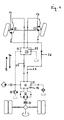
- Fig. 1 shows a schematic representation of a front axle 1 with hydraulically driven steerable front wheels 2 and a hydraulic circuit 3.
- reference numeral 4 is a denotes the rear axle, on which the rear wheels 5 are arranged.
- the hydraulic circuit 3 has a hydraulic constant pump 7, which is wheel-driven in the example of FIG. 1 and is connected to the wheels 5 of the rear axle 4 via a fixed mechanical transmission. Between the rear axle 4 and the Hydrokonstantpumpe 7, a clutch 8, for example, a fin-load clutch is provided.
- the hydraulic circuit 3 is shown as a closed circuit, wherein the Hydrokonstantpumpe 7 can be driven in response to the specification of the rear axle 4 in the forward direction 9 or in the reverse direction 10.
- FIG. 1 it is shown that in the feed circuit 16, a flow filter 17, an oil cooler 18 and a feed pressure regulator 19 are arranged.
- the edible oil circuit 16 additionally has an oil reservoir 20 and a feed pump 21.
- the hydraulic circuit 3 is shown as a closed high pressure circuit, whereas the supply circuit 16 is shown in dashed lines as an open low pressure circuit.
- FIG. 2 has the difference from the preceding FIG. 1 in that a pressure oil distributor 22 is arranged in the hydraulic circuit 3 between the control block 14 and the hydraulic single wheel motors 13.
- the pressure oil distributor 22 is connected to the control block 14 by a respective branch 11; 12 connected and communicates with each hydraulic single-wheel motor 13 via a respective hydraulic inlet 23 and a hydraulic return 24 in connection.
- the hydraulic oil flows through the branches 11; 12 or the hydraulic inlet 23 and the hydraulic return 24 correspondingly in the forward direction 9 or in the backward direction 10.
- the pressure oil distributor 22 in the hydraulic circuit 3 on the control block side with the branches 11; 12 each have an inlet and a drain for the hydraulic oil.
- the pressure oil distributor 22 On the front side, the pressure oil distributor 22 has per hydraulic single wheel motor 13 via a hydraulic inlet 23 and a hydraulic return 24.
- the pressure oil distributor is connected to the supply circuit 16 and has another oil reservoir 25.
- the arrows 26 and 27 show the hydraulic oil flow direction in the forward direction 9.
- the flow direction (corresponding to the arrows 26 and 27) of the hydraulic oil extends in the reverse direction 10 in each case in the opposite direction.
- Reference numeral 28 a controller for switching on and off of the hydraulic circuit 3 and the supply circuit 16 is shown.
- FIG. 3 differs from the illustration in FIG. 2 in such a way that the hydraulic return 24 of the two hydraulic single-wheel motors 13 to the control block 14, bypassing the pressure oil distributor 22, runs directly to the control block 14.
- Fig. 3 shows the operation of the pressure oil distributor 22 in the forward direction 9.
- the hydraulic oil flows through the hydraulic circuit 3 according to the arrows 26; 27.
- the pressure oil distributor 22 acts with respect to the hydraulic oil as a flow divider.
- FIG. 4 shows the embodiment of the invention shown in FIG. 3, with the difference that the pressure oil distributor 22 is operated in the reverse direction 10.
- the hydraulic inlet 23 extends between the control block 14 and the hydraulic single-wheel motors 13 directly bypassing the pressure oil distributor 22.
- the flow direction of the hydraulic oil in the hydraulic circuit 3 is indicated by the arrows 26; 27 shown.
- the pressure oil distributor 22 acts in Fig. 4 with respect to the hydraulic oil as Summenteiler.
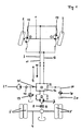
- Fig. 5 shows a schematic representation of a motor vehicle according to the invention, each with two rear axles 4 and two front axles 1.
- the rear of the two front axles 1 is connected to the two rear axles 4 via a drive shaft 30.
- the steerable front wheels 2 and the wheels 5 of the two rear axles 4 each have ABS sensors 31.
- a hydraulic constant pump 7 of a hydraulic circuit 3 is shown, via which the hydraulic constant pump 7 communicates with the two steerable front wheels 2 of the front axles 1.
- an inventive pressure oil distributor 22 is arranged between the two steerable front wheels 2 of the rear front axle 1.
- the rear two axles 4 of the motor vehicle each have conventional mechanical locking differentials 32 known from the prior art.
- a longitudinal lock 33 is arranged, which regulates the distribution of the driving force between the two mechanical locking differentials 32.
- the embodiments shown in Fig. 5 are in relation to the number of axles 1, 4 of the motor vehicle and with respect to the arrangement meant by pressure oil distributors 22 in the sense of the invention and other mechanical locking differentials 32 by no means limiting. In addition to the representation of Figure 5, other axle and differential combinations are conceivable.
- FIG. 6 shows the hydraulic inlet 23 opening into the pressure oil distributor 22 with a hydraulic oil flow 6.
- the hydraulic oil flow 6 is split up into two hydraulic inlets 23.
- the slide 29 have the hydraulic feeds 23 in the sense of the same or different power generation on the Einzelradmotoren 13 to the required hydraulic oil quantities.
Landscapes
- Engineering & Computer Science (AREA)
- General Engineering & Computer Science (AREA)
- Mechanical Engineering (AREA)
- Chemical & Material Sciences (AREA)
- Combustion & Propulsion (AREA)
- Transportation (AREA)
- Arrangement And Driving Of Transmission Devices (AREA)
- Motor Power Transmission Devices (AREA)
Abstract
Description
- Die Erfindung bezieht sich auf ein Kraftfahrzeug, insbesondere Nutzfahrzeug, mit mindestens einer lenkbaren Vorderachse und mindestens einer Hinterachse, von denen mindestens eine Hinterachse über einen mechanischen Antriebsstrang antreibbar ist und mit einem, einen Steuerblock aufweisenden Hydraulikkreislauf, der zur Speisung von hydraulischen Einzelradmotoren vorgesehen ist. Die Einzelradmotoren sind an wenigstens zwei lenkbaren Vorderrädern mindestens einer der Vorderachsen angeordnet und dienen zu deren Antrieb.
- Aus der
DE 199 61 960 A1 ist eine Antriebseinrichtung für Kraftfahrzeuge, insbesondere für Nutzfahrzeuge bekannt, die eine mechanische Antriebsverbindung zwischen einem Fahrzeugmotor und den Fahrzeugrädern einer der Fahrzeugachsen aufweist. Die Antriebseinrichtung weist darüber hinaus einen zu- und abschaltbaren Zusatzantrieb für die Fahrzeugräder wenigstens einer anderen Fahrzeugachse auf, der als hydrostatischer Einzelradantrieb ausgebildet ist und bei dem den Antriebsrädern jeweils als Zusatzantriebsmotor ein Hydromotor zugeordnet ist. Der Hydromotor ist mit wenigstens einer, vom Fahrzeugmotor angetriebenen Hydropumpe treibbar verbunden, wobei eine unabhängig von der Hydropumpe vom Fahrzeugmotor oder einem anderem fahrzeuginternen Energieträger antreibbare Speisepumpe vorgesehen ist. Der hydrostatische Einzelradantrieb, auf den sich die Druckschrift bezieht, hat die Eigenschaft, dass der Hydraulikkreislauf die Antriebsleistung im schlechtesten Fall auf das jenige hydrostatisch angetriebene Rad lenkt, das die geringste Bodenhaftung aufweist. Wünschenswert wäre deshalb, die Antriebseinrichtung dergestalt weiterzuentwickeln, dass der Antrieb über die hydrostatisch angetriebenen Einzelräder auch bei teilweisem oder vollständigem Traktionsverlust eines der Einzelräder erhalten bleibt. - Es ist daher die Aufgabe der Erfindung, ein Kraftfahrzeug zu schaffen, bei dem die Antriebskraft auch bei teilweisem oder völligem Verlust der Traktion eines der hydrostatisch angetriebenen Einzelräder aufrechtzuerhalten ist.
- Diese Aufgabe wird erfindungsgemäß dadurch gelöst, dass in dem Hydraulikkreislauf für die wenigstens zwei lenkbaren Vorderräder der Vorderachsen ein als Sperrdifferential wirkender, durch den Steuerblock geregelter Druckölverteiler angeordnet ist.
- Das der Erfindung zugrunde liegende Kraftfahrzeug, insbesondere Nutzfahrzeug weist zwei oder mehr Achsen auf, von denen wenigstens eine hintere Achse mit einem mechanischen Antriebsstrang angetrieben ist. Von den wenigstens zwei Achsen des Kraftfahrzeugs sind die Räder wenigstens einer Achse lenkbar. Im Weiteren wird beispielhaft von einem zweiachsigen Nutzfahrzeug ausgegangen, dessen hintere Achse durch den mechanischen Antriebstrang angetrieben wird und dessen vordere Achse lenkbar ist. Es ist vorstellbar, dass ein solches Nutzfahrzeug überwiegend auf festem Untergrund z. B. einer Straße mit ausreichender Traktion bewegt wird. Wird nun das Nutzfahrzeug z. B. abseits einer befestigten Straße auf einem Untergrund mit unzureichender Traktion bewegt, oder ist der Untergrund z. B. mit Schnee oder Eis bedeckt, hat der Kraftfahrzeug-Lenker die Möglichkeit, zusätzlich zu der im Normalzustand angetriebenen hinteren Achse über einen hydrostatischen Einzelradantrieb auch die lenkbaren Räder des Kraftfahrzeugs mit eigenem Antrieb zu versehen. Tritt der Fall auf, dass bei zugeschaltetem hydrostatischem Einzelradantrieb der lenkbaren Vorderräder eines der Vorderräder die Traktion gegenüber dem Untergrund ganz oder teilweise verliert, zeichnet sich der aus dem Stand der Technik bekannte hydrostatische Einzelradantrieb dadurch aus, dass die hydrostatische Antriebsleistung in dem Maß und Umfang, wie das eine der beiden hydrostatisch angetriebenen Einzelräder an Traktion einbüßt, auf das Rad mit der eingeschränkten Traktion übergeht. Die Erfindung bietet nun den Vorteil, dass durch einen im Hydraulikkreislauf angeordneten Steuerblock ein ebenfalls im Hydraulikkreislauf angeordneter Druckölverteiler die Hydraulikölmenge automatisch und/oder manuell wählbar, so auf die hydrostatisch angetriebenen Vorderräder verteilt, dass auch das über ausreichend Traktion verfügende hydrostatisch angetriebene Einzelrad ausreichende Antriebsleistung erhält, so dass die Fahrt des Nutzfahrzeugs fortgesetzt werden kann. Denkbar ist jedoch auch, die Antriebskraft über die Aufteilung der Ölmenge in jedem anderen Verhältnis auf die hydraulisch angetriebenen Einzelradmotoren zu verteilen. Vorstellbar ist, dass die die hydraulischen Einzelradmotoren parallele Konstanthydroölmotoren sind, die in den Radnaben der gelenkten Vorderachsen integriert sind. Eine radgetriebene Konstantölpumpe kann dabei über eine mechanische Übersetzung fest mit der Hinterachse verbunden sein. Sowohl die mechanische als auch die hydraulische Gesamtübersetzung ist so ausgelegt, dass zwischen den Vorder- und Hinterachsen Gleichlauf besteht. Dabei ist denkbar, dass die Hinterachse konventionell über Motor, Getriebe, Gelenkwelle und ein Hinterachsdifferential angetrieben ist. Mit Antrieb der Hinterräder erzeug die Konstantölpumpe einen hydraulischen Förderstrom im Hydraulikkreislauf, der den hydraulisch angetriebenen Einzelradmotoren zugeleitet wird. Zum Schutz vor Überdrehzahlen kann der Antrieb der Konstantölpumpe z. B. über eine Lamellen-Lastschaltkupplung geschaltet werden. Vorteilhaft ist, dass die Verteilung der Antriebskraft über den Hydraulikkreislauf im gleichmäßigen Teilungsverhältnis 50: 50 auf die hydraulischen Einzelradmotoren erfolgen kann, so dass der Druckölverteiler die funktionale Wirkung einer Differentialsperre hat. Es liegt jedoch kein mechanisches Sperrdifferential im herkömmlichen Sinne vor. Die Aufteilung der Antriebsleistung auf die hydraulischen Einzelradmotoren ist dabei druck- und viskositätsunabhängig. Vorteilhaft ist, dass für den Hydraulikkreislauf zum Abbau von Druckspitzen und zum Schutz gegenüber Leckagen Hochdruckschläuche Verwendung finden können. Ein weiterer Vorteil liegt darin, dass der Lenkeinschlag des erfindungsgemäßen Kraftfahrzeugs gegenüber einem herkömmlichen Kraftfahrzeug aus dem Stand der Technik nicht beeinträchtigt ist. Das erfindungsgemäße Kraftfahrzeug kann gleichermaßen mit einer oder mehreren Starrachsen oder mit Einzelradaufhängung ausgerüstet sein.
- In einer anderen Ausführungsform der Erfindung umfasst der Hydraulikkreislauf einen Hydraulikzu- und einen Hydraulikrücklauf, die den Druckölverteiler mit den Einzelmotoren verbinden.
- Nach einer weiteren Ausführungsform der Erfindung ist lediglich der Hydraulikzulauf mit dem Druckölverteiler verbunden, während der Hydraulikrücklauf unter Umgehung des Druckölverteilers unmittelbar mit dem Steuerblock verbunden ist.
- In einer anderen Ausführungsform der Erfindung ist lediglich der Hydraulikrücklauf mit dem Druckölverteiler verbunden, während der Hydraulikzulauf unter Umgehung des Druckölverteilers unmittelbar mit dem Steuerblock verbunden ist. Hierdurch wird der Einsatz eines konstruktionsmäßig einfacheren und dadurch kostengünstigeren Druckölverteilers möglich.
- In einer anderen Ausführungsform der Erfindung wirkt der Druckölverteiler in Bezug auf den Hydraulikkreislauf in Vorwärtsfahrt als Mengenteiler.
- In einer weiteren Ausführungsform der Erfindung wirkt der Druckölverteiler in Bezug auf den Hydraulikkreislauf in Rückwärtsfahrt als Summenteiler. Die hydrostatischen Einzelradmotoren funktionieren somit in beiden Fahrtrichtungen. Dabei wird die Ölflussrichtung im geschlossenen Hydraulikkreislauf von der Fahrtrichtung der Hinterachse bestimmt. Die Konstantölpumpe und die hydraulischen Einzelradmotoren sind doppelt wirkend als Saug-Druck-Aggregate ausgelegt.
- Eine weitere Ausführungsform der Erfindung zeigt, dass der eingangs zugeführte Hydraulikölstrom auf die beiden angeschlossenen Einzelradmotoren im Sinne gleicher und verschiedener Hydraulikölmengen aufteilbar ist.
- Eine weitere Ausführungsform der Erfindung ist dadurch gekennzeichnet, dass der Hydraulikkreislauf ein Hochdruckkreislauf ist. Die Verteilung der unter hohem Druck stehenden Ölmenge durch den Druckölverteiler auf die wenigstens zwei lenkbaren Vorderräder gewährleistet je nach Erfordernis eine gleiche oder unterschiedliche Verteilung der Antriebskraft auf die hydraulisch angetriebenen lenkbaren Vorderräder.
- Eine weitere Ausführungsform der Erfindung sieht vor, dass im Hydraulikkreislauf ein Anschluss für einen Speisekreislauf vorgesehen ist. Der Anschluss kann je nach Erfordernis in eine Hydraulikleitung erfolgen und/oder z. B. in den Steuerblock oder den Druckölverteiler einmünden. Der Speisekreislauf gewährleistet eine Befüllung oder Entleerung des Hydraulikkreislaufes z. B. im Wartungsfall.
- Nach einer weiteren Ausführungsform der Erfindung ist der Speisekreislauf ein Niederdruckkreislauf. Vorstellbar ist dabei, dass der Hydraulikkreislauf als Hochdruckkreislauf von einer motorgetriebenen Speisepumpe über einen Speisekreislauf versorgt wird. Dem Hydraulikkreislauf kann über ein Ausspeiseventil Öl entnommen werden, das über eine Ölkühlung zu einem Ölvorratsbehälter geleitet wird. Im Speisekreislauf kann ein Vorlauffilter, z. B. ein Druckfilter angeordnet sein. Im Speisekreislauf können Nachspeiseventile für den Ausgleich von Füllungsmängeln oder zur Kavitationsvermeidung bei Kurvenfahrt angeordnet sein.
- Nach einer anderen Ausführungsform der Erfindung weist der Druckölverteiler eine integrierte Freilaufsperrenschaltung auf.
- Nach einer weiteren Ausführungsform der Erfindung ist der Druckölverteiler zu- und abschaltbar.
- Vorstellbar ist, dass der Druckölverteiler in Abhängigkeit einer vorbestimmten Fahrgeschwindigkeit abschaltbar ist. Denkbar ist, dass die Zu- und Abschaltung des Druckölverteilers vom Kraftfahrzeug-Lenker über einen Ein/Aus-Schalter erfolgt und zusätzlich über ein CAN-fähiges elektronisches Steuergerät steuerbar ist. Die elektronische Steuerung gibt dabei das Zu- und Abschalten des Druckölverteilers aufgrund eines einprogrammierten Schaltprogrammes frei. Vorteilhaft ist darüber hinaus, dass Eingangssignale wie die Motordrehzahl, die Fahrgeschwindigkeit, die Raddrehzahlen von Vorder- und Hinterachsen, der Speisedruck, die Öltemperatur und z. B. das ABS-System bei der Regelung des Druckölverteilers durch den Steuerblock berücksichtigt werden können. Denkbar ist auch, dass der Steuerblock den Speisekreislauf zu- und abschaltet. Zum Schutz vor Überdrehung ist der Konstantölpumpe z. B. eine Lamellen-Lastschaltkupplung vorgeschaltet. Vorstellbar ist, dass der Steuerblock bei Überschreiten von vorbestimmten Parametern wie z. B. der Fahrgeschwindigkeit, der Öltemperatur, dem Ausfall von Speisedruck, vorliegender Unplausibilität der Raddrehzahlen von Vorderachse/n und Hinterachse/n oder bei Aktivierung des Anti-Blockier-Systems zugeschaltet werden kann.
- Nach einer weiteren Ausführungsform der Erfindung ist im Hydraulikkreislauf ein Rückschlagventil angeordnet.
- Weitere vorteilhafte Ausgestaltungen und zweckmäßige Fortbildungen des erfindungsgemäßen Kraftfahrzeugs sind aus den nachstehenden Beispielsbeschreibungen anhand der Zeichnung näher entnehmbar. Hierbei zeigen:
- Fig. 1
- in schematischer Darstellung ein Kraftfahrzeug nach dem Stand der Technik mit hydraulisch angetriebenen Einzelradmotoren,
- Fig. 2
- in schematischer Darstellung ein Kraftfahrzeug mit hydraulisch angetriebenen Einzelradmotoren und einem Druckölverteiler,
- Fig. 3
- ein Kraftfahrzeug entsprechend der Fig. 2 mit einem Hydraulikrücklauf und unter Umgehung des Druckölverteilers,
- Fig. 4
- ein Kraftfahrzeug entsprechend der Fig. 2 mit einem Hydraulikzulauf unter Umgehung des Druckölverteilers,
- Fig. 5
- in schematischer Darstellung ein vierachsiges Fahrzeug mit unterschiedlichen Differentialsperren in verschiedenen Anordnungen und
- Fig. 6
- in schematischer Darstellung ein Beispiel eines Druckölverteilers.
- Fig. 1 zeigt in schematischer Darstellung eine vordere Achse 1 mit hydraulisch angetriebenen lenkbaren Vorderrädern 2 und einem Hydraulikkreislauf 3. Mit Bezugsziffer 4 ist eine hintere Achse bezeichnet, an der die Hinterräder 5 angeordnet sind. Der Hydraulikkreislauf 3 weist eine Hydrokonstantpumpe 7 auf, die im Beispiel der Figur 1 radgetrieben ist und über eine feste mechanische Übersetzung mit den Rädern 5 der hinteren Achse 4 verbunden ist. Zwischen der hinteren Achse 4 und der Hydrokonstantpumpe 7 ist eine Kupplung 8, bspw. eine Lamellen-Lastschaltkupplung vorgesehen. Der Hydraulikkreislauf 3 ist als geschlossener Kreislauf dargestellt, wobei die Hydrokonstantpumpe 7 in Abhängigkeit von der Vorgabe der hinteren Achse 4 in Vorwärtsrichtung 9 oder in Rückwärtsrichtung 10 angetrieben werden kann. Wird die Hydrokonstantpumpe 7 in Vorwärtsrichtung 9 angetrieben, durchströmt das Hydrauliköl den Ast 11 des Hydraulikkreislaufes 3 in Vorwärtsrichtung 9, wodurch die jeweils an den lenkbaren Vorderrädern 2 angeordneten hydraulischen Einzeiradmotoren 13 in Vorwärtsrichtung 9 angetrieben werden. Der Rücklauf des Hydrauliköls erfolgt in diesem Fall über den Ast 12 des Hydraulikkreislaufes 3. Aufgrund der Tatsache, dass die Hydrokonstantpumpe 7 in Vorwärtsrichtung 9 sowie in Rückwärtsrichtung 10 betrieben werden kann, folgt, dass die beiden Äste 11, 12 des Hydraulikkreislaufes 3 wechselseitig in beiden Fahrtrichtungen 9; 10 befahren werden können. Im Hydraulikkreislauf 3 ist ein Steuerblock 14 angeordnet, der einen Anschluss 15 eines Speisekreislaufes 16 aufweist. In der Figur 1 ist dargestellt, dass im Speisekreislauf 16 ein Vorlauffilter 17, ein Ölkühler 18 und ein Speisedruckregler 19 angeordnet sind. Der Speiseölkreislauf 16 weist zusätzlich einen ÖlVorratsbehälter 20 sowie eine Speisepumpe 21 auf. Der Hydraulikkreislauf 3 ist als geschlossener Hochdruckkreislauf dargestellt, wogegen der Speisekreislauf 16 gestrichelt als offener Niederdruckkreislauf gezeigt ist.
- Die Fig. 2 weist gegenüber der vorhergehenden Fig. 1 den Unterschied auf, dass im Hydraulikkreislauf 3 zwischen dem Steuerblock 14 und den hydraulischen Einzelradmotoren 13 ein Druckölverteiler 22 angeordnet ist. Der Druckölverteiler 22 ist mit dem Steuerblock 14 durch je einen Ast 11; 12 verbunden und steht mit jedem hydraulischen Einzelradmotor 13 über je einen Hydraulikzulauf 23 und einen Hydraulikrücklauf 24 in Verbindung. In Abhängigkeit davon, ob die hintere Achse 4 in Vorwärtsrichtung 9 oder in Rückwärtsrichtung 10 angetrieben wird, durchströmt das Hydrauliköl die Äste 11; 12 bzw. den Hydraulikzulauf 23 bzw. den Hydraulikrücklauf 24 entsprechend in Vorwärtsrichtung 9 oder in Rückwärtsrichtung 10. Im Beispiel der Fig. 2 weist der Druckölverteiler 22 im Hydraulikkreislauf 3 steuerblockseitig mit den Ästen 11; 12 je einen Zu- und einen Ablauf für das Hydrauliköl auf. Vorderachsseitig verfügt der Druckölverteiler 22 je hydraulischem Einzelradmotor 13 über einen Hydraulikzulauf 23 und einen Hydraulikrücklauf 24. Der Druckölverteiler ist an den Speisekreislauf 16 angeschlossen und weist einen weiteren Öl-Vorratsbehälter 25 auf. Die Pfeile 26 bzw. 27 zeigen die Hydraulikölflussrichtung in Vorwärtsrichtung 9. Die Strömungsrichtung (entsprechend den Pfeilen 26 bzw. 27) des Hydrauliköls verläuft bei Rückwärtsrichtung 10 jeweils in entgegengesetzter Richtung. Mit Bezugsziffer 28 ist ein Regler zur Zu- und Abschaltung des Hydraulikkreislaufes 3 und des Speisekreislaufes 16 dargestellt.
- Fig. 3 unterscheidet sich von der Darstellung in Fig. 2 dergestalt, dass der Hydraulikrücklauf 24 der beiden Hydraulikeinzelradmotoren 13 zum Steuerblock 14 unter Umgehung des Druckölverteilers 22 direkt zum Steuerblock 14 verläuft. Die Fig. 3 zeigt die Funktionsweise des Druckölverteilers 22 in Vorwärtsrichtung 9. Das Hydrauliköl durchströmt den Hydraulikkreislauf 3 entsprechend der Pfeile 26; 27. Der Druckölverteiler 22 wirkt dabei im Bezug auf das Hydrauliköl als Mengenteiler.
- Fig. 4 zeigt die in der Fig. 3 dargestellte Ausführungsform der Erfindung mit dem Unterschied, dass der Druckölverteiler 22 in Rückwärtsrichtung 10 betrieben wird. Hierbei verläuft der Hydraulikzulauf 23 zwischen dem Steuerblock 14 und den hydraulischen Einzelradmotoren 13 unmittelbar unter Umgehung des Druckölverteilers 22. Die Strömungsrichtung des Hydrauliköls im Hydraulikkreislauf 3 wird durch die Pfeile 26; 27 dargestellt. Der Druckölverteiler 22 wirkt in Fig. 4 in Bezug auf das Hydrauliköl als Summenteiler.
- Fig. 5 zeigt in schematischer Darstellung ein Kraftfahrzeug nach Maßgabe der Erfindung mit je zwei hinteren Achsen 4 sowie zwei vorderen Achsen 1. Die hintere der beiden vorderen Achsen 1 ist mit den beiden hinteren Achsen 4 über eine Antriebswelle 30 verbunden. Die lenkbaren Vorderräder 2 sowie die Räder 5 der beiden hinteren Achsen 4 weisen jeweils ABS-Sensoren 31 auf. Zwischen den hinteren Achsen 4 und den beiden dargestellten vorderen Achsen 1 ist eine Hydrokonstantpumpe 7 eines Hydraulikkreislaufes 3 dargestellt, über den die Hydrokonstantpumpe 7 mit den beiden lenkbaren Vorderrädern 2 der Vorderachsen 1 in Verbindung steht. Zwischen den beiden lenkbaren Vorderrädern 2 der hinteren Vorderachse 1 ist ein erfindungsgemäßer Druckölverteiler 22 angeordnet. Die hinteren beiden Achsen 4 des Kraftfahrzeugs weisen jeweils herkömmliche, aus dem Stand der Technik bekannte mechanische Sperrdifferentiale 32 auf. Zwischen den beiden hinteren Achsen 4 ist eine Längssperre 33 angeordnet, die die Verteilung der Antriebskraft zwischen deren beiden mechanischen Sperrdifferentialen 32 regelt. Die in der Fig. 5 dargestellte Ausführungsformen sind in Bezug auf die Anzahl der Achsen 1;4 des Kraftfahrzeugs sowie in Bezug auf die Anordnung von Druckölverteilern 22 im Sinn der Erfindung sowie sonstigen mechanischen Sperrdifferentialen 32 keineswegs begrenzend gemeint. Neben der Darstellung der Figur 5 sind auch andere Achs- und Differentialkombinationen denkbar.
- Fig. 6 zeigt den in den Druckölverteiler 22 einmündenden Hydraulikzulauf 23 mit einem Hydraulikölstrom 6. Im Druckölverteiler 22 wird der Hydraulikölstrom 6 auf zwei Hydraulikzuläufe 23 aufgeteilt. Die Schieber 29 weisen den Hydraulikzuläufen 23 im Sinne gleicher oder unterschiedlicher Leistungserzeugung an den Einzelradmotoren 13 die erforderlichen Hydraulikölmengen zu.
-
- 1
- Vordere Achse
- 2
- Lenkbare Vorderräder
- 3
- Hydraulikkreislauf
- 4
- Hintere Achse
- 5
- Hinterräder
- 6
- 7
- Hydrokonstantpumpe
- 8
- Kupplung
- 9
- Vorwärtsrichtung
- 10
- Rückwärtsrichtung
- 11
- Ast
- 12
- Ast
- 13
- Hydraulischer Einzelradmotor
- 14
- Steuerblock
- 15
- Anschluss des Speisekreislaufs
- 16
- Speisekreislauf
- 17
- Vorlauffilter
- 18
- Ölkühler
- 19
- Speisedruckregler
- 20
- Öl-Vorratsbehälter
- 21
- Speisepumpe
- 22
- Druckölverteiler
- 23
- Hydraulikzulauf
- 24
- Hydraulikrücklauf
- 25
- Weiterer Öl-Vorratsbehälter
- 26
- Pfeil - Vorwärtsrichtung
- 27
- Pfeil - Rückwärtsrichtung
- 28
- Regler
- 29
- Gemeinsame Hydraulikleitung
- 30
- Antriebswelle
- 31
- ABS-Sensor
- 32
- Mechanisches Sperrdifferential
- 33
- Längssperre
Claims (14)
- Kraftfahrzeug, insbesondere Nutzfahrzeug, mit mindestens einer lenkbaren Vorderachse und mindestens einer Hinterachse, von denen mindestens eine Hinterachse über einen mechanischen Antriebsstrang antreibbar ist und mit einem, einen Steuerblock aufweisenden Hydraulikkreislauf, der zur Speisung von hydraulischen Einzelradmotoren vorgesehen ist, die an wenigstens zwei lenkbaren Vorderrädern mindestens einer der Vorderachsen angeordnet sind und zu deren Antrieb dienen, dadurch gekennzeichnet, dass in dem Hydraulikkreislauf (3) für die wenigstens zwei lenkbaren Vorderräder (2) der Vorderachsen (1) ein als Sperrdifferential wirkender, durch den Steuerblock (14) geregelter Druckölverteiler (22) angeordnet ist.
- Kraftfahrzeug nach Anspruch 1, dadurch gekennzeichnet, dass der Hydraulikkreislauf (3) einen Hydraulikzu- und einen Rücklauf (23, 24) umfasst, der den Druckölverteiler (22) mit den Einzelmotoren verbindet.
- Kraftfahrzeug nach Anspruch 2, dadurch gekennzeichnet, dass lediglich der Hydraulikzulauf (23) mit dem Druckölverteiler (22) verbunden ist, während der Hydraulikrücklauf (24) unter Umgehung des Druckölverteilers (22) unmittelbar mit dem Steuerblock (14) verbunden ist.
- Kraftfahrzeug nach Anspruch 2, dadurch gekennzeichnet, dass lediglich der Hydraulikrücklauf (24) mit dem Druckölverteiler (22) verbunden ist, während der Hydraulikzulauf (23) unter Umgehung des Druckölverteilers (22) unmittelbar mit dem Steuerblock (14) verbunden ist.
- Kraftfahrzeug nach Anspruch 1, dadurch gekennzeichnet, dass der Druckölverteiler (22) in Bezug auf den Hydraulikkreislauf (3) in Vorwärtsfahrt (9) als Mengenteiler wirkt.
- Kraftfahrzeug nach Anspruch 1, dadurch gekennzeichnet, dass der Druckölverteiler (22) in Bezug auf den Hydraulikkreislauf (3) in Rückwärtsfahrt (10) als Summenteiler wirkt.
- Kraftfahrzeug nach Anspruch 1, dadurch gekennzeichnet, dass der eingangs zugeführte Hydraulikölstrom auf die beiden angeschlossenen Einzelradmotoren im Sinne gleicher und verschiedener Hydraulikölmengen aufteilbar ist.
- Kraftfahrzeug nach Anspruch 1, dadurch gekennzeichnet, dass der Hydraulikkreislauf (3) ein Hochdruckkreislauf ist.
- Kraftfahrzeug nach Anspruch 1, dadurch gekennzeichnet, dass im Hydraulikkreislauf (3) ein Anschluss für einen Speisekreislauf (16) vorgesehen ist.
- Kraftfahrzeug nach Anspruch 8, dadurch gekennzeichnet, dass der Speisekreislauf (16) ein Niederdruckkreislauf ist.
- Kraftfahrzeug nach Anspruch 1, dadurch gekennzeichnet, dass der Druckölverteiler (22) eine integrierte Freilaufsperrenschaltung aufweist.
- Kraftfahrzeug nach Anspruch 1, dadurch gekennzeichnet, dass der Druckölverteiler (22) zu- und abschaltbar ist.
- Kraftfahrzeug nach Anspruch 1, dadurch gekennzeichnet, dass der Druckölverteiler (22) in Abhängigkeit einer vorbestimmten Fahrgeschwindigkeit abschaltbar ist.
- Kraftfahrzeug nach Anspruch 1, dadurch gekennzeichnet, dass im Hydraulikkreislauf (3) ein Rückschlagventil angeordnet ist.
Applications Claiming Priority (1)
| Application Number | Priority Date | Filing Date | Title |
|---|---|---|---|
| AT0135006A AT503973B1 (de) | 2006-08-11 | 2006-08-11 | Quersperre für ''man-hydrodrive'' |
Publications (4)
| Publication Number | Publication Date |
|---|---|
| EP1886861A2 true EP1886861A2 (de) | 2008-02-13 |
| EP1886861A3 EP1886861A3 (de) | 2009-10-21 |
| EP1886861B1 EP1886861B1 (de) | 2011-10-26 |
| EP1886861B2 EP1886861B2 (de) | 2020-10-07 |
Family
ID=38658142
Family Applications (1)
| Application Number | Title | Priority Date | Filing Date |
|---|---|---|---|
| EP07015157.6A Active EP1886861B2 (de) | 2006-08-11 | 2007-08-02 | Quersperre für MAN-Hydrodrive |
Country Status (2)
| Country | Link |
|---|---|
| EP (1) | EP1886861B2 (de) |
| AT (2) | AT503973B1 (de) |
Cited By (12)
| Publication number | Priority date | Publication date | Assignee | Title |
|---|---|---|---|---|
| WO2012163375A1 (en) | 2011-06-01 | 2012-12-06 | Volvo Lastvagnar Ab | Load carrying truck provided with a traction system and a method for the control of a traction system of a load carrying truck |
| EP2559581A2 (de) | 2011-08-18 | 2013-02-20 | MAN Truck & Bus AG | Antriebssystem für ein Kraftfahrzeug mit einem als Sperrdifferential wirkenden Bremssystem |
| WO2013167145A1 (en) | 2012-05-07 | 2013-11-14 | Volvo Lastvagnar Ab | A heavy road vehicle comprising an additional traction system |
| WO2013167148A1 (en) | 2012-05-08 | 2013-11-14 | Volvo Lastvagnar Ab | Traction system and a method for controlling said traction system |
| EP2832574A1 (de) * | 2013-08-03 | 2015-02-04 | MAN Truck & Bus AG | Hydrauliksystem mit Schutzfunktion |
| EP2832573A1 (de) * | 2013-08-03 | 2015-02-04 | MAN Truck & Bus AG | Hydrauliksystem mit Drehzahlabsicherung einer Pumpe |
| DE102015014213A1 (de) | 2015-11-04 | 2017-05-04 | Man Truck & Bus Ag | Nutzfahrzeug, insbesondere LKW, mit mindestens einem Doppelachsaggregat |
| EP3620318A1 (de) | 2018-09-06 | 2020-03-11 | MAN Truck & Bus SE | Hydraulische drosselvorrichtung |
| EP3628524A1 (de) | 2018-09-28 | 2020-04-01 | MAN Truck & Bus SE | Antriebssystem mit variabler sperrdifferential-funktion |
| EP3628895A1 (de) | 2018-09-28 | 2020-04-01 | MAN Truck & Bus SE | Hydrostatischer antrieb für ein kraftfahrzeug |
| EP3628525A1 (de) | 2018-09-28 | 2020-04-01 | MAN Truck & Bus SE | Kraftfahrzeug mit einem hilfsantrieb für eine lenkbare achse |
| EP4086098A1 (de) | 2021-05-03 | 2022-11-09 | Geurts Investment | Selbstfahrendes fahrzeug und verfahren zum überqueren von land in einem breiten geschwindigkeitsbereich |
Citations (2)
| Publication number | Priority date | Publication date | Assignee | Title |
|---|---|---|---|---|
| US4140196A (en) | 1977-06-07 | 1979-02-20 | Parno Corporation | Auxiliary drive system |
| DE19961960A1 (de) | 1999-12-22 | 2001-09-27 | Man Nutzfahrzeuge Ag | Antriebseinrichtung für Kraftfahrzeuge |
Family Cites Families (6)
| Publication number | Priority date | Publication date | Assignee | Title |
|---|---|---|---|---|
| US3864910A (en) * | 1972-05-24 | 1975-02-11 | Poclain Sa | Device for supplying fluid under pressure to two reversible load elements |
| DE2326857C2 (de) * | 1973-05-25 | 1974-10-03 | Hydromatik Gmbh, 7900 Ulm | Hydrostatisches Getriebe mit zwei oder mehreren von einer gemeinsamen Stellpumpe parallel getriebenen Hydromotoren |
| US3918546A (en) * | 1973-11-21 | 1975-11-11 | Clark Equipment Co | Hydrostatic assist drive for vehicles |
| US3997017A (en) † | 1974-01-14 | 1976-12-14 | Caterpillar Tractor Co. | Auxiliary hydrostatic front wheel drive system |
| US4236595A (en) * | 1979-08-17 | 1980-12-02 | Parno Corp. | Auxiliary drive system |
| FR2859671B1 (fr) † | 2003-09-16 | 2007-11-09 | Fam Automobiles | Dispositif hydraulique additionnel et temporaire pour vehicule routier leger permettant l'entrainement d'une ou plusieurs roues pour la/les rendre(nt) motrice(s) en plus de la transmission d'origine |
-
2006
- 2006-08-11 AT AT0135006A patent/AT503973B1/de active
-
2007
- 2007-08-02 AT AT07015157T patent/ATE530371T1/de active
- 2007-08-02 EP EP07015157.6A patent/EP1886861B2/de active Active
Patent Citations (2)
| Publication number | Priority date | Publication date | Assignee | Title |
|---|---|---|---|---|
| US4140196A (en) | 1977-06-07 | 1979-02-20 | Parno Corporation | Auxiliary drive system |
| DE19961960A1 (de) | 1999-12-22 | 2001-09-27 | Man Nutzfahrzeuge Ag | Antriebseinrichtung für Kraftfahrzeuge |
Cited By (19)
| Publication number | Priority date | Publication date | Assignee | Title |
|---|---|---|---|---|
| WO2012163375A1 (en) | 2011-06-01 | 2012-12-06 | Volvo Lastvagnar Ab | Load carrying truck provided with a traction system and a method for the control of a traction system of a load carrying truck |
| EP2559581A2 (de) | 2011-08-18 | 2013-02-20 | MAN Truck & Bus AG | Antriebssystem für ein Kraftfahrzeug mit einem als Sperrdifferential wirkenden Bremssystem |
| DE102011111003A1 (de) | 2011-08-18 | 2013-02-21 | Man Truck & Bus Ag | Antriebssystem für ein Kraftfahrzeug mit einem als Sperrdifferential wirkenden Bremssystem |
| EP2559581A3 (de) * | 2011-08-18 | 2013-12-11 | MAN Truck & Bus AG | Antriebssystem für ein Kraftfahrzeug mit einem als Sperrdifferential wirkenden Bremssystem |
| WO2013167145A1 (en) | 2012-05-07 | 2013-11-14 | Volvo Lastvagnar Ab | A heavy road vehicle comprising an additional traction system |
| WO2013167148A1 (en) | 2012-05-08 | 2013-11-14 | Volvo Lastvagnar Ab | Traction system and a method for controlling said traction system |
| EP2832574A1 (de) * | 2013-08-03 | 2015-02-04 | MAN Truck & Bus AG | Hydrauliksystem mit Schutzfunktion |
| EP2832573A1 (de) * | 2013-08-03 | 2015-02-04 | MAN Truck & Bus AG | Hydrauliksystem mit Drehzahlabsicherung einer Pumpe |
| DE102015014213A1 (de) | 2015-11-04 | 2017-05-04 | Man Truck & Bus Ag | Nutzfahrzeug, insbesondere LKW, mit mindestens einem Doppelachsaggregat |
| EP3165395A1 (de) | 2015-11-04 | 2017-05-10 | MAN Truck & Bus AG | Nutzfahrzeug, insbesondere lkw, mit mindestens einem doppelachsaggregat |
| EP3165395B1 (de) | 2015-11-04 | 2019-02-27 | MAN Truck & Bus AG | Nutzfahrzeug, insbesondere lkw, mit mindestens einem doppelachsaggregat |
| EP3620318A1 (de) | 2018-09-06 | 2020-03-11 | MAN Truck & Bus SE | Hydraulische drosselvorrichtung |
| EP3628524A1 (de) | 2018-09-28 | 2020-04-01 | MAN Truck & Bus SE | Antriebssystem mit variabler sperrdifferential-funktion |
| EP3628895A1 (de) | 2018-09-28 | 2020-04-01 | MAN Truck & Bus SE | Hydrostatischer antrieb für ein kraftfahrzeug |
| EP3628525A1 (de) | 2018-09-28 | 2020-04-01 | MAN Truck & Bus SE | Kraftfahrzeug mit einem hilfsantrieb für eine lenkbare achse |
| DE102018124020A1 (de) * | 2018-09-28 | 2020-04-02 | Man Truck & Bus Se | Antriebssystem mit variabler Sperrdifferential-Funktion |
| DE102018124014A1 (de) * | 2018-09-28 | 2020-04-02 | Man Truck & Bus Se | Kraftfahrzeug mit einem Hilfsantrieb für eine lenkbare Achse |
| EP4086098A1 (de) | 2021-05-03 | 2022-11-09 | Geurts Investment | Selbstfahrendes fahrzeug und verfahren zum überqueren von land in einem breiten geschwindigkeitsbereich |
| NL2028129B1 (en) | 2021-05-03 | 2022-11-10 | Geurts Invest B V | A self-propelled vehicle and method for crossing land at a broad speed range |
Also Published As
| Publication number | Publication date |
|---|---|
| EP1886861B1 (de) | 2011-10-26 |
| ATE530371T1 (de) | 2011-11-15 |
| EP1886861A3 (de) | 2009-10-21 |
| AT503973A1 (de) | 2008-02-15 |
| EP1886861B2 (de) | 2020-10-07 |
| AT503973B1 (de) | 2008-06-15 |
Similar Documents
| Publication | Publication Date | Title |
|---|---|---|
| EP1886861B1 (de) | Quersperre für MAN-Hydrodrive | |
| EP0436716B1 (de) | Hydrostatischer antrieb für mehrachsig angetriebene fahrzeuge sowie verfahren zum hydrostatischen antreiben derartiger fahrzeuge und anderer baueinheiten | |
| DE112008000531B4 (de) | Hydrostatische Antriebsvorrichtung eines fahrbaren Geräts | |
| DE102007038701A1 (de) | Drehmomentverteilungssystem mit elektronisch gesteuertem Verteilergetriebemodul | |
| EP2562442B1 (de) | Schaltgetriebe, insbesondere für einen Antriebsstrang in Kraftfahrzeugen, Schienenfahrzeugen oder dergleichen | |
| EP1508494B1 (de) | Hilfskraftunterstütztes Lenksystem für ein Kraftfahrzeug, mit hydraulischer offener Mitte | |
| DE102014104549A1 (de) | Lenkbares Raupenfahrwerk | |
| EP2559581B1 (de) | Antriebssystem für ein Kraftfahrzeug mit einem als Sperrdifferential wirkenden Bremssystem | |
| DE10025508B4 (de) | Fahrzeug-Antriebsanordnung | |
| EP1185807B1 (de) | Hydrostatischer fahrantrieb | |
| CH689015A5 (de) | Verfahren zur Antriebssteuerung eines Einachstraktors. | |
| DE102006016006B4 (de) | Hydrostatischer Fahrantrieb | |
| DE10135862A1 (de) | Fahrzeuglenkung | |
| DE1455957A1 (de) | Motoranlage fuer Landfahrzeuge mit Waermekraftmaschine und hydrostatischer Kraftuebertragung | |
| DE2855573A1 (de) | Antrieb fuer landfahrzeuge | |
| DE2757237C3 (de) | ||
| DE69919958T2 (de) | Traktor mit Schmierungssystem | |
| DE102004009260A1 (de) | Verfahren zum Betrieb einer mit einem Antriebsmotor gekoppelten Wegzapfwelle | |
| DE10017901A1 (de) | Hydrostatischer Fahrantrieb | |
| EP3628895B1 (de) | Hydrostatischer antrieb für ein kraftfahrzeug | |
| DE102006014194B4 (de) | Hydrauliksystem zur Versorgung eines Aktuators in einem Kraftfahrzeug | |
| DE3636153C1 (de) | Gangwechsel- und Lenkgetriebe fuer ein Vollkettenfahrzeug | |
| DE202017004555U1 (de) | Leistungsverzweigungsgetriebe für eine mobile Arbeitsmaschine zur gleichzeitigen, geregelten Leistungsabgabe zum Antreiben des Fahrzeugs und der Nebenaggregate | |
| DE4015122C2 (de) | ||
| DE2931681A1 (de) | Lastkraftfahrzeug, insbesondere omnibus |
Legal Events
| Date | Code | Title | Description |
|---|---|---|---|
| PUAI | Public reference made under article 153(3) epc to a published international application that has entered the european phase |
Free format text: ORIGINAL CODE: 0009012 |
|
| AK | Designated contracting states |
Kind code of ref document: A2 Designated state(s): AT BE BG CH CY CZ DE DK EE ES FI FR GB GR HU IE IS IT LI LT LU LV MC MT NL PL PT RO SE SI SK TR |
|
| AX | Request for extension of the european patent |
Extension state: AL BA HR MK YU |
|
| PUAL | Search report despatched |
Free format text: ORIGINAL CODE: 0009013 |
|
| AK | Designated contracting states |
Kind code of ref document: A3 Designated state(s): AT BE BG CH CY CZ DE DK EE ES FI FR GB GR HU IE IS IT LI LT LU LV MC MT NL PL PT RO SE SI SK TR |
|
| AX | Request for extension of the european patent |
Extension state: AL BA HR MK RS |
|
| 17P | Request for examination filed |
Effective date: 20091125 |
|
| 17Q | First examination report despatched |
Effective date: 20091222 |
|
| AKX | Designation fees paid |
Designated state(s): AT BE BG CH CY CZ DE DK EE ES FI FR GB GR HU IE IS IT LI LT LU LV MC MT NL PL PT RO SE SI SK TR |
|
| GRAP | Despatch of communication of intention to grant a patent |
Free format text: ORIGINAL CODE: EPIDOSNIGR1 |
|
| GRAS | Grant fee paid |
Free format text: ORIGINAL CODE: EPIDOSNIGR3 |
|
| GRAA | (expected) grant |
Free format text: ORIGINAL CODE: 0009210 |
|
| AK | Designated contracting states |
Kind code of ref document: B1 Designated state(s): AT BE BG CH CY CZ DE DK EE ES FI FR GB GR HU IE IS IT LI LT LU LV MC MT NL PL PT RO SE SI SK TR |
|
| REG | Reference to a national code |
Ref country code: GB Ref legal event code: FG4D Free format text: NOT ENGLISH |
|
| REG | Reference to a national code |
Ref country code: CH Ref legal event code: EP |
|
| REG | Reference to a national code |
Ref country code: IE Ref legal event code: FG4D |
|
| REG | Reference to a national code |
Ref country code: DE Ref legal event code: R096 Ref document number: 502007008496 Country of ref document: DE Effective date: 20111229 |
|
| REG | Reference to a national code |
Ref country code: NL Ref legal event code: VDEP Effective date: 20111026 |
|
| REG | Reference to a national code |
Ref country code: SE Ref legal event code: TRGR |
|
| LTIE | Lt: invalidation of european patent or patent extension |
Effective date: 20111026 |
|
| PG25 | Lapsed in a contracting state [announced via postgrant information from national office to epo] |
Ref country code: IS Free format text: LAPSE BECAUSE OF FAILURE TO SUBMIT A TRANSLATION OF THE DESCRIPTION OR TO PAY THE FEE WITHIN THE PRESCRIBED TIME-LIMIT Effective date: 20120226 Ref country code: LT Free format text: LAPSE BECAUSE OF FAILURE TO SUBMIT A TRANSLATION OF THE DESCRIPTION OR TO PAY THE FEE WITHIN THE PRESCRIBED TIME-LIMIT Effective date: 20111026 |
|
| PG25 | Lapsed in a contracting state [announced via postgrant information from national office to epo] |
Ref country code: NL Free format text: LAPSE BECAUSE OF FAILURE TO SUBMIT A TRANSLATION OF THE DESCRIPTION OR TO PAY THE FEE WITHIN THE PRESCRIBED TIME-LIMIT Effective date: 20111026 Ref country code: GR Free format text: LAPSE BECAUSE OF FAILURE TO SUBMIT A TRANSLATION OF THE DESCRIPTION OR TO PAY THE FEE WITHIN THE PRESCRIBED TIME-LIMIT Effective date: 20120127 Ref country code: SI Free format text: LAPSE BECAUSE OF FAILURE TO SUBMIT A TRANSLATION OF THE DESCRIPTION OR TO PAY THE FEE WITHIN THE PRESCRIBED TIME-LIMIT Effective date: 20111026 Ref country code: PL Free format text: LAPSE BECAUSE OF FAILURE TO SUBMIT A TRANSLATION OF THE DESCRIPTION OR TO PAY THE FEE WITHIN THE PRESCRIBED TIME-LIMIT Effective date: 20111026 Ref country code: PT Free format text: LAPSE BECAUSE OF FAILURE TO SUBMIT A TRANSLATION OF THE DESCRIPTION OR TO PAY THE FEE WITHIN THE PRESCRIBED TIME-LIMIT Effective date: 20120227 Ref country code: LV Free format text: LAPSE BECAUSE OF FAILURE TO SUBMIT A TRANSLATION OF THE DESCRIPTION OR TO PAY THE FEE WITHIN THE PRESCRIBED TIME-LIMIT Effective date: 20111026 |
|
| REG | Reference to a national code |
Ref country code: IE Ref legal event code: FD4D |
|
| PG25 | Lapsed in a contracting state [announced via postgrant information from national office to epo] |
Ref country code: CY Free format text: LAPSE BECAUSE OF FAILURE TO SUBMIT A TRANSLATION OF THE DESCRIPTION OR TO PAY THE FEE WITHIN THE PRESCRIBED TIME-LIMIT Effective date: 20111026 |
|
| PG25 | Lapsed in a contracting state [announced via postgrant information from national office to epo] |
Ref country code: DK Free format text: LAPSE BECAUSE OF FAILURE TO SUBMIT A TRANSLATION OF THE DESCRIPTION OR TO PAY THE FEE WITHIN THE PRESCRIBED TIME-LIMIT Effective date: 20111026 Ref country code: BG Free format text: LAPSE BECAUSE OF FAILURE TO SUBMIT A TRANSLATION OF THE DESCRIPTION OR TO PAY THE FEE WITHIN THE PRESCRIBED TIME-LIMIT Effective date: 20120126 Ref country code: SK Free format text: LAPSE BECAUSE OF FAILURE TO SUBMIT A TRANSLATION OF THE DESCRIPTION OR TO PAY THE FEE WITHIN THE PRESCRIBED TIME-LIMIT Effective date: 20111026 Ref country code: IE Free format text: LAPSE BECAUSE OF FAILURE TO SUBMIT A TRANSLATION OF THE DESCRIPTION OR TO PAY THE FEE WITHIN THE PRESCRIBED TIME-LIMIT Effective date: 20111026 Ref country code: CZ Free format text: LAPSE BECAUSE OF FAILURE TO SUBMIT A TRANSLATION OF THE DESCRIPTION OR TO PAY THE FEE WITHIN THE PRESCRIBED TIME-LIMIT Effective date: 20111026 Ref country code: EE Free format text: LAPSE BECAUSE OF FAILURE TO SUBMIT A TRANSLATION OF THE DESCRIPTION OR TO PAY THE FEE WITHIN THE PRESCRIBED TIME-LIMIT Effective date: 20111026 |
|
| PLBI | Opposition filed |
Free format text: ORIGINAL CODE: 0009260 |
|
| PG25 | Lapsed in a contracting state [announced via postgrant information from national office to epo] |
Ref country code: RO Free format text: LAPSE BECAUSE OF FAILURE TO SUBMIT A TRANSLATION OF THE DESCRIPTION OR TO PAY THE FEE WITHIN THE PRESCRIBED TIME-LIMIT Effective date: 20111026 Ref country code: IT Free format text: LAPSE BECAUSE OF FAILURE TO SUBMIT A TRANSLATION OF THE DESCRIPTION OR TO PAY THE FEE WITHIN THE PRESCRIBED TIME-LIMIT Effective date: 20111026 |
|
| 26 | Opposition filed |
Opponent name: POCLAIN HYDRAULICS INDUSTRIE Effective date: 20120725 |
|
| PLAX | Notice of opposition and request to file observation + time limit sent |
Free format text: ORIGINAL CODE: EPIDOSNOBS2 |
|
| REG | Reference to a national code |
Ref country code: DE Ref legal event code: R026 Ref document number: 502007008496 Country of ref document: DE Effective date: 20120725 |
|
| PLAF | Information modified related to communication of a notice of opposition and request to file observations + time limit |
Free format text: ORIGINAL CODE: EPIDOSCOBS2 |
|
| BERE | Be: lapsed |
Owner name: MAN NUTZFAHRZEUGE OSTERREICH AG Effective date: 20120831 |
|
| PG25 | Lapsed in a contracting state [announced via postgrant information from national office to epo] |
Ref country code: MC Free format text: LAPSE BECAUSE OF NON-PAYMENT OF DUE FEES Effective date: 20120831 |
|
| GBPC | Gb: european patent ceased through non-payment of renewal fee |
Effective date: 20120802 |
|
| PLBB | Reply of patent proprietor to notice(s) of opposition received |
Free format text: ORIGINAL CODE: EPIDOSNOBS3 |
|
| PG25 | Lapsed in a contracting state [announced via postgrant information from national office to epo] |
Ref country code: ES Free format text: LAPSE BECAUSE OF FAILURE TO SUBMIT A TRANSLATION OF THE DESCRIPTION OR TO PAY THE FEE WITHIN THE PRESCRIBED TIME-LIMIT Effective date: 20120206 |
|
| RAP2 | Party data changed (patent owner data changed or rights of a patent transferred) |
Owner name: MAN TRUCK & BUS OESTERREICH AG |
|
| REG | Reference to a national code |
Ref country code: FR Ref legal event code: ST Effective date: 20130430 |
|
| PG25 | Lapsed in a contracting state [announced via postgrant information from national office to epo] |
Ref country code: BE Free format text: LAPSE BECAUSE OF NON-PAYMENT OF DUE FEES Effective date: 20120831 |
|
| PG25 | Lapsed in a contracting state [announced via postgrant information from national office to epo] |
Ref country code: FI Free format text: LAPSE BECAUSE OF FAILURE TO SUBMIT A TRANSLATION OF THE DESCRIPTION OR TO PAY THE FEE WITHIN THE PRESCRIBED TIME-LIMIT Effective date: 20111026 |
|
| PG25 | Lapsed in a contracting state [announced via postgrant information from national office to epo] |
Ref country code: GB Free format text: LAPSE BECAUSE OF NON-PAYMENT OF DUE FEES Effective date: 20120802 |
|
| PG25 | Lapsed in a contracting state [announced via postgrant information from national office to epo] |
Ref country code: FR Free format text: LAPSE BECAUSE OF NON-PAYMENT OF DUE FEES Effective date: 20120831 |
|
| PG25 | Lapsed in a contracting state [announced via postgrant information from national office to epo] |
Ref country code: MT Free format text: LAPSE BECAUSE OF FAILURE TO SUBMIT A TRANSLATION OF THE DESCRIPTION OR TO PAY THE FEE WITHIN THE PRESCRIBED TIME-LIMIT Effective date: 20111026 |
|
| REG | Reference to a national code |
Ref country code: CH Ref legal event code: PFA Owner name: MAN TRUCK AND BUS OESTERREICH AG, AT Free format text: FORMER OWNER: MAN NUTZFAHRZEUGE OESTERREICH AG, AT Ref country code: CH Ref legal event code: NV Representative=s name: WAGNER PATENT AG, CH |
|
| REG | Reference to a national code |
Ref country code: CH Ref legal event code: PCAR Free format text: NEW ADDRESS: BAECHERSTRASSE 9, 8832 WOLLERAU (CH) |
|
| PG25 | Lapsed in a contracting state [announced via postgrant information from national office to epo] |
Ref country code: TR Free format text: LAPSE BECAUSE OF FAILURE TO SUBMIT A TRANSLATION OF THE DESCRIPTION OR TO PAY THE FEE WITHIN THE PRESCRIBED TIME-LIMIT Effective date: 20111026 |
|
| PG25 | Lapsed in a contracting state [announced via postgrant information from national office to epo] |
Ref country code: LU Free format text: LAPSE BECAUSE OF NON-PAYMENT OF DUE FEES Effective date: 20120802 |
|
| PG25 | Lapsed in a contracting state [announced via postgrant information from national office to epo] |
Ref country code: HU Free format text: LAPSE BECAUSE OF FAILURE TO SUBMIT A TRANSLATION OF THE DESCRIPTION OR TO PAY THE FEE WITHIN THE PRESCRIBED TIME-LIMIT Effective date: 20070802 |
|
| APAH | Appeal reference modified |
Free format text: ORIGINAL CODE: EPIDOSCREFNO |
|
| APBM | Appeal reference recorded |
Free format text: ORIGINAL CODE: EPIDOSNREFNO |
|
| APBP | Date of receipt of notice of appeal recorded |
Free format text: ORIGINAL CODE: EPIDOSNNOA2O |
|
| APBM | Appeal reference recorded |
Free format text: ORIGINAL CODE: EPIDOSNREFNO |
|
| APBP | Date of receipt of notice of appeal recorded |
Free format text: ORIGINAL CODE: EPIDOSNNOA2O |
|
| APBQ | Date of receipt of statement of grounds of appeal recorded |
Free format text: ORIGINAL CODE: EPIDOSNNOA3O |
|
| APBQ | Date of receipt of statement of grounds of appeal recorded |
Free format text: ORIGINAL CODE: EPIDOSNNOA3O |
|
| RAP2 | Party data changed (patent owner data changed or rights of a patent transferred) |
Owner name: MAN TRUCK & BUS OESTERREICH GESMBH |
|
| APBU | Appeal procedure closed |
Free format text: ORIGINAL CODE: EPIDOSNNOA9O |
|
| PLAY | Examination report in opposition despatched + time limit |
Free format text: ORIGINAL CODE: EPIDOSNORE2 |
|
| PLBC | Reply to examination report in opposition received |
Free format text: ORIGINAL CODE: EPIDOSNORE3 |
|
| PLAY | Examination report in opposition despatched + time limit |
Free format text: ORIGINAL CODE: EPIDOSNORE2 |
|
| PLAB | Opposition data, opponent's data or that of the opponent's representative modified |
Free format text: ORIGINAL CODE: 0009299OPPO |
|
| R26 | Opposition filed (corrected) |
Opponent name: POCLAIN HYDRAULICS INDUSTRIE Effective date: 20191125 |
|
| PUAH | Patent maintained in amended form |
Free format text: ORIGINAL CODE: 0009272 |
|
| STAA | Information on the status of an ep patent application or granted ep patent |
Free format text: STATUS: PATENT MAINTAINED AS AMENDED |
|
| REG | Reference to a national code |
Ref country code: CH Ref legal event code: AELC |
|
| 27A | Patent maintained in amended form |
Effective date: 20201007 |
|
| AK | Designated contracting states |
Kind code of ref document: B2 Designated state(s): AT BE BG CH CY CZ DE DK EE ES FI FR GB GR HU IE IS IT LI LT LU LV MC MT NL PL PT RO SE SI SK TR |
|
| REG | Reference to a national code |
Ref country code: DE Ref legal event code: R102 Ref document number: 502007008496 Country of ref document: DE |
|
| REG | Reference to a national code |
Ref country code: DE Ref legal event code: R081 Ref document number: 502007008496 Country of ref document: DE Owner name: MAN TRUCK & BUS SE, DE Free format text: FORMER OWNER: MAN NUTZFAHRZEUGE OESTERREICH AG, WIEN, AT |
|
| REG | Reference to a national code |
Ref country code: AT Ref legal event code: PC Ref document number: 530371 Country of ref document: AT Kind code of ref document: T Owner name: MAN TRUCK & BUS SE, DE Effective date: 20211123 |
|
| REG | Reference to a national code |
Ref country code: DE Ref legal event code: R082 Ref document number: 502007008496 Country of ref document: DE |
|
| PGFP | Annual fee paid to national office [announced via postgrant information from national office to epo] |
Ref country code: SE Payment date: 20230317 Year of fee payment: 17 |
|
| PGFP | Annual fee paid to national office [announced via postgrant information from national office to epo] |
Ref country code: CH Payment date: 20230902 Year of fee payment: 17 Ref country code: AT Payment date: 20230818 Year of fee payment: 17 |
|
| PGFP | Annual fee paid to national office [announced via postgrant information from national office to epo] |
Ref country code: DE Payment date: 20230828 Year of fee payment: 17 |