EP1680312B1 - Insassenschutzsystem für ein kraftfahrzeug - Google Patents
Insassenschutzsystem für ein kraftfahrzeug Download PDFInfo
- Publication number
- EP1680312B1 EP1680312B1 EP04790395A EP04790395A EP1680312B1 EP 1680312 B1 EP1680312 B1 EP 1680312B1 EP 04790395 A EP04790395 A EP 04790395A EP 04790395 A EP04790395 A EP 04790395A EP 1680312 B1 EP1680312 B1 EP 1680312B1
- Authority
- EP
- European Patent Office
- Prior art keywords
- occupant protection
- crash
- protection system
- motor vehicle
- time interval
- Prior art date
- Legal status (The legal status is an assumption and is not a legal conclusion. Google has not performed a legal analysis and makes no representation as to the accuracy of the status listed.)
- Expired - Lifetime
Links
Images




Classifications
-
- B—PERFORMING OPERATIONS; TRANSPORTING
- B60—VEHICLES IN GENERAL
- B60R—VEHICLES, VEHICLE FITTINGS, OR VEHICLE PARTS, NOT OTHERWISE PROVIDED FOR
- B60R21/00—Arrangements or fittings on vehicles for protecting or preventing injuries to occupants or pedestrians in case of accidents or other traffic risks
- B60R21/01—Electrical circuits for triggering passive safety arrangements, e.g. airbags, safety belt tighteners, in case of vehicle accidents or impending vehicle accidents
- B60R21/013—Electrical circuits for triggering passive safety arrangements, e.g. airbags, safety belt tighteners, in case of vehicle accidents or impending vehicle accidents including means for detecting collisions, impending collisions or roll-over
- B60R21/0132—Electrical circuits for triggering passive safety arrangements, e.g. airbags, safety belt tighteners, in case of vehicle accidents or impending vehicle accidents including means for detecting collisions, impending collisions or roll-over responsive to vehicle motion parameters, e.g. to vehicle longitudinal or transversal deceleration or speed value
-
- B—PERFORMING OPERATIONS; TRANSPORTING
- B60—VEHICLES IN GENERAL
- B60R—VEHICLES, VEHICLE FITTINGS, OR VEHICLE PARTS, NOT OTHERWISE PROVIDED FOR
- B60R21/00—Arrangements or fittings on vehicles for protecting or preventing injuries to occupants or pedestrians in case of accidents or other traffic risks
- B60R21/01—Electrical circuits for triggering passive safety arrangements, e.g. airbags, safety belt tighteners, in case of vehicle accidents or impending vehicle accidents
- B60R21/013—Electrical circuits for triggering passive safety arrangements, e.g. airbags, safety belt tighteners, in case of vehicle accidents or impending vehicle accidents including means for detecting collisions, impending collisions or roll-over
- B60R21/0134—Electrical circuits for triggering passive safety arrangements, e.g. airbags, safety belt tighteners, in case of vehicle accidents or impending vehicle accidents including means for detecting collisions, impending collisions or roll-over responsive to imminent contact with an obstacle, e.g. using radar systems
-
- B—PERFORMING OPERATIONS; TRANSPORTING
- B60—VEHICLES IN GENERAL
- B60R—VEHICLES, VEHICLE FITTINGS, OR VEHICLE PARTS, NOT OTHERWISE PROVIDED FOR
- B60R21/00—Arrangements or fittings on vehicles for protecting or preventing injuries to occupants or pedestrians in case of accidents or other traffic risks
- B60R21/01—Electrical circuits for triggering passive safety arrangements, e.g. airbags, safety belt tighteners, in case of vehicle accidents or impending vehicle accidents
- B60R21/013—Electrical circuits for triggering passive safety arrangements, e.g. airbags, safety belt tighteners, in case of vehicle accidents or impending vehicle accidents including means for detecting collisions, impending collisions or roll-over
- B60R21/0136—Electrical circuits for triggering passive safety arrangements, e.g. airbags, safety belt tighteners, in case of vehicle accidents or impending vehicle accidents including means for detecting collisions, impending collisions or roll-over responsive to actual contact with an obstacle, e.g. to vehicle deformation, bumper displacement or bumper velocity relative to the vehicle
-
- B—PERFORMING OPERATIONS; TRANSPORTING
- B60—VEHICLES IN GENERAL
- B60R—VEHICLES, VEHICLE FITTINGS, OR VEHICLE PARTS, NOT OTHERWISE PROVIDED FOR
- B60R21/00—Arrangements or fittings on vehicles for protecting or preventing injuries to occupants or pedestrians in case of accidents or other traffic risks
- B60R21/01—Electrical circuits for triggering passive safety arrangements, e.g. airbags, safety belt tighteners, in case of vehicle accidents or impending vehicle accidents
- B60R21/015—Electrical circuits for triggering passive safety arrangements, e.g. airbags, safety belt tighteners, in case of vehicle accidents or impending vehicle accidents including means for detecting the presence or position of passengers, passenger seats or child seats, and the related safety parameters therefor, e.g. speed or timing of airbag inflation in relation to occupant position or seat belt use
- B60R21/01512—Passenger detection systems
-
- B—PERFORMING OPERATIONS; TRANSPORTING
- B60—VEHICLES IN GENERAL
- B60R—VEHICLES, VEHICLE FITTINGS, OR VEHICLE PARTS, NOT OTHERWISE PROVIDED FOR
- B60R21/00—Arrangements or fittings on vehicles for protecting or preventing injuries to occupants or pedestrians in case of accidents or other traffic risks
- B60R21/01—Electrical circuits for triggering passive safety arrangements, e.g. airbags, safety belt tighteners, in case of vehicle accidents or impending vehicle accidents
- B60R21/015—Electrical circuits for triggering passive safety arrangements, e.g. airbags, safety belt tighteners, in case of vehicle accidents or impending vehicle accidents including means for detecting the presence or position of passengers, passenger seats or child seats, and the related safety parameters therefor, e.g. speed or timing of airbag inflation in relation to occupant position or seat belt use
- B60R21/01564—Manually or key-actuated inhibition switches
-
- B—PERFORMING OPERATIONS; TRANSPORTING
- B60—VEHICLES IN GENERAL
- B60R—VEHICLES, VEHICLE FITTINGS, OR VEHICLE PARTS, NOT OTHERWISE PROVIDED FOR
- B60R21/00—Arrangements or fittings on vehicles for protecting or preventing injuries to occupants or pedestrians in case of accidents or other traffic risks
- B60R21/01—Electrical circuits for triggering passive safety arrangements, e.g. airbags, safety belt tighteners, in case of vehicle accidents or impending vehicle accidents
- B60R2021/01034—Controlling a plurality of restraint devices
-
- B—PERFORMING OPERATIONS; TRANSPORTING
- B60—VEHICLES IN GENERAL
- B60R—VEHICLES, VEHICLE FITTINGS, OR VEHICLE PARTS, NOT OTHERWISE PROVIDED FOR
- B60R21/00—Arrangements or fittings on vehicles for protecting or preventing injuries to occupants or pedestrians in case of accidents or other traffic risks
- B60R21/01—Electrical circuits for triggering passive safety arrangements, e.g. airbags, safety belt tighteners, in case of vehicle accidents or impending vehicle accidents
- B60R2021/01204—Actuation parameters of safety arrangents
- B60R2021/01252—Devices other than bags
- B60R2021/01265—Seat belts
- B60R2021/01272—Belt tensioners
-
- B—PERFORMING OPERATIONS; TRANSPORTING
- B60—VEHICLES IN GENERAL
- B60R—VEHICLES, VEHICLE FITTINGS, OR VEHICLE PARTS, NOT OTHERWISE PROVIDED FOR
- B60R21/00—Arrangements or fittings on vehicles for protecting or preventing injuries to occupants or pedestrians in case of accidents or other traffic risks
- B60R21/01—Electrical circuits for triggering passive safety arrangements, e.g. airbags, safety belt tighteners, in case of vehicle accidents or impending vehicle accidents
- B60R21/015—Electrical circuits for triggering passive safety arrangements, e.g. airbags, safety belt tighteners, in case of vehicle accidents or impending vehicle accidents including means for detecting the presence or position of passengers, passenger seats or child seats, and the related safety parameters therefor, e.g. speed or timing of airbag inflation in relation to occupant position or seat belt use
- B60R21/01512—Passenger detection systems
- B60R21/01544—Passenger detection systems detecting seat belt parameters, e.g. length, tension or height-adjustment
Definitions
- the invention relates to an occupant protection system for a motor vehicle.
- occupant protection system may include an airbag and / or a belt tensioner.
- Airbag systems are e.g. in the article published under the website www.informatik.uni-dortmund.de/airbag/seminarphase/hardware_vortrag.pdf "hardware and mechanics of real airbag controls" revealed.
- the US 5 583 771 , the U.S. 5,684,701 and the US Pat. No. 6,532,508 B1 disclose the activation of an airbag by means of a neural network as a function of an output signal of an acceleration sensor.
- the DE 198 54 380 A1 discloses a method for detecting the severity of a vehicle collision, in which the output signals of a plurality of acceleration sensors are supplied to a neural network.
- the beginning of the evaluation of the output signals of the acceleration sensors is determined by a trigger signal which is output by an acceleration sensor when its output signal exceeds a predetermined threshold value.
- This accelerometer causes the other acceleration sensors to provide the respective output at one and the same time. It is further proposed to integrate the output signals of the acceleration sensors once or twice.
- the DE 100 35 505 A1 discloses a method in which, with the aid of the neural network, the output signal of an acceleration sensor is predicted in its future time profile on the basis of the acceleration sensor signals at least one defined time.
- a method for forming a triggering decision for restraining means in a vehicle in which the difference is formed from acceleration measured values and then the amount of the difference is integrated.
- the integral becomes compared with at least one threshold. If the integral does not exceed this threshold value by a predetermined time, the position of a triggering threshold for the measured acceleration or for a speed change derived therefrom is changed so that the triggering sensitivity becomes lower.
- a method for side impact detection is described in a motor vehicle, wherein on the left and on the right side of the vehicle acceleration sensors are arranged, from whose output signals the difference is formed.
- the differential acceleration signal is integrated or added up.
- the differential speed signal is compared to a threshold formed in response to the differential acceleration signal.
- the US 2002/0147533 A1 discloses a device for. Controlling a vehicle occupant restraint system according to the preamble of claim 1 with a first collision accelerometer, which measures collision acceleration and provides a corresponding indicative first collision acceleration signal, with means for determining the collision velocity from the first collision acceleration signal, comprising means for determining a collision displacement the first crash acceleration signal, with a controller for comparing the crash velocity as a function of the crash displacement with either a selected discrimination threshold or a switched discrimination threshold, and with a second accelerometer measuring a crash lateral acceleration and providing a corresponding crash lateral acceleration signal, the controller including means for comparing a value includes, in functional relationship crash collision acceleration stands as a function of certain crash shifts, with a cross threshold.
- the WO 2004069607 also describes the preamble of claim 1 but falls under Article 54 (3) EPC.
- an occupant protection system for a motor vehicle having at least one crash sensor for measuring a movement variable of the motor vehicle, wherein the occupant protection system measures an occupant protection device controllable by means of an ignition signal and a control device for determining or generating the ignition signal as a function of a time average value of the crash sensor Movement size over at least a first time interval and a time average value of the measured by the crash sensor amount of movement over a second, different from the first time interval, time interval.
- An occupant protection device is in particular an airbag and / or a belt tensioner.
- An average within the meaning of the invention may be an arithmetic mean or a weighted average. With such a weighted mean value, for example, younger values of the movement variable in the relevant time interval can be weighted more heavily than older values of the movement variable in the relevant time interval.
- An average within the meaning of the invention may also be a mean value proportional value.
- the mean value is a value proportional to the arithmetic mean value.
- the mean value is advantageously an integral of the motion variable in the relevant one Time interval or the sum of samples of the motion variable in the relevant time interval proportional value.
- a movement quantity of the motor vehicle in the sense of the invention may be an acceleration, a speed or a path or a variable derived from these variables.
- the amount of movement is advantageously an acceleration.
- a crash sensor according to the invention may be an acceleration sensor for measuring an acceleration in one or more directions.
- a crash sensor according to the invention may also be a radar device, an infrared device or a camera.
- a movement amount of the motor vehicle may be a distance of the motor vehicle to an obstacle, the first or second derivative of this distance or another equivalent size.
- a crash sensor according to the invention may also be a sensor for measuring a deformation of the motor vehicle.
- Such a sensor may be a fiber optic sensor or in the DE 100 16 142 A1 be revealed sensor.
- a movement amount of the motor vehicle may be a deformation of the motor vehicle, the first or second derivative of this deformation or another equivalent size.
- An ignition signal according to the invention may be a binary signal indicating whether an occupant protection device, such as an airbag and / or a belt tensioner, to be triggered.
- Such an ignition signal in the context of the invention may be in the DE 100 35 505 A1 be described "FIRE / NO-FIRE" signal.
- An ignition signal in the sense of the invention can also be a more complex signal that indicates to what extent (eg stage 1 or stage 2) an airbag is to be ignited.
- Such an ignition signal according to the invention can also be in the DE 100 35 505 A1 be described crash severity parameter or an occupant acceleration or load.
- An ignition signal within the meaning of the invention may be or include information indicating the location and / or direction of a crash.
- a second, different from a first time interval, time interval according to the invention may differ from the first time interval in its length and / or its location.
- the ignition signal by means of the control unit in response to time average values of the measured by the crash sensor amount of motion in two to twenty, advantageously in two to ten, different time intervals can be determined.
- the time intervals between 1 ms and 200 ms, especially between 4 ms and 32 ms, advantageously between 8 ms and 24 ms, long: In an embodiment of the invention, the time intervals are substantially equal to or vary in the Length.
- all adjacent time intervals are each offset between 1 ms and 50 ms, advantageously 2 ms and 16 ms.
- the occupant protection system comprises at least one further crash sensor for measuring a movement variable of the motor vehicle, wherein the ignition signal by means of the control unit also in response to at least one time average value of the measured by means of the further crash sensor movement variable over a time interval can be determined.
- the further crash sensor is arranged in a further advantageous embodiment of the invention more than 0.5m away from the aforementioned crash sensor.
- a motor vehicle in particular a motor vehicle having an occupant protection system, with one or more of the aforementioned features, the motor vehicle comprising at least one crash sensor for measuring a movement variable of the motor vehicle and an occupant protection device controllable by means of an ignition signal, wherein the motor vehicle is a control device for Detection or generation of the ignition signal as a function of a time average of the measured by the crash sensor amount of movement over at least a first time interval and a time average value of the measured by the crash sensor amount of movement over a second, different from the first time interval, time interval.
- the aforementioned object is also achieved by a method for operating an occupant protection system for a motor vehicle, in particular by a method for operation an occupant protection system having one or more of the aforementioned features, wherein the occupant protection system comprises an occupant protection device controllable by means of an ignition signal, and wherein the ignition signal as a function of a time average of a measured amount of movement over at least a first time interval and a time average of the measured amount of movement over a second , is determined by the first time interval different, time interval.
- Motor vehicle in the sense of the invention is in particular a land vehicle which can be used individually in road traffic.
- Motor vehicles according to the invention are not limited in particular to land vehicles with internal combustion engine.
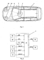
- Fig. 1 shows a plan view of a motor vehicle 1 with a - Fig. 2 in the form of a block diagram - occupant protection system.
- the occupant protection system includes at least one - not in Fig. 1 however in Fig. 2 shown - airbag 15 and / or one - not in Fig. 1 however in Fig. 2
- the seat-occupant protection system also comprises a control unit 2 for triggering the airbag 15 and / or the belt tensioner 16 and a crash sensor S2 integrated in the right front side of the motor vehicle 1 and a crash sensor S3 integrated in the left front side of the motor vehicle 1.
- the crash sensors S2 and S3 are connected to the control unit 2 by leads 5 and 6.
- the crash sensors S2 and S3 and another - as in Fig. 2 illustrated in the control unit 2 integrated - crash sensor S1 are formed according to the present embodiment as acceleration sensors.
- Suitable acceleration sensors are disclosed, for example, in the article published under the website www.informatik.uni-dortmund.de/airbag/seminarphase/hardware_vortrag.pdf "Hardware and Mechanics of Real Airbag Controls", Chapter 3.2 'Acceleration Sensor'.
- Suitable acceleration sensors are eg Bosch SMB060, Bosch PAS3 or Bosch UPF1.
- a suitable acceleration sensor may comprise, for example, a Bessel low-pass filter with a cutoff frequency of, for example, 400 Hz.
- the crash sensors S1, S2 and S3 deliver acceleration values aS1, aS2 and aS3 as output signals.
- the occupant protection system also comprises a belt sensor 11 for detecting whether a security good is applied, and for outputting a corresponding belt information MGURT.
- the occupant protection system further includes a seat occupancy sensor 12 for detecting whether or not a seat is occupied and outputting a corresponding seat occupancy information MSITZ.
- a suitable seat occupancy sensor is e.g. a pressure sensor integrated into the seat. Also suitable is an infrared scan disclosed in the article "Hardware and Mechanics of Real Airbag Controls" published under the website www.informatik.uni-dortmund.de/airbag/seminarphase/hardware_vortrag.pdf, Chapter 3.3 'Interior Sensing'.
- infrared scanning and fuzzy logic it is not only possible to detect whether a seat is occupied, but also whether it is an object such as a bag or a human being.
- CCD charged coupled devices
- Incident light releases charge carriers in each case.
- a signal generated in this way is amplified and processed or stored. This process is repeated at different angles to scan the seat.
- Image processing algorithms and fuzzy logic detect contours of objects and people from these signals.
- the occupant protection system comprises an operating element 14 for activating or deactivating the airbag 15.
- a corresponding switching signal is designated by the reference symbol EINAUS.
- the control unit 2 comprises a control module 10 for calculating and outputting an ignition signal AIR for the airbag 15 and / or an ignition signal GURT for the belt tensioner 16 as a function of the acceleration values aS1, aS2 and aS3, the belt information MGURT, the seat occupancy information MSITZ and the switching signal ONAUS ,
- Fig. 3 shows the control module 10 in an exemplary embodiment.
- the control module 10 comprises a trigger module 20 for calculating and outputting a spark advance CRASH as a function of the acceleration values aS1, aS2 and aS3.
- the control module 10 also includes a fire table 21 for calculating and outputting the ignition signal AIR for the airbag 15 and / or the ignition signal GURT for the belt tensioner 16 as a function of the ignition suggestion CRASH, the belt information MGURT, the seat occupancy information MSITZ and the switching signal ONAUS.
- the ignition signal AIR is equal to the ignition suggestion CRASH only when a corresponding seat is occupied by a person of a certain size, and that the ignition signal AIR is otherwise equal to zero.
- Both the ignition proposal CRASH and the ignition signals AIR and GURT can be ignition signals in the sense of the claims.
- Both the ignition suggestion CRASH and the ignition signals AIR and GURT can, for example, in the DE 100 35 505 A1 be described "binary signal corresponding to whether an occupant protection device, such as an airbag and / or a belt tensioner to be triggered.
- Both the ignition suggestion CRASH and the ignition signals AIR and GURT can also be a more complex signal.
- both the ignition suggestion CRASH and the ignition signal AIR may be a more complex signal indicating to what extent (eg stage 1 or stage 2) the airbag 15 should be fired.
- Both the ignition suggestion CRASH and the ignition signal AIR for example, also in the DE 100 35 505 A1 described crash severity parameter or an occupant acceleration or load. It can be provided that both the ignition suggestion CRASH and the ignition signals AIR and GURT can indicate the location and / or the direction of a collision.
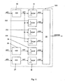
- Fig. 4 shows the trigger module 20 in an exemplary embodiment.
- the trip module 20 includes an A / D converter 25 for sampling the acceleration value aS1 and outputting a sampled acceleration value as1, an A / D converter 26 for sampling the acceleration value aS2, and outputting a sampled acceleration value as2 and an A / D converter 27 for sampling the acceleration value aS3 and outputting a sampled acceleration value as3.
- the sampling frequency of the ⁇ t of the A / D converters 25, 26 and 27 may be e.g. 4 kHz.
- the triggering module 20 also includes (digital) integrators 31, 32, 33, 34, 35 and 36.
- ⁇ 0 is the length of a time interval [t 0 - ⁇ 0 , t 0 ] or 40 (cf. Fig. 5 ).
- the time t 0 denotes the current time, ie the current value of the time t.
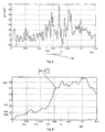
- Fig. 5 an exemplary course of the (sampled) acceleration value as1 over the time t in a head-on collision of the motor vehicle 1 with an obstacle.
- ⁇ 1 17 ms In the in Fig. 6 exemplary configuration shown is ⁇ 1 17 ms, ⁇ 2 34 ms and ⁇ 3 51 ms.
- ⁇ 1 can be 8 ms, ⁇ 2 16 ms and ⁇ 3 24 ms.
- the pseudo speed values v0S1, v1S1, v2S1, v3S1, v0S2 and v0S3 are examples of time averages in the sense of the invention.
- the tripping module 20 further comprises a tripping generator 30 for generating the ignition suggestion CRASH.
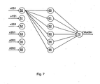
- the triggering generation 30 may be designed, for example, as a neural network, as shown in FIG Fig. 7 is shown in exemplary embodiment.
- the neural network shown comprises six input nodes 50, 51, 52, 53, 54, 55, six hidden nodes 60, 61, 62, 63, 64, 65 and one output node 70, each input node 50, 51, 52, 53, 54, 55 with each hidden node 60, 61, 62, 63, 64, 65 and each hidden node 60, 61, 62, 63, 64, 65 is connected to the output node 70.
- Fig. 7 However, for reasons of clarity, not all connections between the input nodes 50, 51, 52, 53, 54, 55 and the hidden nodes 60, 61, 62, 63, 64, 65 are shown.
- Input to the input node 50 is the pseudo speed value v0S1
- input to the input node 51 is the pseudo speed value v1S1
- input to the input node 52 is the pseudo speed value v2S1
- input to the input node 53 is the pseudo speed v3S1
- input to the input node 54 is the pseudo speed v0S2
- input to the input node 55 is the pseudo speed value v0S3.
- Output from the RavenASH is the ignition suggestion CRASH.
- neural networks can the US 5 583 771 , of the U.S. 5,684,701 as well as in the U.S. 5,684,701 cited documents " Techniques And Application Of Neural Networks ", Taylor, M. and Lisboa, Ellis Horwood, Westshire, England, 1993 , “ Naturally Intelligent Systems, “Caudill, M. and Butler, G., MIT Press, Cambridge, 1990 and " Digital Neural Networks, Kung, SY, PTR Prentice Hall, Eaglewood Cliffs, NJ, 1993 be removed.
- the tripping generation 30 can alternatively also be designed, for example, as a sequence of comparisons with limit values.
- Table 1 shows such a sequence of comparisons with thresholds wherein the code shown in Table 1 has been automatically generated by a learning method.
- ⁇ 1 is 4 ms
- ⁇ 2 is 8 ms
- ⁇ 0 is 24 ms.
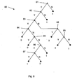
- Fig. 8 shows the code according to Table 1 in a representation as a decision tree 80.
- reference numeral 81 denotes the query whether v0S3 is smaller than a limit ⁇ v0S3 .
- Reference numeral 82 denotes the inquiry as to whether v0S2 is smaller than a threshold value ⁇ v0S2 .
- Reference numeral 83 denotes the inquiry as to whether v2S1 is smaller than a threshold value ⁇ v2S1 .
- Reference numeral 84 denotes the inquiry as to whether v0S1 is smaller than a threshold value ⁇ v0S1 .
- Reference numeral 85 denotes the inquiry as to whether v0S3 is smaller than a threshold value ⁇ v0S3,2 .
- Numeral 86 denotes the inquiry as to whether v0S1 is smaller than a threshold value ⁇ v0S1,2 .
- Numeral 87 denotes the inquiry as to whether v1S1 is smaller than a threshold value ⁇ v1S1 .
- Numeral 88 denotes the inquiry as to whether v0S2 is smaller than a threshold value ⁇ v0S2,2 .
- Numeral 89 denotes the inquiry as to whether v0S3 is smaller than a threshold value ⁇ v0S3,3 .
- the trip generation 30 according to Fig. 8 or Table 1 ignores the pseudo speed value v3S1. This has been taken into account in the learning process, but has been rejected by the learning algorithm for generating the code according to Table 1.
- Fig. 9 shows an alternative to the trigger module 20 trigger module 120 in an exemplary embodiment.
- the integrators 32, 33 and 34 are replaced with dead-time elements 132, 133 and 134, which are arranged such that v1S1 as the time ⁇ 1 delayed pseudo speed value v0S1, the pseudo speed value v2S1 as to the time of the pseudo velocity value ⁇ 2 delayed pseudo speed value v0S1 and the pseudo speed value v3S1 results as the pseudo speed value v0S1 delayed by the time ⁇ 3 .
- i is a run index indicating the current time t 0 and a constant.
- the pseudo speed values v0S1, v1S1, v2S1 and v3S1 result in this case, for example, according to the following relationships:
- Fig. 10 shows an alternative to the trigger module 20 trigger module 220 in an exemplary embodiment.
- the integrators 32, 33 and 34 are replaced by integrators 232, 233 and 234.
- time intervals differ in their position.
- the time intervals differ in their length. It can also be provided that time intervals differ in their length and in their position.
- a corresponding embodiment shows Fig. 11.
- Fig. 11 shows an actuation module 220 alternative actuation module 320 in an exemplary embodiment.
- the invention leads in particular in conjunction with neural networks, automatically generated decision trees or comparable learning evaluation methods to a particularly robust control of airbags and belt tensioners.
- the invention is not limited to this case.
- the invention is also applicable to side airbags and other occupant protection systems.
- the crash sensors S2 and S3 may be e.g. be arranged in the B-pillar. It can be provided that at least one pseudo speed value is also formed for at least one further time interval for the crash sensor S2 and / or the crash sensor S3.
- a control device according to the invention may also be a distributed system.
- a control device according to the invention need not be housed in a single housing.
- a control device according to the invention may also be a single chip or a circuit board.
- decision trees are mentioned or mentioned in connection with the generation of the ignition suggestion CRASH, these can also be replaced by regression trees, association tables, rule sets, supervector mashines or other mashine learning methods.
- differences of movement quantities mean values of these differences and / or differences of average values may also be used be used.
- differences of movement quantities mean values of these differences and / or differences of average values may also be used be used.
- difference values ⁇ out1, ⁇ as2, ⁇ as3 are input variables of the integrators 31, 32, 33, 34, 35, 36, 232, 233, 234 and 334, where ⁇ as1 is equal of the difference as1-as2, ⁇ as2 equal to the difference as1-as3 and ⁇ as3 equal to the difference as2-as3.
- the difference value ⁇ as1 is processed in the same way as the sampled acceleration value as1 in Fig. 4 . Fig. 9 . Fig. 10 and or Fig.
- Differences can also be temporal differences.
- difference values ⁇ as1, ⁇ as2, ⁇ as3 as input variables of the integrators 31, 32, 33, 34, 35, 36, 232, 233, 234 and 334, where ⁇ as1 ( t) equal to the difference as 1 (t) -as1 (t- ⁇ ), ⁇ as2 equal to the difference as2 (t) -as2 (t- ⁇ ) or the difference as2 (t) -as3 (t- ⁇ ) and ⁇ as3 is the difference as3 (t) -as3 (t- ⁇ ) or the difference as3 (t) -as2 (t- ⁇ ).
- motion quantities in the sense of the invention can also be differences of motion variables when they are used as input variables.
- mean values of motion quantities in the sense of the invention can also be differences of mean values of motion quantities or mean values of differences of motion quantities if they are used as input variables.
Landscapes
- Engineering & Computer Science (AREA)
- Mechanical Engineering (AREA)
- Radar, Positioning & Navigation (AREA)
- Remote Sensing (AREA)
- Air Bags (AREA)
- Superstructure Of Vehicle (AREA)
- Automotive Seat Belt Assembly (AREA)
- Air-Conditioning For Vehicles (AREA)
- Manufacture Of Motors, Generators (AREA)
- Control Of Multiple Motors (AREA)
- Control Of Direct Current Motors (AREA)
- Manufacturing Of Electrical Connectors (AREA)
- Installation Of Indoor Wiring (AREA)
- Arrangement Or Mounting Of Propulsion Units For Vehicles (AREA)
Applications Claiming Priority (5)
| Application Number | Priority Date | Filing Date | Title |
|---|---|---|---|
| DE10348998 | 2003-10-17 | ||
| DE10348997A DE10348997A1 (de) | 2003-10-17 | 2003-10-17 | Verfahren und Vorrichtung zur Steuerung von Sicherheitseinrichtungen in Kraftfahrzeugen |
| DE10348999A DE10348999A1 (de) | 2003-10-17 | 2003-10-17 | Verfahren und Vorrichtung zur Steuerung von Sicherheitseinrichtungen in Kraftfahrzeugen |
| DE102004004951 | 2004-01-31 | ||
| PCT/EP2004/011535 WO2005037611A1 (de) | 2003-10-17 | 2004-10-14 | Insassenschutzsystem für ein kraftfahrzeug |
Publications (2)
| Publication Number | Publication Date |
|---|---|
| EP1680312A1 EP1680312A1 (de) | 2006-07-19 |
| EP1680312B1 true EP1680312B1 (de) | 2013-01-02 |
Family
ID=34437700
Family Applications (6)
| Application Number | Title | Priority Date | Filing Date |
|---|---|---|---|
| EP04790395A Expired - Lifetime EP1680312B1 (de) | 2003-10-17 | 2004-10-14 | Insassenschutzsystem für ein kraftfahrzeug |
| EP04790393A Expired - Lifetime EP1680310B1 (de) | 2003-10-17 | 2004-10-14 | Verfahren zum herstellen eines kraftfahrzeuges |
| EP04790394A Expired - Lifetime EP1680311B1 (de) | 2003-10-17 | 2004-10-14 | Kraftfahrzeug mit einem insassenschutzsystem |
| EP04765960A Expired - Lifetime EP1678011B1 (de) | 2003-10-17 | 2004-10-14 | Verfahren zur erzeugung eines auslösezusammenhanges zum auslösen einer insassenschutzeinrichtung eines kraftfahrzeuges |
| EP04765961A Expired - Lifetime EP1678012B1 (de) | 2003-10-17 | 2004-10-14 | Verfahren zum herstellen eines kraftfahrzeuges |
| EP04790397A Expired - Lifetime EP1678014B1 (de) | 2003-10-17 | 2004-10-14 | Fussgängerschutzsystem für ein kraftfahrzeug |
Family Applications After (5)
| Application Number | Title | Priority Date | Filing Date |
|---|---|---|---|
| EP04790393A Expired - Lifetime EP1680310B1 (de) | 2003-10-17 | 2004-10-14 | Verfahren zum herstellen eines kraftfahrzeuges |
| EP04790394A Expired - Lifetime EP1680311B1 (de) | 2003-10-17 | 2004-10-14 | Kraftfahrzeug mit einem insassenschutzsystem |
| EP04765960A Expired - Lifetime EP1678011B1 (de) | 2003-10-17 | 2004-10-14 | Verfahren zur erzeugung eines auslösezusammenhanges zum auslösen einer insassenschutzeinrichtung eines kraftfahrzeuges |
| EP04765961A Expired - Lifetime EP1678012B1 (de) | 2003-10-17 | 2004-10-14 | Verfahren zum herstellen eines kraftfahrzeuges |
| EP04790397A Expired - Lifetime EP1678014B1 (de) | 2003-10-17 | 2004-10-14 | Fussgängerschutzsystem für ein kraftfahrzeug |
Country Status (7)
| Country | Link |
|---|---|
| US (2) | US8096579B2 (enExample) |
| EP (6) | EP1680312B1 (enExample) |
| JP (2) | JP2007508197A (enExample) |
| AT (4) | ATE393065T1 (enExample) |
| DE (3) | DE502004006950D1 (enExample) |
| ES (1) | ES2305865T3 (enExample) |
| WO (6) | WO2005035320A2 (enExample) |
Families Citing this family (16)
| Publication number | Priority date | Publication date | Assignee | Title |
|---|---|---|---|---|
| US7580782B2 (en) * | 1995-10-30 | 2009-08-25 | Automotive Technologies International, Inc. | Vehicular electronic system with crash sensors and occupant protection systems |
| DE102005038593A1 (de) * | 2005-08-16 | 2007-02-22 | Robert Bosch Gmbh | Kontaktsensorik für ein Fahrzeug |
| DE102006042455A1 (de) * | 2006-02-21 | 2007-08-23 | Volkswagen Ag | Gurtschloss für ein Kraftfahrzeug |
| DE102006044085B4 (de) * | 2006-09-20 | 2012-02-09 | Audi Ag | Kollisions- und/oder Personenschutzsystem für ein Kraftfahrzeug |
| DE102007027649B4 (de) | 2007-06-15 | 2015-10-01 | Robert Bosch Gmbh | Verfahren und Steuergerät zur Ansteuerung von Personenschutzmitteln sowie Computerprogramm und Computerprogrammprodukt |
| DE102007050254B4 (de) | 2007-10-20 | 2022-02-17 | Andata Entwicklungstechnologie Gmbh & Co.Kg | Verfahren zum Herstellen eines Kollisionsschutzsystems für ein Kraftfahrzeug |
| US8200595B1 (en) * | 2008-06-11 | 2012-06-12 | Fair Isaac Corporation | Determing a disposition of sensor-based events using decision trees with splits performed on decision keys |
| CN102137777B (zh) * | 2008-08-28 | 2015-07-29 | Trw汽车美国有限责任公司 | 用于控制可致动的安全设备的方法和装置 |
| DE102008045586B4 (de) | 2008-09-03 | 2017-09-14 | Audi Ag | Kollisions-und/oder Personenschutzsystem für ein Kraftfahrzeug und Verfahren dazu |
| JP5257610B2 (ja) * | 2009-03-10 | 2013-08-07 | 三菱自動車工業株式会社 | 車両の衝突検知構造 |
| US8762009B2 (en) * | 2010-11-18 | 2014-06-24 | I.D. Systems, Inc. | Impact sensor calibration tool |
| DE102011102298B4 (de) | 2011-05-23 | 2014-03-06 | Audi Ag | Verfahren zum Steuern von Rückhalteeinrichtungen eines Kraftfahrzeugs |
| CN104470763B (zh) * | 2012-05-22 | 2017-02-22 | Trw汽车美国有限责任公司 | 用于检测车辆/行人撞击的混合方法和装置 |
| DE102016205545A1 (de) * | 2016-04-04 | 2017-10-05 | Robert Bosch Gmbh | Verfahren zur Bestimmung einer Aufprallstärke |
| TWI641522B (zh) * | 2017-05-18 | 2018-11-21 | 晶翔微系統股份有限公司 | 減速警示裝置及方法 |
| US11304955B2 (en) | 2017-06-09 | 2022-04-19 | Isp Investments Llc | Small-molecule povidone analogs in coamorphous pharmaceutical phases |
Family Cites Families (36)
| Publication number | Priority date | Publication date | Assignee | Title |
|---|---|---|---|---|
| JPH0471933A (ja) * | 1990-07-10 | 1992-03-06 | Toyota Motor Corp | 車両用走行制御装置 |
| US5684701A (en) * | 1995-06-07 | 1997-11-04 | Automotive Technologies International, Inc. | Method and apparatus for sensing a vehicle crash |
| US7635043B2 (en) * | 1991-07-09 | 2009-12-22 | Automotive Technologies International, Inc. | Crash sensor arrangement for controlling deployment of an occupant restraint device |
| US5498028A (en) * | 1994-01-04 | 1996-03-12 | Trw Inc. | Method and apparatus for controlling an actuatable restraining device |
| GB2289786B (en) * | 1994-05-23 | 1998-09-16 | Automotive Tech Int | Side impact airbag system with anticipatory sensor |
| US5583771A (en) | 1994-08-04 | 1996-12-10 | Delco Electronics Corp. | Method and apparatus for distinguishing between deployment events and non-deployment events in an SIR system |
| GB2293681B (en) * | 1994-09-29 | 1998-08-12 | Autoliv Dev | Improvements in or relating to a safety arrangement |
| JPH09315261A (ja) * | 1996-05-30 | 1997-12-09 | Toyota Motor Corp | 積和演算回路学習方法及びその装置、並びに乗員保護装置の起動制御装置 |
| US6070113A (en) * | 1996-06-21 | 2000-05-30 | Automotive Systems Laboratory, Inc. | Hybrid vehicle crash discrimination system |
| JPH1067294A (ja) * | 1996-07-25 | 1998-03-10 | Automot Technol Internatl Inc | 車両の衝突を感知する方法および装置 |
| DE19724101A1 (de) * | 1997-06-07 | 1998-12-10 | Bayerische Motoren Werke Ag | Verfahren zur bedarfsgerechten Steuerung von Insassen-Sicherheitseinrichtungen |
| DE19729960A1 (de) * | 1997-07-12 | 1998-11-26 | Telefunken Microelectron | Verfahren zur Aufprallerkennung |
| US6561301B1 (en) * | 1998-02-24 | 2003-05-13 | Kabushiki Kaisha Toyota Chuo Kenkyusho | Collision discriminating apparatus for vehicles |
| US6186539B1 (en) * | 1998-07-01 | 2001-02-13 | Trw Inc. | Method and apparatus for controlling an actuatable restraint device using crash severity indexing and crush zone sensor |
| US6219606B1 (en) * | 1998-11-16 | 2001-04-17 | Delphi Technologies, Inc. | Restraint deployment control method having a delayed adaptable deployment threshold |
| DE19854380A1 (de) | 1998-11-25 | 2000-05-31 | Bayerische Motoren Werke Ag | Verfahren zum Erkennen der Schwere eines Fahrzeugzusammenstoßes |
| JP3436185B2 (ja) * | 1999-02-09 | 2003-08-11 | トヨタ自動車株式会社 | 乗員保護装置の起動制御装置 |
| DE19917710A1 (de) * | 1999-04-20 | 2000-10-26 | Bosch Gmbh Robert | Verfahren zur Bildung eines Auslösekriteriums für Rückhaltemittel |
| DE19928517C2 (de) | 1999-06-22 | 2001-09-06 | Pilz Gmbh & Co | Steuerungssystem zum Steuern von sicherheitskritischen Prozessen |
| JP4153129B2 (ja) * | 1999-07-14 | 2008-09-17 | オートリブ ディベロップメント エービー | シートベルト装置 |
| JP2001058552A (ja) * | 1999-08-04 | 2001-03-06 | Takata Corp | 車両衝突被害軽減システム |
| DE10016142B4 (de) | 2000-03-31 | 2010-01-21 | Volkswagen Ag | Auslöseschalter für ein Personenschutzsystem |
| DE10116142A1 (de) | 2000-04-05 | 2001-12-20 | Univ Ilmenau Tech | Verfahren zur Spracherkennung von Telefonsignalen |
| DE10035505A1 (de) * | 2000-07-21 | 2002-01-31 | Bayerische Motoren Werke Ag | Verfahren zum Erkennen der Schwere eines Fahrzeugzusammenstoßes |
| US6510914B2 (en) * | 2000-07-26 | 2003-01-28 | Honda Giken Kogyo Kabushiki Kaisha | Obstruction inference apparatus for vehicle |
| DE10040111A1 (de) | 2000-08-17 | 2002-02-28 | Bosch Gmbh Robert | Verfahren zur Bildung einer Auslöseentscheidung für Rückhaltemittel |
| JP3788286B2 (ja) * | 2001-01-19 | 2006-06-21 | トヨタ自動車株式会社 | 乗員保護装置の制御装置 |
| DE10103661C1 (de) | 2001-01-27 | 2002-08-08 | Bosch Gmbh Robert | Verfahren zur Seitenaufprallsensierung in einem Fahrzeug |
| DE10117220A1 (de) * | 2001-04-06 | 2002-10-10 | Conti Temic Microelectronic | Verfahren zur Auflösung eines Insassenschutzsystems in Fahrzeugen |
| US6529810B2 (en) * | 2001-04-09 | 2003-03-04 | Trw Inc. | Method and apparatus for controlling an actuatable restraining device using switched thresholds based on transverse acceleration |
| JP3608052B2 (ja) * | 2001-08-09 | 2005-01-05 | トヨタ自動車株式会社 | 乗員保護装置の起動制御装置 |
| JP3819274B2 (ja) * | 2001-10-16 | 2006-09-06 | 三菱電機株式会社 | 衝突形態判定装置および判定方法 |
| WO2003082639A1 (en) * | 2002-03-28 | 2003-10-09 | Autoliv Development Ab | An impact detector system |
| DE10227003A1 (de) * | 2002-06-18 | 2004-01-15 | Robert Bosch Gmbh | Verfahren zur Ansteuerung eines Rückhaltesystems |
| ITTO20021091A1 (it) * | 2002-12-17 | 2004-06-18 | Trw Occupant Safety Systems S P A | Metodo di controllo di un gruppo di movimentazione del cofano di un veicolo per la sicurezza dei pedoni in caso di urto contro il paraurti anteriore del veicolo stesso. |
| DE10305087B4 (de) * | 2003-02-07 | 2005-05-04 | Siemens Ag | Verfahren und Vorrichtung zum Steuern eines Insassenschutzmittels in einem Fahrzeug |
-
2004
- 2004-10-14 AT AT04790394T patent/ATE393065T1/de not_active IP Right Cessation
- 2004-10-14 AT AT04790397T patent/ATE552148T1/de active
- 2004-10-14 JP JP2006534682A patent/JP2007508197A/ja active Pending
- 2004-10-14 WO PCT/EP2004/011538 patent/WO2005035320A2/de not_active Ceased
- 2004-10-14 US US10/576,063 patent/US8096579B2/en active Active
- 2004-10-14 EP EP04790395A patent/EP1680312B1/de not_active Expired - Lifetime
- 2004-10-14 EP EP04790393A patent/EP1680310B1/de not_active Expired - Lifetime
- 2004-10-14 WO PCT/EP2004/011533 patent/WO2005037610A1/de not_active Ceased
- 2004-10-14 DE DE502004006950T patent/DE502004006950D1/de not_active Expired - Lifetime
- 2004-10-14 WO PCT/EP2004/011535 patent/WO2005037611A1/de not_active Ceased
- 2004-10-14 WO PCT/EP2004/011537 patent/WO2005037612A1/de not_active Ceased
- 2004-10-14 EP EP04790394A patent/EP1680311B1/de not_active Expired - Lifetime
- 2004-10-14 EP EP04765960A patent/EP1678011B1/de not_active Expired - Lifetime
- 2004-10-14 AT AT04765960T patent/ATE381466T1/de not_active IP Right Cessation
- 2004-10-14 ES ES04790394T patent/ES2305865T3/es not_active Expired - Lifetime
- 2004-10-14 WO PCT/EP2004/011534 patent/WO2005035319A1/de not_active Ceased
- 2004-10-14 EP EP04765961A patent/EP1678012B1/de not_active Expired - Lifetime
- 2004-10-14 DE DE502004005768T patent/DE502004005768D1/de not_active Expired - Lifetime
- 2004-10-14 DE DE502004005769T patent/DE502004005769D1/de not_active Expired - Lifetime
- 2004-10-14 US US10/576,062 patent/US7379804B2/en not_active Expired - Lifetime
- 2004-10-14 JP JP2006534681A patent/JP4970945B2/ja not_active Expired - Lifetime
- 2004-10-14 AT AT04765961T patent/ATE381467T1/de not_active IP Right Cessation
- 2004-10-14 WO PCT/EP2004/011532 patent/WO2005037609A1/de not_active Ceased
- 2004-10-14 EP EP04790397A patent/EP1678014B1/de not_active Expired - Lifetime
Also Published As
Similar Documents
| Publication | Publication Date | Title |
|---|---|---|
| DE102007057727B4 (de) | Fußgängerkollisionserfassungsvorrichtung und Fußgängerschutzsystem | |
| EP1680311B1 (de) | Kraftfahrzeug mit einem insassenschutzsystem | |
| DE10065518B4 (de) | Verfahren zum Auslösen von Rückhaltemitteln in einem Kraftfahrzeug | |
| DE19743009B4 (de) | Verfahren und Vorrichtung zur Einzelpunktabfühlung von vorderen und seitlichen Aufschlagzusammenstoßbedingungen | |
| EP0458796B1 (de) | Verfahren zur auslösung von rückhaltemitteln | |
| DE10215386B4 (de) | Verfahren und Vorrichtung zum Steuern einer betätigbaren Rückhalteeinrichtung, die geschaltete Schwellenwerte basierend auf Querbeschleunigung verwendet | |
| EP1409297B1 (de) | Verfahren und vorrichtung zur ansteuerung der auslösung von passiven sicherheitssystemen sowie anwendung davon | |
| EP1296859A1 (de) | Verfahren und vorrichtung zum erkennen eines fussgangeraufpralls | |
| DE102005059255B4 (de) | Verfahren und Vorrichtung zum Bestimmen symmetrischer und asymmetrischer Zusammenstoßereignisse mit verbesserten Fehlfunktionstoleranzen | |
| EP1420983B1 (de) | Verfahren zur auslösung wenigstens eines airbags in einem fahrzeug | |
| DE10157203B4 (de) | Passives Sicherheitssystem | |
| EP1133418B1 (de) | Verfahren zum erkennen der schwere eines fahrzeugzusammenstosses | |
| EP1551670B1 (de) | Verfahren zur auslösung eines rückhaltesystems in einem fahrzeug | |
| EP1334010B1 (de) | Rückhaltesystem mit einer rückhalteeinrichtung zum schutz wenigstens eines passagiers und verfahren zur steuerung eines rückhaltesystems | |
| DE10239406A1 (de) | Vorrichtung zur Erkennung eines Fahrzeugüberschlags | |
| EP1902908B1 (de) | Kollisions- und/oder Personenschutzsystem für ein Kraftfahrzeug | |
| EP1551671B1 (de) | Vorrichtung zur ansteuerung eines rückhaltesystems | |
| DE102007004345B4 (de) | Verfahren und Steuergerät zur Ansteuerung von Personenschutzmitteln | |
| DE10348999A1 (de) | Verfahren und Vorrichtung zur Steuerung von Sicherheitseinrichtungen in Kraftfahrzeugen | |
| DE19812830B4 (de) | Verfahren und Vorrichtung zur Auslösung eines Airbags mit Sitzpositionserkennung | |
| DE10155751B4 (de) | Verfahren zum Untersuchen einer für das Auslösen einer passiven Sicherheitseinrichtung in einem Fahrzeug maßgeblichen Fahrzeugbeschleunigung | |
| DE102005015738B4 (de) | Verfahren zur Erzeugung eines Auslösesignals für Insassenschutzsysteme | |
| DE102006056836A1 (de) | Verfahren und Vorrichtung zur Ansteuerung von Personenschutzmitteln | |
| DE19547830A1 (de) | Airbagsystem |
Legal Events
| Date | Code | Title | Description |
|---|---|---|---|
| PUAI | Public reference made under article 153(3) epc to a published international application that has entered the european phase |
Free format text: ORIGINAL CODE: 0009012 |
|
| 17P | Request for examination filed |
Effective date: 20060517 |
|
| AK | Designated contracting states |
Kind code of ref document: A1 Designated state(s): AT BE BG CH CY CZ DE DK EE ES FI FR GB GR HU IE IT LI LU MC NL PL PT RO SE SI SK TR |
|
| 17Q | First examination report despatched |
Effective date: 20061115 |
|
| DAX | Request for extension of the european patent (deleted) | ||
| REG | Reference to a national code |
Ref country code: DE Ref legal event code: R079 Ref document number: 502004013979 Country of ref document: DE Free format text: PREVIOUS MAIN CLASS: B60R0021010000 Ipc: B60R0021013200 |
|
| RAP1 | Party data changed (applicant data changed or rights of an application transferred) |
Owner name: AUDI AG Owner name: ANDATA ENTWICKLUNGSTECHNOLOGIE GMBH & CO. KG Owner name: VOLKSWAGEN AKTIENGESELLSCHAFT |
|
| GRAP | Despatch of communication of intention to grant a patent |
Free format text: ORIGINAL CODE: EPIDOSNIGR1 |
|
| RIC1 | Information provided on ipc code assigned before grant |
Ipc: B60R 21/0132 20060101AFI20120627BHEP Ipc: B60R 21/0134 20060101ALI20120627BHEP |
|
| GRAS | Grant fee paid |
Free format text: ORIGINAL CODE: EPIDOSNIGR3 |
|
| GRAA | (expected) grant |
Free format text: ORIGINAL CODE: 0009210 |
|
| AK | Designated contracting states |
Kind code of ref document: B1 Designated state(s): AT BE BG CH CY CZ DE DK EE ES FI FR GB GR HU IE IT LI LU MC NL PL PT RO SE SI SK TR |
|
| REG | Reference to a national code |
Ref country code: GB Ref legal event code: FG4D Free format text: NOT ENGLISH |
|
| REG | Reference to a national code |
Ref country code: CH Ref legal event code: EP Ref country code: AT Ref legal event code: REF Ref document number: 591407 Country of ref document: AT Kind code of ref document: T Effective date: 20130115 |
|
| REG | Reference to a national code |
Ref country code: IE Ref legal event code: FG4D Free format text: LANGUAGE OF EP DOCUMENT: GERMAN |
|
| REG | Reference to a national code |
Ref country code: DE Ref legal event code: R096 Ref document number: 502004013979 Country of ref document: DE Effective date: 20130307 |
|
| REG | Reference to a national code |
Ref country code: NL Ref legal event code: VDEP Effective date: 20130102 |
|
| PG25 | Lapsed in a contracting state [announced via postgrant information from national office to epo] |
Ref country code: SI Free format text: LAPSE BECAUSE OF FAILURE TO SUBMIT A TRANSLATION OF THE DESCRIPTION OR TO PAY THE FEE WITHIN THE PRESCRIBED TIME-LIMIT Effective date: 20130102 |
|
| PG25 | Lapsed in a contracting state [announced via postgrant information from national office to epo] |
Ref country code: BG Free format text: LAPSE BECAUSE OF FAILURE TO SUBMIT A TRANSLATION OF THE DESCRIPTION OR TO PAY THE FEE WITHIN THE PRESCRIBED TIME-LIMIT Effective date: 20130402 Ref country code: ES Free format text: LAPSE BECAUSE OF FAILURE TO SUBMIT A TRANSLATION OF THE DESCRIPTION OR TO PAY THE FEE WITHIN THE PRESCRIBED TIME-LIMIT Effective date: 20130413 Ref country code: CY Free format text: LAPSE BECAUSE OF FAILURE TO SUBMIT A TRANSLATION OF THE DESCRIPTION OR TO PAY THE FEE WITHIN THE PRESCRIBED TIME-LIMIT Effective date: 20130102 Ref country code: SE Free format text: LAPSE BECAUSE OF FAILURE TO SUBMIT A TRANSLATION OF THE DESCRIPTION OR TO PAY THE FEE WITHIN THE PRESCRIBED TIME-LIMIT Effective date: 20130102 Ref country code: CZ Free format text: LAPSE BECAUSE OF FAILURE TO SUBMIT A TRANSLATION OF THE DESCRIPTION OR TO PAY THE FEE WITHIN THE PRESCRIBED TIME-LIMIT Effective date: 20130102 |
|
| PG25 | Lapsed in a contracting state [announced via postgrant information from national office to epo] |
Ref country code: PL Free format text: LAPSE BECAUSE OF FAILURE TO SUBMIT A TRANSLATION OF THE DESCRIPTION OR TO PAY THE FEE WITHIN THE PRESCRIBED TIME-LIMIT Effective date: 20130102 Ref country code: FI Free format text: LAPSE BECAUSE OF FAILURE TO SUBMIT A TRANSLATION OF THE DESCRIPTION OR TO PAY THE FEE WITHIN THE PRESCRIBED TIME-LIMIT Effective date: 20130102 Ref country code: PT Free format text: LAPSE BECAUSE OF FAILURE TO SUBMIT A TRANSLATION OF THE DESCRIPTION OR TO PAY THE FEE WITHIN THE PRESCRIBED TIME-LIMIT Effective date: 20130502 Ref country code: NL Free format text: LAPSE BECAUSE OF FAILURE TO SUBMIT A TRANSLATION OF THE DESCRIPTION OR TO PAY THE FEE WITHIN THE PRESCRIBED TIME-LIMIT Effective date: 20130102 Ref country code: GR Free format text: LAPSE BECAUSE OF FAILURE TO SUBMIT A TRANSLATION OF THE DESCRIPTION OR TO PAY THE FEE WITHIN THE PRESCRIBED TIME-LIMIT Effective date: 20130403 |
|
| PG25 | Lapsed in a contracting state [announced via postgrant information from national office to epo] |
Ref country code: DK Free format text: LAPSE BECAUSE OF FAILURE TO SUBMIT A TRANSLATION OF THE DESCRIPTION OR TO PAY THE FEE WITHIN THE PRESCRIBED TIME-LIMIT Effective date: 20130102 Ref country code: SK Free format text: LAPSE BECAUSE OF FAILURE TO SUBMIT A TRANSLATION OF THE DESCRIPTION OR TO PAY THE FEE WITHIN THE PRESCRIBED TIME-LIMIT Effective date: 20130102 Ref country code: EE Free format text: LAPSE BECAUSE OF FAILURE TO SUBMIT A TRANSLATION OF THE DESCRIPTION OR TO PAY THE FEE WITHIN THE PRESCRIBED TIME-LIMIT Effective date: 20130102 Ref country code: RO Free format text: LAPSE BECAUSE OF FAILURE TO SUBMIT A TRANSLATION OF THE DESCRIPTION OR TO PAY THE FEE WITHIN THE PRESCRIBED TIME-LIMIT Effective date: 20130102 |
|
| PLBE | No opposition filed within time limit |
Free format text: ORIGINAL CODE: 0009261 |
|
| STAA | Information on the status of an ep patent application or granted ep patent |
Free format text: STATUS: NO OPPOSITION FILED WITHIN TIME LIMIT |
|
| 26N | No opposition filed |
Effective date: 20131003 |
|
| REG | Reference to a national code |
Ref country code: DE Ref legal event code: R097 Ref document number: 502004013979 Country of ref document: DE Effective date: 20131003 |
|
| BERE | Be: lapsed |
Owner name: AUDI A.G. Effective date: 20131031 Owner name: ANDATA ENTWICKLUNGSTECHNOLOGIE GMBH & CO. KG Effective date: 20131031 Owner name: VOLKSWAGEN A.G. Effective date: 20131031 |
|
| PG25 | Lapsed in a contracting state [announced via postgrant information from national office to epo] |
Ref country code: MC Free format text: LAPSE BECAUSE OF FAILURE TO SUBMIT A TRANSLATION OF THE DESCRIPTION OR TO PAY THE FEE WITHIN THE PRESCRIBED TIME-LIMIT Effective date: 20130102 |
|
| REG | Reference to a national code |
Ref country code: CH Ref legal event code: PL |
|
| REG | Reference to a national code |
Ref country code: IE Ref legal event code: MM4A |
|
| PG25 | Lapsed in a contracting state [announced via postgrant information from national office to epo] |
Ref country code: CH Free format text: LAPSE BECAUSE OF NON-PAYMENT OF DUE FEES Effective date: 20131031 Ref country code: LI Free format text: LAPSE BECAUSE OF NON-PAYMENT OF DUE FEES Effective date: 20131031 |
|
| PG25 | Lapsed in a contracting state [announced via postgrant information from national office to epo] |
Ref country code: BE Free format text: LAPSE BECAUSE OF NON-PAYMENT OF DUE FEES Effective date: 20131031 |
|
| PG25 | Lapsed in a contracting state [announced via postgrant information from national office to epo] |
Ref country code: IE Free format text: LAPSE BECAUSE OF NON-PAYMENT OF DUE FEES Effective date: 20131014 |
|
| REG | Reference to a national code |
Ref country code: AT Ref legal event code: MM01 Ref document number: 591407 Country of ref document: AT Kind code of ref document: T Effective date: 20131014 |
|
| PG25 | Lapsed in a contracting state [announced via postgrant information from national office to epo] |
Ref country code: AT Free format text: LAPSE BECAUSE OF NON-PAYMENT OF DUE FEES Effective date: 20131014 |
|
| PG25 | Lapsed in a contracting state [announced via postgrant information from national office to epo] |
Ref country code: TR Free format text: LAPSE BECAUSE OF FAILURE TO SUBMIT A TRANSLATION OF THE DESCRIPTION OR TO PAY THE FEE WITHIN THE PRESCRIBED TIME-LIMIT Effective date: 20130102 |
|
| PG25 | Lapsed in a contracting state [announced via postgrant information from national office to epo] |
Ref country code: HU Free format text: LAPSE BECAUSE OF FAILURE TO SUBMIT A TRANSLATION OF THE DESCRIPTION OR TO PAY THE FEE WITHIN THE PRESCRIBED TIME-LIMIT; INVALID AB INITIO Effective date: 20041014 Ref country code: LU Free format text: LAPSE BECAUSE OF NON-PAYMENT OF DUE FEES Effective date: 20131014 |
|
| REG | Reference to a national code |
Ref country code: FR Ref legal event code: PLFP Year of fee payment: 12 |
|
| REG | Reference to a national code |
Ref country code: FR Ref legal event code: PLFP Year of fee payment: 13 |
|
| REG | Reference to a national code |
Ref country code: FR Ref legal event code: PLFP Year of fee payment: 14 |
|
| REG | Reference to a national code |
Ref country code: FR Ref legal event code: PLFP Year of fee payment: 15 |
|
| P01 | Opt-out of the competence of the unified patent court (upc) registered |
Effective date: 20230606 |
|
| PGFP | Annual fee paid to national office [announced via postgrant information from national office to epo] |
Ref country code: GB Payment date: 20231024 Year of fee payment: 20 |
|
| PGFP | Annual fee paid to national office [announced via postgrant information from national office to epo] |
Ref country code: IT Payment date: 20231024 Year of fee payment: 20 Ref country code: FR Payment date: 20231026 Year of fee payment: 20 Ref country code: DE Payment date: 20231031 Year of fee payment: 20 |
|
| REG | Reference to a national code |
Ref country code: DE Ref legal event code: R071 Ref document number: 502004013979 Country of ref document: DE |
|
| REG | Reference to a national code |
Ref country code: GB Ref legal event code: PE20 Expiry date: 20241013 |
|
| PG25 | Lapsed in a contracting state [announced via postgrant information from national office to epo] |
Ref country code: GB Free format text: LAPSE BECAUSE OF EXPIRATION OF PROTECTION Effective date: 20241013 |
|
| PG25 | Lapsed in a contracting state [announced via postgrant information from national office to epo] |
Ref country code: GB Free format text: LAPSE BECAUSE OF EXPIRATION OF PROTECTION Effective date: 20241013 |