EP1680312B1 - Occupant protection system for a motor vehicle - Google Patents
Occupant protection system for a motor vehicle Download PDFInfo
- Publication number
- EP1680312B1 EP1680312B1 EP04790395A EP04790395A EP1680312B1 EP 1680312 B1 EP1680312 B1 EP 1680312B1 EP 04790395 A EP04790395 A EP 04790395A EP 04790395 A EP04790395 A EP 04790395A EP 1680312 B1 EP1680312 B1 EP 1680312B1
- Authority
- EP
- European Patent Office
- Prior art keywords
- occupant protection
- crash
- protection system
- motor vehicle
- time interval
- Prior art date
- Legal status (The legal status is an assumption and is not a legal conclusion. Google has not performed a legal analysis and makes no representation as to the accuracy of the status listed.)
- Active
Links
- 230000001133 acceleration Effects 0.000 claims description 48
- 238000000034 method Methods 0.000 claims description 13
- 238000010304 firing Methods 0.000 claims 7
- 238000013528 artificial neural network Methods 0.000 description 10
- 230000006870 function Effects 0.000 description 10
- 238000003066 decision tree Methods 0.000 description 5
- 238000005070 sampling Methods 0.000 description 4
- 230000003111 delayed effect Effects 0.000 description 3
- 230000004044 response Effects 0.000 description 3
- 230000015572 biosynthetic process Effects 0.000 description 2
- 238000001514 detection method Methods 0.000 description 2
- 238000006073 displacement reaction Methods 0.000 description 2
- 238000011156 evaluation Methods 0.000 description 2
- 239000011159 matrix material Substances 0.000 description 2
- 230000008569 process Effects 0.000 description 2
- 230000001960 triggered effect Effects 0.000 description 2
- 101000623895 Bos taurus Mucin-15 Proteins 0.000 description 1
- 241000934790 Daphne mezereum Species 0.000 description 1
- 101000579423 Homo sapiens Regulator of nonsense transcripts 1 Proteins 0.000 description 1
- 102100028287 Regulator of nonsense transcripts 1 Human genes 0.000 description 1
- 230000003213 activating effect Effects 0.000 description 1
- 230000004913 activation Effects 0.000 description 1
- 230000008859 change Effects 0.000 description 1
- 239000002800 charge carrier Substances 0.000 description 1
- 238000002485 combustion reaction Methods 0.000 description 1
- 238000010586 diagram Methods 0.000 description 1
- 230000000694 effects Effects 0.000 description 1
- 239000000835 fiber Substances 0.000 description 1
- 230000000452 restraining effect Effects 0.000 description 1
- 230000035945 sensitivity Effects 0.000 description 1
- 230000002123 temporal effect Effects 0.000 description 1
Images


Classifications
-
- B—PERFORMING OPERATIONS; TRANSPORTING
- B60—VEHICLES IN GENERAL
- B60R—VEHICLES, VEHICLE FITTINGS, OR VEHICLE PARTS, NOT OTHERWISE PROVIDED FOR
- B60R21/00—Arrangements or fittings on vehicles for protecting or preventing injuries to occupants or pedestrians in case of accidents or other traffic risks
- B60R21/01—Electrical circuits for triggering passive safety arrangements, e.g. airbags, safety belt tighteners, in case of vehicle accidents or impending vehicle accidents
- B60R21/013—Electrical circuits for triggering passive safety arrangements, e.g. airbags, safety belt tighteners, in case of vehicle accidents or impending vehicle accidents including means for detecting collisions, impending collisions or roll-over
- B60R21/0132—Electrical circuits for triggering passive safety arrangements, e.g. airbags, safety belt tighteners, in case of vehicle accidents or impending vehicle accidents including means for detecting collisions, impending collisions or roll-over responsive to vehicle motion parameters, e.g. to vehicle longitudinal or transversal deceleration or speed value
-
- B—PERFORMING OPERATIONS; TRANSPORTING
- B60—VEHICLES IN GENERAL
- B60R—VEHICLES, VEHICLE FITTINGS, OR VEHICLE PARTS, NOT OTHERWISE PROVIDED FOR
- B60R21/00—Arrangements or fittings on vehicles for protecting or preventing injuries to occupants or pedestrians in case of accidents or other traffic risks
- B60R21/01—Electrical circuits for triggering passive safety arrangements, e.g. airbags, safety belt tighteners, in case of vehicle accidents or impending vehicle accidents
- B60R21/013—Electrical circuits for triggering passive safety arrangements, e.g. airbags, safety belt tighteners, in case of vehicle accidents or impending vehicle accidents including means for detecting collisions, impending collisions or roll-over
- B60R21/0134—Electrical circuits for triggering passive safety arrangements, e.g. airbags, safety belt tighteners, in case of vehicle accidents or impending vehicle accidents including means for detecting collisions, impending collisions or roll-over responsive to imminent contact with an obstacle, e.g. using radar systems
-
- B—PERFORMING OPERATIONS; TRANSPORTING
- B60—VEHICLES IN GENERAL
- B60R—VEHICLES, VEHICLE FITTINGS, OR VEHICLE PARTS, NOT OTHERWISE PROVIDED FOR
- B60R21/00—Arrangements or fittings on vehicles for protecting or preventing injuries to occupants or pedestrians in case of accidents or other traffic risks
- B60R21/01—Electrical circuits for triggering passive safety arrangements, e.g. airbags, safety belt tighteners, in case of vehicle accidents or impending vehicle accidents
- B60R21/013—Electrical circuits for triggering passive safety arrangements, e.g. airbags, safety belt tighteners, in case of vehicle accidents or impending vehicle accidents including means for detecting collisions, impending collisions or roll-over
- B60R21/0136—Electrical circuits for triggering passive safety arrangements, e.g. airbags, safety belt tighteners, in case of vehicle accidents or impending vehicle accidents including means for detecting collisions, impending collisions or roll-over responsive to actual contact with an obstacle, e.g. to vehicle deformation, bumper displacement or bumper velocity relative to the vehicle
-
- B—PERFORMING OPERATIONS; TRANSPORTING
- B60—VEHICLES IN GENERAL
- B60R—VEHICLES, VEHICLE FITTINGS, OR VEHICLE PARTS, NOT OTHERWISE PROVIDED FOR
- B60R21/00—Arrangements or fittings on vehicles for protecting or preventing injuries to occupants or pedestrians in case of accidents or other traffic risks
- B60R21/01—Electrical circuits for triggering passive safety arrangements, e.g. airbags, safety belt tighteners, in case of vehicle accidents or impending vehicle accidents
- B60R21/015—Electrical circuits for triggering passive safety arrangements, e.g. airbags, safety belt tighteners, in case of vehicle accidents or impending vehicle accidents including means for detecting the presence or position of passengers, passenger seats or child seats, and the related safety parameters therefor, e.g. speed or timing of airbag inflation in relation to occupant position or seat belt use
- B60R21/01512—Passenger detection systems
-
- B—PERFORMING OPERATIONS; TRANSPORTING
- B60—VEHICLES IN GENERAL
- B60R—VEHICLES, VEHICLE FITTINGS, OR VEHICLE PARTS, NOT OTHERWISE PROVIDED FOR
- B60R21/00—Arrangements or fittings on vehicles for protecting or preventing injuries to occupants or pedestrians in case of accidents or other traffic risks
- B60R21/01—Electrical circuits for triggering passive safety arrangements, e.g. airbags, safety belt tighteners, in case of vehicle accidents or impending vehicle accidents
- B60R21/015—Electrical circuits for triggering passive safety arrangements, e.g. airbags, safety belt tighteners, in case of vehicle accidents or impending vehicle accidents including means for detecting the presence or position of passengers, passenger seats or child seats, and the related safety parameters therefor, e.g. speed or timing of airbag inflation in relation to occupant position or seat belt use
- B60R21/01564—Manually or key-actuated inhibition switches
-
- B—PERFORMING OPERATIONS; TRANSPORTING
- B60—VEHICLES IN GENERAL
- B60R—VEHICLES, VEHICLE FITTINGS, OR VEHICLE PARTS, NOT OTHERWISE PROVIDED FOR
- B60R21/00—Arrangements or fittings on vehicles for protecting or preventing injuries to occupants or pedestrians in case of accidents or other traffic risks
- B60R21/01—Electrical circuits for triggering passive safety arrangements, e.g. airbags, safety belt tighteners, in case of vehicle accidents or impending vehicle accidents
- B60R2021/01034—Controlling a plurality of restraint devices
-
- B—PERFORMING OPERATIONS; TRANSPORTING
- B60—VEHICLES IN GENERAL
- B60R—VEHICLES, VEHICLE FITTINGS, OR VEHICLE PARTS, NOT OTHERWISE PROVIDED FOR
- B60R21/00—Arrangements or fittings on vehicles for protecting or preventing injuries to occupants or pedestrians in case of accidents or other traffic risks
- B60R21/01—Electrical circuits for triggering passive safety arrangements, e.g. airbags, safety belt tighteners, in case of vehicle accidents or impending vehicle accidents
- B60R2021/01204—Actuation parameters of safety arrangents
- B60R2021/01252—Devices other than bags
- B60R2021/01265—Seat belts
- B60R2021/01272—Belt tensioners
-
- B—PERFORMING OPERATIONS; TRANSPORTING
- B60—VEHICLES IN GENERAL
- B60R—VEHICLES, VEHICLE FITTINGS, OR VEHICLE PARTS, NOT OTHERWISE PROVIDED FOR
- B60R21/00—Arrangements or fittings on vehicles for protecting or preventing injuries to occupants or pedestrians in case of accidents or other traffic risks
- B60R21/01—Electrical circuits for triggering passive safety arrangements, e.g. airbags, safety belt tighteners, in case of vehicle accidents or impending vehicle accidents
- B60R21/015—Electrical circuits for triggering passive safety arrangements, e.g. airbags, safety belt tighteners, in case of vehicle accidents or impending vehicle accidents including means for detecting the presence or position of passengers, passenger seats or child seats, and the related safety parameters therefor, e.g. speed or timing of airbag inflation in relation to occupant position or seat belt use
- B60R21/01512—Passenger detection systems
- B60R21/01544—Passenger detection systems detecting seat belt parameters, e.g. length, tension or height-adjustment
Abstract
Description
Die Erfindung betrifft ein Insassenschutzsystem für ein Kraftfahrzeug. Ein derartiges Insassenschutzsystem kann einen Airbag und/oder einen Gurtstraffer umfassen.The invention relates to an occupant protection system for a motor vehicle. Such occupant protection system may include an airbag and / or a belt tensioner.
Airbagsysteme sind z.B. in dem unter der Internetseite www.informatik.uni-dortmund.de/airbag/seminarphase/hardware_vortrag.pdf veröffentlichten Artikel "Hardware und Mechanik realer Airbagsteuerungen" offenbart.Airbag systems are e.g. in the article published under the website www.informatik.uni-dortmund.de/airbag/seminarphase/hardware_vortrag.pdf "hardware and mechanics of real airbag controls" revealed.
Die
Die
Die
Aus der
In der
Die
Die
Es ist Aufgabe der Erfindung, ein verbessertes, insbesondere einen Airbag und/oder einen Gurtstraffer umfassendes, Insassenschutzsystem für ein Kraftfahrzeug anzugeben. Dabei ist es besonders wünschenswert, eine besonders präzise Auslösung eines solchen Insassenschutzsystems für ein Kraftfahrzeug anzugeben.It is an object of the invention to provide an improved, in particular an airbag and / or a belt tensioner comprehensive, occupant protection system for a motor vehicle. It is particularly desirable to specify a particularly precise triggering of such an occupant protection system for a motor vehicle.
Vorgenannte Aufgabe wird durch ein Insassenschutzsystem für ein Kraftfahrzeug mit zumindest einem Crashsensor zum Messen einer Bewegungsgröße des Kraftfahrzeuges gelöst, wobei das Insassenschutzsystem eine mittels eines Zündsignals steuerbare Insassenschutzeinrichtung und ein Steuergerät zur Ermittlung bzw. Erzeugung des Zündsignals in Abhängigkeit eines zeitlichen Mittelwertes der mittels des Crashsensors gemessenen Bewegungsgröße über zumindest ein erstes Zeitintervall und eines zeitlichen Mittelwertes der mittels des Crashsensors gemessenen Bewegungsgröße über ein zweites, von dem ersten Zeitintervall verschiedenes, Zeitintervall umfasst.The aforementioned object is achieved by an occupant protection system for a motor vehicle having at least one crash sensor for measuring a movement variable of the motor vehicle, wherein the occupant protection system measures an occupant protection device controllable by means of an ignition signal and a control device for determining or generating the ignition signal as a function of a time average value of the crash sensor Movement size over at least a first time interval and a time average value of the measured by the crash sensor amount of movement over a second, different from the first time interval, time interval.
Eine Insassenschutzeinrichtung im Sinne der Erfindung ist insbesondere ein Airbag und/oder ein Gurtstraffer.An occupant protection device according to the invention is in particular an airbag and / or a belt tensioner.
Ein Mittelwert im Sinne der Erfindung kann ein arithmetischer Mittelwert oder ein gewichteter Mittelwert sein. Bei einem derartigen gewichteten Mittelwert können z.B. jüngere Werte der Bewegungsgröße in dem betreffenden Zeitintervall stärker gewichtet werden als ältere Werte der Bewegungsgröße in dem betreffenden Zeitintervall. Ein Mittelwert im Sinne der Erfindung kann auch ein einem Mittelwert proportionaler Wert sein. In vorteilhafter Ausgestaltung der Erfindung ist der Mittelwert ein dem arithmetischen Mittelwert proportionaler Wert. Dabei ist der Mittelwert vorteilhafterweise ein dem Integral der Bewegungsgröße in dem betreffenden Zeitintervall bzw. der Summe von Abtastwerten der Bewegungsgröße in dem betreffenden Zeitintervall proportionaler Wert.An average within the meaning of the invention may be an arithmetic mean or a weighted average. With such a weighted mean value, for example, younger values of the movement variable in the relevant time interval can be weighted more heavily than older values of the movement variable in the relevant time interval. An average within the meaning of the invention may also be a mean value proportional value. In an advantageous embodiment of the invention, the mean value is a value proportional to the arithmetic mean value. In this case, the mean value is advantageously an integral of the motion variable in the relevant one Time interval or the sum of samples of the motion variable in the relevant time interval proportional value.
Eine Bewegungsgröße des Kraftfahrzeuges im Sinne der Erfindung kann eine Beschleunigung, eine Geschwindigkeit oder ein Weg bzw. eine von diesen Größen abgeleitete Größe sein. Die Bewegungsgröße ist dabei vorteilhafterweise eine Beschleunigung.A movement quantity of the motor vehicle in the sense of the invention may be an acceleration, a speed or a path or a variable derived from these variables. The amount of movement is advantageously an acceleration.
Ein Crashsensor im Sinne der Erfindung kann ein Beschleunigungssensor zum Messen einer Beschleunigung in eine oder mehrere Richtungen sein. Ein Crashsensor im Sinne der Erfindung kann auch ein Radargerät, eine Infrarotanordnung oder eine Kamera sein. In diesem Fall kann eine Bewegungsgröße des Kraftfahrzeuges ein Abstand des Kraftfahrzeuges zu einem Hindernis, die erste oder zweite Ableitung dieses Abstandes oder eine andere äquivalente Größe sein. Ein Crashsensor im Sinne der Erfindung kann auch ein Sensor zur Messung einer Deformation des Kraftfahrzeuges sein. Ein solcher Sensor kann ein faseroptischer Sensor oder ein in der
Ein Zündsignal im Sinne der Erfindung kann ein binäres Signal sein, das angibt, ob eine Insassenschutzeinrichtung, wie ein Airbag und/oder ein Gurtstraffer, ausgelöst werden soll. Ein solches Zündsignal im Sinne der Erfindung kann ein in der
Ein zweites, von einem ersten Zeitintervall verschiedenes, Zeitintervall im Sinne der Erfindung kann sich von dem ersten Zeitintervall in seiner Länge und/oder seiner Lage unterscheiden.A second, different from a first time interval, time interval according to the invention may differ from the first time interval in its length and / or its location.
In weiterhin vorteilhafter Ausgestaltung der Erfindung ist das Zündsignal mittels des Steuergerätes in Abhängigkeit zeitlicher Mittelwerte der mittels des Crashsensors gemessenen Bewegungsgröße in zwei bis zwanzig, vorteilhafterweise in zwei bis zehn, unterschiedlichen Zeitintervallen ermittelbar. In weiterhin vorteilhafter Ausgestaltung der Erfindung ist das Zündsignal mittels des Steuergerätes in Abhängigkeit zeitlicher Mittelwerte der mittels des Crashsensors gemessenen Bewegungsgröße in zwei bis fünf unterschiedlichen Zeitintervallen ermittelbar. Unterschiedliche Zeitintervalle im Sinne der Erfindung können sich in der Länge und/oder in der Lage voneinander unterscheiden.In a further advantageous embodiment of the invention, the ignition signal by means of the control unit in response to time average values of the measured by the crash sensor amount of motion in two to twenty, advantageously in two to ten, different time intervals can be determined. In a further advantageous embodiment of the invention, the ignition signal by means of the control unit as a function of time averages of the means of Crash sensor measured motion magnitude in two to five different time intervals determined. Different time intervals in the sense of the invention may differ in length and / or position from each other.
In weiterhin vorteilhafter Ausgestaltung der Erfindung sind die Zeitintervalle zwischen 1 ms und 200 ms, insbesondere zwischen 4 ms und 32 ms, vorteilhafterweise zwischen 8 ms und 24 ms, lang: In einer Äusgestaltung der Erfindung sind die Zeitintervalle im wesentlichen gleich lang oder variieren in der Länge.In a further advantageous embodiment of the invention, the time intervals between 1 ms and 200 ms, especially between 4 ms and 32 ms, advantageously between 8 ms and 24 ms, long: In an embodiment of the invention, the time intervals are substantially equal to or vary in the Length.
In weiterhin vorteilhafter Ausgestaltung der Erfindung sind zumindest zwei, insbesondere benachbarte, Zeitintervalle zwischen 1 ms und 50 ms, vorteilhafterweise 2 ms und 16 ms, versetzt. In weiterhin vorteilhafter Ausgestaltung der Erfindung sind alle benachbarten Zeitintervalle je zwischen 1 ms und 50 ms, vorteilhafterweise 2 ms und 16 ms, voneinander versetzt.In a further advantageous embodiment of the invention, at least two, in particular adjacent, time intervals between 1 ms and 50 ms, advantageously 2 ms and 16 ms, offset. In a further advantageous embodiment of the invention, all adjacent time intervals are each offset between 1 ms and 50 ms, advantageously 2 ms and 16 ms.
In weiterhin vorteilhafter Ausgestaltung der Erfindung umfasst das Insassenschutzsystem zumindest einen weiteren Crashsensor zum Messen einer Bewegungsgröße des Kraftfahrzeuges, wobei das Zündsignal mittels des Steuergerätes zudem in Abhängigkeit zumindest eines zeitlichen Mittelwertes der mittels des weiteren Crashsensors gemessenen Bewegungsgröße über ein Zeitintervall ermittelbar ist. Der weitere Crashsensor ist in weiterhin vorteilhafter Ausgestaltung der Erfindung mehr als 0,5m von dem eingangs genannten Crashsensor entfernt angeordnet.In a further advantageous embodiment of the invention, the occupant protection system comprises at least one further crash sensor for measuring a movement variable of the motor vehicle, wherein the ignition signal by means of the control unit also in response to at least one time average value of the measured by means of the further crash sensor movement variable over a time interval can be determined. The further crash sensor is arranged in a further advantageous embodiment of the invention more than 0.5m away from the aforementioned crash sensor.
Vorgenannte Aufgabe wird zudem durch ein Kraftfahrzeug, insbesondere Kraftfahrzeug mit einem Insassenschutzsystem, mit einem oder mehreren der vorgenannten Merkmale gelöst, wobei des Kraftfahrzeug zumindest einen Crashsensor zum Messen einer Bewegungsgröße des Kraftfahrzeuges und eine mittels eines Zündsignals steuerbare Insassenschutzeinrichtung umfasst, wobei das Kraftfahrzeug ein Steuergerät zur Ermittlung bzw. Erzeugung des Zündsignals in Abhängigkeit eines zeitlichen Mittelwertes der mittels des Crashsensors gemessenen Bewegungsgröße über zumindest ein erstes Zeitintervall und eines zeitlichen Mittelwertes der mittels des Crashsensors gemessenen Bewegungsgröße über ein zweites, von dem ersten Zeitintervall verschiedenes, Zeitintervall umfasst.The aforementioned object is additionally achieved by a motor vehicle, in particular a motor vehicle having an occupant protection system, with one or more of the aforementioned features, the motor vehicle comprising at least one crash sensor for measuring a movement variable of the motor vehicle and an occupant protection device controllable by means of an ignition signal, wherein the motor vehicle is a control device for Detection or generation of the ignition signal as a function of a time average of the measured by the crash sensor amount of movement over at least a first time interval and a time average value of the measured by the crash sensor amount of movement over a second, different from the first time interval, time interval.
Vorgenannte Aufgabe wird zudem durch ein Verfahren zum Betrieb eines Insassenschutzsystems für ein Kraftfahrzeug, insbesondere durch ein Verfahren zum Betrieb eines Insassenschutzsystems mit einem oder mehreren der vorgenannten Merkmale, gelöst, wobei das Insassenschutzsystem eine mittels eines Zündsignals steuerbare Insassenschutzeinrichtung umfasst, und wobei das Zündsignal in Abhängigkeit eines zeitlichen Mittelwertes einer gemessenen Bewegungsgröße über zumindest ein erstes Zeitintervall und eines zeitlichen Mittelwertes der gemessenen Bewegungsgröße über ein zweites, von dem ersten Zeitintervall verschiedenes, Zeitintervall ermittelt wird.The aforementioned object is also achieved by a method for operating an occupant protection system for a motor vehicle, in particular by a method for operation an occupant protection system having one or more of the aforementioned features, wherein the occupant protection system comprises an occupant protection device controllable by means of an ignition signal, and wherein the ignition signal as a function of a time average of a measured amount of movement over at least a first time interval and a time average of the measured amount of movement over a second , is determined by the first time interval different, time interval.
Kraftfahrzeug im Sinne der Erfindung ist insbesondere ein individuell im Straßenverkehr benutzbares Landfahrzeug. Kraftfahrzeuge im Sinne der Erfindung sind insbesondere nicht auf Landfahrzeuge mit Verbrennungsmotor beschränkt.Motor vehicle in the sense of the invention is in particular a land vehicle which can be used individually in road traffic. Motor vehicles according to the invention are not limited in particular to land vehicles with internal combustion engine.
Weitere Vorteile und Einzelheiten ergeben sich aus der nachfolgenden Beschreibung von Ausführungsbeispielen, wobei gleiche Bezugszeichen gleiche oder gleichartige Gegenstände bezeichnen. Dabei zeigen:
- Fig. 1
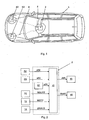
- eine Draufsicht auf ein Kraftfahrzeug,
- Fig. 2
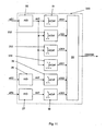
- ein Ausführungsbeispiel für ein Insassenschutzsystem,
- Fig. 3
- ein Ausführungsbeispiel eines Steueriangsmoduls,
- Fig. 4
- ein Ausführungsbeispiel eines Auslösemoduls,
- Fig. 5
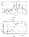
- ein Ausführungsbeispiel eines Ausgangssignals eines Crashsensors,
- Fig. 6
- das Integral des Ausgangssignals gemäß
Fig. 5 in einem Zeitintervall, - Fig. 7
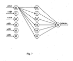
- ein Ausführungsbeispiel eines neuronalen Netzes,
- Fig. 8
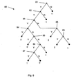
- ein Ausführungsbeispiel eines Entscheidungsbaumes,
- Fig. 9
- ein weiteres Ausführungsbeispiel eines Auslösemoduls,
- Fig. 10
- ein weiteres Ausführungsbeispiel eines Auslösemoduls und
- Fig. 11
- ein weiteres Ausführungsbeispiel eines Auslösemoduls.
- Fig. 1
- a top view of a motor vehicle,
- Fig. 2
- an exemplary embodiment of an occupant protection system,
- Fig. 3
- an embodiment of a Steueriangsmoduls,
- Fig. 4
- an embodiment of a trigger module,
- Fig. 5
- an embodiment of an output signal of a crash sensor,
- Fig. 6
- the integral of the output signal according to
Fig. 5 in a time interval, - Fig. 7
- an embodiment of a neural network,
- Fig. 8
- an embodiment of a decision tree,
- Fig. 9
- another embodiment of a triggering module,
- Fig. 10
- a further embodiment of a trigger module and
- Fig. 11
- Another embodiment of a trigger module.
Die Crashsensoren S2 und S3 sowie ein weiterer - wie in
Das Insassenschutzsystem umfasst zudem einen Gurtsensor 11 zum Erkennen, ob ein Sicherheitsgut angelegt ist, und zur Ausgabe einer entsprechenden Gurtinformation MGURT. Das Insassenschutzsystem umfasst weiterhin einen Sitzbelegungssensor 12 zum Erkennen, ob bzw. wie ein Sitz belegt ist, und zur Ausgabe einer entsprechenden Sitzbelegungsinformation MSITZ. Ein geeigneter Sitzbelegungssensor ist z.B. ein in den Sitz integrierter Drucksensor. Geeignet ist auch eine in dem unter der Internetseite www.informatik.uni-dortmund.de/airbag/seminarphase/hardware_vortrag.pdf veröffentlichten Artikel "Hardware und Mechanik realer Airbagsteuerungen", Kapitel 3.3 'Innenraum-Sensierung' offenbarte Infrarotabtastung. Mittels Infrarotabtastung und Fuzzy Logic lässt sich dabei nicht nur erkennen, ob ein Sitz belegt ist, sondern auch, ob es sich dabei um einen Gegenstand wie eine Tasche handelt oder um einen Menschen. Dazu sendet eine Zeile von z.B. acht oder mehr Leuchtdioden oberhalb des Sitzes Infrarotlicht aus und eine CCD-Matrix aus 64 Bildpunkten nimmt die so beleuchtete Szene auf. Diese charged coupled devices, kurz CCD, bestehen aus Photodioden und Verstärkerelementen in Matrixanordnungen. Einfallendes Licht setzt dabei jeweils Ladungsträger frei. Ein so erzeugtes Signal wird verstärkt und verarbeitet beziehungsweise gespeichert. Dieser Vorgang wird unter verschiedenen Winkeln wiederholt und so der Sitz abgetastet. Algorithmen der Bildverarbeitung und der Fuzzy Logic erkennen aus diesen Signalen Konturen von Objekten und Menschen.The occupant protection system also comprises a
Es kann weiterhin vorgesehen sein, dass das Insassenschutzsystem ein Bedienelement 14 zur Aktivierung bzw. Deaktivierung des Airbags 15 umfasst. Ein entsprechendes Schaltsignal ist mit Bezugszeichen EINAUS bezeichnet.It can further be provided that the occupant protection system comprises an operating
Das Steuergerät 2 umfasst ein Steuerungsmodul 10 zur Berechnung und Ausgabe eines Zündsignals AIR für den Airbag 15 und/oder eines Zündsignals GURT für den Gurtstraffer 16 in Abhängigkeit der Beschleunigungswerte aS1, aS2 bzw. aS3, der Gurtinformation MGURT, der Sitzbelegungsinformation MSITZ und des Schaltsignals EINAUS.The
Sowohl der Zündvorschlag CRASH als auch die Zündsignale AIR und GURT können Zündsignale im Sinne der Ansprüche sein. Sowohl der Zündvorschlag CRASH als auch die Zündsignale AIR und GURT können ein -z.B. dem in der
Die Abtastfrequenz der Δt der A/D-Wandler 25, 26 und 27 kann z.B. 4 kHz betragen. Das Auslösemodul 20 umfasst zudem (digitale) Integratoren 31, 32, 33, 34, 35 und 36.The sampling frequency of the Δt of the A /
Mittels des Integrators 31 wird ein Pseudogeschwindigkeitswert v0S1 zu einem Zeitpunkt t0 gemäß 
Mittels des Integrators 32 wird ein Pseudogeschwindigkeitswert v1S1 zu einem Zeitpunkt t0-τ1 gemäß 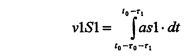
Mittels des Integrators 33 wird ein Pseudogeschwindigkeitswert v2S1 zu einem Zeitpunkt t0-τ2 gemäß 
Mittels des Integrators 34 wird ein Pseudogeschwindigkeitswert v3S1 zu einem Zeitpunkt t0-τ3 gemäß 
Mittels des Integrators 35 wird ein Pseudogeschwindigkeitswert v0S2 zum Zeitpunkt t0 gemäß 
Mittels des Integrators 36 wird ein Pseudogeschwindigkeitswert v0S3 zum Zeitpunkt t0 gemäß 
Die Wirkung der Integratoren 31, 32, 33, 34, 35 und 36 verdeutlichen
In der in
Die Pseudogeschwindigkeitswerte v0S1, v1S1, v2S1, v3S1, v0S2 und v0S3 sind Beispiele für zeitliche Mittelwerte im Sinne der Erfindung.The pseudo speed values v0S1, v1S1, v2S1, v3S1, v0S2 and v0S3 are examples of time averages in the sense of the invention.
Das Auslösemodul 20 umfasst weiterhin eine Auslöseerzeugung 30 zur Erzeugung des Zündvorschlags CRASH. Die Auslöseerzeugung 30 kann z.B. als neuronales Netz ausgebildet sein, wie es in
Das in
Eingangsgröße in den Eingangsknoten 50 ist der Pseudogeschwindigkeitswert v0S1, Eingangsgröße in den Eingangsknoten 51 ist der Pseudogeschwindigkeitswert v1S1, Eingangsgröße in den Eingangsknoten 52 ist der Pseudogeschwindigkeitswert v2S1, Eingangsgröße in den Eingangsknoten 53 ist der Pseudogeschwindigkeitswert v3S1, Eingangsgröße in den Eingangsknoten 54 ist der Pseudogeschwindigkeitswert v0S2, und Eingangsgröße in den Eingangsknoten 55 ist der Pseudogeschwindigkeitswert v0S3. Ausgangsgröße aus dem Ausgangskoten 70 ist der Zündvorschlag CRASH.Input to the
Einzelheiten zu neuronalen Netzen können der 
Die Auslöseerzeugung 30 gemäß
Ein mögliche (einfache) Implementierung des Integrators 31 (und entsprechend angepasst für die Integratoren 32, 33 und 34) ist z.B. 
![]()
![]()


Mittels des Integrators 233 wird ein Pseudogeschwindigkeitswert v2S1 zu einem Zeitpunkt t0 gemäß 
Mittels des Integrators 234 wird ein Pseudogeschwindigkeitswert v3S1 zu einem Zeitpunkt t0 gemäß 
Bei dem Auslösemodul 20 gemäß 
Die Erfindung führt insbesondere in Verbindung mit neuronalen Netzen, automatisch generierten Entscheidungsbäumen oder vergleichbaren lernenden Auswerteverfahren zu einer besonders robusten Ansteuerung von Airbags und Gurtstraffern.The invention leads in particular in conjunction with neural networks, automatically generated decision trees or comparable learning evaluation methods to a particularly robust control of airbags and belt tensioners.
Obwohl in den Aufführungsbeispielen an Hand von Airbags und Gurtstraffern für einen Frontalzusammenstoß erläutert, soll die Erfindung selbstverständlich nicht auf diesen Fall beschränkt sein. Die Erfindung ist auch für Seitenairbags und andere Insassenschutzsysteme anwendbar. In einer Implementierung für Seitenairbags können die Crashsensoren S2 und S3 z.B. in der B-Säule angeordnet werden. Es kann vorgesehen werden, dass auch für den Crashsensor S2 und/oder den Crashsensor S3 zumindest ein Pseudogeschwindigkeitswert über zumindest einem weiteren Zeitintervall gebildet wird.Although it is explained in the performance examples of airbags and belt tensioners for a head-on collision, it should be understood that the invention is not limited to this case. The invention is also applicable to side airbags and other occupant protection systems. In an implementation for side airbags, the crash sensors S2 and S3 may be e.g. be arranged in the B-pillar. It can be provided that at least one pseudo speed value is also formed for at least one further time interval for the crash sensor S2 and / or the crash sensor S3.
Ein Steuergerät im Sinne der Erfindung kann auch ein verteiltes System sein. Ein Steuergerät im Sinne der Erfindung muss nicht in einem einzigen Gehäuse untergebracht sein. Ein Steuergerät im Sinne der Erfindung kann auch ein einzelner Chip oder eine Platine sein.A control device according to the invention may also be a distributed system. A control device according to the invention need not be housed in a single housing. A control device according to the invention may also be a single chip or a circuit board.
Soweit Entscheidungsbäume im Zusammenhang mit der Erzeugung des Zündvorschlags CRASH genannt bzw. erwähnt sind, können diese auch durch Regression Trees, Association Tables, Rule Sets, Supervector Mashines oder andere Mashine-Learning-Verfahren ersetzt werden.As far as decision trees are mentioned or mentioned in connection with the generation of the ignition suggestion CRASH, these can also be replaced by regression trees, association tables, rule sets, supervector mashines or other mashine learning methods.
Anstelle der Bewegungsgrößen bzw. deren Mittelwerte können auch Differenzen von Bewegungsgrößen, Mittelwerte dieser Differenzen und/oder Differenzen von Mittelwerten verwendet werden. So kann z.B. vor den Integratoren 31, 32, 33, 34, 35, 36, 232, 233, 234 bzw. 334 in
Differenzen können auch zeitliche Differenzen sein. So kann vorgesehen sein, anstelle der abgetasteten Beschleunigungswerte as1, as2, as3 Differenzwerte Δas1, Δas2, Δas3 als Eingangsgrößen der Integratoren 31, 32, 33, 34, 35, 36, 232, 233, 234 bzw. 334 zu verwenden, wobei Δas1(t) gleich der Differenz as 1(t)-as1(t-τ), Δas2 gleich der Differenz as2(t)-as2(t-τ) oder der Differenz as2(t)-as3(t-τ) und Δas3 gleich der Differenz as3(t)-as3(t-τ) oder der Differenz as3(t)-as2(t-τ) ist.Differences can also be temporal differences. Thus, instead of the sampled acceleration values as1, as2, as3, it is possible to use difference values Δas1, Δas2, Δas3 as input variables of the
Entsprechend vorgenannten Ausführungen in Bezug auf eine Differenzbildung können Bewegungsgrößen im Sinne der Erfindung auch Differenzen von Bewegungsgrößen sein, wenn sie als Eingangsgrößen verwendet werden.According to the above statements with respect to a difference formation, motion quantities in the sense of the invention can also be differences of motion variables when they are used as input variables.
Analog kann mit den Pseudogeschwindigkeitswerten v0S1, v1S1, v2S1, v3S1, v0S2, v0S3 verfahren werden. Entsprechend können Mittelwerte von Bewegungsgrößen im Sinne der Erfindung auch Differenzen von Mittelwerten von Bewegungsgrößen bzw. Mittelwerte von Differenzen von Bewegungsgrößen sein, wenn sie als Eingangsgrößen verwendet werden.Analogously, the pseudo speed values v0S1, v1S1, v2S1, v3S1, v0S2, v0S3 can be used. Correspondingly, mean values of motion quantities in the sense of the invention can also be differences of mean values of motion quantities or mean values of differences of motion quantities if they are used as input variables.
- 11
- Kraftfahrzeugmotor vehicle
- 22
- Steuergerätcontrol unit
- 5, 65, 6
- Zuleitungenleads
- 1010
- Steuerungsmodulcontrol module
- 1111
- GurtsensorA web sensor
- 1212
- SitzbelegungssensorSeat occupancy sensor
- 1414
- Bedienelementoperating element
- 1515
- Airbagair bag
- 1616
- Gurtstrafferpretensioners
- 20, 120, 220, 32020, 120, 220, 320
- Auslösemodultriggering module
- 2121
- Feuertabellefire table
- 25, 26, 2725, 26, 27
- A/D WandlerA / D converter
- 3030
- Auslöseerzeugungtrigger generator
- 31, 32, 33, 34, 35, 36, 232, 233, 234, 33431, 32, 33, 34, 35, 36, 232, 233, 234, 334
- Integratorintegrator
- 4040
- Zeitintervalltime interval
- 50, 51, 52, 53, 54, 5550, 51, 52, 53, 54, 55
- Eingangsknoteninput node
- 60, 61, 62, 63, 64, 6560, 61, 62, 63, 64, 65
- verdeckter Knotenhidden knot
- 7070
- Ausgangsknotenoutput node
- 8080
- Entscheidungsbaumdecision tree
- 81, 82, 83, 84, 85, 86, 87, 88, 8981, 82, 83, 84, 85, 86, 87, 88, 89
- Abfragequery
- 132, 133, 134132, 133, 134
- TotzeitgliedDead time
- AIR, GURTAIR, BELT
- Zündsignalignition signal
- aS1, aS2, aS3, as1, as2, as3aS1, aS2, aS3, as1, as2, as3
- Beschleunigungswertacceleration value
- CRASHCRASH
- ZühdvorschlagZühdvorschlag
- EINAUSON OFF
- Schaltsignalswitching signal
- MGURTMGURT
- GurtinformationGurtinformation
- MSITZitem MSEAT
- SitzbelegungsinformationSeat occupancy information
- S1, S2, S3S1, S2, S3
- Crashsensorcrash sensor
- tt
- ZeitTime
- toto
- aktueller Zeitpunktcurrent time
- v0S1, v1S1, v2S1, v3S1, v0S2, v0S3v0S1, v1S1, v2S1, v3S1, v0S2, v0S3
- PseudogeschwindigkeitswertPseudo velocity value
- τ0, τ1, τ2, τ3 Längeτ 0 , τ 1 , τ 2 , τ 3 length
- eines Zeitintervallsa time interval
Claims (11)
- Occupant protection system for a motor vehicle (1), having at least one crash sensor (S1) for measuring a movement variable (aS1) of the motor vehicle (1), wherein the occupant protection system comprises an occupant protection device (15, 16) which can be controlled by means of a firing signal (CRASH, AIR, BELT), characterized in that the occupant protection system comprises a control unit (2) which is configured to determine the firing signal (CRASH, AIR, BELT) as a function of a chronological mean value (v0S1) of the signed movement variable (aS1), measured by means of the crash sensor (S1), over a first time interval ([t0-τ0,t0]) and of a chronological mean value (v1S1) of the specified movement variable (aS1), measured by means of the crash sensor (S1), over at least one second time interval ([t0-τ0-τ1,t0-τ1]) which is different from the first time interval ([t0-τ0,t0]) in terms of its length.
- Occupant protection system according to Claim 1, characterized in that the movement variable (aS1) is an acceleration.
- Occupant protection system according to Claim 1 or 2, characterized in that firing signal (CRASH, AIR, BELT) can be determined by means of the control unit (2) as a function of chronological mean values (v0S1, v1S1, v2S1, v3S1) of the movement variable (aS1) which is measured by means of the crash sensor (S1), in two to twenty different time intervals ([t0-τ0, t0), [t0-τ0-τ1,t0-τ1], [t0-τ0-t2, t0-τ2], [t0-τ0-τ3, t0-τ3]).
- Occupant protection system according to Claim 1, 2 or 3, characterized in that the firing signal (CRASH, AIR, BELT) can be determined by means of the control unit (2) as a function of chronological mean values (v0S1, v1s1, v2S1, v3S1) of the movement variable (aS1), measured by means of the crash sensor (S1), in two to five different time intervals ([t0-τ0,t0), [t0-τ0-τ1, t0-τ1], [t0-τ0-τ2; t0-τ2], [t0-τ0-τ3, t0-τ3]).
- Occupant protection system according to one of the preceding claims, characterized in that the time intervals ([t0-τ0,t0), [t0-τ0-τ1, t0-τ1], [t0-τ0-τ2, t0-τ2], [t0-τ0-τ3, t0-τ3]) are between 1 ms and 200 ms long.
- Occupant protection system according to one of the preceding claims, characterized in that the time intervals ([t0-τ0,t0), [t0-τ0-τ1,t0-τ1], [t0-τ0-τ2, t0-τ2], [t0-τ0-τ3, t0-τ3]) are essentially of equal length.
- Occupant protection system according to one of the preceding claims, characterized in that at least two time intervals ([t0-τ0,t0), [t0-τ0-τ1, t0-τ1], [t0-τ0-τ2, t0-τ2], [t0-τ0-τ3, t0-τ3]) are offset between 1 ms and 50 ms.
- Occupant protection system according to one of the preceding claims, characterized in that the time intervals ([t0-τ0,t0), [t0-τ0-τ1, t0-τ1], [t0-τ0-τ2, t0-τ2], [t0-τ0-τ3, t0-τ3]) are offset between 1 ms and 50 ms.
- Occupant protection system according to one of the preceding claims, wherein the occupant protection system comprises at least one further crash sensor (S2) for measuring a movement variable (aS2) of the motor vehicle (1), characterized in that the firing signal (CRASH, AIR, BELT) can additionally be determined by means of the control unit (2) as a function of at least one chronological mean value (v0S2) of the movement variable (aS2), measured by means of the further crash sensor (S2), over a time interval ([t0-τ0,t0]).
- Motor vehicle (1), characterized in that it has an occupant protection system according to one of the preceding claims.
- Method for operating an occupant protection system for a motor vehicle (1), wherein the occupant protection system comprises an occupant protection device which can be controlled by means of a firing signal (CRASH, AIR, BELT), characterized in that the firing signal (CRASH, AIR, BELT) is determined as a function of a chronological mean value (v0S1) of a measured, signed movement variable (aS1) over at least one first time interval ([t0-τ0,t0]) and of a chronological mean value (v1S1) of the specified movement variable (aS1), measured by means of the crash sensor (S1), over at least one second time interval ([t0-τ0-τ1,t0-τ1]) which is different from the first time interval ([t0-τ0,t0]) in terms of its length.
Applications Claiming Priority (5)
| Application Number | Priority Date | Filing Date | Title |
|---|---|---|---|
| DE10348999A DE10348999A1 (en) | 2003-10-17 | 2003-10-17 | Passenger protection system for a motor vehicle comprises a control unit determining an activation signal according to a temporal mean value of a movement variable measured by a crash sensor over a first time interval |
| DE10348997A DE10348997A1 (en) | 2003-10-17 | 2003-10-17 | Manufacture and operation of crash sensors and computing system for road vehicle involves setting up program with branching tree with question at each step producing binary 1 or 0 |
| DE10348998 | 2003-10-17 | ||
| DE102004004951 | 2004-01-31 | ||
| PCT/EP2004/011535 WO2005037611A1 (en) | 2003-10-17 | 2004-10-14 | Occupant protection system for a motor vehicle |
Publications (2)
| Publication Number | Publication Date |
|---|---|
| EP1680312A1 EP1680312A1 (en) | 2006-07-19 |
| EP1680312B1 true EP1680312B1 (en) | 2013-01-02 |
Family
ID=34437700
Family Applications (6)
| Application Number | Title | Priority Date | Filing Date |
|---|---|---|---|
| EP04765960A Active EP1678011B1 (en) | 2003-10-17 | 2004-10-14 | Method for generating a disconnection for triggering a passenger protection system of a motor vehicle |
| EP04790394A Active EP1680311B1 (en) | 2003-10-17 | 2004-10-14 | Motor vehicle equipped with an occupant protection system |
| EP04790395A Active EP1680312B1 (en) | 2003-10-17 | 2004-10-14 | Occupant protection system for a motor vehicle |
| EP04790397A Active EP1678014B1 (en) | 2003-10-17 | 2004-10-14 | Pedestrian protection system for a motor vehicle |
| EP04790393A Active EP1680310B1 (en) | 2003-10-17 | 2004-10-14 | Method for producing a motor vehicle |
| EP04765961A Not-in-force EP1678012B1 (en) | 2003-10-17 | 2004-10-14 | Method for the production of a motor vehicle |
Family Applications Before (2)
| Application Number | Title | Priority Date | Filing Date |
|---|---|---|---|
| EP04765960A Active EP1678011B1 (en) | 2003-10-17 | 2004-10-14 | Method for generating a disconnection for triggering a passenger protection system of a motor vehicle |
| EP04790394A Active EP1680311B1 (en) | 2003-10-17 | 2004-10-14 | Motor vehicle equipped with an occupant protection system |
Family Applications After (3)
| Application Number | Title | Priority Date | Filing Date |
|---|---|---|---|
| EP04790397A Active EP1678014B1 (en) | 2003-10-17 | 2004-10-14 | Pedestrian protection system for a motor vehicle |
| EP04790393A Active EP1680310B1 (en) | 2003-10-17 | 2004-10-14 | Method for producing a motor vehicle |
| EP04765961A Not-in-force EP1678012B1 (en) | 2003-10-17 | 2004-10-14 | Method for the production of a motor vehicle |
Country Status (7)
| Country | Link |
|---|---|
| US (2) | US7379804B2 (en) |
| EP (6) | EP1678011B1 (en) |
| JP (2) | JP2007508197A (en) |
| AT (4) | ATE381467T1 (en) |
| DE (3) | DE502004005768D1 (en) |
| ES (1) | ES2305865T3 (en) |
| WO (6) | WO2005037611A1 (en) |
Families Citing this family (16)
| Publication number | Priority date | Publication date | Assignee | Title |
|---|---|---|---|---|
| US7580782B2 (en) * | 1995-10-30 | 2009-08-25 | Automotive Technologies International, Inc. | Vehicular electronic system with crash sensors and occupant protection systems |
| DE102005038593A1 (en) * | 2005-08-16 | 2007-02-22 | Robert Bosch Gmbh | Contact sensor for a vehicle |
| DE102006042455A1 (en) * | 2006-02-21 | 2007-08-23 | Volkswagen Ag | Seat belt buckle for motor vehicle, has guide seat belt, which is loaded mechanically by seat belt buckle and in pushing condition of guide is detected by switch |
| DE102006044085B4 (en) * | 2006-09-20 | 2012-02-09 | Audi Ag | Collision and / or personal protection system for a motor vehicle |
| DE102007027649B4 (en) | 2007-06-15 | 2015-10-01 | Robert Bosch Gmbh | Method and control device for controlling personal protection devices and computer program and computer program product |
| DE102007050254B4 (en) | 2007-10-20 | 2022-02-17 | Andata Entwicklungstechnologie Gmbh & Co.Kg | Method of manufacturing a collision protection system for a motor vehicle |
| US8200595B1 (en) * | 2008-06-11 | 2012-06-12 | Fair Isaac Corporation | Determing a disposition of sensor-based events using decision trees with splits performed on decision keys |
| WO2010025206A2 (en) * | 2008-08-28 | 2010-03-04 | Trw Automotive U.S. Llc | Method and apparatus for controlling an actuatable safety device |
| DE102008045586B4 (en) | 2008-09-03 | 2017-09-14 | Audi Ag | Collision and / or personal protection system for a motor vehicle and method thereto |
| JP5257610B2 (en) * | 2009-03-10 | 2013-08-07 | 三菱自動車工業株式会社 | Vehicle collision detection structure |
| US8762009B2 (en) * | 2010-11-18 | 2014-06-24 | I.D. Systems, Inc. | Impact sensor calibration tool |
| DE102011102298B4 (en) | 2011-05-23 | 2014-03-06 | Audi Ag | Method for controlling restraint devices of a motor vehicle |
| WO2013176652A1 (en) * | 2012-05-22 | 2013-11-28 | Trw Automotive U.S. Llc | Hybrid method and apparatus for detecting a vehicle/pedestrian impact |
| DE102016205545A1 (en) * | 2016-04-04 | 2017-10-05 | Robert Bosch Gmbh | Method for determining an impact strength |
| TWI641522B (en) * | 2017-05-18 | 2018-11-21 | 晶翔微系統股份有限公司 | Deceleration alert device and method |
| WO2018227179A1 (en) | 2017-06-09 | 2018-12-13 | Isp Investments Llc | Small-molecule lactams in coamorphous pharmaceutical phases |
Family Cites Families (36)
| Publication number | Priority date | Publication date | Assignee | Title |
|---|---|---|---|---|
| JPH0471933A (en) * | 1990-07-10 | 1992-03-06 | Toyota Motor Corp | Travel control device for vehicle |
| US7635043B2 (en) * | 1991-07-09 | 2009-12-22 | Automotive Technologies International, Inc. | Crash sensor arrangement for controlling deployment of an occupant restraint device |
| US5684701A (en) * | 1995-06-07 | 1997-11-04 | Automotive Technologies International, Inc. | Method and apparatus for sensing a vehicle crash |
| US5498028A (en) | 1994-01-04 | 1996-03-12 | Trw Inc. | Method and apparatus for controlling an actuatable restraining device |
| JP3993253B2 (en) * | 1994-05-23 | 2007-10-17 | オートモーティブ・テクノロジーズ・インターナショナル,インク. | Side impact airbag system with predictive sensor |
| US5583771A (en) | 1994-08-04 | 1996-12-10 | Delco Electronics Corp. | Method and apparatus for distinguishing between deployment events and non-deployment events in an SIR system |
| GB2293681B (en) * | 1994-09-29 | 1998-08-12 | Autoliv Dev | Improvements in or relating to a safety arrangement |
| JPH09315261A (en) * | 1996-05-30 | 1997-12-09 | Toyota Motor Corp | Sum-of-product arithmetic circuit learning method and device thereof as well as starting controller of occupant protective device |
| US6070113A (en) * | 1996-06-21 | 2000-05-30 | Automotive Systems Laboratory, Inc. | Hybrid vehicle crash discrimination system |
| JPH1067294A (en) * | 1996-07-25 | 1998-03-10 | Automot Technol Internatl Inc | Method for detecting collision of vehicle and device thereof |
| DE19724101A1 (en) * | 1997-06-07 | 1998-12-10 | Bayerische Motoren Werke Ag | Process for controlling occupant safety devices as required |
| DE19729960A1 (en) * | 1997-07-12 | 1998-11-26 | Telefunken Microelectron | Method of detecting impacts |
| US6561301B1 (en) * | 1998-02-24 | 2003-05-13 | Kabushiki Kaisha Toyota Chuo Kenkyusho | Collision discriminating apparatus for vehicles |
| US6186539B1 (en) * | 1998-07-01 | 2001-02-13 | Trw Inc. | Method and apparatus for controlling an actuatable restraint device using crash severity indexing and crush zone sensor |
| US6219606B1 (en) * | 1998-11-16 | 2001-04-17 | Delphi Technologies, Inc. | Restraint deployment control method having a delayed adaptable deployment threshold |
| DE19854380A1 (en) * | 1998-11-25 | 2000-05-31 | Bayerische Motoren Werke Ag | Method for recognizing the severity of a vehicle collision |
| JP3436185B2 (en) * | 1999-02-09 | 2003-08-11 | トヨタ自動車株式会社 | Activation control device for occupant protection device |
| DE19917710A1 (en) * | 1999-04-20 | 2000-10-26 | Bosch Gmbh Robert | Procedure for formation of a triggering level for a vehicle restraining mechanism such as an airbag has a low pass filter through which the acceleration signal is passed so that the filtered signal can be compared with a threshold |
| DE19928517C2 (en) * | 1999-06-22 | 2001-09-06 | Pilz Gmbh & Co | Control system for controlling safety-critical processes |
| JP4153129B2 (en) * | 1999-07-14 | 2008-09-17 | オートリブ ディベロップメント エービー | Seat belt device |
| JP2001058552A (en) * | 1999-08-04 | 2001-03-06 | Takata Corp | Damage reduction system vehicle crash |
| DE10016142B4 (en) | 2000-03-31 | 2010-01-21 | Volkswagen Ag | Trigger switch for a personal protection system |
| DE10116142A1 (en) | 2000-04-05 | 2001-12-20 | Univ Ilmenau Tech | Method of speaker voice recognition by telephone signals, involves picking off the voice signal via a microphone forming part of the telephone |
| DE10035505A1 (en) * | 2000-07-21 | 2002-01-31 | Bayerische Motoren Werke Ag | Method for recognizing the severity of a vehicle collision |
| US6510914B2 (en) * | 2000-07-26 | 2003-01-28 | Honda Giken Kogyo Kabushiki Kaisha | Obstruction inference apparatus for vehicle |
| DE10040111A1 (en) | 2000-08-17 | 2002-02-28 | Bosch Gmbh Robert | Process for making a trigger decision for restraint devices |
| JP3788286B2 (en) * | 2001-01-19 | 2006-06-21 | トヨタ自動車株式会社 | Control device for occupant protection device |
| DE10103661C1 (en) * | 2001-01-27 | 2002-08-08 | Bosch Gmbh Robert | Side impact sensing method in a vehicle |
| DE10117220A1 (en) * | 2001-04-06 | 2002-10-10 | Conti Temic Microelectronic | Procedure for dissolving an occupant protection system in vehicles |
| US6529810B2 (en) * | 2001-04-09 | 2003-03-04 | Trw Inc. | Method and apparatus for controlling an actuatable restraining device using switched thresholds based on transverse acceleration |
| JP3608052B2 (en) * | 2001-08-09 | 2005-01-05 | トヨタ自動車株式会社 | Activation control device for occupant protection device |
| JP3819274B2 (en) | 2001-10-16 | 2006-09-06 | 三菱電機株式会社 | Collision form determination device and determination method |
| WO2003082639A1 (en) * | 2002-03-28 | 2003-10-09 | Autoliv Development Ab | An impact detector system |
| DE10227003A1 (en) * | 2002-06-18 | 2004-01-15 | Robert Bosch Gmbh | Method for controlling a restraint system |
| ITTO20021091A1 (en) | 2002-12-17 | 2004-06-18 | Trw Occupant Safety Systems S P A | METHOD OF CONTROL OF A VEHICLE HANDLING GROUP OF A VEHICLE FOR THE SAFETY OF THE PEDESTRIAN IN THE EVENT OF AN IMPACT AGAINST THE FRONT BUMPER OF THE VEHICLE ITSELF. |
| DE10305087B4 (en) * | 2003-02-07 | 2005-05-04 | Siemens Ag | Method and device for controlling an occupant protection device in a vehicle |
-
2004
- 2004-10-14 JP JP2006534682A patent/JP2007508197A/en active Pending
- 2004-10-14 WO PCT/EP2004/011535 patent/WO2005037611A1/en active Application Filing
- 2004-10-14 AT AT04765961T patent/ATE381467T1/en not_active IP Right Cessation
- 2004-10-14 DE DE502004005768T patent/DE502004005768D1/en active Active
- 2004-10-14 EP EP04765960A patent/EP1678011B1/en active Active
- 2004-10-14 JP JP2006534681A patent/JP4970945B2/en active Active
- 2004-10-14 EP EP04790394A patent/EP1680311B1/en active Active
- 2004-10-14 DE DE502004005769T patent/DE502004005769D1/en active Active
- 2004-10-14 DE DE502004006950T patent/DE502004006950D1/en active Active
- 2004-10-14 EP EP04790395A patent/EP1680312B1/en active Active
- 2004-10-14 WO PCT/EP2004/011533 patent/WO2005037610A1/en active IP Right Grant
- 2004-10-14 AT AT04765960T patent/ATE381466T1/en not_active IP Right Cessation
- 2004-10-14 EP EP04790397A patent/EP1678014B1/en active Active
- 2004-10-14 AT AT04790394T patent/ATE393065T1/en not_active IP Right Cessation
- 2004-10-14 US US10/576,062 patent/US7379804B2/en active Active
- 2004-10-14 WO PCT/EP2004/011532 patent/WO2005037609A1/en active Application Filing
- 2004-10-14 US US10/576,063 patent/US8096579B2/en active Active
- 2004-10-14 WO PCT/EP2004/011534 patent/WO2005035319A1/en active Application Filing
- 2004-10-14 EP EP04790393A patent/EP1680310B1/en active Active
- 2004-10-14 AT AT04790397T patent/ATE552148T1/en active
- 2004-10-14 ES ES04790394T patent/ES2305865T3/en active Active
- 2004-10-14 WO PCT/EP2004/011538 patent/WO2005035320A2/en active Application Filing
- 2004-10-14 EP EP04765961A patent/EP1678012B1/en not_active Not-in-force
- 2004-10-14 WO PCT/EP2004/011537 patent/WO2005037612A1/en active IP Right Grant
Also Published As
Similar Documents
| Publication | Publication Date | Title |
|---|---|---|
| EP1680312B1 (en) | Occupant protection system for a motor vehicle | |
| DE102007057727B4 (en) | Pedestrian collision detection device and pedestrian protection system | |
| DE19743009B4 (en) | Method and apparatus for single point sensing of front and side impact crash conditions | |
| EP0458796B1 (en) | Process for releasing restraining means | |
| DE102005059255B4 (en) | Method and apparatus for determining symmetric and asymmetric crash events with improved malfunction tolerances | |
| EP1409297B1 (en) | Method and device for controlling the triggering of a passive security system and the use thereof | |
| WO2001098117A1 (en) | Method and device for recognition of a collision with a pedestrian | |
| DE10065518A1 (en) | Method for triggering restraint devices in a motor vehicle | |
| EP1420983B1 (en) | Method for triggering at least one airbag in a vehicle | |
| DE10157203B4 (en) | Passive security system | |
| EP1133418B1 (en) | Method for judging the seriousness of a motor vehicle crash | |
| EP1634099A2 (en) | Device for the classification of at least one object by means of an environment sensor | |
| EP1334010B1 (en) | Restraining system comprising a restraining device for protecting at least one passenger and a method for controlling a restraining system | |
| EP1551670B1 (en) | Method for activating a restraint system in a vehicle | |
| DE10239406A1 (en) | Vehicle rollover detection device | |
| DE10035505A1 (en) | Method for recognizing the severity of a vehicle collision | |
| EP1551671B1 (en) | Device for controlling a retaining system | |
| EP1902908B1 (en) | Collision and/or passenger protection system for a motor vehicle | |
| DE102007004345B4 (en) | Method and control device for controlling personal protective equipment | |
| EP0852193A1 (en) | Method for triggering a safety device, particularly a belt tensioner in a passenger transport | |
| DE10348999A1 (en) | Passenger protection system for a motor vehicle comprises a control unit determining an activation signal according to a temporal mean value of a movement variable measured by a crash sensor over a first time interval | |
| DE19812830B4 (en) | Method and device for triggering an airbag with seat position detection | |
| DE10155751B4 (en) | A method of examining a vehicle acceleration relevant to triggering a passive safety device in a vehicle | |
| DE102006056836A1 (en) | Vehicle's person protection unit e.g. pedestrian protection unit, controlling method, involves evaluating temporal progression of signal, so that parameter is produced independent of value, which characterizes ejection of collision object | |
| DE102005015738B4 (en) | Method for generating a triggering signal for occupant protection systems |
Legal Events
| Date | Code | Title | Description |
|---|---|---|---|
| PUAI | Public reference made under article 153(3) epc to a published international application that has entered the european phase |
Free format text: ORIGINAL CODE: 0009012 |
|
| 17P | Request for examination filed |
Effective date: 20060517 |
|
| AK | Designated contracting states |
Kind code of ref document: A1 Designated state(s): AT BE BG CH CY CZ DE DK EE ES FI FR GB GR HU IE IT LI LU MC NL PL PT RO SE SI SK TR |
|
| 17Q | First examination report despatched |
Effective date: 20061115 |
|
| DAX | Request for extension of the european patent (deleted) | ||
| REG | Reference to a national code |
Ref country code: DE Ref legal event code: R079 Ref document number: 502004013979 Country of ref document: DE Free format text: PREVIOUS MAIN CLASS: B60R0021010000 Ipc: B60R0021013200 |
|
| RAP1 | Party data changed (applicant data changed or rights of an application transferred) |
Owner name: AUDI AG Owner name: ANDATA ENTWICKLUNGSTECHNOLOGIE GMBH & CO. KG Owner name: VOLKSWAGEN AKTIENGESELLSCHAFT |
|
| GRAP | Despatch of communication of intention to grant a patent |
Free format text: ORIGINAL CODE: EPIDOSNIGR1 |
|
| RIC1 | Information provided on ipc code assigned before grant |
Ipc: B60R 21/0132 20060101AFI20120627BHEP Ipc: B60R 21/0134 20060101ALI20120627BHEP |
|
| GRAS | Grant fee paid |
Free format text: ORIGINAL CODE: EPIDOSNIGR3 |
|
| GRAA | (expected) grant |
Free format text: ORIGINAL CODE: 0009210 |
|
| AK | Designated contracting states |
Kind code of ref document: B1 Designated state(s): AT BE BG CH CY CZ DE DK EE ES FI FR GB GR HU IE IT LI LU MC NL PL PT RO SE SI SK TR |
|
| REG | Reference to a national code |
Ref country code: GB Ref legal event code: FG4D Free format text: NOT ENGLISH |
|
| REG | Reference to a national code |
Ref country code: CH Ref legal event code: EP Ref country code: AT Ref legal event code: REF Ref document number: 591407 Country of ref document: AT Kind code of ref document: T Effective date: 20130115 |
|
| REG | Reference to a national code |
Ref country code: IE Ref legal event code: FG4D Free format text: LANGUAGE OF EP DOCUMENT: GERMAN |
|
| REG | Reference to a national code |
Ref country code: DE Ref legal event code: R096 Ref document number: 502004013979 Country of ref document: DE Effective date: 20130307 |
|
| REG | Reference to a national code |
Ref country code: NL Ref legal event code: VDEP Effective date: 20130102 |
|
| PG25 | Lapsed in a contracting state [announced via postgrant information from national office to epo] |
Ref country code: SI Free format text: LAPSE BECAUSE OF FAILURE TO SUBMIT A TRANSLATION OF THE DESCRIPTION OR TO PAY THE FEE WITHIN THE PRESCRIBED TIME-LIMIT Effective date: 20130102 |
|
| PG25 | Lapsed in a contracting state [announced via postgrant information from national office to epo] |
Ref country code: BG Free format text: LAPSE BECAUSE OF FAILURE TO SUBMIT A TRANSLATION OF THE DESCRIPTION OR TO PAY THE FEE WITHIN THE PRESCRIBED TIME-LIMIT Effective date: 20130402 Ref country code: ES Free format text: LAPSE BECAUSE OF FAILURE TO SUBMIT A TRANSLATION OF THE DESCRIPTION OR TO PAY THE FEE WITHIN THE PRESCRIBED TIME-LIMIT Effective date: 20130413 Ref country code: CY Free format text: LAPSE BECAUSE OF FAILURE TO SUBMIT A TRANSLATION OF THE DESCRIPTION OR TO PAY THE FEE WITHIN THE PRESCRIBED TIME-LIMIT Effective date: 20130102 Ref country code: SE Free format text: LAPSE BECAUSE OF FAILURE TO SUBMIT A TRANSLATION OF THE DESCRIPTION OR TO PAY THE FEE WITHIN THE PRESCRIBED TIME-LIMIT Effective date: 20130102 Ref country code: CZ Free format text: LAPSE BECAUSE OF FAILURE TO SUBMIT A TRANSLATION OF THE DESCRIPTION OR TO PAY THE FEE WITHIN THE PRESCRIBED TIME-LIMIT Effective date: 20130102 |
|
| PG25 | Lapsed in a contracting state [announced via postgrant information from national office to epo] |
Ref country code: PL Free format text: LAPSE BECAUSE OF FAILURE TO SUBMIT A TRANSLATION OF THE DESCRIPTION OR TO PAY THE FEE WITHIN THE PRESCRIBED TIME-LIMIT Effective date: 20130102 Ref country code: FI Free format text: LAPSE BECAUSE OF FAILURE TO SUBMIT A TRANSLATION OF THE DESCRIPTION OR TO PAY THE FEE WITHIN THE PRESCRIBED TIME-LIMIT Effective date: 20130102 Ref country code: PT Free format text: LAPSE BECAUSE OF FAILURE TO SUBMIT A TRANSLATION OF THE DESCRIPTION OR TO PAY THE FEE WITHIN THE PRESCRIBED TIME-LIMIT Effective date: 20130502 Ref country code: NL Free format text: LAPSE BECAUSE OF FAILURE TO SUBMIT A TRANSLATION OF THE DESCRIPTION OR TO PAY THE FEE WITHIN THE PRESCRIBED TIME-LIMIT Effective date: 20130102 Ref country code: GR Free format text: LAPSE BECAUSE OF FAILURE TO SUBMIT A TRANSLATION OF THE DESCRIPTION OR TO PAY THE FEE WITHIN THE PRESCRIBED TIME-LIMIT Effective date: 20130403 |
|
| PG25 | Lapsed in a contracting state [announced via postgrant information from national office to epo] |
Ref country code: DK Free format text: LAPSE BECAUSE OF FAILURE TO SUBMIT A TRANSLATION OF THE DESCRIPTION OR TO PAY THE FEE WITHIN THE PRESCRIBED TIME-LIMIT Effective date: 20130102 Ref country code: SK Free format text: LAPSE BECAUSE OF FAILURE TO SUBMIT A TRANSLATION OF THE DESCRIPTION OR TO PAY THE FEE WITHIN THE PRESCRIBED TIME-LIMIT Effective date: 20130102 Ref country code: EE Free format text: LAPSE BECAUSE OF FAILURE TO SUBMIT A TRANSLATION OF THE DESCRIPTION OR TO PAY THE FEE WITHIN THE PRESCRIBED TIME-LIMIT Effective date: 20130102 Ref country code: RO Free format text: LAPSE BECAUSE OF FAILURE TO SUBMIT A TRANSLATION OF THE DESCRIPTION OR TO PAY THE FEE WITHIN THE PRESCRIBED TIME-LIMIT Effective date: 20130102 |
|
| PLBE | No opposition filed within time limit |
Free format text: ORIGINAL CODE: 0009261 |
|
| STAA | Information on the status of an ep patent application or granted ep patent |
Free format text: STATUS: NO OPPOSITION FILED WITHIN TIME LIMIT |
|
| 26N | No opposition filed |
Effective date: 20131003 |
|
| REG | Reference to a national code |
Ref country code: DE Ref legal event code: R097 Ref document number: 502004013979 Country of ref document: DE Effective date: 20131003 |
|
| BERE | Be: lapsed |
Owner name: AUDI A.G. Effective date: 20131031 Owner name: ANDATA ENTWICKLUNGSTECHNOLOGIE GMBH & CO. KG Effective date: 20131031 Owner name: VOLKSWAGEN A.G. Effective date: 20131031 |
|
| PG25 | Lapsed in a contracting state [announced via postgrant information from national office to epo] |
Ref country code: MC Free format text: LAPSE BECAUSE OF FAILURE TO SUBMIT A TRANSLATION OF THE DESCRIPTION OR TO PAY THE FEE WITHIN THE PRESCRIBED TIME-LIMIT Effective date: 20130102 |
|
| REG | Reference to a national code |
Ref country code: CH Ref legal event code: PL |
|
| REG | Reference to a national code |
Ref country code: IE Ref legal event code: MM4A |
|
| PG25 | Lapsed in a contracting state [announced via postgrant information from national office to epo] |
Ref country code: CH Free format text: LAPSE BECAUSE OF NON-PAYMENT OF DUE FEES Effective date: 20131031 Ref country code: LI Free format text: LAPSE BECAUSE OF NON-PAYMENT OF DUE FEES Effective date: 20131031 |
|
| PG25 | Lapsed in a contracting state [announced via postgrant information from national office to epo] |
Ref country code: BE Free format text: LAPSE BECAUSE OF NON-PAYMENT OF DUE FEES Effective date: 20131031 |
|
| PG25 | Lapsed in a contracting state [announced via postgrant information from national office to epo] |
Ref country code: IE Free format text: LAPSE BECAUSE OF NON-PAYMENT OF DUE FEES Effective date: 20131014 |
|
| REG | Reference to a national code |
Ref country code: AT Ref legal event code: MM01 Ref document number: 591407 Country of ref document: AT Kind code of ref document: T Effective date: 20131014 |
|
| PG25 | Lapsed in a contracting state [announced via postgrant information from national office to epo] |
Ref country code: AT Free format text: LAPSE BECAUSE OF NON-PAYMENT OF DUE FEES Effective date: 20131014 |
|
| PG25 | Lapsed in a contracting state [announced via postgrant information from national office to epo] |
Ref country code: TR Free format text: LAPSE BECAUSE OF FAILURE TO SUBMIT A TRANSLATION OF THE DESCRIPTION OR TO PAY THE FEE WITHIN THE PRESCRIBED TIME-LIMIT Effective date: 20130102 |
|
| PG25 | Lapsed in a contracting state [announced via postgrant information from national office to epo] |
Ref country code: HU Free format text: LAPSE BECAUSE OF FAILURE TO SUBMIT A TRANSLATION OF THE DESCRIPTION OR TO PAY THE FEE WITHIN THE PRESCRIBED TIME-LIMIT; INVALID AB INITIO Effective date: 20041014 Ref country code: LU Free format text: LAPSE BECAUSE OF NON-PAYMENT OF DUE FEES Effective date: 20131014 |
|
| REG | Reference to a national code |
Ref country code: FR Ref legal event code: PLFP Year of fee payment: 12 |
|
| REG | Reference to a national code |
Ref country code: FR Ref legal event code: PLFP Year of fee payment: 13 |
|
| REG | Reference to a national code |
Ref country code: FR Ref legal event code: PLFP Year of fee payment: 14 |
|
| REG | Reference to a national code |
Ref country code: FR Ref legal event code: PLFP Year of fee payment: 15 |
|
| P01 | Opt-out of the competence of the unified patent court (upc) registered |
Effective date: 20230606 |
|
| PGFP | Annual fee paid to national office [announced via postgrant information from national office to epo] |
Ref country code: GB Payment date: 20231024 Year of fee payment: 20 |
|
| PGFP | Annual fee paid to national office [announced via postgrant information from national office to epo] |
Ref country code: IT Payment date: 20231024 Year of fee payment: 20 Ref country code: FR Payment date: 20231026 Year of fee payment: 20 Ref country code: DE Payment date: 20231031 Year of fee payment: 20 |