EP1676289B1 - Schutzschalter mit einer bimetallschnappscheibe - Google Patents
Schutzschalter mit einer bimetallschnappscheibe Download PDFInfo
- Publication number
- EP1676289B1 EP1676289B1 EP04790635A EP04790635A EP1676289B1 EP 1676289 B1 EP1676289 B1 EP 1676289B1 EP 04790635 A EP04790635 A EP 04790635A EP 04790635 A EP04790635 A EP 04790635A EP 1676289 B1 EP1676289 B1 EP 1676289B1
- Authority
- EP
- European Patent Office
- Prior art keywords
- connection
- housing
- bimetallic
- contact
- circuit breaker
- Prior art date
- Legal status (The legal status is an assumption and is not a legal conclusion. Google has not performed a legal analysis and makes no representation as to the accuracy of the status listed.)
- Expired - Lifetime
Links
- 239000000463 material Substances 0.000 claims description 8
- 229920003023 plastic Polymers 0.000 claims description 8
- 239000012780 transparent material Substances 0.000 claims description 3
- 230000001960 triggered effect Effects 0.000 description 4
- 238000005452 bending Methods 0.000 description 3
- 230000008878 coupling Effects 0.000 description 3
- 238000010168 coupling process Methods 0.000 description 3
- 238000005859 coupling reaction Methods 0.000 description 3
- 238000000926 separation method Methods 0.000 description 3
- 239000004020 conductor Substances 0.000 description 2
- 238000001514 detection method Methods 0.000 description 2
- 230000007935 neutral effect Effects 0.000 description 2
- 238000001816 cooling Methods 0.000 description 1
- 238000010586 diagram Methods 0.000 description 1
- 230000009977 dual effect Effects 0.000 description 1
- 238000004519 manufacturing process Methods 0.000 description 1
- 239000002184 metal Substances 0.000 description 1
- 238000000034 method Methods 0.000 description 1
- 230000003287 optical effect Effects 0.000 description 1
- 238000009417 prefabrication Methods 0.000 description 1
- 230000011664 signaling Effects 0.000 description 1
- 229910000679 solder Inorganic materials 0.000 description 1
- 239000007787 solid Substances 0.000 description 1
- 229920001187 thermosetting polymer Polymers 0.000 description 1
- 230000000007 visual effect Effects 0.000 description 1
Images


Classifications
-
- H—ELECTRICITY
- H01—ELECTRIC ELEMENTS
- H01H—ELECTRIC SWITCHES; RELAYS; SELECTORS; EMERGENCY PROTECTIVE DEVICES
- H01H71/00—Details of the protective switches or relays covered by groups H01H73/00 - H01H83/00
- H01H71/04—Means for indicating condition of the switching device
-
- H—ELECTRICITY
- H01—ELECTRIC ELEMENTS
- H01H—ELECTRIC SWITCHES; RELAYS; SELECTORS; EMERGENCY PROTECTIVE DEVICES
- H01H73/00—Protective overload circuit-breaking switches in which excess current opens the contacts by automatic release of mechanical energy stored by previous operation of a hand reset mechanism
- H01H73/22—Protective overload circuit-breaking switches in which excess current opens the contacts by automatic release of mechanical energy stored by previous operation of a hand reset mechanism having electrothermal release and no other automatic release
- H01H73/30—Protective overload circuit-breaking switches in which excess current opens the contacts by automatic release of mechanical energy stored by previous operation of a hand reset mechanism having electrothermal release and no other automatic release reset by push-button, pull-knob or slide
- H01H73/303—Protective overload circuit-breaking switches in which excess current opens the contacts by automatic release of mechanical energy stored by previous operation of a hand reset mechanism having electrothermal release and no other automatic release reset by push-button, pull-knob or slide with an insulating body insertable between the contacts when released by a bimetal element
-
- H—ELECTRICITY
- H01—ELECTRIC ELEMENTS
- H01H—ELECTRIC SWITCHES; RELAYS; SELECTORS; EMERGENCY PROTECTIVE DEVICES
- H01H71/00—Details of the protective switches or relays covered by groups H01H73/00 - H01H83/00
- H01H71/08—Terminals; Connections
- H01H2071/088—Terminals for switching devices which make the devices interchangeable, e.g. with fuses
Definitions
- the invention relates to a circuit breaker with a Bimetallschnappulation according to the preamble of claim 1.
- Bimetallschnappa which is fixed to a bimetallic connection. This is arranged within a housing base next to a fixed contact connection.
- the housing base can be covered by means of a plastic or metal existing cap.
- the Bimetallschnappa carries a bimetallic contact, which is inside the housing with a fixed contact of the fixed contact terminal in contacting overlap position.
- Such a circuit breaker is used in particular as a fuse element in circuits of a motor vehicle and plugged into corresponding flat fuse base of the motor vehicle.
- Other applications of such circuit breaker with Bimetallschnappulation are in electrical household appliances or the like. possible.
- the invention has for its object to provide an improved in terms of a trigger detection circuit breaker.
- an illuminated push button is provided, the housing internally with the Separating element is connected.
- a triggering of the circuit breaker is visually displayed in the form of an externally visible light signal.
- the coupling of the illuminated push button with a displaceable in the case of release between the contacts separating element from the outside of a faultless normal position to the travel of the separating element further from the switch housing outstanding push button position also be detected mechanically or manually.
- the push button also serves by its operation to return the separating element from the contact separation position, so that the contacts get into the contact position due to the spring force of the Bimetallschnappulation.
- the push button with the slider-like separating element is mechanically coupled.
- a snap or snap connection is provided.
- the push button at least one, preferably two locking arms with end locking cams, which engage in the production of the locking or snap connection in corresponding recesses of the separating element.
- the locking cams may be provided on the separating element and the recesses on the push button.
- an electric lighting element such as a lamp or light emitting diode
- the luminous element is arranged stationary in the housing or housing base.
- the luminous element can be connected inside the housing between the bimetallic connection and the fixed contact connection.
- the light-emitting element is flowed through when triggered Bimetallschnappulation so that in the OFF state, i. when the circuit breaker is tripped, the push button is illuminated.
- the luminous element is contacted with its one housing-internal connection with the bimetal terminal, while the second terminal of the luminous element is led out of the housing base.
- the outwardly guided light-emitting element connection is connected, for example, to a neutral conductor of a power network, this is Luminous element in the normal state, that is current flowing in contacting the overlapping position of the contacts and corresponding external wiring of the circuit breaker, so that the push button lights in the ON state and is unlit in a contact opening (OFF state).
- the luminous element is arranged within the housing or housing base in the region of a material recess of the push button. Through this material recess along the push button, a knob shaft and this superior knob portion is formed, which always at least partially surmounted even with a contact opening the light-emitting element.
- the shaft length is adapted to the travel of the coupled with the push button separating element, so that the push button with the knob shank can move without contact along the stationary light-emitting element or move. In this case, the distance formed between the button portion and the luminous element increases in the case of triggering about the travel of the separating element or the coupled with this push button.
- the push-button and the separating element moving in the release case between the contacts form a two-part separating slide in the latched coupling state, for the two parts of which expediently different materials are used.
- the separating element which rests in the installed state on the bimetallic contact and / or on the fixed contact, consists of a very temperature-resistant, i. heat-resistant plastic, suitably made of thermosetting plastic.
- the push button is made of a transparent material, preferably of a transparent plastic. This ensures that the light emitted by the luminous element passes to the outside via the button shaft and / or the knob section of the pushbutton projecting beyond it.
- the bimetal To achieve the highest possible degree of prefabrication with the smallest possible number of individual parts of the fixed contact terminal and the bimetal are formed as identical flat contacts. In the middle area of these are trough-like cranked. The trough formed thereby is then used either for fastening the Bimetallschnappulation or for receiving the fixed contact.
- the advantages achieved by the invention are in particular that a reliable tripping detection is achieved by a built-in a push button on this externally operable gate valve of a circuit breaker with Bimetallschnappulation lighting in a simple manner.
- the push button thus assumes a dual function, on the one hand in the actuation effected by the return of the separating element from the contact separation position and on the other hand in an optical signaling of an example overcurrent-induced tripping case of the circuit breaker.
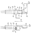
- the circuit breaker 1 according to the Fig. 1 to 3 comprises a housing cap 3 which can be covered with a housing cap 2, in which a bimetallic connection 4 and a fixed contact connection 5 are arranged parallel next to each other.
- the terminals 4 and 5 are designed as similar flat contacts and bent to form a trough 4b, 5b.
- the connections 4b, 5b are provided with openings 7.
- the openings 7 serve in the bimetallic connection 4 for fastening a Bimetallschnappulation 8 by means of a rivet 9 and the fixed contact terminal 5 for receiving a fixed contact 10.
- the Bimetallschnappulation 8 carries at its the bimetal 4 remote contact end 11 a bimetallic contact 12. This is in the installed state in contacting overlap position with the fixed contact 10 ( Fig. 2 ).
- a two-part separating slide 13 is disposed between the bimetal 4 and the fixed contact terminal 5.
- This consists of an L-shaped separating element 14 and a mechanically coupled with this push button 15.
- a designated detent or snap connection is formed by two provided in the exemplary embodiment of the push button 15 locking arms 16, the RONd cleanse each other facing cam 16 a wear.
- the push button 15 is snapped onto the separating element 14, wherein the locking cam 16a engage in corresponding recesses 17 of the separating element 14. This is comparatively clear Fig. 5 seen.
- Fig. 4 shows in a side view of the separating slide 13, the push button 15 to form a button shaft 15a and a button protruding thereon 15b a material recess 18 on.
- a light-emitting element 19 such as a light or a light emitting diode.
- the push button 15 is made of a transparent material, preferably made of transparent plastic.
- the light-emitting element 19 is in each case in the direction of the arrow 20 ( Fig. 4 ) extending position of the separating slide 13 from the button portion 15 b of the push button 15th at least partially covered in such a way that in each position of the separating slide 13, the light emitted by the light emitting element 19 via the knob shaft 15a and / or the button portion 15b of the push button 15 to the outside, ie outside of the switch housing 2, 3 passes.
- the isolating slide 13 has the function, in the case of, for example, triggered by an overcurrent circuit breaker 1, as a result, by moving open or bending the Bimetallschnappulation 8, the contact end 11 with the bimetallic contact 12 away from the fixed contact 10 to move between the two contacts 10, 11 ,
- the separating slide 13 is spring-loaded with a spring element 21.
- the spring element 21 is supported on the one hand on the side facing away from the push button 15 bottom 22 of the separating element 14 and on the other hand on the housing base 3 from.
- the electrically insulating separating function takes over the transverse to the extension of the push button 15 extending separating leg 14a of the separating element 14, which passes at right angles into the locking recesses 17 supporting shaft 14b of the separating element 14.
- the separating element 14 itself consists of a temperature or heat-resistant plastic material, preferably of a duroplastic. The reason for this is that the separating element 14 is always at least in approximate physical contact with the contacts 10, 12 which are in operation during operation.
- the push button 15 is moved due to its coupling with the separating element 14 by the same travel in the direction of travel 20 and thereby guided by this distance on the housing cap 2 to the outside of the switch housing 2, 3.
- the push button 15 projects beyond a dome-like button sleeve 23 placed on the housing cap 2. This can be a one-piece component of the housing cap 2 or can be snapped onto it as a separate part.
- the supply terminal 25 is expediently brought out on the same side of the housing housing housing 3, on which the terminal ends 4a, 5a of the terminals 4 and 5 are located.
- the further connection 19b of the light-emitting element 19 is guided into the hollow rivet 6 which fixes the bimetallic connection 4 within the housing base 3 and makes electrical contact with it via the bimetallic connection 4, z. B. plugged with the rivets 6 or soldered.
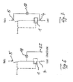
- Fig. 6 block diagram shown Verschaltungstage, in which the outwardly guided light-emitting element terminal 19a is connected, for example, to a neutral conductor of a power grid, the light-emitting element 19 is in the normal state, ie current flowing in contact with the overlapping position of the contacts.
- the Push button With appropriate external wiring lights up the Push button in the ON state and is unlit in the OFF state with open contacts 10,12.
- the light-emitting element 19 can also be wired exclusively inside the housing in a manner not shown.
- the switching on of the light-emitting element 19 can in turn be connected with a series connection of the ohmic resistor 24 and the light-emitting element 19 between the bimetallic connection 4 and the fixed contact connection 5.
- the light-emitting element 19 is current-flowed when the bimetallic snap-action disk 8 is triggered, so that in the OFF state the pushbutton 15 is illuminated and unlit in the ON state.
- the described circuit breaker 1 with illuminated push button 15 is suitable for a variety of applications, such as motor, transformer or cable drum protection.
Landscapes
- Thermally Actuated Switches (AREA)
- Push-Button Switches (AREA)
- Adornments (AREA)
- Toys (AREA)
- Switches With Compound Operations (AREA)
Priority Applications (1)
| Application Number | Priority Date | Filing Date | Title |
|---|---|---|---|
| PL04790635T PL1676289T3 (pl) | 2003-10-21 | 2004-10-19 | Wyłącznik ochronny z bimetaliczną tarczą zatrzaskową |
Applications Claiming Priority (2)
| Application Number | Priority Date | Filing Date | Title |
|---|---|---|---|
| DE10348864A DE10348864A1 (de) | 2003-10-21 | 2003-10-21 | Schutzschalter mit einer Bimetallschnappscheibe |
| PCT/EP2004/011813 WO2005041239A1 (de) | 2003-10-21 | 2004-10-19 | Schutzschalter mit einer bimetallschnappscheibe |
Publications (2)
| Publication Number | Publication Date |
|---|---|
| EP1676289A1 EP1676289A1 (de) | 2006-07-05 |
| EP1676289B1 true EP1676289B1 (de) | 2008-07-09 |
Family
ID=34484859
Family Applications (1)
| Application Number | Title | Priority Date | Filing Date |
|---|---|---|---|
| EP04790635A Expired - Lifetime EP1676289B1 (de) | 2003-10-21 | 2004-10-19 | Schutzschalter mit einer bimetallschnappscheibe |
Country Status (8)
| Country | Link |
|---|---|
| US (1) | US7336149B2 (pl) |
| EP (1) | EP1676289B1 (pl) |
| CN (1) | CN100490046C (pl) |
| AT (1) | ATE400889T1 (pl) |
| CA (1) | CA2539836C (pl) |
| DE (3) | DE20321765U1 (pl) |
| PL (1) | PL1676289T3 (pl) |
| WO (1) | WO2005041239A1 (pl) |
Families Citing this family (11)
| Publication number | Priority date | Publication date | Assignee | Title |
|---|---|---|---|---|
| DE102008049507A1 (de) * | 2008-09-29 | 2010-04-01 | Ellenberger & Poensgen Gmbh | Miniatur-Schutzschalter |
| CN101777464B (zh) * | 2009-01-12 | 2012-09-26 | 游聪谋 | 显示异常状态的断电装置 |
| CN101777463B (zh) * | 2009-01-12 | 2012-05-30 | 游聪谋 | 断电器 |
| US7948351B2 (en) * | 2009-04-09 | 2011-05-24 | Tsung Mou Yu | Circuit protection device having warning function |
| US7683750B1 (en) * | 2009-04-14 | 2010-03-23 | Tsung Mou Yu | Warning device for circuit breaker |
| DE102011015449B4 (de) * | 2011-01-25 | 2014-09-25 | Ellenberger & Poensgen Gmbh | Schalteinheit zum Schalten von hohen Gleichspannungen |
| DE102012024608B4 (de) | 2012-12-15 | 2015-04-16 | Ellenberger & Poensgen Gmbh | Schutzschalter und Adapter für einen Schutzschalter |
| CN111731478B (zh) * | 2019-07-15 | 2022-01-07 | 北京京东乾石科技有限公司 | 通断控制器、通断控制方法、装置、设备、无人机系统 |
| US10796872B1 (en) * | 2019-09-01 | 2020-10-06 | Kuoyuh W.L. Enterprise Co., Ltd. | Vehicle circuit breaker |
| CN217158857U (zh) * | 2022-05-06 | 2022-08-09 | 苏州益而益电器制造有限公司 | 电源插头以及控制电路装置 |
| US11990303B1 (en) * | 2022-12-06 | 2024-05-21 | David Worsham | Testable thermal circuit breaker |
Family Cites Families (14)
| Publication number | Priority date | Publication date | Assignee | Title |
|---|---|---|---|---|
| US3311725A (en) * | 1965-10-23 | 1967-03-28 | Mechanical Products Inc | Circuit breaker with lost motion lockout member for interposing between contacts |
| GB1281695A (en) * | 1968-11-22 | 1972-07-12 | Arrow Hart Europe Ltd | Improvements in electric switches |
| US4342979A (en) * | 1980-07-14 | 1982-08-03 | Jet Accessories, Inc. | Lighted circuit breaker |
| DE3342144A1 (de) * | 1983-11-22 | 1985-05-30 | Ellenberger & Poensgen Gmbh, 8503 Altdorf | Druckknopfbetaetigter ueberstromschutzschalter |
| US4633240A (en) * | 1984-12-05 | 1986-12-30 | Guim Industries, Inc. | Lightened circuit breaker |
| US4630020A (en) * | 1985-03-19 | 1986-12-16 | Yang Tai Her | Protective circuit breaker (I) |
| DE8521611U1 (de) * | 1985-07-26 | 1988-10-20 | Ellenberger & Poensgen Gmbh, 8503 Altdorf | Druckknopfbetätigter Überstromschutzschalter |
| WO1987003420A1 (en) * | 1985-11-27 | 1987-06-04 | Slater Electric, Inc. | Unitary switch and circuit breaker |
| DE9313277U1 (de) | 1993-09-03 | 1993-10-14 | Blaupunkt-Werke Gmbh, 31139 Hildesheim | Tastenanordnung für einen Tippschalter |
| US5513063A (en) * | 1993-12-06 | 1996-04-30 | Wu; Well S. | Combined electrical plug and circuit breaker |
| US5742219A (en) * | 1994-04-28 | 1998-04-21 | Siemens Electromechanical Components, Inc. | Switchable circuit breaker |
| DE29824696U1 (de) | 1998-12-09 | 2002-06-13 | Ellenberger & Poensgen GmbH, 90518 Altdorf | Schutzschalter zur Absicherung von Stromkreisen |
| US6542061B2 (en) * | 2001-04-16 | 2003-04-01 | Cathy D. Santa Cruz | Indicator light for use in combination with an electrical circuit protector or fuse |
| US6563414B2 (en) * | 2001-04-19 | 2003-05-13 | Tsung-Mou Yu | Switch having a bimetal plate with two legs |
-
2003
- 2003-10-21 DE DE20321765U patent/DE20321765U1/de not_active Expired - Lifetime
- 2003-10-21 DE DE10348864A patent/DE10348864A1/de not_active Ceased
-
2004
- 2004-10-19 EP EP04790635A patent/EP1676289B1/de not_active Expired - Lifetime
- 2004-10-19 DE DE502004007576T patent/DE502004007576D1/de not_active Expired - Lifetime
- 2004-10-19 AT AT04790635T patent/ATE400889T1/de active
- 2004-10-19 WO PCT/EP2004/011813 patent/WO2005041239A1/de not_active Ceased
- 2004-10-19 PL PL04790635T patent/PL1676289T3/pl unknown
- 2004-10-19 CN CNB2004800280539A patent/CN100490046C/zh not_active Expired - Fee Related
- 2004-10-19 CA CA002539836A patent/CA2539836C/en not_active Expired - Fee Related
-
2006
- 2006-04-21 US US11/408,365 patent/US7336149B2/en not_active Expired - Fee Related
Also Published As
| Publication number | Publication date |
|---|---|
| DE20321765U1 (de) | 2009-09-17 |
| CN1860574A (zh) | 2006-11-08 |
| DE502004007576D1 (de) | 2008-08-21 |
| PL1676289T3 (pl) | 2009-01-30 |
| WO2005041239A1 (de) | 2005-05-06 |
| CA2539836A1 (en) | 2005-05-06 |
| CA2539836C (en) | 2010-02-02 |
| CN100490046C (zh) | 2009-05-20 |
| EP1676289A1 (de) | 2006-07-05 |
| DE10348864A1 (de) | 2005-06-02 |
| ATE400889T1 (de) | 2008-07-15 |
| US7336149B2 (en) | 2008-02-26 |
| US20060186984A1 (en) | 2006-08-24 |
Similar Documents
| Publication | Publication Date | Title |
|---|---|---|
| EP1676289B1 (de) | Schutzschalter mit einer bimetallschnappscheibe | |
| US7264392B2 (en) | Light string system | |
| US4037068A (en) | Two-stage rocker switch for controlling a fluorescent lamp circuit | |
| EP0377116B1 (de) | Tastschalter | |
| US8052442B1 (en) | Light string system | |
| DE102007023944B4 (de) | Druckschalter | |
| DE3227091C2 (pl) | ||
| EP0151692B1 (de) | Druckknopfbetätigter Überstromschutzschalter | |
| DE3932604C1 (pl) | ||
| DE4242100B4 (de) | Elektrisches Schaltgerät | |
| EP0222181B1 (de) | Überstromschutzschalter | |
| DE102009042615B4 (de) | Anschlusselement zur elektrischen Anbindung einer LED | |
| EP0211282A1 (de) | Überstromschutzschalter | |
| EP0587056B1 (de) | Wipptaster | |
| DE19637706A1 (de) | Thermoschalter mit Rückstellung | |
| DE2734258C3 (de) | Innenleuchte für Kraftfahrzeuge | |
| DE3817797C2 (pl) | ||
| CH641291A5 (de) | Elektrischer installationstaster. | |
| EP0399419A3 (de) | Elektrischer Schnappschalter, insbesondere Mikroschalter | |
| EP1353346B1 (de) | Gehäuse aus Gehäuse-Oberteil und Gehäuse-Unterteil mit mittels Tastenknöpfen betätigbaren Tastschaltern | |
| DE4414859C1 (de) | Thermoschalter | |
| WO1994019817A1 (de) | Elektrischer schalter mit leuchtanzeige | |
| DE19927187A1 (de) | Ablagefach mit Beleuchtungseinrichtung | |
| DE19803560A1 (de) | Elektrischer Schalter | |
| DE10028707A1 (de) | Zugtaster |
Legal Events
| Date | Code | Title | Description |
|---|---|---|---|
| PUAI | Public reference made under article 153(3) epc to a published international application that has entered the european phase |
Free format text: ORIGINAL CODE: 0009012 |
|
| 17P | Request for examination filed |
Effective date: 20060202 |
|
| AK | Designated contracting states |
Kind code of ref document: A1 Designated state(s): AT BE BG CH CY CZ DE DK EE ES FI FR GB GR HU IE IT LI LU MC NL PL PT RO SE SI SK TR |
|
| 17Q | First examination report despatched |
Effective date: 20060829 |
|
| DAX | Request for extension of the european patent (deleted) | ||
| GRAP | Despatch of communication of intention to grant a patent |
Free format text: ORIGINAL CODE: EPIDOSNIGR1 |
|
| GRAS | Grant fee paid |
Free format text: ORIGINAL CODE: EPIDOSNIGR3 |
|
| GRAA | (expected) grant |
Free format text: ORIGINAL CODE: 0009210 |
|
| AK | Designated contracting states |
Kind code of ref document: B1 Designated state(s): AT BE BG CH CY CZ DE DK EE ES FI FR GB GR HU IE IT LI LU MC NL PL PT RO SE SI SK TR |
|
| REG | Reference to a national code |
Ref country code: GB Ref legal event code: FG4D Free format text: NOT ENGLISH |
|
| REG | Reference to a national code |
Ref country code: CH Ref legal event code: EP Ref country code: CH Ref legal event code: NV |
|
| REF | Corresponds to: |
Ref document number: 502004007576 Country of ref document: DE Date of ref document: 20080821 Kind code of ref document: P |
|
| REG | Reference to a national code |
Ref country code: IE Ref legal event code: FG4D Free format text: LANGUAGE OF EP DOCUMENT: GERMAN |
|
| NLV1 | Nl: lapsed or annulled due to failure to fulfill the requirements of art. 29p and 29m of the patents act | ||
| REG | Reference to a national code |
Ref country code: HU Ref legal event code: AG4A Ref document number: E004069 Country of ref document: HU |
|
| PG25 | Lapsed in a contracting state [announced via postgrant information from national office to epo] |
Ref country code: NL Free format text: LAPSE BECAUSE OF FAILURE TO SUBMIT A TRANSLATION OF THE DESCRIPTION OR TO PAY THE FEE WITHIN THE PRESCRIBED TIME-LIMIT Effective date: 20080709 Ref country code: ES Free format text: LAPSE BECAUSE OF FAILURE TO SUBMIT A TRANSLATION OF THE DESCRIPTION OR TO PAY THE FEE WITHIN THE PRESCRIBED TIME-LIMIT Effective date: 20081020 Ref country code: PT Free format text: LAPSE BECAUSE OF FAILURE TO SUBMIT A TRANSLATION OF THE DESCRIPTION OR TO PAY THE FEE WITHIN THE PRESCRIBED TIME-LIMIT Effective date: 20081209 |
|
| REG | Reference to a national code |
Ref country code: PL Ref legal event code: T3 |
|
| PG25 | Lapsed in a contracting state [announced via postgrant information from national office to epo] |
Ref country code: BG Free format text: LAPSE BECAUSE OF FAILURE TO SUBMIT A TRANSLATION OF THE DESCRIPTION OR TO PAY THE FEE WITHIN THE PRESCRIBED TIME-LIMIT Effective date: 20081009 Ref country code: FI Free format text: LAPSE BECAUSE OF FAILURE TO SUBMIT A TRANSLATION OF THE DESCRIPTION OR TO PAY THE FEE WITHIN THE PRESCRIBED TIME-LIMIT Effective date: 20080709 Ref country code: SI Free format text: LAPSE BECAUSE OF FAILURE TO SUBMIT A TRANSLATION OF THE DESCRIPTION OR TO PAY THE FEE WITHIN THE PRESCRIBED TIME-LIMIT Effective date: 20080709 |
|
| REG | Reference to a national code |
Ref country code: IE Ref legal event code: FD4D |
|
| BERE | Be: lapsed |
Owner name: ELLENBERGER & POENSGEN G.M.B.H. Effective date: 20081031 |
|
| PG25 | Lapsed in a contracting state [announced via postgrant information from national office to epo] |
Ref country code: EE Free format text: LAPSE BECAUSE OF FAILURE TO SUBMIT A TRANSLATION OF THE DESCRIPTION OR TO PAY THE FEE WITHIN THE PRESCRIBED TIME-LIMIT Effective date: 20080709 Ref country code: DK Free format text: LAPSE BECAUSE OF FAILURE TO SUBMIT A TRANSLATION OF THE DESCRIPTION OR TO PAY THE FEE WITHIN THE PRESCRIBED TIME-LIMIT Effective date: 20080709 Ref country code: IE Free format text: LAPSE BECAUSE OF FAILURE TO SUBMIT A TRANSLATION OF THE DESCRIPTION OR TO PAY THE FEE WITHIN THE PRESCRIBED TIME-LIMIT Effective date: 20080709 |
|
| PLBE | No opposition filed within time limit |
Free format text: ORIGINAL CODE: 0009261 |
|
| STAA | Information on the status of an ep patent application or granted ep patent |
Free format text: STATUS: NO OPPOSITION FILED WITHIN TIME LIMIT |
|
| PG25 | Lapsed in a contracting state [announced via postgrant information from national office to epo] |
Ref country code: SK Free format text: LAPSE BECAUSE OF FAILURE TO SUBMIT A TRANSLATION OF THE DESCRIPTION OR TO PAY THE FEE WITHIN THE PRESCRIBED TIME-LIMIT Effective date: 20080709 Ref country code: MC Free format text: LAPSE BECAUSE OF NON-PAYMENT OF DUE FEES Effective date: 20081031 Ref country code: RO Free format text: LAPSE BECAUSE OF FAILURE TO SUBMIT A TRANSLATION OF THE DESCRIPTION OR TO PAY THE FEE WITHIN THE PRESCRIBED TIME-LIMIT Effective date: 20080709 |
|
| 26N | No opposition filed |
Effective date: 20090414 |
|
| PG25 | Lapsed in a contracting state [announced via postgrant information from national office to epo] |
Ref country code: IT Free format text: LAPSE BECAUSE OF FAILURE TO SUBMIT A TRANSLATION OF THE DESCRIPTION OR TO PAY THE FEE WITHIN THE PRESCRIBED TIME-LIMIT Effective date: 20080709 |
|
| PG25 | Lapsed in a contracting state [announced via postgrant information from national office to epo] |
Ref country code: BE Free format text: LAPSE BECAUSE OF NON-PAYMENT OF DUE FEES Effective date: 20081031 |
|
| PG25 | Lapsed in a contracting state [announced via postgrant information from national office to epo] |
Ref country code: SE Free format text: LAPSE BECAUSE OF FAILURE TO SUBMIT A TRANSLATION OF THE DESCRIPTION OR TO PAY THE FEE WITHIN THE PRESCRIBED TIME-LIMIT Effective date: 20081009 |
|
| PG25 | Lapsed in a contracting state [announced via postgrant information from national office to epo] |
Ref country code: LU Free format text: LAPSE BECAUSE OF NON-PAYMENT OF DUE FEES Effective date: 20081019 Ref country code: CY Free format text: LAPSE BECAUSE OF FAILURE TO SUBMIT A TRANSLATION OF THE DESCRIPTION OR TO PAY THE FEE WITHIN THE PRESCRIBED TIME-LIMIT Effective date: 20080709 |
|
| PG25 | Lapsed in a contracting state [announced via postgrant information from national office to epo] |
Ref country code: TR Free format text: LAPSE BECAUSE OF FAILURE TO SUBMIT A TRANSLATION OF THE DESCRIPTION OR TO PAY THE FEE WITHIN THE PRESCRIBED TIME-LIMIT Effective date: 20080709 |
|
| PG25 | Lapsed in a contracting state [announced via postgrant information from national office to epo] |
Ref country code: GR Free format text: LAPSE BECAUSE OF FAILURE TO SUBMIT A TRANSLATION OF THE DESCRIPTION OR TO PAY THE FEE WITHIN THE PRESCRIBED TIME-LIMIT Effective date: 20081010 |
|
| PGFP | Annual fee paid to national office [announced via postgrant information from national office to epo] |
Ref country code: FR Payment date: 20131018 Year of fee payment: 10 Ref country code: AT Payment date: 20131021 Year of fee payment: 10 Ref country code: DE Payment date: 20131028 Year of fee payment: 10 Ref country code: GB Payment date: 20131022 Year of fee payment: 10 Ref country code: CH Payment date: 20131023 Year of fee payment: 10 Ref country code: CZ Payment date: 20131010 Year of fee payment: 10 |
|
| PGFP | Annual fee paid to national office [announced via postgrant information from national office to epo] |
Ref country code: PL Payment date: 20131008 Year of fee payment: 10 Ref country code: HU Payment date: 20131014 Year of fee payment: 10 |
|
| REG | Reference to a national code |
Ref country code: DE Ref legal event code: R119 Ref document number: 502004007576 Country of ref document: DE |
|
| REG | Reference to a national code |
Ref country code: CH Ref legal event code: PL |
|
| REG | Reference to a national code |
Ref country code: AT Ref legal event code: MM01 Ref document number: 400889 Country of ref document: AT Kind code of ref document: T Effective date: 20141019 |
|
| GBPC | Gb: european patent ceased through non-payment of renewal fee |
Effective date: 20141019 |
|
| PG25 | Lapsed in a contracting state [announced via postgrant information from national office to epo] |
Ref country code: LI Free format text: LAPSE BECAUSE OF NON-PAYMENT OF DUE FEES Effective date: 20141031 Ref country code: CZ Free format text: LAPSE BECAUSE OF NON-PAYMENT OF DUE FEES Effective date: 20141019 Ref country code: CH Free format text: LAPSE BECAUSE OF NON-PAYMENT OF DUE FEES Effective date: 20141031 Ref country code: DE Free format text: LAPSE BECAUSE OF NON-PAYMENT OF DUE FEES Effective date: 20150501 Ref country code: GB Free format text: LAPSE BECAUSE OF NON-PAYMENT OF DUE FEES Effective date: 20141019 |
|
| REG | Reference to a national code |
Ref country code: FR Ref legal event code: ST Effective date: 20150630 |
|
| PG25 | Lapsed in a contracting state [announced via postgrant information from national office to epo] |
Ref country code: HU Free format text: LAPSE BECAUSE OF NON-PAYMENT OF DUE FEES Effective date: 20141020 Ref country code: AT Free format text: LAPSE BECAUSE OF NON-PAYMENT OF DUE FEES Effective date: 20141019 Ref country code: FR Free format text: LAPSE BECAUSE OF NON-PAYMENT OF DUE FEES Effective date: 20141031 |
|
| PG25 | Lapsed in a contracting state [announced via postgrant information from national office to epo] |
Ref country code: PL Free format text: LAPSE BECAUSE OF NON-PAYMENT OF DUE FEES Effective date: 20141019 |